تعادلبخشی فن
(اطلاعات استفادهشده از GOST 31350-2007 “VIBRATION. INDUSTRIAL FANS. REQUIREMENTS FOR PRODUCED VIBRATION AND BALANCING QUALITY” — یک استاندارد بیندولتی که از ISO 14694:2003 “Industrial fans — Specifications for balance quality and vibration levels” توسعه یافته است)
یادداشت منبع: این صفحه بر اساس الزامات ارتعاش فن و کیفیت بالانس معادل با ISO 14694:2003 و اقتباسهای بیندولتی مرتبط (GOST) از استانداردهای ISO تهیه شده است که نامگذاری آنها با شمارههای انتشار اصلی ISO متفاوت است. هر جا اصطلاحات قدیمی ISO 1940-1 دیده میشود، استاندارد جاری کیفیت بالانس ISO 21940-11 است (قبلاً ISO 1940-1).
لرزش لرزش تولید شده توسط فن یکی از مهمترین مشخصات فنی آن است. نشان دهنده کیفیت طراحی و ساخت محصول است. افزایش لرزش ممکن است نشان دهنده نصب نامناسب فن، خراب شدن وضعیت فنی آن و غیره باشد. به همین دلیل، لرزش فن معمولاً در هنگام آزمایش های پذیرش، هنگام نصب قبل از راه اندازی و همچنین هنگام اجرای برنامه نظارت بر وضعیت دستگاه اندازه گیری می شود. از داده های ارتعاش فن نیز در طراحی سیستم های پشتیبانی و متصل (کانال) آن استفاده می شود. اندازهگیری ارتعاش معمولاً با درگاههای مکش و تخلیه باز انجام میشود، اما باید توجه داشت که ارتعاش فن میتواند با تغییر در آیرودینامیک جریان هوا، سرعت چرخش و سایر ویژگیها به طور قابل توجهی متفاوت باشد.
GOST ISO 10816-1-97 (ISO 10816-1:1995)، GOST ISO 10816-3-2002 (ISO 10816-3:1998)، و GOST 31351-2007 (ISO 14695:2003) روشهای اندازهگیری را تعیین میکنند و محلهای نصب حسگر ارتعاش را تعریف مینمایند. اگر اندازهگیریهای ارتعاش برای ارزیابی اثر آنها بر کانال یا پایه فن انجام شوند، نقاط اندازهگیری متناسب با آن انتخاب میشوند.
اندازه گیری ارتعاش فن می تواند گران باشد و گاهی اوقات هزینه آنها به طور قابل توجهی از هزینه تولید خود محصول بیشتر می شود. بنابراین، هر گونه محدودیت در مقادیر تک تک اجزای ارتعاش گسسته یا پارامترهای ارتعاش در باندهای فرکانسی تنها زمانی باید اعمال شود که بیش از این مقادیر نشان دهنده نقص فن باشد. تعداد نقاط اندازه گیری ارتعاش نیز باید بر اساس استفاده مورد نظر از نتایج اندازه گیری محدود شود. معمولاً برای ارزیابی وضعیت ارتعاش فن اندازه گیری ارتعاش در پایه های فن کافی است.
پایه همان چیزی است که فن روی آن نصب شده و پشتیبانی لازم را برای فن فراهم می کند. جرم و سفتی پایه برای جلوگیری از تقویت ارتعاش منتقل شده از طریق آن انتخاب می شود.
پشتیبانی ها دو نوع هستند:
- تکیهگاه انعطافپذیر: سامانه تکیهگاه فن که بهگونهای طراحی شده است که نخستین فرکانس طبیعی تکیهگاه بهطور قابلملاحظهای کمتر از فرکانس چرخشی کاری فن باشد. هنگام تعیین میزان انعطافپذیری تکیهگاه، باید درجهای الاستیک بین فن و سازه تکیهگاه در نظر گرفته شوند. انعطافپذیری تکیهگاه با آویزانکردن فن روی فنرها یا قراردادن تکیهگاه روی المانهای الاستیک (فنرها، لرزهگیرهای لاستیکی و غیره) تأمین میشود. فرکانس طبیعی سامانه تعلیق – فن معمولاً کمتر از 25% فرکانس متناظر با حداقل سرعت چرخش فنِ آزمونشده است.
- تکیهگاه صلب: سامانه تکیهگاه فن که بهگونهای طراحی شده است که نخستین فرکانس طبیعی تکیهگاه بهطور قابلملاحظهای بیشتر از فرکانس چرخشی کاری باشد. صلبیت پایه فن نسبی است و باید در مقایسه با صلبیت یاتاقانهای ماشین در نظر گرفته شود. نسبت ارتعاش محفظه یاتاقان به ارتعاش پایه، تأثیر انعطافپذیری پایه را مشخص میکند. اگر دامنه ارتعاش پایه (در هر جهت) در نزدیکی پایههای ماشین یا قاب تکیهگاه کمتر از 25% بیشینه نتیجه اندازهگیری ارتعاش در نزدیکترین تکیهگاه یاتاقان (در هر جهت) باشد، میتوان پایه را صلب و بهاندازه کافی سنگین در نظر گرفت.
از آنجایی که جرم و سفتی پایه موقتی که فن بر روی آن نصب می شود در طول آزمایش کارخانه ممکن است به طور قابل توجهی با شرایط نصب در محل کار متفاوت باشد، مقادیر حدی شرایط کارخانه برای ارتعاش باند باریک در محدوده فرکانس چرخشی اعمال می شود. تست فن در محل - به لرزش پهنای باند، تعیین وضعیت ارتعاشی کلی دستگاه. محل کار، محل نصب نهایی فن است که شرایط کار برای آن تعریف شده است.
دستهبندی فنها (دستههای BV)
فن ها بر اساس ویژگی های استفاده مورد نظر خود طبقه بندی می شوند، کلاس های دقت تعادل، و مقادیر محدود پارامتر لرزش توصیه شده. طراحی و منظور استفاده از پنجره معیارهایی هستند که اجازه طبقه بندی بسیاری از انواع پنجره ها را بر اساس قابل قبول می دهند عدم تعادل مقادیر و سطح های لرزش (دسته های BV).
جدول 1 دسته بندی هایی را ارائه می دهد که می توان فن ها را بر اساس شرایط کاربرد آنها با در نظر گرفتن مقادیر عدم تعادل مجاز و سطوح ارتعاش به آنها نسبت داد. دسته بندی فن توسط سازنده تعیین می شود.
جدول 1 - دسته بندی فن ها
| شرایط کاربرد | مثال ها | مصرف برق، کیلو وات | دسته BV |
| فضاهای مسکونی و اداری | پنکه سقفی و زیرشیروانی، کولر گازی پنجره ای | ≤ ۰.۱۵ | بیوی-۱ |
| > 0.15 | بیوی-۲ | ||
| ساختمان ها و اماکن کشاورزی | فنها برای سامانههای تهویه و تهویه مطبوع؛ فنها در تجهیزات سری | ≤ ۳.۷ | بیوی-۲ |
| ۳.۷ | بیوی-۳ | ||
| فرآیندهای صنعتی و تولید برق | فن در فضاهای بسته، معادن، نوار نقاله، بویلر، تونل باد، سیستم های تمیز کردن گاز | ≤ ۳۰۰ | بیوی-۳ |
| ۳۰۰ | ISO 10816-3 را ببینید | ||
| حمل و نقل، از جمله کشتی های دریایی | فنها در لوکوموتیوها، کامیونها و خودروها | حداکثر ۱۵ | بیوی-۳ |
| > 15 | بیوی-۴ | ||
| تونل ها | فن برای تهویه مترو، تونل، گاراژ | ≤ 75 | بیوی-۳ |
| هفتاد و پنج | بیوی-۴ | ||
| هر | بیوی-۴ | ||
| تولید پتروشیمی | فن هایی برای حذف گازهای خطرناک و مورد استفاده در سایر فرآیندهای تکنولوژیکی | ≤ ۳۷ | بیوی-۳ |
| ۳۷ | بیوی-۴ | ||
| تولید تراشه های کامپیوتری | فنها برای ایجاد اتاقهای تمیز | هر | بیوی-۵ |
| یادداشتها
۱ این استاندارد تنها فنهایی را در نظر میگیرد که توان آنها کمتر از ۳۰۰ کیلووات باشد. ارزیابی ارتعاش فنهای با توان بالاتر طبق ISO 10816-3 انجام میشود. با این حال، موتورهای الکتریکی سری استاندارد میتوانند توان نامی تا ۳۵۵ کیلووات داشته باشند. فنهایی که به چنین موتورهای الکتریکی مجهز هستند باید مطابق این استاندارد پذیرفته شوند.
جدول ۱ برای فنهای محوری سبک کمسرعت با قطر بزرگ (معمولاً از ۲۸۰۰ تا ۱۲۵۰۰ میلیمتر) که در مبدلهای حرارتی، برجهای خنککننده و غیره استفاده میشوند، اعمال نمیگردد. کلاس دقت بالانس برای چنین فنهایی باید G16 باشد و رده فن – BV-3
|
|||
هنگام خرید اجزای منفرد روتور (چرخها یا پروانهها) برای نصب بعدی روی فن، باید کلاس دقت بالانس این اجزا (جدول ۲) رعایت شود، و هنگام خرید فن بهصورت یک مجموعه کامل، نتایج آزمونهای ارتعاش کارخانهای (جدول ۴) و ارتعاش در محل (جدول ۵) نیز باید مدنظر قرار گیرد. معمولاً این ویژگیها مورد توافق قرار میگیرند، بنابراین انتخاب فن را میتوان بر اساس رده BV آن انجام داد.
دستهبندی ارائهشده در جدول ۱ برای استفادهٔ معمول از فنها است، اما در موارد موجه مشتری میتواند درخواست فن با دستهبندی BV متفاوت کند. توصیه میشود در قرارداد تأمین تجهیزات، دستهبندی BV فن، کلاس دقت و سطوح ارتعاش قابلقبول مشخص شوند.
میتوان توافقنامهای جداگانه بین مشتری و سازنده در خصوص شرایط نصب فن منعقد کرد، بهگونهای که آزمونهای کارخانهای فن مونتاژشده شرایط نصب برنامهریزیشده در محل بهرهبرداری را در نظر بگیرد. در صورت عدم وجود چنین توافقنامهای، هیچ محدودیتی در نوع پایه (سخت یا انعطافپذیر) برای آزمونهای کارخانهای وجود ندارد.
تعادلبخشی فن
مقررات عمومی
تولید کننده پنجره مسئول است متعادل کردن پنجره ها بر اساس سند مقررات مربوطه. این استاندارد بر اساس الزامات است ایزو ۱۹۴۰-۱تعادل معمولاً بر روی دستگاه های حساس و خاصی طراحی شده انجام می شود ماشینهای متعادلکننده، اجازه دادن برای ارزیابی دقیق نامتعادلی باقیمانده.
طبقات دقت بالانس فن
طبق جدول ۲، کلاسهای دقت بالانس برای چرخهای فن اعمال میشوند. سازنده فن میتواند بالانس چندین عنصر را در حالت مونتاژ انجام دهد که علاوه بر چرخ، ممکن است شامل شفت، کوپلینگ، پولی و غیره باشد. علاوه بر این، ممکن است هر یک از اجزای مونتاژ به صورت جداگانه نیاز به بالانس داشته باشند.
جدول ۲ – کلاسهای دقت تعادل
|
دستهبندی فن
|
کلاس دقت بالانس روتور (چرخ)
|
|
بیوی-۱
|
G16
|
|
بیوی-۲
|
G16
|
|
بیوی-۳
|
جی۶.۳
|
|
بیوی-۴
|
جی ۲.۵
|
|
بیوی-۵
|
G1.0
|
|
توجه: فنهای دسته BV-1 میتوانند شامل فنهای کوچک با وزن کمتر از ۲۲۴ گرم باشند که در آنها حفظ دقت توازن مشخصشده دشوار است. در این صورت، یکنواختی توزیع جرم نسبت به محور چرخش فن باید توسط فناوری ساخت تضمین شود.
|
|
اندازهگیری لرزش فن
الزامات اندازهگیری
مقررات عمومی
شکلهای 1 – 4 برخی از نقاط و جهتهای ممکن اندازهگیری را روی هر یاتاقان فن نشان میدهند. مقادیر دادهشده در جدول 4 به اندازهگیریها در جهت عمود بر محور چرخش مربوط میشوند. تعداد و محل نقاط اندازهگیری برای هر دو حالت آزمون کارخانه و اندازهگیری در محل، بنا به صلاحدید سازنده یا با توافق مشتری تعیین میشود. توصیه میشود اندازهگیری روی یاتاقانهای شفت چرخ فن (پروانه) انجام شود. اگر این کار ممکن نباشد، حسگر باید در محلی نصب شود که کوتاهترین اتصال مکانیکی بین آن و یاتاقان فراهم شود. حسگر نباید روی پنلهای بدون تکیهگاه، پوسته فن، اجزای محفظه یا دیگر مکانهایی که مستقیماً به یاتاقان متصل نیستند نصب شود (چنین نتایج اندازهگیری را میتوان استفاده کرد، اما نه برای ارزیابی وضعیت ارتعاشی فن، بلکه برای بهدستآوردن اطلاعات درباره ارتعاش منتقلشده به کانال یا پایه – رجوع کنید به ISO 14695 (GOST 31351) و ISO 5348.
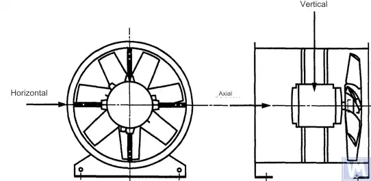
شکل ۱. موقعیت حسگر سهمختصه برای فن محوری نصبشده بهصورت افقی
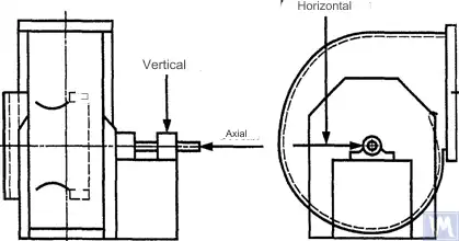
شکل ۲. موقعیت حسگر سهمختصه برای فن رادیال تکمکش
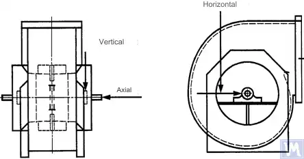
شکل ۳. موقعیت حسگر سهمختصه برای فن رادیال دو مکش
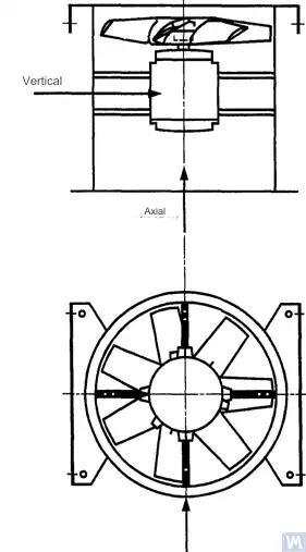
شکل ۴. موقعیت حسگر سهمختصه برای فن محوری نصبشده بهصورت عمودی
اندازهگیریها در جهت افقی باید عمود بر محور شفت انجام شوند. اندازهگیریها در جهت عمودی باید عمود بر جهت اندازهگیری افقی و عمود بر شفت فن انجام شوند. اندازهگیریها در جهت طولی باید موازی با محور شفت انجام شوند.
اندازهگیریها با استفاده از حسگرهای نوع اینرسی
تمام مقادیر ارتعاش مشخصشده در این استاندارد به اندازهگیریهایی اطلاق میشود که با استفاده از حسگرهای نوع اینرسی انجام شده و سیگنال آنها حرکت محفظه یاتاقان را بازتولید میکند.
سنسورهای مورد استفاده میتوانند شتابسنج یا حسگر سرعت باشند. باید توجه ویژهای به نصب صحیح سنسورها شود: بدون فاصله روی سطح تکیهگاه، بدون نوسان و تشدید. اندازه و جرم سنسورها و سیستم نصب نباید بیش از حد بزرگ باشد تا از تغییرات قابل توجه در ارتعاش اندازهگیریشده جلوگیری شود. مجموع خطای ناشی از روش نصب سنسور و کالیبراسیون سیستم اندازهگیری نباید از ±۱۰٪ مقدار اندازهگیریشده تجاوز کند.
اندازهگیریها با استفاده از حسگرهای بدون تماس
بر اساس توافق بین کاربر و سازنده، میتوان الزامات جابجایی حداکثر قابلقبول شفت (رجوع شود به ISO 7919-1) در یاتاقانهای لغزشی را تعیین کرد. اندازهگیریهای مربوطه را میتوان با استفاده از حسگرهای بدون تماس انجام داد.
در این حالت، سیستم اندازهگیری جابجایی سطح شفت را نسبت به بدنه یاتاقان تعیین میکند. واضح است که دامنه مجاز جابجاییها نباید از مقدار clearance یاتاقان تجاوز کند. مقدار clearance به اندازه و نوع یاتاقان، بار (محوری یا شعاعی) و جهت اندازهگیری بستگی دارد (برخی از طراحیهای یاتاقان دارای سوراخ بیضوی هستند که در آن clearance در جهت افقی بیشتر از جهت عمودی است). تنوع عواملی که باید در نظر گرفته شوند، امکان تعیین محدودیتهای یکنواخت برای جابجایی شفت را فراهم نمیکند، اما برخی توصیهها در جدول ۳ ارائه شده است. مقادیر ذکر شده در این جدول، درصد کل بازی شعاعی یاتاقان را در هر جهت نشان میدهند.
جدول ۳ – حداکثر جابجایی نسبی شفت درون یاتاقان
| وضعیت ارتعاشی فن | حداکثر جابجایی توصیهشده، درصدی از مقدار لقی (در امتداد هر محور) |
| راهاندازی/وضعیت رضایتبخش | کمتر از ۲۵٪ |
| هشدار | +50% |
| خاموشی | +70% |
| 1) مقادیر لقی شعاعی و محوری یک یاتاقان مشخص باید از تأمینکننده آن دریافت شود. | |
مقادیر دادهشده جابهجاییهای «نادرست» سطح شفت را نیز در نظر میگیرند. این جابهجاییهای «نادرست» در نتایج اندازهگیری ظاهر میشوند زیرا علاوه بر ارتعاش شفت، انحرافات مکانیکی نیز در صورتی که شفت خمیده یا غیرگرد باشد، بر این نتایج تأثیر میگذارند. هنگام استفاده از یک حسگر غیرتماسی، نتایج اندازهگیری همچنین شامل انحرافات الکتریکی خواهد بود که توسط خواص مغناطیسی و الکتریکی ماده شفت در نقطه اندازهگیری تعیین میشود. اعتقاد بر این است که در حین راهاندازی و بهرهبرداری عادی بعدی فن، محدوده مجموع انحرافات مکانیکی و الکتریکی در نقطه اندازهگیری نباید از بزرگترِ این دو مقدار تجاوز کند: 0.0125 میلیمتر یا 25٪ از مقدار جابجایی اندازهگیریشده. رانآوتها با چرخش آهسته شفت (با سرعتی بین ۲۵ تا ۴۰۰ دور در دقیقه) تعیین میشوند، زمانی که اثر نیروهای ناشی از عدم تعادل روی روتور ناچیز است. برای رسیدن به تلرانس رانآوت تعیینشده، ممکن است به ماشینکاری اضافی شفت نیاز باشد. حسگرهای بدون تماس باید، در صورت امکان، مستقیماً روی بدنه یاتاقان نصب شوند.
مقادیر حد دادهشده تنها برای فن در حالت عملیاتی نامی صدق میکند. اگر طراحی فن امکان کارکرد با سرعت دورانی متغیر را فراهم کند، به دلیل تأثیر اجتنابناپذیر تشدیدها، در سرعتهای دیگر ممکن است سطوح ارتعاش بالاتری رخ دهد.
اگر طراحی فن امکان تغییر موقعیت پرهها نسبت به جریان هوا در دهانه ورودی را فراهم کند، مقادیر دادهشده باید برای شرایطی اعمال شوند که پرهها کاملاً باز باشند. شایان ذکر است که توقف جریان هوا، بهویژه در زاویههای بزرگ پرهها نسبت به جریان ورودی، میتواند منجر به افزایش سطح ارتعاش شود.
سیستم تکیهگاه فن
وضعیت ارتعاشی فنها پس از نصب با در نظر گرفتن سختی تکیهگاه تعیین میشود. تکیهگاه زمانی صلب در نظر گرفته میشود که اولین فرکانس طبیعی سیستم «فن – تکیهگاه» از سرعت چرخشی آن بیشتر باشد. معمولاً وقتی فن روی شالودههای بتنی بزرگ نصب میشود، تکیهگاه را میتوان صلب در نظر گرفت و وقتی روی عایقهای لرزهای نصب میشود، انعطافپذیر محسوب میگردد. یک قاب فولادی که اغلب برای نصب فنها استفاده میشود، میتواند به هر یک از این دو نوع تکیهگاه تعلق داشته باشد. در صورت تردید در مورد نوع تکیهگاه فن، میتوان محاسبات یا آزمایشهایی را برای تعیین اولین فرکانس طبیعی سیستم انجام داد. در برخی موارد، تکیهگاه فن باید در یک جهت صلب و در جهتی دیگر انعطافپذیر در نظر گرفته شود.
محدودههای لرزش قابلقبول فن در آزمایشهای کارخانهای
سطوح لرزش محدودی که در جدول ۴ آمدهاند، برای فنهای مونتاژشده اعمال میشوند. این سطوح مربوط به اندازهگیریهای سرعت لرزش باند باریک در تکیهگاههای یاتاقان برای فرکانس چرخشی مورد استفاده در آزمایشهای کارخانهای هستند.
جدول ۴ – مقادیر حد لرزش در آزمونهای کارخانهای
| دستهبندی فن | حد مجاز سرعت ارتعاش RMS، mm/s | |
| تکیهگاه صلب | تکیهگاه انعطافپذیر | |
| بیوی-۱ | 9.0 | 11.2 |
| بیوی-۲ | 3.5 | 5.6 |
| بیوی-۳ | 2.8 | 3.5 |
| بیوی-۴ | 1.8 | 2.8 |
| بیوی-۵ | 1.4 | 1.8 |
| یادداشتها
1 قوانین تبدیل واحدهای سرعت ارتعاش به واحدهای جابجایی یا شتاب برای ارتعاش باند باریک در پیوست A مشخص شده است.
2 مقادیر در این جدول برای بار اسمی و فرکانس چرخشی اسمی فن که در حالت با پره های راهنمای ورودی باز کار می کند اعمال می شود. مقادیر حدی برای سایر شرایط بارگیری باید بین سازنده و مشتری توافق شود، اما توصیه می شود که بیش از 1.6 برابر از مقادیر جدولی تجاوز نکند.
|
||
محدودیتهای ارتعاش فن مجاز در حین آزمایش در محل
ارتعاش هر فن در محل بهرهبرداری آن فقط به کیفیت بالانس آن بستگی ندارد. عوامل مربوط به نصب، مانند جرم و صلبیت سیستم تکیهگاه، نیز بر آن اثر میگذارند. بنابراین، مگر آنکه در قرارداد تصریح شده باشد، سازنده فن مسئول سطح ارتعاش فن در محل بهرهبرداری آن نیست.
جدول 5 مقادیر حد توصیه شده (بر حسب واحد سرعت ارتعاش برای ارتعاش پهنای باند روی بدنه یاتاقان) را برای عملکرد عادی فن ها در دسته های مختلف ارائه می دهد.
جدول 5 – مقادیر حد ارتعاش در محل بهرهبرداری
| وضعیت ارتعاشی فن | دستهبندی فن | حد مجاز سرعت ارتعاش RMS، mm/s | |
| تکیهگاه صلب | تکیهگاه انعطافپذیر | ||
| راه اندازی | بیوی-۱ | 10 | 11.2 |
| بیوی-۲ | 5.6 | 9.0 | |
| بیوی-۳ | 4.5 | 6.3 | |
| بیوی-۴ | 2.8 | 4.5 | |
| بیوی-۵ | 1.8 | 2.8 | |
| هشدار | بیوی-۱ | 10.6 | 14.0 |
| بیوی-۲ | 9.0 | 14.0 | |
| بیوی-۳ | 7.1 | 11.8 | |
| بیوی-۴ | 4.5 | 7.1 | |
| بیوی-۵ | 4.0 | 5.6 | |
| خاموشی | بیوی-۱ | __1) | __1) |
| بیوی-۲ | __1) | __1) | |
| بیوی-۳ | 9.0 | 12.5 | |
| بیوی-۴ | 7.1 | 11.2 | |
| بیوی-۵ | 5.6 | 7.1 | |
| 1) سطح خاموشی برای فنهای دستههای BV-1 و BV-2 بر اساس تحلیل بلندمدت نتایج اندازهگیری ارتعاش تعیین میشود. | |||
ارتعاش فن های جدید در حال راه اندازی نباید از سطح "راه اندازی" تجاوز کند. همانطور که فن کار می کند، انتظار می رود سطح ارتعاش آن به دلیل فرآیندهای سایش و اثر تجمعی عوامل تأثیرگذار افزایش یابد. چنین افزایشی در ارتعاش عموماً طبیعی است و تا زمانی که به سطح "هشدار" نرسد نباید باعث نگرانی شود.
با رسیدن به سطح ارتعاش "هشدار"، بررسی علل افزایش ارتعاش و تعیین اقدامات برای کاهش آن ضروری است. عملکرد فن در این حالت باید تحت نظارت مداوم و محدود به زمان مورد نیاز برای شناسایی اقدامات برای از بین بردن علل افزایش لرزش باشد.
اگر سطح ارتعاش به سطح "خاموش" برسد، اقدامات لازم برای از بین بردن علل افزایش لرزش باید فورا انجام شود، در غیر این صورت، فن باید متوقف شود. تاخیر در رساندن سطح ارتعاش به سطح قابل قبول می تواند منجر به آسیب یاتاقان، ترک در روتور و نقاط جوشکاری محفظه فن شود و در نهایت منجر به تخریب فن شود.
هنگام ارزیابی وضعیت ارتعاش فن، نظارت بر تغییرات سطح ارتعاش در طول زمان ضروری است. تغییر ناگهانی در سطح ارتعاش نشان دهنده نیاز به بازرسی فوری فن و اقدامات تعمیر و نگهداری است. هنگام نظارت بر تغییرات ارتعاش، فرآیندهای انتقالی ناشی از، به عنوان مثال، جایگزینی روان کننده یا روش های نگهداری نباید در نظر گرفته شوند.
تأثیر روش مونتاژ
علاوه بر چرخ ها، فن ها شامل عناصر چرخشی دیگری نیز می شوند که می توانند بر سطح ارتعاش فن تأثیر بگذارند: قرقره های محرک، تسمه ها، کوپلینگ ها، روتورهای موتور یا سایر وسایل محرک. اگر شرایط سفارش نیاز به تامین فن بدون دستگاه محرک داشته باشد، ممکن است برای سازنده آزمایشهای مونتاژ برای تعیین سطوح ارتعاش غیرعملی باشد. در چنین حالتی، حتی اگر سازنده چرخ فن را متعادل کرده باشد، تا زمانی که شفت فن به درایو متصل نشود و کل دستگاه از نظر لرزش در هنگام راه اندازی تست شود، هیچ اطمینانی وجود ندارد که فن به خوبی کار کند.
معمولاً پس از مونتاژ، برای کاهش سطح ارتعاش تا حد قابلقبول، بالانس اضافی لازم است. برای همه فنهای جدید دستههای BV-3، BV-4 و BV-5، توصیه میشود پیش از راهاندازی، ارتعاش ماشین مونتاژشده اندازهگیری شود. این کار یک خط مبنا ایجاد میکند و اقدامات بعدی نگهداری را مشخص میسازد.
تولیدکنندگان فن در قبال تاثیر بر لرزش قطعات درایو نصب شده پس از تست کارخانه مسئولیتی ندارند.
ابزارهای اندازه گیری ارتعاش و کالیبراسیون
ابزار اندازه گیری
ابزار اندازه گیری و ماشین های متعادل کننده مورد استفاده باید تایید شده و الزامات کار را برآورده کنند. فاصله بین تأییدها توسط توصیه های سازنده برای ابزارهای اندازه گیری (تست) تعیین می شود. وضعیت ابزارهای اندازه گیری باید عملکرد عادی آنها را در طول دوره آزمایش تضمین کند.
پرسنلی که با ابزار اندازه گیری کار می کنند باید مهارت و تجربه کافی برای تشخیص خرابی های احتمالی و بدتر شدن کیفیت ابزار اندازه گیری داشته باشند.
کالیبراسیون
تمام ابزارهای اندازهگیری باید مطابق استانداردها کالیبره شوند. پیچیدگی فرایند کالیبراسیون میتواند از یک بازرسی فیزیکی ساده تا کالیبراسیون کل سامانه متفاوت باشد. جرمهای اصلاحیِ مورد استفاده برای تعیین نامیزانی باقیمانده طبق ISO 1940-1 را میتوان برای کالیبراسیون ابزارهای اندازهگیری نیز به کار برد.
مستندات
بالانس
در صورت درخواست، در صورت پیشبینی در شرایط قرارداد، میتوان یک گزارش تست تعادل فن به مشتری ارائه کرد که توصیه میشود شامل اطلاعات زیر باشد:
– نام سازنده دستگاه بالانس، شماره مدل؛
– نوع نصب روتور: بین تکیهگاهها یا کنسولی؛
- روش تعادل: ایستا یا پویا.
- جرم قطعات دوار مجموعه روتور؛
– عدم تعادل پسماند در هر صفحه اصلاح (از محاسبهی عدم توازن باقیمانده (ISO 21940-11) برای تعیین مقادیر قابل قبول)؛
- عدم تعادل باقیمانده مجاز در هر صفحه اصلاح.
- کلاس دقت متعادل
– معیارهای پذیرش: پذیرفته/رد شده
– گواهی تعادل (در صورت لزوم).
لرزش
در صورت درخواست، در صورت پیشبینی در شرایط قرارداد، میتوان یک گزارش تست ارتعاش فن به مشتری ارائه کرد که توصیه میشود شامل اطلاعات زیر باشد:
- ابزار اندازه گیری مورد استفاده؛
- روش اتصال سنسور ارتعاش؛
– پارامترهای کاری فن (دبی هوا، فشار، توان)؛
- فرکانس چرخش فن
- نوع پشتیبانی: صلب یا سازگار؛
– لرزش اندازه گیری شده:
1) موقعیت سنسور ارتعاش و محورهای اندازه گیری،
2) واحدهای اندازه گیری و سطوح مرجع ارتعاش،
3) محدوده فرکانس اندازه گیری (باند فرکانس باریک یا گسترده)؛
- سطح (های) ارتعاش مجاز؛
- سطح (های) ارتعاش اندازهگیری شده؛
– معیارهای پذیرش: پذیرفته/رد شده
– گواهی سطح ارتعاش (در صورت لزوم).
روش های بالانس کردن فن ها روی یک ماشین بالانس
ب.1. فن دایرکت درایو
ب.1.1. مقررات عمومی
چرخ فن که در حین مونتاژ مستقیماً روی شفت موتور نصب میشود، باید مطابق همان قاعدهای که برای در نظر گرفتن اثر شیار کلید در شفت موتور اعمال میشود، متعادل گردد.
موتورهای تولید سالهای گذشته ممکن بود با شیار کامل کلید بالانس شوند. در حال حاضر، شفتهای موتور با نیمشیار کلید بالانس میشوند، مطابق الزامات ISO 8821 (پذیرفتهشده بهعنوان GOST 31322)، و با حرف H علامتگذاری میشوند (رجوع کنید به ISO 8821).
B.1.2. موتورهای متعادلشده با شیار کامل
چرخ فن که روی شفت موتور با شیار کامل نصب شده است، باید بدون کلید روی یک شفت مخروطی متعادل شود.
B.1.3. موتورهای بالانسشده با نیمشیار
برای چرخ فن نصبشده بر روی شفت موتور که با نیمشیار متعادل شده است، گزینههای زیر امکانپذیر هستند:
الف) اگر چرخ هاب فولادی داشته باشد، پس از بالانس، یک شیار کلید در آن ایجاد کنید؛
ب) بالانس روی یک اربور مخروطی با نیمکلیدِ قراردادهشده در شیار کلید؛
ج) بالانس روی یک اربور با یک یا چند شیار کلید (رجوع کنید به B.3)، با استفاده از کلیدهای کامل.
الف) اگر چرخ هاب فولادی داشته باشد، پس از بالانس، یک شیار کلید در آن ایجاد کنید؛
ب) بالانس روی یک اربور مخروطی با نیمکلیدِ قراردادهشده در شیار کلید؛
ج) بالانس روی یک اربور با یک یا چند شیار کلید (رجوع کنید به B.3)، با استفاده از کلیدهای کامل.
B.2. فنها که توسط شفت دیگری به گردش درمیآیند
در صورت امکان، تمام اجزای چرخان، از جمله شفت فن و پولی، باید بهعنوان یک واحد واحد متعادل شوند. اگر این امر غیرعملی باشد، متعادلسازی باید روی یک اربور (رجوع کنید به B.3) با استفاده از همان قاعدهٔ احتساب شیار کلید شفت انجام شود.
B.3. اربور
میلهای که چرخ فن در حین بالانس روی آن نصب میشود باید شرایط زیر را داشته باشد:
الف) تا حد امکان سبک باشد؛
ب) در وضعیت متعادلی باشد که از طریق نگهداری مناسب و بازرسیهای منظم تضمین شده باشد؛
c) ترجیحاً مخروطی باشد تا خطاهای ناشی از عدم هممرکزی، که از تلرانسهای سوراخ هاب و ابعاد میلک ناشی میشوند، کاهش یابد. اگر میلک مخروطی باشد، موقعیت واقعی سطوح اصلاحی نسبت به یاتاقانها باید در محاسبات عدم تعادل در نظر گرفته شود.
اگر لازم باشد از شفت استوانهای استفاده شود، باید شیار کلیدی در آن ایجاد شود تا کلید کامل در آن قرار گیرد و گشتاور از شفت به چرخ فن منتقل شود.
گزینهٔ دیگر این است که دو شیار کلید در دو انتهای قطر شفت ایجاد کنید تا بتوان از روش بالانس معکوس استفاده کرد. این روش شامل مراحل زیر است. ابتدا با قرار دادن یک کلید کامل در یک شیار و یک نیمکلید در شیار دیگر، عدم تعادل چرخ را اندازهگیری کنید. سپس چرخ را نسبت به میل 180° بچرخانید و دوباره عدم تعادل آن را اندازهگیری کنید. تفاوت بین این دو مقدار عدم توازن ناشی از عدم توازن باقیماندهٔ شفت و مفصل محرک جهانی است. برای بهدستآوردن مقدار واقعی عدم توازن روتور، نیمی از اختلاف این دو اندازهگیری را محاسبه کنید.
منابع لرزش فن
در داخل فن منابع زیادی از ارتعاش وجود دارد و ارتعاش در فرکانسهای خاص میتواند مستقیماً با ویژگیهای طراحی مشخصی از ماشین مرتبط باشد. این ضمیمه تنها رایجترین منابع ارتعاش مشاهدهشده در اکثر انواع فنها را پوشش میدهد. قاعده کلی این است که هرگونه شل بودن در سیستم پشتیبانی باعث وخامت وضعیت ارتعاشی فن میشود.
نامتعادل بودن فن
این منبع اصلی لرزش پنجره است؛ این توسط حضور یک مؤلفه لرزش در فرکانس چرخشی (اول هارمونیک). علت عدم تعادل این است که محور جرم چرخان خارج از مرکز یا منحرف از محور چرخش است. این می تواند توسط توزیع جرم نابرابر، مجموع تلورانس های ابعاد سوراخ هاب و شافت، خمش شافت، یا ترکیبی از این عوامل باعث شود. لرزش ناشی از عدم تعادل عمدتاً در جهت شعاعی عمل می کند.
خمیدگی موقت شفت میتواند ناشی از گرمایش مکانیکی نامتعادل – بهدلیل اصطکاک بین اجزای چرخان و ساکن – یا ماهیت الکتریکی باشد. خمیدگی دائمی میتواند ناشی از تغییرات در خواص مواد یا ناهماهنگی شفت و چرخ فن هنگام نصب جداگانه فن و موتور باشد.
در حین کار، عدم تعادل چرخ فن میتواند بهدلیل رسوب ذرات معلق در هوا افزایش یابد. هنگام کار در محیطی خورنده، عدم تعادل میتواند ناشی از فرسایش یا خوردگی نامنظم چرخ باشد.
نامتعادلی را میتوان با بالانس اضافی در راستایهای مناسب اصلاح کرد، اما پیش از انجام فرایند بالانس، منابع نامتعادلی باید شناسایی و حذف شده و پایداری ارتعاشی ماشین بررسی شود.
ناهممحوری فن و موتور
این نقص میتواند زمانی رخ دهد که شفت موتور و شفت فن از طریق یک سیستم تسمهای یا کوپلینگ انعطافپذیر به هم متصل باشند. ناهمسوئی گاهی اوقات با اجزای فرکانسی ارتعاش مشخصه قابل تشخیص است که معمولاً هارمونیکهای اول و دوم فرکانس چرخش هستند. در مورد ناهمسوئی موازی شفتها، ارتعاش عمدتاً در جهت شعاعی رخ میدهد، در حالی که اگر شفتها با زاویه قطع شوند، ارتعاش طولی ممکن است غالب شود.
اگر شفتها با زاویه به هم متصل باشند و از کوپلینگهای صلب استفاده شود، نیروهای متناوب در ماشین ایجاد میشوند که باعث افزایش سایش شفتها و کوپلینگها میگردند. این اثر را میتوان با استفاده از کوپلینگهای انعطافپذیر بهطور قابلملاحظهای کاهش داد.
لرزش فن ناشی از برانگیختگی آیرودینامیکی
تحریک لرزش می تواند توسط تعامل چرخ پنجره با عناصر ثابت طراحی، مانند بال هدایت، موتور، یا تکیه گاه های یاتاقان، مقادیر شکاف نادرست، یا ساختارهای هوای ورودی و خروجی نادرست طراحی شده باعث شود. یک ویژگی مشخصه این منابع حضور لرزش تناوبی مرتبط با فرکانس چرخشی چرخ، در پس زمینه نوسانات تصادفی در تعامل بال های چرخ با هوا است. لرزش می تواند در هارمونیک های فرکانس بال، که حاصل ضرب فرکانس چرخشی چرخ و تعداد بال های چرخ است.
ناپایداری آیرودینامیکی جریان هوا، ناشی از جداشدن جریان از سطح پره و تشکیل گردابهای متعاقب، باعث ایجاد ارتعاشات پهنباند میشود که شکل طیف آن بسته به بار فن تغییر میکند.
نویز آیرودینامیکی با این ویژگی مشخص میشود که به فرکانس چرخش چرخ مربوط نیست و میتواند در زیرهارمونیکهای فرکانس چرخش (یعنی فرکانسهایی پایینتر از فرکانس چرخش) رخ دهد. در این حالت، ارتعاش قابلتوجهی در بدنهٔ فن و کانالها مشاهده میشود.
اگر سیستم آیرودینامیکی فن بهخوبی با مشخصات آن مطابقت نداشته باشد، ضربههای شدیدی ممکن است در آن رخ دهد. این ضربهها بهراحتی با گوش قابل تشخیص هستند و بهعنوان تکانه به سیستم پشتیبانی فن منتقل میشوند.
اگر علل فوقالذکر منجر به لرزش تیغه شوند، میتوان ماهیت آن را با نصب حسگرها در نقاط مختلف سازه بررسی کرد.
لرزش فن ناشی از چرخش در لایه روغن
ویرلهایی که ممکن است در لایه روانکاری یاتاقانهای لغزشی رخ دهند، در فرکانس مشخصهای اندکی پایینتر از فرکانس چرخشی روتور مشاهده میشوند، مگر آنکه فن با سرعتی بالاتر از نخستین سرعت بحرانی کار کند. در حالت دوم، ناپایداری گوه روغن در نخستین سرعت بحرانی مشاهده میشود و گاهی این اثر را ویرل تشدیدی مینامند.
منابع ارتعاش فن با منشأ الکتریکی
گرمایش نامنظم روتور موتور میتواند باعث انحنا آن شود و به عدم تعادل (که در هارمونیک اول ظاهر میشود) منجر گردد.
در مورد موتور آسنکرون، وجود یک مولفه با فرکانسی برابر با فرکانس چرخش ضربدر تعداد صفحات روتور، نشاندهنده نقصهای مربوط به صفحات استاتور است و بالعکس، مولفههایی با فرکانسی برابر با فرکانس چرخش ضربدر تعداد صفحات روتور، نشاندهنده نقصهای مربوط به صفحات روتور هستند.
بسیاری از مؤلفههای ارتعاشی با ماهیت الکتریکی با ناپدید شدن فوری خود هنگام قطع منبع تغذیه مشخص میشوند.
لرزش فن ناشی از تحریک توسط سیستم تسمهای
بهطور کلی، دو نوع مشکل در رابطه با سیستمهای انتقال نیرو با تسمه وجود دارد: زمانی که عملکرد سیستم تحت تأثیر نقصهای خارجی قرار میگیرد و زمانی که نقصها در خود تسمه وجود دارند.
در مورد اول، اگرچه تسمه میلرزد، این به دلیل نیروهای تحمیلی از منابع دیگر است، بنابراین تعویض تسمه نتایج مطلوب را به همراه نخواهد داشت. منابع رایج این نیروها شامل عدم تعادل در سیستم محرک، نامرکز بودن قرقره، ناهمسوئی و شل شدن اتصالات مکانیکی هستند. بنابراین، پیش از تعویض تسمهها باید تحلیل ارتعاش انجام شود تا منبع تحریک شناسایی گردد.
اگر تسمهها به نیروهای خارجی وارد پاسخ دهند، فرکانس ارتعاش آنها به احتمال زیاد برابر فرکانس تحریک خواهد بود. در این حالت میتوان فرکانس تحریک را با استفاده از لامپ استروبوسکوپ تعیین کرد و آن را طوری تنظیم نمود که تسمه در نور لامپ ثابت به نظر برسد.
در سامانههای انتقال چندتسمهای، نابرابری کشش تسمهها میتواند به افزایش قابلتوجه ارتعاش منتقلشده منجر شود.
مواردی که منابع ارتعاش خودِ تسمهها هستند، به نقصهای فیزیکی آنها مربوط میشوند: ترکها، نقاط سخت و نرم، آلودگی روی سطح تسمه، فقدان ماده از سطح آن و غیره. برای تسمههای V، تغییر در عرض آنها باعث میشود تسمه روی شیار پولی بالا و پایین برود و بهدلیل تغییر در تنش، ارتعاش ایجاد شود.
اگر منبع ارتعاش خود تسمه باشد، فرکانسهای ارتعاش معمولاً هارمونیکهای فرکانس چرخشی تسمه هستند. در یک مورد خاص، فرکانس تحریک به ماهیت نقص و تعداد پولیها، از جمله تنشدهندهها، بستگی دارد.
در برخی موارد، دامنه ارتعاش ممکن است ناپایدار باشد. این موضوع بهویژه در سامانههای انتقال چندتسمهای صادق است.
عیوب مکانیکی و الکتریکی منشأ ارتعاش هستند که متعاقباً به صدای هوایی تبدیل میشوند. نویز مکانیکی میتواند با عدم تعادل فن یا موتور، صدای یاتاقان، هممحوری محور، ارتعاشات دیوار کانال و پنلهای بدنه، ارتعاشات تیغه دمپر، ارتعاشات تیغه، دمپر، لوله و تکیهگاه و همچنین انتقال ارتعاشات مکانیکی از طریق سازه مرتبط باشد. نویز الکتریکی با اشکال مختلف تبدیل انرژی الکتریکی مرتبط است: ۱) نیروهای مغناطیسی توسط چگالی جریان مغناطیسی، تعداد و شکل قطبها و هندسه شکاف هوایی تعیین میشوند؛ ۲) نویز الکتریکی تصادفی توسط برسها، قوس الکتریکی، جرقههای الکتریکی و غیره تعیین میشود.
سر و صدای آیرودینامیکی میتواند با تشکیل گرداب، نوسانات فشار، مقاومت هوا و غیره مرتبط باشد و میتواند ماهیت پهنباند و باریکباند داشته باشد. نویز پهنباند میتواند ناشی از: الف) پرهها، دمپرها و سایر موانع در مسیر جریان هوا؛ ب) چرخش فن بهطور کلی، تسمهها، شکافها و غیره؛ ج) تغییرات ناگهانی در جهت جریان هوا یا مقطع کانال، تفاوتهای سرعت جریان، جدایی جریان بهدلیل اثرات مرزی، اثرات تراکم جریان و غیره. نویز باند باریک میتواند ناشی از موارد زیر باشد: الف) تشدیدها (اثر لولههای ارگ، ارتعاشات سیمها، ارتعاشات پنل، عناصر سازهای و غیره)؛ ب) تشکیل گرداب در لبههای تیز (برانگیختگی ستون هوا)؛ ج) دورانها (اثر شیپور، شکافها، سوراخها، شیارها روی قطعات چرخان).
ضربه هایی که در اثر تماس بین عناصر مکانیکی مختلف سازه ایجاد می شود، صدایی مشابه صدای ناشی از ضربه چکش، غلتیدن رعد، جعبه خالی طنین انداز و غیره ایجاد می کند. تکانه های ضربه می توانند به قدری زودگذر باشند که برای تشخیص تکانه های ضربه دوره ای از فرآیندهای گذرا، تجهیزات ضبط با سرعت بالا مورد نیاز است. ناحیه ای که بسیاری از تکانه های ضربه ای در آن رخ می دهد، روی هم قرار گرفتن قله های آنها یک اثر زمزمه ثابت ایجاد می کند.
وابستگی ارتعاش به نوع پشتیبانی فن
انتخاب صحیح تکیه گاه فن یا طراحی فونداسیون برای عملکرد روان و بدون مشکل آن ضروری است. برای اطمینان از تراز اجزای دوار هنگام نصب فن، موتور و سایر دستگاه های محرک، از یک قاب فولادی یا پایه بتن مسلح استفاده می شود. گاهی اوقات تلاش برای صرفه جویی در ساخت پشتیبانی منجر به ناتوانی در حفظ تراز مورد نیاز اجزای ماشین می شود. این امر به ویژه زمانی که ارتعاش به تغییرات هم ترازی حساس است، غیرقابل قبول است، به ویژه برای ماشینهایی که از قطعات جداگانهای تشکیل شدهاند که توسط بستهای فلزی به هم متصل شدهاند.
پایه ای که پایه روی آن گذاشته می شود نیز می تواند بر لرزش فن و موتور تأثیر بگذارد. اگر فرکانس طبیعی فونداسیون به فرکانس چرخش فن یا موتور نزدیک باشد، فونداسیون در حین کار فن طنین انداز می شود. این را می توان با اندازه گیری ارتعاش در چندین نقطه در سراسر فونداسیون، کف اطراف و تکیه گاه های فن تشخیص داد. اغلب در شرایط رزونانس، جزء ارتعاش عمودی به طور قابل توجهی از افقی فراتر می رود. لرزش را می توان با سفت تر کردن پایه یا افزایش جرم آن کاهش داد. حتی اگر عدم تعادل و ناهماهنگی از بین برود و امکان کاهش نیروهای اجباری فراهم شود، ممکن است پیششرطهای ارتعاشی قابل توجهی همچنان وجود داشته باشد. این بدان معناست که اگر فن همراه با تکیه گاه آن به رزونانس نزدیک باشد، دستیابی به مقادیر قابل قبول ارتعاش مستلزم متعادلسازی دقیقتر و تراز محوری دقیقتری نسبت به این ماشینها خواهد بود. این وضعیت نامطلوب است و باید با افزایش جرم و/یا سختی تکیه گاه یا بلوک بتنی از آن جلوگیری کرد.
راهنمای مانیتورینگ و تشخیص وضعیت ارتعاش
اصل اصلی پایش وضعیت ارتعاش ماشین (که از این پس «وضعیت» نامیده میشود) این است که نتایج اندازهگیریهای بهدرستی برنامهریزیشده مشاهده شوند تا روند افزایش سطوح ارتعاش شناسایی و از منظر مشکلات بالقوه بررسی شود. پایش در شرایطی کاربرد دارد که آسیب بهآرامی ایجاد میشود و افت وضعیت مکانیزم از طریق نشانههای فیزیکی قابلاندازهگیری بروز میکند.
ارتعاش فن، ناشی از ایجاد نقص های فیزیکی، می تواند در فواصل زمانی معینی نظارت شود و زمانی که افزایش سطح ارتعاش تشخیص داده شود، فرکانس مشاهده می تواند افزایش یابد و تجزیه و تحلیل وضعیت دقیق انجام شود. در این مورد، علل تغییرات ارتعاش را می توان بر اساس تجزیه و تحلیل فرکانس ارتعاش، که امکان تعیین اقدامات لازم و برنامه ریزی اجرای آنها را مدت ها قبل از شدید شدن آسیب، شناسایی کرد. معمولاً زمانی که سطح ارتعاش 1.6 برابر یا 4 دسی بل در مقایسه با سطح پایه افزایش می یابد، اقدامات لازم در نظر گرفته می شود.
برنامه پایش وضعیت شامل چند مرحله است که می توان به طور خلاصه به صورت زیر فرموله کرد:
- الف) شناسایی وضعیت فن و تعیین سطح ارتعاش پایه (ممکن است با سطح به دست آمده در طول آزمایشات کارخانه به دلیل روش های مختلف نصب و غیره متفاوت باشد).
- ب) نقاط اندازه گیری ارتعاش را انتخاب کنید.
- ج) فرکانس مشاهده (اندازه گیری) را تعیین کنید.
- د) روش ثبت اطلاعات را ایجاد کنید.
- ه) معیارهای ارزیابی وضعیت ارتعاش فن، مقادیر حدی برای ارتعاش مطلق و تغییرات ارتعاش را تعیین کنید، تجربه کار با ماشین های مشابه را خلاصه کنید.
از آنجا که فنها معمولاً در سرعتهایی که به سرعت بحرانی نزدیک نیستند بدون مشکل کار میکنند، سطح ارتعاش نباید با تغییرات جزئی سرعت یا بار بهطور قابلتوجهی تغییر کند. با این حال، توجه به این نکته مهم است که وقتی فن با سرعت چرخشی متغیر کار میکند، مقادیر حد ارتعاش تعیینشده برای حداکثر سرعت چرخشی کاری اعمال میشوند. اگر نتوان در چارچوب این حدود ارتعاش به حداکثر سرعت چرخشی کاری رسید، این امر میتواند نشاندهنده وجود یک مشکل جدی باشد و به بررسی ویژه نیاز داشته باشد.
برخی از توصیههای تشخیصی ارائهشده در ضمیمه C بر اساس تجربه عملکرد فن هستند و برای کاربرد متوالی در هنگام تجزیه و تحلیل علل افزایش لرزش در نظر گرفته شدهاند.
برای ارزیابی کیفی ارتعاش یک فن خاص و تعیین دستورالعملهایی برای اقدامات بعدی، میتوان از مرزهای منطقه شرایط ارتعاش تعیین شده توسط ISO 10816-1 استفاده کرد.
انتظار می رود که برای فن های جدید، سطوح ارتعاش آنها کمتر از مقادیر حدی ارائه شده در جدول 3 باشد. این مقادیر مطابق با مرز منطقه A شرایط ارتعاش مطابق ISO 10816-1 است. مقادیر توصیه شده برای سطوح هشدار و خاموشی بر اساس تجزیه و تحلیل اطلاعات جمع آوری شده بر روی انواع خاصی از فن ها ایجاد می شود.
اطلاعات مطابقت
مرجع استانداردهای بین المللی که به عنوان مراجع هنجاری در این استاندارد استفاده می شود
جدول H.1
|
تعیین استاندارد بین ایالتی مرجع
|
تعیین و عنوان استاندارد بین المللی مرجع و تعیین مشروط درجه انطباق آن با استاندارد بین ایالتی مرجع
|
|
GOST ISO 1940-1-2007
|
ISO 1940-1:1986. لرزش. الزامات برای کیفیت متعادل کننده روتورهای صلب. قسمت 1. تعیین عدم تعادل مجاز (IDT)
|
|
GOST ISO 5348-2002
|
ISO 5348:1999. لرزش و شوک. نصب مکانیکی شتاب سنج ها (IDT)
|
|
GOST ISO 7919-1-2002
|
ISO 7919-1:1996. لرزش ماشین های غیر رفت و برگشتی. اندازه گیری شفت های دوار و معیارهای ارزیابی. بخش 1. دستورالعمل های عمومی (IDT)
|
|
GOST ISO 10816-1-97
|
ISO 10816-1:1995. لرزش. ارزیابی وضعیت ماشین با اندازه گیری ارتعاش در قطعات غیر چرخان. بخش 1. دستورالعمل های عمومی (IDT)
|
|
GOST ISO 10816-3-2002
|
ISO 10816-3:1998. لرزش. ارزیابی وضعیت ماشین با اندازه گیری ارتعاش در قطعات غیر چرخان. قسمت 3. ماشین های صنعتی با توان اسمی بیش از 15 کیلو وات و سرعت های اسمی 120 تا 15000 دور در دقیقه، اندازه گیری درجا (IDT)
|
|
GOST 10921-90
|
ISO 5801:1997. فن های صنعتی تست عملکرد با استفاده از کانال های استاندارد (NEQ)
|
|
GOST 19534-74
|
ISO 1925:2001. لرزش. متعادل کردن. واژگان (NEQ)
|
|
GOST 24346-80
|
ISO 2041:1990. لرزش و شوک. واژگان (NEQ)
|
|
GOST 31322-2006 (ISO 8821:1989)
|
ISO 8821:1989. لرزش. متعادل کردن. رهنمودهایی برای حسابداری اثر کلید در هنگام متعادل کردن شفت ها و قطعات نصب شده (MOD)
|
|
GOST 31351-2007 (ISO 14695:2003)
|
ISO 14695:2003. فن های صنعتی روشهای اندازهگیری ارتعاش (MOD)
|
|
توجه: تعیینهای مشروط زیر درجه انطباق استاندارد در این جدول استفاده میشود: IDT – استانداردهای یکسان.
|
|
0 Comments