ਆਪਣੇ ਹੱਥੀਂ ਸੰਤੁਲਨ ਮਸ਼ੀਨਾਂ
ਪੇਸ਼ੇਵਰ-ਗ੍ਰੇਡ ਬੈਲੈਂਸਿੰਗ ਮਸ਼ੀਨਾਂ ਬਣਾਉਣ ਲਈ ਵਿਸਤ੍ਰਿਤ ਤਕਨੀਕੀ ਗਾਈਡ। ਸਾਫ਼ਟ ਬੇਅਰਿੰਗ ਬਨਾਮ ਹਾਰਡ ਬੇਅਰਿੰਗ ਡਿਜ਼ਾਈਨ, ਸਪਿੰਡਲ ਗਣਨਾਵਾਂ, ਸਪੋਰਟ ਸਿਸਟਮ ਅਤੇ ਮਾਪਣ ਵਾਲੇ ਉਪਕਰਣ ਏਕੀਕਰਨ ਬਾਰੇ ਜਾਣੋ।
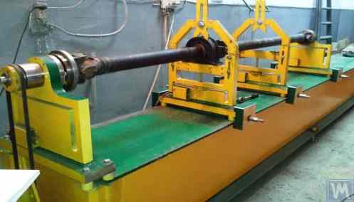
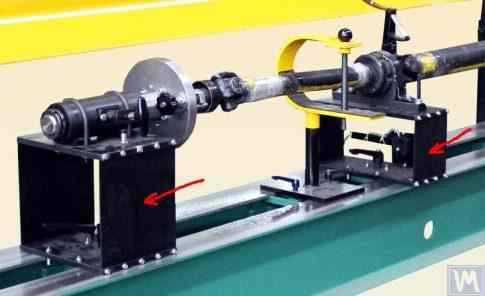
ਵਿਸ਼ਾ-ਸੂਚੀ







1. ਜਾਣ-ਪਛਾਣ
(ਇਹ ਕੰਮ ਲਿਖਣ ਦੀ ਲੋੜ ਕਿਉਂ ਪਈ?)
LLC "Kinematics" (Vibromera) ਦੁਆਰਾ ਨਿਰਮਿਤ ਬੈਲੈਂਸਿੰਗ ਯੰਤਰਾਂ ਦੀ ਖਪਤ ਬਣਤਰ ਦੇ ਵਿਸ਼ਲੇਸ਼ਣ ਤੋਂ ਪਤਾ ਲੱਗਦਾ ਹੈ ਕਿ ਇਹਨਾਂ ਵਿੱਚੋਂ ਲਗਭਗ 30% ਬੈਲੈਂਸਿੰਗ ਮਸ਼ੀਨਾਂ ਅਤੇ/ਜਾਂ ਸਟੈਂਡਾਂ ਲਈ ਸਥਾਈ ਮਾਪਣ ਅਤੇ ਗਣਨਾ ਪ੍ਰਣਾਲੀਆਂ ਵਜੋਂ ਵਰਤੋਂ ਲਈ ਖਰੀਦੇ ਜਾਂਦੇ ਹਨ। ਸਾਡੇ ਉਪਕਰਣਾਂ ਦੇ ਖਪਤਕਾਰਾਂ (ਗਾਹਕਾਂ) ਦੇ ਦੋ ਸਮੂਹਾਂ ਦੀ ਪਛਾਣ ਕਰਨਾ ਸੰਭਵ ਹੈ।
ਪਹਿਲੇ ਸਮੂਹ ਵਿੱਚ ਉਹ ਉੱਦਮ ਸ਼ਾਮਲ ਹਨ ਜੋ ਬੈਲੇਂਸਿੰਗ ਮਸ਼ੀਨਾਂ ਦੇ ਵੱਡੇ ਪੱਧਰ 'ਤੇ ਉਤਪਾਦਨ ਅਤੇ ਉਹਨਾਂ ਨੂੰ ਬਾਹਰੀ ਗਾਹਕਾਂ ਨੂੰ ਵੇਚਣ ਵਿੱਚ ਮਾਹਰ ਹਨ। ਇਹ ਉੱਦਮ ਵੱਖ-ਵੱਖ ਕਿਸਮਾਂ ਦੀਆਂ ਬੈਲੇਂਸਿੰਗ ਮਸ਼ੀਨਾਂ ਨੂੰ ਡਿਜ਼ਾਈਨ ਕਰਨ, ਬਣਾਉਣ ਅਤੇ ਚਲਾਉਣ ਵਿੱਚ ਡੂੰਘੇ ਗਿਆਨ ਅਤੇ ਵਿਆਪਕ ਤਜਰਬੇ ਵਾਲੇ ਉੱਚ ਯੋਗਤਾ ਪ੍ਰਾਪਤ ਮਾਹਰਾਂ ਨੂੰ ਨਿਯੁਕਤ ਕਰਦੇ ਹਨ। ਇਸ ਸਮੂਹ ਦੇ ਖਪਤਕਾਰਾਂ ਨਾਲ ਗੱਲਬਾਤ ਵਿੱਚ ਪੈਦਾ ਹੋਣ ਵਾਲੀਆਂ ਚੁਣੌਤੀਆਂ ਅਕਸਰ ਸਾਡੀਆਂ ਮਾਪਣ ਪ੍ਰਣਾਲੀਆਂ ਅਤੇ ਸਾਫਟਵੇਅਰ ਨੂੰ ਮੌਜੂਦਾ ਜਾਂ ਨਵੀਆਂ ਵਿਕਸਿਤ ਮਸ਼ੀਨਾਂ ਦੇ ਅਨੁਕੂਲ ਬਣਾਉਣ ਨਾਲ ਸਬੰਧਤ ਹੁੰਦੀਆਂ ਹਨ, ਬਿਨਾਂ ਉਹਨਾਂ ਦੇ ਢਾਂਚਾਗਤ ਨਿਰਮਾਣ ਦੇ ਮੁੱਦਿਆਂ ਨੂੰ ਸੰਬੋਧਿਤ ਕੀਤੇ।
ਦੂਜੇ ਸਮੂਹ ਵਿੱਚ ਉਹ ਖਪਤਕਾਰ ਸ਼ਾਮਲ ਹਨ ਜੋ ਆਪਣੀਆਂ ਲੋੜਾਂ ਲਈ ਮਸ਼ੀਨਾਂ (ਸਟੈਂਡ) ਵਿਕਸਿਤ ਅਤੇ ਨਿਰਮਾਣ ਕਰਦੇ ਹਨ। ਇਸ ਪਹੁੰਚ ਦੀ ਵਿਆਖਿਆ ਜ਼ਿਆਦਾਤਰ ਸੁਤੰਤਰ ਨਿਰਮਾਤਾਵਾਂ ਦੀ ਆਪਣੀ ਉਤਪਾਦਨ ਲਾਗਤ ਘਟਾਉਣ ਦੀ ਇੱਛਾ ਨਾਲ ਕੀਤੀ ਜਾਂਦੀ ਹੈ, ਜੋ ਕੁਝ ਮਾਮਲਿਆਂ ਵਿੱਚ ਦੋ ਤੋਂ ਤਿੰਨ ਗੁਣਾ ਜਾਂ ਵੱਧ ਘੱਟ ਸਕਦੀ ਹੈ। ਇਸ ਸਮੂਹ ਦੇ ਖਪਤਕਾਰਾਂ ਕੋਲ ਅਕਸਰ ਮਸ਼ੀਨਾਂ ਬਣਾਉਣ ਦਾ ਸਹੀ ਤਜਰਬਾ ਨਹੀਂ ਹੁੰਦਾ ਅਤੇ ਉਹ ਆਮ ਤੌਰ 'ਤੇ ਆਪਣੇ ਕੰਮ ਵਿੱਚ ਸਾਧਾਰਨ ਸੂਝ, ਇੰਟਰਨੈੱਟ ਤੋਂ ਜਾਣਕਾਰੀ, ਅਤੇ ਕਿਸੇ ਵੀ ਉਪਲਬਧ ਸਮਾਨ ਉਦਾਹਰਣਾਂ 'ਤੇ ਨਿਰਭਰ ਕਰਦੇ ਹਨ।
ਉਹਨਾਂ ਨਾਲ ਗੱਲਬਾਤ ਕਰਨ ਨਾਲ ਕਈ ਸਵਾਲ ਪੈਦਾ ਹੁੰਦੇ ਹਨ, ਜੋ ਬੈਲੇਂਸਿੰਗ ਮਸ਼ੀਨਾਂ ਦੀਆਂ ਮਾਪਣ ਪ੍ਰਣਾਲੀਆਂ ਬਾਰੇ ਵਾਧੂ ਜਾਣਕਾਰੀ ਤੋਂ ਇਲਾਵਾ, ਮਸ਼ੀਨਾਂ ਦੇ ਢਾਂਚਾਗਤ ਨਿਰਮਾਣ, ਨੀਂਹ 'ਤੇ ਉਹਨਾਂ ਦੀ ਸਥਾਪਨਾ ਦੇ ਢੰਗਾਂ, ਡਰਾਈਵਾਂ ਦੀ ਚੋਣ, ਅਤੇ ਸਹੀ ਬੈਲੇਂਸਿੰਗ ਸ਼ੁੱਧਤਾ ਪ੍ਰਾਪਤ ਕਰਨ ਆਦਿ ਨਾਲ ਸਬੰਧਤ ਮੁੱਦਿਆਂ ਦੀ ਇੱਕ ਵਿਆਪਕ ਲੜੀ ਨੂੰ ਕਵਰ ਕਰਦੇ ਹਨ।
ਬੈਲੈਂਸਿੰਗ ਮਸ਼ੀਨਾਂ ਦੇ ਸੁਤੰਤਰ ਨਿਰਮਾਣ ਦੇ ਮੁੱਦਿਆਂ ਵਿੱਚ ਸਾਡੇ ਗਾਹਕਾਂ ਦੇ ਇੱਕ ਵੱਡੇ ਸਮੂਹ ਵੱਲੋਂ ਦਿਖਾਈ ਗਈ ਮਹੱਤਵਪੂਰਨ ਦਿਲਚਸਪੀ ਨੂੰ ਧਿਆਨ ਵਿੱਚ ਰੱਖਦੇ ਹੋਏ, LLC "Kinematics" (Vibromera) ਦੇ ਮਾਹਿਰਾਂ ਨੇ ਸਭ ਤੋਂ ਵੱਧ ਪੁੱਛੇ ਜਾਣ ਵਾਲੇ ਸਵਾਲਾਂ ਬਾਰੇ ਟਿੱਪਣੀਆਂ ਅਤੇ ਸਿਫ਼ਾਰਸ਼ਾਂ ਦੇ ਨਾਲ ਇੱਕ ਸੰਗ੍ਰਹਿ ਤਿਆਰ ਕੀਤਾ ਹੈ।
2. ਬੈਲੇਂਸਿੰਗ ਮਸ਼ੀਨਾਂ (ਸਟੈਂਡਾਂ) ਦੀਆਂ ਕਿਸਮਾਂ ਅਤੇ ਉਹਨਾਂ ਦੀਆਂ ਡਿਜ਼ਾਈਨ ਵਿਸ਼ੇਸ਼ਤਾਵਾਂ
ਬੈਲੈਂਸਿੰਗ ਮਸ਼ੀਨ ਇੱਕ ਤਕਨੀਕੀ ਯੰਤਰ ਹੈ ਜੋ ਵੱਖ-ਵੱਖ ਉਦੇਸ਼ਾਂ ਲਈ ਰੋਟਰਾਂ ਦੇ ਸਥਿਰ ਜਾਂ ਗਤੀਸ਼ੀਲ ਅਸੰਤੁਲਨ ਨੂੰ ਖ਼ਤਮ ਕਰਨ ਲਈ ਤਿਆਰ ਕੀਤਾ ਗਿਆ ਹੈ। ਇਸ ਵਿੱਚ ਇੱਕ ਵਿਧੀ ਸ਼ਾਮਲ ਹੈ ਜੋ ਬੈਲੰਸ ਕੀਤੇ ਜਾ ਰਹੇ ਰੋਟਰ ਨੂੰ ਇੱਕ ਨਿਸ਼ਚਿਤ ਘੁੰਮਣ ਬਾਰੰਬਾਰਤਾ ਤੱਕ ਤੇਜ਼ ਕਰਦੀ ਹੈ, ਅਤੇ ਇੱਕ ਵਿਸ਼ੇਸ਼ ਮਾਪਣ ਅਤੇ ਗਣਨਾ ਪ੍ਰਣਾਲੀ ਜੋ ਰੋਟਰ ਦੇ ਅਸੰਤੁਲਨ ਦੀ ਭਰਪਾਈ ਲਈ ਲੋੜੀਂਦੇ ਸੁਧਾਰਕ ਵਜ਼ਨਾਂ ਦੇ ਪੁੰਜ ਅਤੇ ਸਥਾਨ ਨਿਰਧਾਰਤ ਕਰਦੀ ਹੈ।
ਮਸ਼ੀਨ ਦੇ ਮਕੈਨੀਕਲ ਹਿੱਸੇ ਦੀ ਬਣਤਰ ਵਿੱਚ ਆਮ ਤੌਰ 'ਤੇ ਇੱਕ ਬੈੱਡਫ੍ਰੇਮ ਹੁੰਦਾ ਹੈ ਜਿਸ 'ਤੇ ਸਪੋਰਟ ਪੋਸਟਾਂ (ਬੇਅਰਿੰਗਾਂ) ਲਗਾਈਆਂ ਜਾਂਦੀਆਂ ਹਨ। ਇਹ ਬੈਲੈਂਸ ਕੀਤੇ ਜਾਣ ਵਾਲੇ ਉਤਪਾਦ (ਰੋਟਰ) ਨੂੰ ਮਾਊਂਟ ਕਰਨ ਲਈ ਵਰਤੀਆਂ ਜਾਂਦੀਆਂ ਹਨ ਅਤੇ ਰੋਟਰ ਨੂੰ ਘੁੰਮਾਉਣ ਲਈ ਇੱਕ ਡਰਾਈਵ ਸ਼ਾਮਲ ਕਰਦੀਆਂ ਹਨ। ਬੈਲੈਂਸਿੰਗ ਪ੍ਰਕਿਰਿਆ ਦੌਰਾਨ, ਜੋ ਉਤਪਾਦ ਦੇ ਘੁੰਮਦੇ ਸਮੇਂ ਕੀਤੀ ਜਾਂਦੀ ਹੈ, ਮਾਪਣ ਪ੍ਰਣਾਲੀ ਦੇ ਸੈਂਸਰ (ਜਿਨ੍ਹਾਂ ਦੀ ਕਿਸਮ ਮਸ਼ੀਨ ਦੇ ਡਿਜ਼ਾਈਨ 'ਤੇ ਨਿਰਭਰ ਕਰਦੀ ਹੈ) ਜਾਂ ਤਾਂ ਬੇਅਰਿੰਗਾਂ ਵਿੱਚ ਵਾਈਬ੍ਰੇਸ਼ਨਾਂ ਜਾਂ ਬੇਅਰਿੰਗਾਂ 'ਤੇ ਪੈਣ ਵਾਲੀਆਂ ਸ਼ਕਤੀਆਂ ਨੂੰ ਦਰਜ ਕਰਦੇ ਹਨ।
ਇਸ ਤਰੀਕੇ ਨਾਲ ਪ੍ਰਾਪਤ ਕੀਤਾ ਗਿਆ ਡਾਟਾ ਅਸੰਤੁਲਨ ਦੀ ਭਰਪਾਈ ਕਰਨ ਲਈ ਲੋੜੀਂਦੇ ਸੁਧਾਰ ਵਜ਼ਨਾਂ ਦੇ ਪੁੰਜ ਅਤੇ ਸਥਾਪਨਾ ਸਥਾਨਾਂ ਨੂੰ ਨਿਰਧਾਰਤ ਕਰਨ ਦੀ ਇਜਾਜ਼ਤ ਦਿੰਦਾ ਹੈ।
ਵਰਤਮਾਨ ਵਿੱਚ, ਬੈਲੇਂਸਿੰਗ ਮਸ਼ੀਨ (ਸਟੈਂਡ) ਡਿਜ਼ਾਈਨਾਂ ਦੀਆਂ ਦੋ ਕਿਸਮਾਂ ਸਭ ਤੋਂ ਵੱਧ ਪ੍ਰਚਲਿਤ ਹਨ:
- ਸਾਫਟ ਬੇਅਰਿੰਗ ਮਸ਼ੀਨਾਂ (ਲਚਕਦਾਰ ਸਪੋਰਟਾਂ ਦੇ ਨਾਲ);
- ਹਾਰਡ ਬੇਅਰਿੰਗ ਮਸ਼ੀਨਾਂ (ਸਖ਼ਤ ਸਪੋਰਟਾਂ ਦੇ ਨਾਲ)।
2.1. ਸਾਫਟ ਬੇਅਰਿੰਗ ਮਸ਼ੀਨਾਂ ਅਤੇ ਸਟੈਂਡ
ਸਾਫਟ ਬੇਅਰਿੰਗ ਬੈਲੇਂਸਿੰਗ ਮਸ਼ੀਨਾਂ (ਸਟੈਂਡਾਂ) ਦੀ ਬੁਨਿਆਦੀ ਵਿਸ਼ੇਸ਼ਤਾ ਇਹ ਹੈ ਕਿ ਉਹਨਾਂ ਵਿੱਚ ਮੁਕਾਬਲਤਨ ਲਚਕਦਾਰ ਸਪੋਰਟ ਹੁੰਦੇ ਹਨ, ਜੋ ਸਪਰਿੰਗ ਸਸਪੈਂਸ਼ਨਾਂ, ਸਪਰਿੰਗ-ਮਾਊਂਟਡ ਕੈਰੇਜਾਂ, ਫਲੈਟ ਜਾਂ ਸਿਲੰਡਰਿਕ ਸਪਰਿੰਗ ਸਪੋਰਟਾਂ ਆਦਿ ਦੇ ਆਧਾਰ 'ਤੇ ਬਣਾਏ ਜਾਂਦੇ ਹਨ। ਇਹਨਾਂ ਸਪੋਰਟਾਂ ਦੀ ਕੁਦਰਤੀ ਬਾਰੰਬਾਰਤਾ ਉਹਨਾਂ 'ਤੇ ਲੱਗੇ ਬੈਲੇਂਸ ਕੀਤੇ ਜਾਣ ਵਾਲੇ ਰੋਟਰ ਦੀ ਘੁੰਮਣ ਬਾਰੰਬਾਰਤਾ ਤੋਂ ਘੱਟੋ-ਘੱਟ 2-3 ਗੁਣਾ ਘੱਟ ਹੁੰਦੀ ਹੈ। ਲਚਕਦਾਰ ਸਾਫਟ ਬੇਅਰਿੰਗ ਸਪੋਰਟਾਂ ਦੇ ਢਾਂਚਾਗਤ ਨਿਰਮਾਣ ਦੀ ਇੱਕ ਕਲਾਸਿਕ ਉਦਾਹਰਣ ਮਸ਼ੀਨ ਮਾਡਲ DB-50 ਦੇ ਸਪੋਰਟ ਵਿੱਚ ਦੇਖੀ ਜਾ ਸਕਦੀ ਹੈ, ਜਿਸਦੀ ਫੋਟੋ ਚਿੱਤਰ 2.1 ਵਿੱਚ ਦਿਖਾਈ ਗਈ ਹੈ।
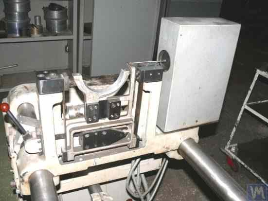
ਚਿੱਤਰ 2.1. ਬੈਲੇਂਸਿੰਗ ਮਸ਼ੀਨ ਮਾਡਲ DB-50 ਦਾ ਸਪੋਰਟ।
ਚਿੱਤਰ 2.1 ਵਿੱਚ ਦਿਖਾਏ ਅਨੁਸਾਰ, ਚੱਲਣਯੋਗ ਫਰੇਮ (ਸਲਾਈਡਰ) 2 ਨੂੰ ਪੱਟੀ ਸਪਰਿੰਗਾਂ 3 'ਤੇ ਸਸਪੈਂਸ਼ਨ ਦੀ ਵਰਤੋਂ ਕਰਕੇ ਸਪੋਰਟ ਦੇ ਸਥਿਰ ਖੰਭਿਆਂ 1 ਨਾਲ ਜੋੜਿਆ ਜਾਂਦਾ ਹੈ। ਸਪੋਰਟ 'ਤੇ ਲੱਗੇ ਰੋਟਰ ਦੇ ਅਸੰਤੁਲਨ ਕਾਰਨ ਪੈਦਾ ਹੋਈ ਸੈਂਟਰੀਫਿਊਗਲ ਫੋਰਸ ਦੇ ਪ੍ਰਭਾਵ ਹੇਠ, ਕੈਰੇਜ (ਸਲਾਈਡਰ) 2 ਸਥਿਰ ਖੰਭੇ 1 ਦੇ ਸਬੰਧ ਵਿੱਚ ਹਰੀਜ਼ੌਂਟਲ ਓਸਿਲੇਸ਼ਨ ਕਰ ਸਕਦਾ ਹੈ, ਜਿਸਨੂੰ ਇੱਕ ਵਾਈਬ੍ਰੇਸ਼ਨ ਸੈਂਸਰ ਦੀ ਵਰਤੋਂ ਕਰਕੇ ਮਾਪਿਆ ਜਾਂਦਾ ਹੈ।
ਇਸ ਸਪੋਰਟ ਦਾ ਢਾਂਚਾਗਤ ਨਿਰਮਾਣ ਕੈਰੇਜ ਓਸਿਲੇਸ਼ਨਾਂ ਦੀ ਘੱਟ ਕੁਦਰਤੀ ਬਾਰੰਬਾਰਤਾ ਪ੍ਰਾਪਤ ਕਰਨਾ ਯਕੀਨੀ ਬਣਾਉਂਦਾ ਹੈ, ਜੋ ਲਗਭਗ 1-2 Hz ਦੇ ਆਸਪਾਸ ਹੋ ਸਕਦੀ ਹੈ। ਇਹ 200 RPM ਤੋਂ ਸ਼ੁਰੂ ਹੋ ਕੇ, ਰੋਟਰ ਦੀਆਂ ਘੁੰਮਣ ਬਾਰੰਬਾਰਤਾਵਾਂ ਦੀ ਵਿਆਪਕ ਰੇਂਜ 'ਤੇ ਬੈਲੇਂਸਿੰਗ ਦੀ ਇਜਾਜ਼ਤ ਦਿੰਦਾ ਹੈ। ਇਹ ਵਿਸ਼ੇਸ਼ਤਾ, ਅਜਿਹੇ ਸਪੋਰਟਾਂ ਦੇ ਨਿਰਮਾਣ ਦੀ ਮੁਕਾਬਲਤਨ ਸਾਦਗੀ ਦੇ ਨਾਲ, ਇਸ ਡਿਜ਼ਾਈਨ ਨੂੰ ਸਾਡੇ ਬਹੁਤ ਸਾਰੇ ਖਪਤਕਾਰਾਂ ਲਈ ਆਕਰਸ਼ਕ ਬਣਾਉਂਦੀ ਹੈ ਜੋ ਵੱਖ-ਵੱਖ ਉਦੇਸ਼ਾਂ ਲਈ ਆਪਣੀਆਂ ਲੋੜਾਂ ਵਾਸਤੇ ਬੈਲੇਂਸਿੰਗ ਮਸ਼ੀਨਾਂ ਬਣਾਉਂਦੇ ਹਨ।
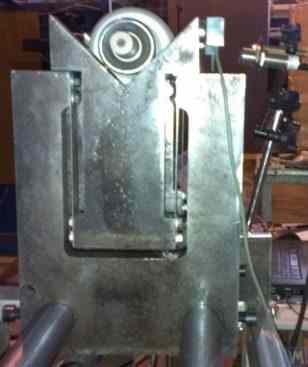
ਚਿੱਤਰ 2.2. "Polymer LTD", ਮਖਾਚਕਾਲਾ ਦੁਆਰਾ ਨਿਰਮਿਤ ਬੈਲੈਂਸਿੰਗ ਮਸ਼ੀਨ ਦਾ ਸਾਫ਼ਟ ਬੇਅਰਿੰਗ ਸਪੋਰਟ
ਚਿੱਤਰ 2.2 ਸਸਪੈਂਸ਼ਨ ਸਪ੍ਰਿੰਗਾਂ ਤੋਂ ਬਣੇ ਸਪੋਰਟਾਂ ਵਾਲੀ ਇੱਕ ਸਾਫ਼ਟ ਬੇਅਰਿੰਗ ਬੈਲੈਂਸਿੰਗ ਮਸ਼ੀਨ ਦੀ ਫੋਟੋ ਦਿਖਾਉਂਦਾ ਹੈ, ਜੋ "Polymer LTD" ਮਖਾਚਕਾਲਾ ਵਿਖੇ ਅੰਦਰੂਨੀ ਲੋੜਾਂ ਲਈ ਨਿਰਮਿਤ ਹੈ। ਇਹ ਮਸ਼ੀਨ ਪੌਲੀਮਰ ਸਮੱਗਰੀਆਂ ਦੇ ਉਤਪਾਦਨ ਵਿੱਚ ਵਰਤੇ ਜਾਂਦੇ ਰੋਲਰਾਂ ਨੂੰ ਬੈਲੈਂਸ ਕਰਨ ਲਈ ਤਿਆਰ ਕੀਤੀ ਗਈ ਹੈ।
ਚਿੱਤਰ 2.3 ਵਿੱਚ ਵਿਸ਼ੇਸ਼ ਟੂਲਾਂ ਦੀ ਬੈਲੇਂਸਿੰਗ ਲਈ ਬਣਾਈ ਗਈ ਇੱਕ ਬੈਲੇਂਸਿੰਗ ਮਸ਼ੀਨ ਦੀ ਫੋਟੋ ਹੈ, ਜਿਸ ਵਿੱਚ ਕੈਰੇਜ ਲਈ ਇਸੇ ਤਰ੍ਹਾਂ ਦੀ ਪੱਟੀ ਸਸਪੈਂਸ਼ਨ ਹੈ।
ਚਿੱਤਰ 2.4.a ਅਤੇ 2.4.b ਵਿੱਚ ਡਰਾਈਵ ਸ਼ਾਫਟਾਂ ਦੀ ਬੈਲੇਂਸਿੰਗ ਲਈ ਇੱਕ ਘਰੇਲੂ ਸਾਫਟ ਬੇਅਰਿੰਗ ਮਸ਼ੀਨ ਦੀਆਂ ਫੋਟੋਆਂ ਦਿਖਾਈਆਂ ਗਈਆਂ ਹਨ, ਜਿਸ ਦੇ ਸਪੋਰਟ ਵੀ ਪੱਟੀ ਸਸਪੈਂਸ਼ਨ ਸਪਰਿੰਗਾਂ ਦੀ ਵਰਤੋਂ ਕਰਕੇ ਬਣਾਏ ਗਏ ਹਨ।
ਚਿੱਤਰ 2.5 ਟਰਬੋਚਾਰਜਰਾਂ ਨੂੰ ਬੈਲੈਂਸ ਕਰਨ ਲਈ ਤਿਆਰ ਕੀਤੀ ਗਈ ਇੱਕ ਸਾਫ਼ਟ ਬੇਅਰਿੰਗ ਮਸ਼ੀਨ ਦੀ ਫੋਟੋ ਪੇਸ਼ ਕਰਦਾ ਹੈ, ਜਿਸ ਦੀਆਂ ਕੈਰੇਜਾਂ ਦੇ ਸਪੋਰਟ ਵੀ ਪੱਟੀ ਸਪ੍ਰਿੰਗਾਂ 'ਤੇ ਲਟਕਾਏ ਗਏ ਹਨ। ਇਹ ਮਸ਼ੀਨ, A. Shahgunyan (ਸੇਂਟ ਪੀਟਰਸਬਰਗ) ਦੀ ਨਿੱਜੀ ਵਰਤੋਂ ਲਈ ਬਣਾਈ ਗਈ, "Balanset 1" ਮਾਪਣ ਪ੍ਰਣਾਲੀ ਨਾਲ ਲੈਸ ਹੈ।
ਨਿਰਮਾਤਾ ਅਨੁਸਾਰ (ਚਿੱਤਰ 2.6 ਦੇਖੋ), ਇਹ ਮਸ਼ੀਨ 0.2 g*mm ਤੋਂ ਵੱਧ ਨਾ ਹੋਣ ਵਾਲੇ ਬਕਾਇਆ ਅਸੰਤੁਲਨ ਨਾਲ ਟਰਬਾਈਨਾਂ ਦੀ ਬੈਲੇਂਸਿੰਗ ਕਰਨ ਦੀ ਸਮਰੱਥਾ ਪ੍ਰਦਾਨ ਕਰਦੀ ਹੈ।
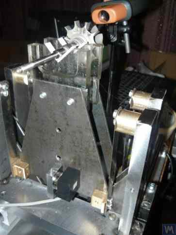
ਚਿੱਤਰ 2.3. ਪੱਟੀ ਸਪਰਿੰਗਾਂ 'ਤੇ ਸਪੋਰਟ ਸਸਪੈਂਸ਼ਨ ਵਾਲੀ ਟੂਲਾਂ ਦੀ ਬੈਲੇਂਸਿੰਗ ਲਈ ਸਾਫਟ ਬੇਅਰਿੰਗ ਮਸ਼ੀਨ
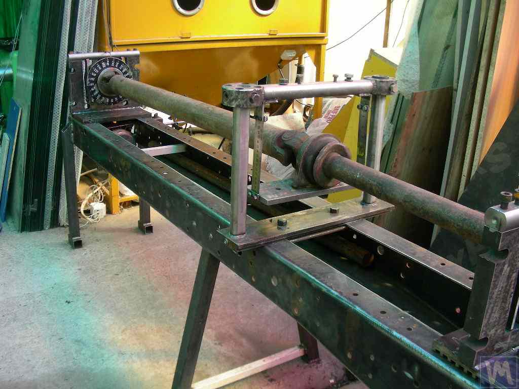
ਚਿੱਤਰ 2.4.a. ਡਰਾਈਵ ਸ਼ਾਫਟਾਂ ਦੀ ਬੈਲੇਂਸਿੰਗ ਲਈ ਸਾਫਟ ਬੇਅਰਿੰਗ ਮਸ਼ੀਨ (ਮਸ਼ੀਨ ਅਸੈਂਬਲਡ)
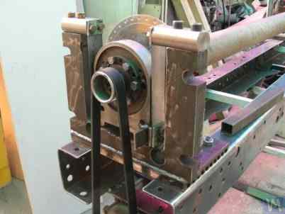
ਚਿੱਤਰ 2.4.b. ਪੱਟੀ ਸਪਰਿੰਗਾਂ 'ਤੇ ਲਟਕੇ ਕੈਰੇਜ ਸਪੋਰਟਾਂ ਵਾਲੀ ਡਰਾਈਵ ਸ਼ਾਫਟਾਂ ਦੀ ਬੈਲੇਂਸਿੰਗ ਲਈ ਸਾਫਟ ਬੇਅਰਿੰਗ ਮਸ਼ੀਨ। (ਸਪਰਿੰਗ ਪੱਟੀ ਸਸਪੈਂਸ਼ਨ ਵਾਲਾ ਲੀਡਿੰਗ ਸਪਿੰਡਲ ਸਪੋਰਟ)
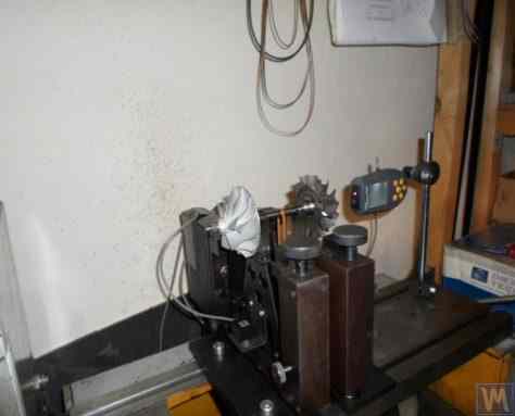
ਚਿੱਤਰ 2.5. ਸਟ੍ਰਿਪ ਸਪ੍ਰਿੰਗਾਂ ਵਾਲੇ ਸਪੋਰਟਾਂ ਸਮੇਤ ਟਰਬੋਚਾਰਜਰ ਸੰਤੁਲਨ ਲਈ ਸਾਫਟ ਬੇਅਰਿੰਗ ਮਸ਼ੀਨ, A. Shahgunyan (St. Petersburg) ਦੁਆਰਾ ਨਿਰਮਿਤ
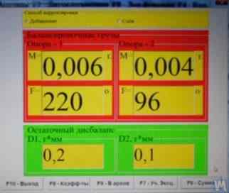
ਚਿੱਤਰ 2.6. A. Shahgunyan ਦੀ ਮਸ਼ੀਨ 'ਤੇ ਟਰਬਾਈਨ ਰੋਟਰ ਬੈਲੈਂਸਿੰਗ ਦੇ ਨਤੀਜੇ ਦਿਖਾਉਂਦੀ 'Balanset 1' ਮਾਪਣ ਪ੍ਰਣਾਲੀ ਦੀ ਸਕ੍ਰੀਨ ਕਾਪੀ
ਉੱਪਰ ਚਰਚਾ ਕੀਤੇ ਗਏ ਸਾਫਟ ਬੇਅਰਿੰਗ ਸੰਤੁਲਨ ਮਸ਼ੀਨ ਸਪੋਰਟਾਂ ਦੇ ਕਲਾਸਿਕ ਸੰਸਕਰਣ ਤੋਂ ਇਲਾਵਾ, ਹੋਰ ਸੰਰਚਨਾਤਮਕ ਹੱਲ ਵੀ ਵਿਆਪਕ ਤੌਰ 'ਤੇ ਵਰਤੇ ਜਾਣ ਲੱਗੇ ਹਨ।
ਚਿੱਤਰ 2.7 ਅਤੇ 2.8 ਡਰਾਈਵ ਸ਼ਾਫਟਾਂ ਲਈ ਬੈਲੈਂਸਿੰਗ ਮਸ਼ੀਨਾਂ ਦੀਆਂ ਫੋਟੋਆਂ ਪੇਸ਼ ਕਰਦਾ ਹੈ, ਜਿਨ੍ਹਾਂ ਦੇ ਸਪੋਰਟ ਫਲੈਟ (ਪਲੇਟ) ਸਪ੍ਰਿੰਗਾਂ ਦੇ ਆਧਾਰ 'ਤੇ ਬਣਾਏ ਗਏ ਹਨ। ਇਹ ਮਸ਼ੀਨਾਂ ਕ੍ਰਮਵਾਰ ਪ੍ਰਾਈਵੇਟ ਐਂਟਰਪ੍ਰਾਈਜ਼ "Dergacheva" ਅਤੇ LLC "Tatcardan" ("Kinetics-M") ਦੀਆਂ ਮਲਕੀਅਤੀ ਲੋੜਾਂ ਲਈ ਨਿਰਮਿਤ ਕੀਤੀਆਂ ਗਈਆਂ ਸਨ।
ਅਜਿਹੇ ਸਪੋਰਟਾਂ ਵਾਲੀਆਂ ਸਾਫ਼ਟ ਬੇਅਰਿੰਗ ਬੈਲੈਂਸਿੰਗ ਮਸ਼ੀਨਾਂ ਨੂੰ ਅਕਸਰ ਸ਼ੌਕੀਨ ਨਿਰਮਾਤਾਵਾਂ ਦੁਆਰਾ ਉਹਨਾਂ ਦੀ ਸਾਪੇਖਿਕ ਸਾਦਗੀ ਅਤੇ ਨਿਰਮਾਣ ਯੋਗਤਾ ਕਾਰਨ ਦੁਬਾਰਾ ਬਣਾਇਆ ਜਾਂਦਾ ਹੈ। ਇਹ ਪ੍ਰੋਟੋਟਾਈਪ ਆਮ ਤੌਰ 'ਤੇ ਜਾਂ ਤਾਂ "K. Schenck" ਦੀਆਂ VBRF ਸੀਰੀਜ਼ ਮਸ਼ੀਨਾਂ ਹੁੰਦੀਆਂ ਹਨ ਜਾਂ ਸਮਾਨ ਘਰੇਲੂ ਉਤਪਾਦਨ ਮਸ਼ੀਨਾਂ।
ਚਿੱਤਰ 2.7 ਅਤੇ 2.8 ਵਿੱਚ ਦਿਖਾਈਆਂ ਗਈਆਂ ਮਸ਼ੀਨਾਂ ਦੋ-ਸਪੋਰਟ, ਤਿੰਨ-ਸਪੋਰਟ, ਅਤੇ ਚਾਰ-ਸਪੋਰਟ ਡਰਾਈਵ ਸ਼ਾਫਟਾਂ ਦੇ ਸੰਤੁਲਨ ਲਈ ਤਿਆਰ ਕੀਤੀਆਂ ਗਈਆਂ ਹਨ। ਇਹਨਾਂ ਦੀ ਬਣਤਰ ਇੱਕੋ ਜਿਹੀ ਹੈ, ਜਿਸ ਵਿੱਚ ਸ਼ਾਮਲ ਹਨ:
- ਕਰਾਸ ਰਿਬਾਂ ਨਾਲ ਜੁੜੇ ਦੋ I-ਬੀਮਾਂ 'ਤੇ ਆਧਾਰਿਤ ਇੱਕ ਵੈਲਡਿਡ ਬੈਡਫ੍ਰੇਮ 1;
- ਇੱਕ ਸਥਿਰ (ਅੱਗੇ ਵਾਲਾ) ਸਪਿੰਡਲ ਸਪੋਰਟ 2;
- ਇੱਕ ਚੱਲਣਯੋਗ (ਪਿੱਛੇ ਵਾਲਾ) ਸਪਿੰਡਲ ਸਪੋਰਟ 3;
- ਇੱਕ ਜਾਂ ਦੋ ਚੱਲਣਯੋਗ (ਵਿਚਕਾਰਲੇ) ਸਪੋਰਟ 4। ਸਪੋਰਟ 2 ਅਤੇ 3 ਵਿੱਚ ਸਪਿੰਡਲ ਯੂਨਿਟ 5 ਅਤੇ 6 ਮੌਜੂਦ ਹਨ, ਜੋ ਸੰਤੁਲਿਤ ਕੀਤੇ ਜਾਣ ਵਾਲੇ ਡਰਾਈਵ ਸ਼ਾਫਟ 7 ਨੂੰ ਮਸ਼ੀਨ 'ਤੇ ਲਗਾਉਣ ਲਈ ਹਨ।
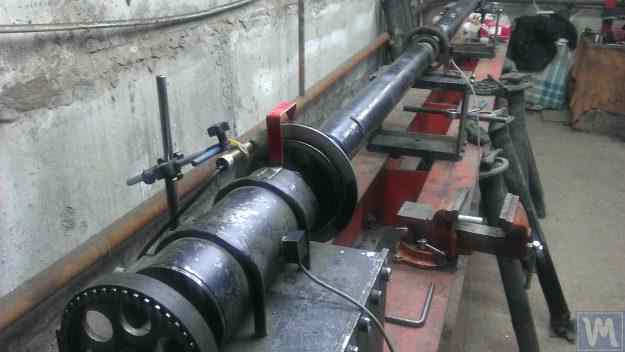
ਚਿੱਤਰ 2.7. ਫਲੈਟ (ਪਲੇਟ) ਸਪ੍ਰਿੰਗਾਂ 'ਤੇ ਸਪੋਰਟਾਂ ਵਾਲੀ, ਪ੍ਰਾਈਵੇਟ ਐਂਟਰਪ੍ਰਾਈਜ਼ "Dergacheva" ਦੀ ਡਰਾਈਵ ਸ਼ਾਫਟ ਬੈਲੈਂਸਿੰਗ ਲਈ ਸਾਫ਼ਟ ਬੇਅਰਿੰਗ ਮਸ਼ੀਨ
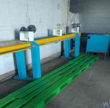
ਚਿੱਤਰ 2.8. ਫਲੈਟ ਸਪ੍ਰਿੰਗਾਂ 'ਤੇ ਸਪੋਰਟਾਂ ਵਾਲੀ, LLC "Tatcardan" ("Kinetics-M") ਦੀ ਡਰਾਈਵ ਸ਼ਾਫਟ ਬੈਲੈਂਸਿੰਗ ਲਈ ਸਾਫ਼ਟ ਬੇਅਰਿੰਗ ਮਸ਼ੀਨ
ਸਾਰੇ ਸਪੋਰਟਾਂ 'ਤੇ ਵਾਈਬ੍ਰੇਸ਼ਨ ਸੈਂਸਰ 8 ਲਗਾਏ ਗਏ ਹਨ, ਜੋ ਸਪੋਰਟਾਂ ਦੇ ਖਿਤਿਜੀ (transverse) ਦੋਲਨਾਂ ਨੂੰ ਮਾਪਣ ਲਈ ਵਰਤੇ ਜਾਂਦੇ ਹਨ। ਸਪੋਰਟ 2 'ਤੇ ਲਗਾਇਆ ਗਿਆ ਲੀਡਿੰਗ ਸਪਿੰਡਲ 5, ਇੱਕ ਬੈਲਟ ਡਰਾਈਵ ਰਾਹੀਂ ਇਲੈਕਟ੍ਰਿਕ ਮੋਟਰ ਦੁਆਰਾ ਘੁੰਮਾਇਆ ਜਾਂਦਾ ਹੈ।
ਚਿੱਤਰ 2.9.a ਅਤੇ 2.9.b ਸੰਤੁਲਨ ਮਸ਼ੀਨ ਦੇ ਸਪੋਰਟ ਦੀਆਂ ਫੋਟੋਆਂ ਦਿਖਾਉਂਦੇ ਹਨ, ਜੋ ਫਲੈਟ ਸਪ੍ਰਿੰਗਾਂ 'ਤੇ ਆਧਾਰਿਤ ਹੈ।
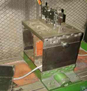
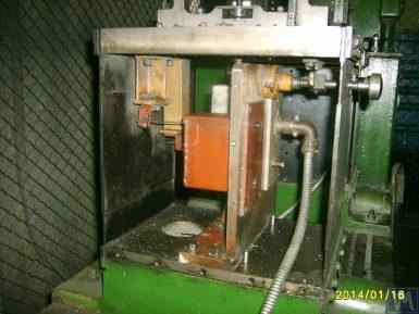
ਚਿੱਤਰ 2.9. ਫਲੈਟ ਸਪ੍ਰਿੰਗਾਂ ਵਾਲਾ ਸਾਫਟ ਬੇਅਰਿੰਗ ਸੰਤੁਲਨ ਮਸ਼ੀਨ ਸਪੋਰਟ
- a) ਸਾਈਡ ਵਿਊ;
- b) ਫਰੰਟ ਵਿਊ
ਕਿਉਂਕਿ ਸ਼ੌਕੀਨ ਨਿਰਮਾਤਾ ਅਕਸਰ ਆਪਣੀਆਂ ਡਿਜ਼ਾਈਨਾਂ ਵਿੱਚ ਅਜਿਹੇ ਸਪੋਰਟ ਵਰਤਦੇ ਹਨ, ਇਸ ਲਈ ਇਹਨਾਂ ਦੀ ਬਣਤਰ ਦੀਆਂ ਵਿਸ਼ੇਸ਼ਤਾਵਾਂ ਨੂੰ ਹੋਰ ਵਿਸਥਾਰ ਵਿੱਚ ਦੇਖਣਾ ਲਾਭਦਾਇਕ ਹੈ। ਜਿਵੇਂ ਚਿੱਤਰ 2.9.a ਵਿੱਚ ਦਿਖਾਇਆ ਗਿਆ ਹੈ, ਇਸ ਸਪੋਰਟ ਵਿੱਚ ਤਿੰਨ ਮੁੱਖ ਹਿੱਸੇ ਹਨ:
- ਹੇਠਲੀ ਸਪੋਰਟ ਪਲੇਟ 1: ਅੱਗੇ ਵਾਲੇ ਸਪਿੰਡਲ ਸਪੋਰਟ ਲਈ, ਪਲੇਟ ਗਾਈਡਾਂ ਨਾਲ ਸਖ਼ਤੀ ਨਾਲ ਜੁੜੀ ਹੁੰਦੀ ਹੈ; ਵਿਚਕਾਰਲੇ ਸਪੋਰਟਾਂ ਜਾਂ ਪਿੱਛੇ ਵਾਲੇ ਸਪਿੰਡਲ ਸਪੋਰਟਾਂ ਲਈ, ਹੇਠਲੀ ਪਲੇਟ ਇੱਕ ਕੈਰਿਜ ਵਜੋਂ ਡਿਜ਼ਾਈਨ ਕੀਤੀ ਜਾਂਦੀ ਹੈ ਜੋ ਫਰੇਮ ਦੀਆਂ ਗਾਈਡਾਂ ਦੇ ਨਾਲ-ਨਾਲ ਚੱਲ ਸਕਦੀ ਹੈ।
- ਉੱਪਰਲੀ ਸਪੋਰਟ ਪਲੇਟ 2, ਜਿਸ 'ਤੇ ਸਪੋਰਟ ਯੂਨਿਟ ਲਗਾਏ ਜਾਂਦੇ ਹਨ (ਰੋਲਰ ਸਪੋਰਟ 4, ਸਪਿੰਡਲ, ਵਿਚਕਾਰਲੇ ਬੇਅਰਿੰਗ, ਆਦਿ)।
- ਦੋ ਫਲੈਟ ਸਪ੍ਰਿੰਗ 3, ਜੋ ਹੇਠਲੀ ਅਤੇ ਉੱਪਰਲੀ ਬੇਅਰਿੰਗ ਪਲੇਟਾਂ ਨੂੰ ਜੋੜਦੇ ਹਨ।
ਸਪੋਰਟਾਂ ਵਿੱਚ ਸੰਚਾਲਨ ਦੌਰਾਨ ਵਧੀ ਹੋਈ ਵਾਈਬ੍ਰੇਸ਼ਨ ਦੇ ਜੋਖਮ ਨੂੰ ਰੋਕਣ ਲਈ, ਜੋ ਸੰਤੁਲਿਤ ਕੀਤੇ ਜਾਣ ਵਾਲੇ ਰੋਟਰ ਦੇ ਪ੍ਰਵੇਗ ਜਾਂ ਮੰਦੀ ਦੌਰਾਨ ਹੋ ਸਕਦਾ ਹੈ, ਸਪੋਰਟਾਂ ਵਿੱਚ ਇੱਕ ਲਾਕਿੰਗ ਵਿਧੀ ਸ਼ਾਮਲ ਹੋ ਸਕਦੀ ਹੈ (ਦੇਖੋ ਚਿੱਤਰ 2.9.b)। ਇਸ ਵਿਧੀ ਵਿੱਚ ਇੱਕ ਸਖ਼ਤ ਬਰੈਕਟ 5 ਸ਼ਾਮਲ ਹੈ, ਜਿਸਨੂੰ ਇੱਕ ਐਕਸੈਂਟ੍ਰਿਕ ਲਾਕ 6 ਦੁਆਰਾ ਸ਼ਾਮਲ ਕੀਤਾ ਜਾ ਸਕਦਾ ਹੈ ਜੋ ਸਪੋਰਟ ਦੇ ਇੱਕ ਫਲੈਟ ਸਪ੍ਰਿੰਗ ਨਾਲ ਜੁੜਿਆ ਹੁੰਦਾ ਹੈ। ਜਦੋਂ ਲਾਕ 6 ਅਤੇ ਬਰੈਕਟ 5 ਸ਼ਾਮਲ ਹੁੰਦੇ ਹਨ, ਤਾਂ ਸਪੋਰਟ ਲਾਕ ਹੋ ਜਾਂਦਾ ਹੈ, ਜਿਸ ਨਾਲ ਪ੍ਰਵੇਗ ਅਤੇ ਮੰਦੀ ਦੌਰਾਨ ਵਧੀ ਹੋਈ ਵਾਈਬ੍ਰੇਸ਼ਨ ਦਾ ਜੋਖਮ ਖਤਮ ਹੋ ਜਾਂਦਾ ਹੈ।
ਫਲੈਟ (ਪਲੇਟ) ਸਪ੍ਰਿੰਗਾਂ ਨਾਲ ਬਣੇ ਸਪੋਰਟਾਂ ਨੂੰ ਡਿਜ਼ਾਈਨ ਕਰਦੇ ਸਮੇਂ, ਮਸ਼ੀਨ ਨਿਰਮਾਤਾ ਨੂੰ ਇਹਨਾਂ ਦੇ ਕੁਦਰਤੀ ਦੋਲਨਾਂ ਦੀ ਬਾਰੰਬਾਰਤਾ ਦਾ ਮੁਲਾਂਕਣ ਕਰਨਾ ਚਾਹੀਦਾ ਹੈ, ਜੋ ਸਪ੍ਰਿੰਗਾਂ ਦੀ ਸਖ਼ਤੀ ਅਤੇ ਸੰਤੁਲਿਤ ਕੀਤੇ ਜਾਣ ਵਾਲੇ ਰੋਟਰ ਦੇ ਪੁੰਜ 'ਤੇ ਨਿਰਭਰ ਕਰਦੀ ਹੈ। ਇਸ ਪੈਰਾਮੀਟਰ ਨੂੰ ਜਾਣ ਕੇ ਡਿਜ਼ਾਈਨਰ ਸੰਤੁਲਨ ਦੌਰਾਨ ਸਪੋਰਟਾਂ ਦੇ ਰੈਜ਼ੋਨੈਂਟ ਦੋਲਨਾਂ ਦੇ ਖ਼ਤਰੇ ਤੋਂ ਬਚਦੇ ਹੋਏ, ਰੋਟਰ ਦੀਆਂ ਸੰਚਾਲਨ ਘੁੰਮਣ ਬਾਰੰਬਾਰਤਾਵਾਂ ਦੀ ਸੀਮਾ ਨੂੰ ਸੋਚ-ਸਮਝ ਕੇ ਚੁਣ ਸਕਦਾ ਹੈ।
ਸਪੋਰਟਾਂ ਅਤੇ ਸੰਤੁਲਨ ਮਸ਼ੀਨਾਂ ਦੇ ਹੋਰ ਹਿੱਸਿਆਂ ਦੇ ਦੋਲਨਾਂ ਦੀ ਕੁਦਰਤੀ ਬਾਰੰਬਾਰਤਾ ਦੀ ਗਣਨਾ ਅਤੇ ਪ੍ਰਯੋਗਾਤਮਕ ਤੌਰ 'ਤੇ ਨਿਰਧਾਰਨ ਕਰਨ ਲਈ ਸਿਫਾਰਸ਼ਾਂ, ਸੈਕਸ਼ਨ 3 ਵਿੱਚ ਚਰਚਾ ਕੀਤੀਆਂ ਗਈਆਂ ਹਨ।
ਜਿਵੇਂ ਪਹਿਲਾਂ ਦੱਸਿਆ ਗਿਆ ਹੈ, ਫਲੈਟ (ਪਲੇਟ) ਸਪ੍ਰਿੰਗਾਂ ਦੀ ਵਰਤੋਂ ਕਰਕੇ ਬਣੇ ਸਪੋਰਟ ਡਿਜ਼ਾਈਨ ਦੀ ਸਾਦਗੀ ਅਤੇ ਬਣਾਉਣਯੋਗਤਾ, ਵੱਖ-ਵੱਖ ਉਦੇਸ਼ਾਂ ਲਈ ਸੰਤੁਲਨ ਮਸ਼ੀਨਾਂ ਦੇ ਸ਼ੌਕੀਨ ਨਿਰਮਾਤਾਵਾਂ ਨੂੰ ਆਕਰਸ਼ਿਤ ਕਰਦੀ ਹੈ, ਜਿਸ ਵਿੱਚ ਕ੍ਰੈਂਕਸ਼ਾਫਟ, ਆਟੋਮੋਟਿਵ ਟਰਬੋਚਾਰਜਰ ਰੋਟਰ ਆਦਿ ਸੰਤੁਲਿਤ ਕਰਨ ਵਾਲੀਆਂ ਮਸ਼ੀਨਾਂ ਸ਼ਾਮਲ ਹਨ।
ਇੱਕ ਉਦਾਹਰਨ ਦੇ ਤੌਰ 'ਤੇ, ਚਿੱਤਰ 2.10.a ਅਤੇ 2.10.b ਟਰਬੋਚਾਰਜਰ ਰੋਟਰਾਂ ਨੂੰ ਬੈਲੈਂਸ ਕਰਨ ਲਈ ਤਿਆਰ ਕੀਤੀ ਗਈ ਮਸ਼ੀਨ ਦਾ ਇੱਕ ਆਮ ਸਕੈਚ ਪੇਸ਼ ਕਰਦੇ ਹਨ। ਇਹ ਮਸ਼ੀਨ LLC "SuraTurbo" ਪੇਂਜ਼ਾ ਵਿਖੇ ਅੰਦਰੂਨੀ ਲੋੜਾਂ ਲਈ ਨਿਰਮਿਤ ਕੀਤੀ ਗਈ ਹੈ ਅਤੇ ਵਰਤੀ ਜਾਂਦੀ ਹੈ।
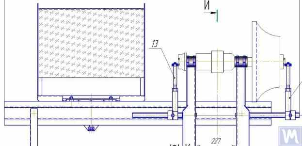
2.10.a. ਟਰਬੋਚਾਰਜਰ ਰੋਟਰ ਸੰਤੁਲਨ ਲਈ ਮਸ਼ੀਨ (ਸਾਈਡ ਵਿਊ)
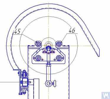
2.10.b. ਟਰਬੋਚਾਰਜਰ ਰੋਟਰ ਸੰਤੁਲਨ ਲਈ ਮਸ਼ੀਨ (ਅੱਗੇ ਵਾਲੇ ਸਪੋਰਟ ਵਾਲੇ ਪਾਸੇ ਤੋਂ ਵਿਊ)
ਪਹਿਲਾਂ ਚਰਚਾ ਕੀਤੀਆਂ ਗਈਆਂ ਸਾਫਟ ਬੇਅਰਿੰਗ ਸੰਤੁਲਨ ਮਸ਼ੀਨਾਂ ਤੋਂ ਇਲਾਵਾ, ਕਈ ਵਾਰ ਮੁਕਾਬਲਤਨ ਸਧਾਰਨ ਸਾਫਟ ਬੇਅਰਿੰਗ ਸਟੈਂਡ ਵੀ ਬਣਾਏ ਜਾਂਦੇ ਹਨ। ਇਹ ਸਟੈਂਡ ਘੱਟੋ-ਘੱਟ ਲਾਗਤ ਨਾਲ ਵੱਖ-ਵੱਖ ਉਦੇਸ਼ਾਂ ਲਈ ਘੁੰਮਣ ਵਾਲੇ ਯੰਤਰਾਂ ਦੇ ਉੱਚ-ਗੁਣਵੱਤਾ ਸੰਤੁਲਨ ਦੀ ਆਗਿਆ ਦਿੰਦੇ ਹਨ।
ਹੇਠਾਂ ਅਜਿਹੇ ਕਈ ਸਟੈਂਡਾਂ ਦੀ ਸਮੀਖਿਆ ਕੀਤੀ ਗਈ ਹੈ, ਜੋ ਸਿਲੰਡਰਿਕ ਕੰਪ੍ਰੈਸ਼ਨ ਸਪ੍ਰਿੰਗਾਂ 'ਤੇ ਰੱਖੇ ਗਏ ਇੱਕ ਫਲੈਟ ਪਲੇਟ (ਜਾਂ ਫਰੇਮ) ਦੇ ਆਧਾਰ 'ਤੇ ਬਣਾਏ ਗਏ ਹਨ। ਇਹ ਸਪ੍ਰਿੰਗਾਂ ਆਮ ਤੌਰ 'ਤੇ ਇਸ ਤਰ੍ਹਾਂ ਚੁਣੀਆਂ ਜਾਂਦੀਆਂ ਹਨ ਕਿ ਪਲੇਟ 'ਤੇ ਲਗਾਈ ਗਈ ਬੈਲੈਂਸ ਕੀਤੀ ਜਾਣ ਵਾਲੀ ਵਿਧੀ ਸਮੇਤ ਪਲੇਟ ਦੇ ਓਸੀਲੇਸ਼ਨ ਦੀ ਕੁਦਰਤੀ ਬਾਰੰਬਾਰਤਾ, ਬੈਲੈਂਸਿੰਗ ਦੌਰਾਨ ਇਸ ਵਿਧੀ ਦੇ ਰੋਟਰ ਦੀ ਘੁੰਮਣ ਬਾਰੰਬਾਰਤਾ ਨਾਲੋਂ 2 ਤੋਂ 3 ਗੁਣਾ ਘੱਟ ਹੋਵੇ।
ਚਿੱਤਰ 2.11 P. Asharin ਦੁਆਰਾ ਘਰੇਲੂ ਉਤਪਾਦਨ ਲਈ ਨਿਰਮਿਤ, ਅਬ੍ਰੇਸਿਵ ਵ੍ਹੀਲਾਂ ਦੇ ਸੰਤੁਲਨ ਲਈ ਇੱਕ ਸਟੈਂਡ ਦੀ ਫੋਟੋ ਦਿਖਾਉਂਦਾ ਹੈ।
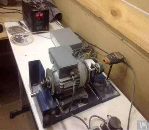
ਚਿੱਤਰ 2.11. ਅਬ੍ਰੇਸਿਵ ਵ੍ਹੀਲਾਂ ਦੇ ਸੰਤੁਲਨ ਲਈ ਸਟੈਂਡ
ਸਟੈਂਡ ਵਿੱਚ ਹੇਠ ਲਿਖੇ ਮੁੱਖ ਹਿੱਸੇ ਸ਼ਾਮਲ ਹਨ:
- ਪਲੇਟ 1, ਜੋ ਚਾਰ ਸਿਲੰਡਰਿਕ ਸਪ੍ਰਿੰਗਾਂ 2 'ਤੇ ਲਗਾਈ ਗਈ ਹੈ;
- ਇਲੈਕਟ੍ਰਿਕ ਮੋਟਰ 3, ਜਿਸਦਾ ਰੋਟਰ ਸਪਿੰਡਲ ਵਜੋਂ ਵੀ ਕੰਮ ਕਰਦਾ ਹੈ, ਜਿਸ 'ਤੇ ਇੱਕ ਮੈਂਡਰਲ 4 ਲਗਾਈ ਗਈ ਹੈ, ਜੋ ਅਬ੍ਰੇਸਿਵ ਵ੍ਹੀਲ ਨੂੰ ਸਪਿੰਡਲ 'ਤੇ ਲਗਾਉਣ ਅਤੇ ਸੁਰੱਖਿਅਤ ਕਰਨ ਲਈ ਵਰਤੀ ਜਾਂਦੀ ਹੈ।
ਇਸ ਸਟੈਂਡ ਦੀ ਇੱਕ ਮੁੱਖ ਵਿਸ਼ੇਸ਼ਤਾ ਇਲੈਕਟ੍ਰਿਕ ਮੋਟਰ ਦੇ ਰੋਟਰ ਦੇ ਘੁੰਮਣ ਕੋਣ ਲਈ ਇੱਕ ਪਲਸ ਸੈਂਸਰ 5 ਦਾ ਸ਼ਾਮਲ ਹੋਣਾ ਹੈ, ਜੋ ਸਟੈਂਡ ("Balanset 2C") ਦੀ ਮਾਪਣ ਪ੍ਰਣਾਲੀ ਦੇ ਹਿੱਸੇ ਵਜੋਂ ਅਬਰੇਸਿਵ ਵ੍ਹੀਲ ਤੋਂ ਸੁਧਾਰਕ ਪੁੰਜ ਹਟਾਉਣ ਲਈ ਕੋਣੀ ਸਥਿਤੀ ਨਿਰਧਾਰਤ ਕਰਨ ਵਾਸਤੇ ਵਰਤਿਆ ਜਾਂਦਾ ਹੈ।
ਚਿੱਤਰ 2.12 ਵੈਕਿਊਮ ਪੰਪਾਂ ਨੂੰ ਬੈਲੈਂਸ ਕਰਨ ਲਈ ਵਰਤੇ ਜਾਂਦੇ ਇੱਕ ਸਟੈਂਡ ਦੀ ਫੋਟੋ ਦਿਖਾਉਂਦਾ ਹੈ। ਇਹ ਸਟੈਂਡ JSC "Measurement Plant" ਦੇ ਆਦੇਸ਼ ਅਨੁਸਾਰ ਵਿਕਸਿਤ ਕੀਤਾ ਗਿਆ ਸੀ।
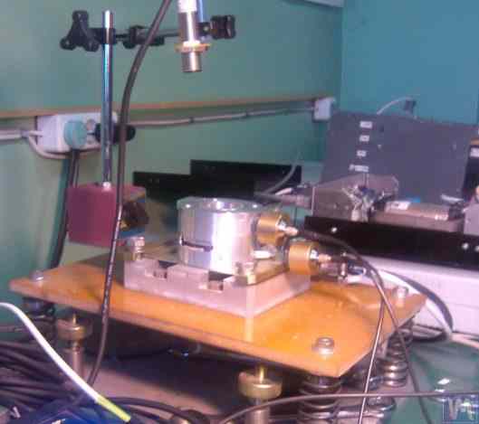
ਚਿੱਤਰ 2.12. JSC "Measurement Plant" ਦਾ ਵੈਕਿਊਮ ਪੰਪ ਬੈਲੈਂਸਿੰਗ ਸਟੈਂਡ
ਇਸ ਸਟੈਂਡ ਦੇ ਆਧਾਰ ਵਿੱਚ ਵੀ ਵਰਤਿਆ ਗਿਆ ਹੈ ਪਲੇਟ 1, ਜੋ ਸਿਲੰਡਰਿਕ ਸਪ੍ਰਿੰਗਾਂ 2 'ਤੇ ਲਗਾਈ ਗਈ ਹੈ। ਪਲੇਟ 1 'ਤੇ, ਇੱਕ ਵੈਕਿਊਮ ਪੰਪ 3 ਲਗਾਇਆ ਗਿਆ ਹੈ, ਜਿਸਦੀ ਆਪਣੀ ਇਲੈਕਟ੍ਰਿਕ ਡਰਾਈਵ ਹੈ ਜੋ 0 ਤੋਂ 60,000 RPM ਤੱਕ ਵਿਆਪਕ ਤੌਰ 'ਤੇ ਸਪੀਡ ਬਦਲ ਸਕਦੀ ਹੈ। ਵਾਈਬ੍ਰੇਸ਼ਨ ਸੈਂਸਰ 4 ਪੰਪ ਕੈਸਿੰਗ 'ਤੇ ਲਗਾਏ ਗਏ ਹਨ, ਜੋ ਵੱਖ-ਵੱਖ ਉਚਾਈਆਂ 'ਤੇ ਦੋ ਵੱਖ-ਵੱਖ ਸੈਕਸ਼ਨਾਂ ਵਿੱਚ ਵਾਈਬ੍ਰੇਸ਼ਨ ਮਾਪਣ ਲਈ ਵਰਤੇ ਜਾਂਦੇ ਹਨ।
ਪੰਪ ਰੋਟਰ ਦੇ ਘੁੰਮਣ ਕੋਣ ਨਾਲ ਵਾਈਬ੍ਰੇਸ਼ਨ ਮਾਪ ਪ੍ਰਕਿਰਿਆ ਦੇ ਸਮਕਾਲੀਕਰਨ ਲਈ, ਸਟੈਂਡ 'ਤੇ ਇੱਕ ਲੇਜ਼ਰ ਫੇਜ਼ ਐਂਗਲ ਸੈਂਸਰ 5 ਵਰਤਿਆ ਜਾਂਦਾ ਹੈ। ਅਜਿਹੇ ਸਟੈਂਡਾਂ ਦੀ ਦਿੱਖ ਵਿੱਚ ਸਧਾਰਨ ਬਾਹਰੀ ਬਣਤਰ ਦੇ ਬਾਵਜੂਦ, ਇਹ ਪੰਪ ਦੇ ਇੰਪੈਲਰ ਦੀ ਬਹੁਤ ਉੱਚ-ਗੁਣਵੱਤਾ ਵਾਲੀ ਬੈਲੈਂਸਿੰਗ ਪ੍ਰਾਪਤ ਕਰਨ ਦੀ ਇਜਾਜ਼ਤ ਦਿੰਦਾ ਹੈ।
ਉਦਾਹਰਨ ਲਈ, ਸਬ-ਕ੍ਰਿਟੀਕਲ ਰੋਟੇਸ਼ਨਲ ਫ੍ਰੀਕੁਐਂਸੀ 'ਤੇ, ਪੰਪ ਰੋਟਰ ਦਾ ਬਾਕੀ ਬਚਿਆ ਅਸੰਤੁਲਨ ISO 21940-11 (ਪਹਿਲਾਂ ISO 1940-1) ਵਿੱਚ ਪਰਿਭਾਸ਼ਿਤ ਸਭ ਤੋਂ ਬਾਰੀਕ ਬੈਲੇਂਸ ਗੁਣਵੱਤਾ ਗ੍ਰੇਡ, G0.4, ਦੀ ਸਹਿਣਸ਼ੀਲਤਾ ਤੋਂ ਹੇਠਾਂ ਹੈ — ਇੱਕ ਇਨ-ਹਾਊਸ ਬੈਂਚ ਨਤੀਜਾ ਜੋ ਇੱਕ ਨੋਸ਼ਨਲ G0.16 ਦੇ ਬਰਾਬਰ ਹੈ, ਜੋ ਮਿਆਰ ਵਿੱਚ ਸੂਚੀਬੱਧ ਕਿਸੇ ਵੀ ਗ੍ਰੇਡ ਨਾਲੋਂ ਸਖ਼ਤ ਹੈ।
8,000 RPM ਤੱਕ ਦੀ ਘੁੰਮਣ ਸਪੀਡ 'ਤੇ ਸੰਤੁਲਨ ਦੌਰਾਨ ਪ੍ਰਾਪਤ ਕੀਤੀ ਪੰਪ ਕੈਸਿੰਗ ਦੀ ਬਾਕੀ ਰਹਿੰਦੀ ਵਾਈਬ੍ਰੇਸ਼ਨ 0.01 mm/sec ਤੋਂ ਵੱਧ ਨਹੀਂ ਹੁੰਦੀ।
ਉੱਪਰ ਦੱਸੀ ਗਈ ਯੋਜਨਾ ਅਨੁਸਾਰ ਨਿਰਮਿਤ ਸੰਤੁਲਨ ਸਟੈਂਡ ਹੋਰ ਯੰਤਰਾਂ, ਜਿਵੇਂ ਕਿ ਪੱਖਿਆਂ (fans), ਦੇ ਸੰਤੁਲਨ ਵਿੱਚ ਵੀ ਪ੍ਰਭਾਵਸ਼ਾਲੀ ਹਨ। ਪੱਖਿਆਂ ਦੇ ਸੰਤੁਲਨ ਲਈ ਤਿਆਰ ਕੀਤੇ ਗਏ ਸਟੈਂਡਾਂ ਦੀਆਂ ਉਦਾਹਰਣਾਂ ਚਿੱਤਰ 2.13 ਅਤੇ 2.14 ਵਿੱਚ ਦਿਖਾਈਆਂ ਗਈਆਂ ਹਨ।
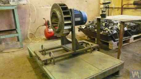
ਚਿੱਤਰ 2.13. ਪੱਖਾ ਇੰਪੈਲਰਾਂ ਦੇ ਸੰਤੁਲਨ ਲਈ ਸਟੈਂਡ
ਅਜਿਹੇ ਸਟੈਂਡਾਂ 'ਤੇ ਪ੍ਰਾਪਤ ਹੋਈ ਪੱਖੇ ਦੀ ਬੈਲੈਂਸਿੰਗ ਦੀ ਗੁਣਵੱਤਾ ਕਾਫ਼ੀ ਉੱਚੀ ਹੈ। "Atlant-project" LLC ਦੇ ਮਾਹਿਰਾਂ ਦੇ ਅਨੁਸਾਰ, "Kinematics" LLC ਦੀਆਂ ਸਿਫ਼ਾਰਸ਼ਾਂ ਦੇ ਆਧਾਰ 'ਤੇ ਉਹਨਾਂ ਦੁਆਰਾ ਡਿਜ਼ਾਈਨ ਕੀਤੇ ਸਟੈਂਡ (ਵੇਖੋ ਚਿੱਤਰ 2.14) 'ਤੇ, ਪੱਖਿਆਂ ਨੂੰ ਬੈਲੈਂਸ ਕਰਨ ਸਮੇਂ ਪ੍ਰਾਪਤ ਬਕਾਇਆ ਵਾਈਬ੍ਰੇਸ਼ਨ ਦਾ ਪੱਧਰ 0.8 mm/sec ਸੀ। ਇਹ ISO 31350-2007 "ਵਾਈਬ੍ਰੇਸ਼ਨ। ਉਦਯੋਗਿਕ ਪੱਖੇ। ਪੈਦਾ ਹੋਈ ਵਾਈਬ੍ਰੇਸ਼ਨ ਅਤੇ ਬੈਲੈਂਸ ਗੁਣਵੱਤਾ ਲਈ ਲੋੜਾਂ।" ਦੇ ਅਨੁਸਾਰ BV5 ਸ਼੍ਰੇਣੀ ਦੇ ਪੱਖਿਆਂ ਲਈ ਨਿਰਧਾਰਿਤ ਸਹਿਣਸ਼ੀਲਤਾ ਨਾਲੋਂ ਤਿੰਨ ਗੁਣਾ ਤੋਂ ਵੱਧ ਬਿਹਤਰ ਹੈ।
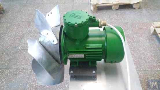
ਚਿੱਤਰ 2.14. "Atlant-project" LLC, ਪੋਡੋਲਸਕ ਦੁਆਰਾ ਵਿਸਫੋਟ-ਰੋਧਕ ਉਪਕਰਣਾਂ ਦੇ ਪੱਖੇ ਦੇ ਇੰਪੈਲਰਾਂ ਨੂੰ ਬੈਲੈਂਸ ਕਰਨ ਲਈ ਸਟੈਂਡ
JSC "Lissant Fan Factory" ਵਿਖੇ ਪ੍ਰਾਪਤ ਸਮਾਨ ਅੰਕੜੇ ਦਿਖਾਉਂਦੇ ਹਨ ਕਿ ਡਕਟ ਪੱਖਿਆਂ ਦੇ ਸੀਰੀਏਲ ਉਤਪਾਦਨ ਵਿੱਚ ਵਰਤੇ ਜਾਂਦੇ ਅਜਿਹੇ ਸਟੈਂਡਾਂ ਨੇ ਲਗਾਤਾਰ 0.1 mm/s ਤੋਂ ਵੱਧ ਨਾ ਹੋਣ ਵਾਲੀ ਬਕਾਇਆ ਵਾਈਬ੍ਰੇਸ਼ਨ ਯਕੀਨੀ ਬਣਾਈ।
2.2. ਹਾਰਡ ਬੇਅਰਿੰਗ ਮਸ਼ੀਨਾਂ
ਹਾਰਡ ਬੇਅਰਿੰਗ ਸੰਤੁਲਨ ਮਸ਼ੀਨਾਂ, ਪਹਿਲਾਂ ਚਰਚਾ ਕੀਤੀਆਂ ਗਈਆਂ ਸਾਫਟ ਬੇਅਰਿੰਗ ਮਸ਼ੀਨਾਂ ਤੋਂ, ਆਪਣੇ ਸਪੋਰਟਾਂ ਦੇ ਡਿਜ਼ਾਈਨ ਵਿੱਚ ਵੱਖਰੀਆਂ ਹਨ। ਇਹਨਾਂ ਦੇ ਸਪੋਰਟ ਗੁੰਝਲਦਾਰ ਸਲਾਟਾਂ (ਕੱਟ-ਆਊਟ) ਵਾਲੀਆਂ ਸਖ਼ਤ ਪਲੇਟਾਂ ਦੇ ਰੂਪ ਵਿੱਚ ਬਣਾਏ ਜਾਂਦੇ ਹਨ। ਇਹਨਾਂ ਸਪੋਰਟਾਂ ਦੀਆਂ ਕੁਦਰਤੀ ਬਾਰੰਬਾਰਤਾਵਾਂ, ਮਸ਼ੀਨ 'ਤੇ ਸੰਤੁਲਿਤ ਕੀਤੇ ਜਾਣ ਵਾਲੇ ਰੋਟਰ ਦੀ ਵੱਧ ਤੋਂ ਵੱਧ ਘੁੰਮਣ ਬਾਰੰਬਾਰਤਾ ਤੋਂ ਕਾਫ਼ੀ (ਘੱਟੋ-ਘੱਟ 2-3 ਗੁਣਾ) ਵੱਧ ਹੁੰਦੀਆਂ ਹਨ।
ਹਾਰਡ ਬੇਅਰਿੰਗ ਮਸ਼ੀਨਾਂ ਸਾਫਟ ਬੇਅਰਿੰਗ ਮਸ਼ੀਨਾਂ ਨਾਲੋਂ ਵਧੇਰੇ ਬਹੁਮੁਖੀ ਹਨ, ਕਿਉਂਕਿ ਇਹ ਆਮ ਤੌਰ 'ਤੇ ਪੁੰਜ ਅਤੇ ਆਕਾਰਕ ਵਿਸ਼ੇਸ਼ਤਾਵਾਂ ਦੀ ਵਿਸ਼ਾਲ ਸੀਮਾ ਉੱਤੇ ਰੋਟਰਾਂ ਦੇ ਉੱਚ-ਗੁਣਵੱਤਾ ਸੰਤੁਲਨ ਦੀ ਆਗਿਆ ਦਿੰਦੀਆਂ ਹਨ। ਇਹਨਾਂ ਮਸ਼ੀਨਾਂ ਦਾ ਇੱਕ ਮਹੱਤਵਪੂਰਨ ਫਾਇਦਾ ਇਹ ਵੀ ਹੈ ਕਿ ਇਹ ਮੁਕਾਬਲਤਨ ਘੱਟ ਘੁੰਮਣ ਸਪੀਡ 'ਤੇ, ਜੋ 200-500 RPM ਅਤੇ ਇਸ ਤੋਂ ਘੱਟ ਦੀ ਸੀਮਾ ਵਿੱਚ ਹੋ ਸਕਦੀ ਹੈ, ਰੋਟਰਾਂ ਦੇ ਉੱਚ-ਸ਼ੁੱਧਤਾ ਸੰਤੁਲਨ ਨੂੰ ਸਮਰੱਥ ਬਣਾਉਂਦੀਆਂ ਹਨ।
ਚਿੱਤਰ 2.15 "K. Schenk" ਦੁਆਰਾ ਨਿਰਮਿਤ ਇੱਕ ਖਾਸ ਹਾਰਡ ਬੇਅਰਿੰਗ ਬੈਲੈਂਸਿੰਗ ਮਸ਼ੀਨ ਦੀ ਫੋਟੋ ਦਿਖਾਉਂਦਾ ਹੈ। ਇਸ ਚਿੱਤਰ ਤੋਂ, ਇਹ ਸਪੱਸ਼ਟ ਹੈ ਕਿ ਗੁੰਝਲਦਾਰ ਸਲਾਟਾਂ ਦੁਆਰਾ ਬਣੇ ਸਪੋਰਟ ਦੇ ਵੱਖ-ਵੱਖ ਹਿੱਸਿਆਂ ਵਿੱਚ ਵੱਖ-ਵੱਖ ਕਠੋਰਤਾ ਹੁੰਦੀ ਹੈ। ਰੋਟਰ ਅਸੰਤੁਲਨ ਦੀਆਂ ਸ਼ਕਤੀਆਂ ਦੇ ਪ੍ਰਭਾਵ ਹੇਠ, ਇਹ ਸਪੋਰਟ ਦੇ ਕੁਝ ਹਿੱਸਿਆਂ ਦੇ ਦੂਜਿਆਂ ਦੇ ਸਾਪੇਖ ਵਿਗਾੜ (ਵਿਸਥਾਪਨ) ਦਾ ਕਾਰਨ ਬਣ ਸਕਦਾ ਹੈ। (ਚਿੱਤਰ 2.15 ਵਿੱਚ, ਸਪੋਰਟ ਦੇ ਵਧੇਰੇ ਕਠੋਰ ਹਿੱਸੇ ਨੂੰ ਲਾਲ ਬਿੰਦੀ ਵਾਲੀ ਲਾਈਨ ਨਾਲ ਉਜਾਗਰ ਕੀਤਾ ਗਿਆ ਹੈ, ਅਤੇ ਇਸ ਦੇ ਮੁਕਾਬਲਤਨ ਲਚਕੀਲੇ ਹਿੱਸੇ ਨੂੰ ਨੀਲੇ ਰੰਗ ਵਿੱਚ)।
ਇਹਨਾਂ ਸਾਪੇਖਿਕ ਵਿਗਾੜਾਂ (deformations) ਨੂੰ ਮਾਪਣ ਲਈ, ਹਾਰਡ ਬੇਅਰਿੰਗ ਮਸ਼ੀਨਾਂ ਫੋਰਸ ਸੈਂਸਰ ਜਾਂ ਵੱਖ-ਵੱਖ ਕਿਸਮਾਂ ਦੇ ਬਹੁਤ ਹੀ ਸੰਵੇਦਨਸ਼ੀਲ ਵਾਈਬ੍ਰੇਸ਼ਨ ਸੈਂਸਰ, ਜਿਸ ਵਿੱਚ ਗੈਰ-ਸੰਪਰਕ ਵਾਈਬ੍ਰੇਸ਼ਨ ਡਿਸਪਲੇਸਮੈਂਟ ਸੈਂਸਰ ਸ਼ਾਮਲ ਹਨ, ਵਰਤ ਸਕਦੀਆਂ ਹਨ।
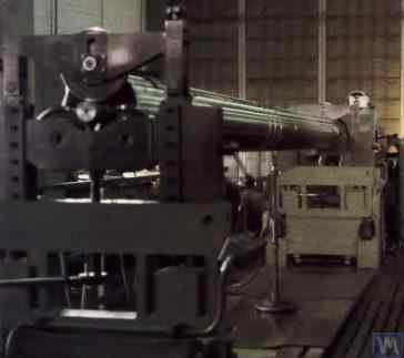
ਚਿੱਤਰ 2.15. "K. Schenk" ਦੀ ਹਾਰਡ ਬੇਅਰਿੰਗ ਬੈਲੈਂਸਿੰਗ ਮਸ਼ੀਨ
"Balanset" ਸੀਰੀਜ਼ ਯੰਤਰਾਂ ਲਈ ਗਾਹਕਾਂ ਤੋਂ ਪ੍ਰਾਪਤ ਬੇਨਤੀਆਂ ਦੇ ਵਿਸ਼ਲੇਸ਼ਣ ਤੋਂ ਪਤਾ ਲੱਗਦਾ ਹੈ ਕਿ ਅੰਦਰੂਨੀ ਵਰਤੋਂ ਲਈ ਹਾਰਡ ਬੇਅਰਿੰਗ ਮਸ਼ੀਨਾਂ ਬਣਾਉਣ ਵਿੱਚ ਦਿਲਚਸਪੀ ਲਗਾਤਾਰ ਵਧ ਰਹੀ ਹੈ। ਇਹ ਘਰੇਲੂ ਬੈਲੈਂਸਿੰਗ ਮਸ਼ੀਨਾਂ ਦੀਆਂ ਡਿਜ਼ਾਈਨ ਵਿਸ਼ੇਸ਼ਤਾਵਾਂ ਬਾਰੇ ਵਿਗਿਆਪਨ ਜਾਣਕਾਰੀ ਦੇ ਵਿਆਪਕ ਪ੍ਰਸਾਰ ਦੁਆਰਾ ਸੁਵਿਧਾਜਨਕ ਹੈ, ਜੋ ਸ਼ੌਕੀਨ ਨਿਰਮਾਤਾਵਾਂ ਦੁਆਰਾ ਆਪਣੇ ਵਿਕਾਸ ਲਈ ਐਨਾਲਾਗ (ਜਾਂ ਪ੍ਰੋਟੋਟਾਈਪ) ਵਜੋਂ ਵਰਤੀਆਂ ਜਾਂਦੀਆਂ ਹਨ।
ਆਓ "Balanset" ਸੀਰੀਜ਼ ਯੰਤਰਾਂ ਦੇ ਕਈ ਗਾਹਕਾਂ ਦੀਆਂ ਅੰਦਰੂਨੀ ਲੋੜਾਂ ਲਈ ਨਿਰਮਿਤ ਹਾਰਡ ਬੇਅਰਿੰਗ ਮਸ਼ੀਨਾਂ ਦੀਆਂ ਕੁਝ ਕਿਸਮਾਂ 'ਤੇ ਵਿਚਾਰ ਕਰੀਏ।
ਚਿੱਤਰ 2.16.a – 2.16.d ਡਰਾਈਵ ਸ਼ਾਫਟਾਂ ਨੂੰ ਬੈਲੈਂਸ ਕਰਨ ਲਈ ਤਿਆਰ ਕੀਤੀ ਗਈ ਇੱਕ ਹਾਰਡ ਬੇਅਰਿੰਗ ਮਸ਼ੀਨ ਦੀਆਂ ਫੋਟੋਆਂ ਦਿਖਾਉਂਦੇ ਹਨ, ਜੋ N. Obyedkov (ਮੈਗਨੀਟੋਗੋਰਸਕ ਸ਼ਹਿਰ) ਦੁਆਰਾ ਨਿਰਮਿਤ ਕੀਤੀ ਗਈ ਸੀ। ਜਿਵੇਂ ਕਿ ਚਿੱਤਰ 2.16.a ਵਿੱਚ ਦੇਖਿਆ ਗਿਆ ਹੈ, ਮਸ਼ੀਨ ਵਿੱਚ ਇੱਕ ਸਖ਼ਤ ਫਰੇਮ 1 ਹੈ, ਜਿਸ 'ਤੇ ਸਪੋਰਟ 2 (ਦੋ ਸਪਿੰਡਲ ਅਤੇ ਦੋ ਵਿਚਕਾਰਲੇ) ਲਗਾਏ ਗਏ ਹਨ। ਮਸ਼ੀਨ ਦੀ ਮੁੱਖ ਸਪਿੰਡਲ 3 ਨੂੰ ਇੱਕ ਬੈਲਟ ਡਰਾਈਵ ਰਾਹੀਂ ਇੱਕ ਅਸਿੰਕ੍ਰੋਨਸ ਇਲੈਕਟ੍ਰਿਕ ਮੋਟਰ 4 ਦੁਆਰਾ ਘੁੰਮਾਇਆ ਜਾਂਦਾ ਹੈ। ਇਲੈਕਟ੍ਰਿਕ ਮੋਟਰ 4 ਦੀ ਘੁੰਮਣ ਗਤੀ ਨੂੰ ਕੰਟਰੋਲ ਕਰਨ ਲਈ ਇੱਕ ਫ੍ਰੀਕੁਐਂਸੀ ਕੰਟਰੋਲਰ 6 ਵਰਤਿਆ ਜਾਂਦਾ ਹੈ। ਮਸ਼ੀਨ "Balanset 4" ਮਾਪਣ ਅਤੇ ਗਣਨਾ ਪ੍ਰਣਾਲੀ 5 ਨਾਲ ਲੈਸ ਹੈ, ਜਿਸ ਵਿੱਚ ਇੱਕ ਮਾਪਣ ਯੂਨਿਟ, ਇੱਕ ਕੰਪਿਊਟਰ, ਚਾਰ ਫੋਰਸ ਸੈਂਸਰ ਅਤੇ ਇੱਕ ਫੇਜ਼ ਐਂਗਲ ਸੈਂਸਰ ਸ਼ਾਮਲ ਹੈ (ਸੈਂਸਰ ਚਿੱਤਰ 2.16.a ਵਿੱਚ ਨਹੀਂ ਦਿਖਾਏ ਗਏ)।
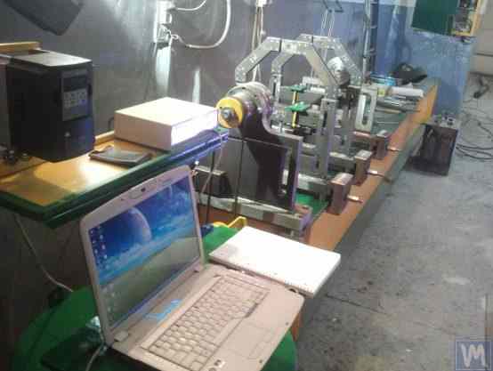
ਚਿੱਤਰ 2.16.a. N. Obyedkov (Magnitogorsk) ਦੁਆਰਾ ਨਿਰਮਿਤ, ਡਰਾਈਵ ਸ਼ਾਫਟਾਂ ਦੇ ਸੰਤੁਲਨ ਲਈ ਹਾਰਡ ਬੇਅਰਿੰਗ ਮਸ਼ੀਨ
ਚਿੱਤਰ 2.16.b ਮਸ਼ੀਨ ਦੇ ਅੱਗੇ ਵਾਲੇ ਸਪੋਰਟ ਦੀ ਫੋਟੋ ਦਿਖਾਉਂਦਾ ਹੈ, ਜਿਸ ਵਿੱਚ ਲੀਡਿੰਗ ਸਪਿੰਡਲ 3 ਹੈ, ਜੋ, ਜਿਵੇਂ ਪਹਿਲਾਂ ਦੱਸਿਆ ਗਿਆ ਹੈ, ਇੱਕ ਅਸਿੰਕ੍ਰੋਨਸ ਇਲੈਕਟ੍ਰਿਕ ਮੋਟਰ 4 ਤੋਂ ਬੈਲਟ ਡਰਾਈਵ ਦੁਆਰਾ ਚਲਾਇਆ ਜਾਂਦਾ ਹੈ। ਇਹ ਸਪੋਰਟ ਫਰੇਮ 'ਤੇ ਸਖ਼ਤੀ ਨਾਲ ਲਗਾਇਆ ਗਿਆ ਹੈ।
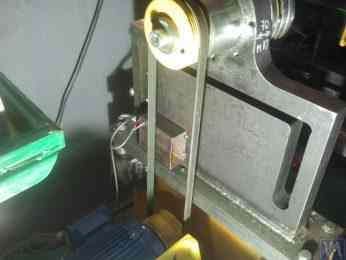
ਚਿੱਤਰ 2.16.b. ਅਗਲਾ (ਲੀਡਿੰਗ) ਸਪਿੰਡਲ ਸਪੋਰਟ।
ਚਿੱਤਰ 2.16.c ਮਸ਼ੀਨ ਦੇ ਦੋ ਚਲਣਯੋਗ ਇੰਟਰਮੀਡੀਏਟ ਸਪੋਰਟਾਂ ਵਿੱਚੋਂ ਇੱਕ ਦੀ ਫੋਟੋ ਦਿਖਾਉਂਦਾ ਹੈ। ਇਹ ਸਪੋਰਟ ਸਲਾਈਡਾਂ 7 ਉੱਤੇ ਟਿਕੀ ਹੁੰਦੀ ਹੈ, ਜੋ ਇਸਨੂੰ ਫਰੇਮ ਗਾਈਡਾਂ ਦੇ ਨਾਲ-ਨਾਲ ਲੰਬਾਈ ਦਿਸ਼ਾ ਵਿੱਚ ਖਿਸਕਣ ਦਿੰਦੀਆਂ ਹਨ। ਇਸ ਸਪੋਰਟ ਵਿੱਚ ਇੱਕ ਖਾਸ ਯੰਤਰ 8 ਸ਼ਾਮਲ ਹੈ, ਜੋ ਸੰਤੁਲਿਤ ਕੀਤੇ ਜਾ ਰਹੇ ਡਰਾਈਵ ਸ਼ਾਫਟ ਦੇ ਇੰਟਰਮੀਡੀਏਟ ਬੇਅਰਿੰਗ ਨੂੰ ਲਗਾਉਣ ਅਤੇ ਉਚਾਈ ਐਡਜਸਟ ਕਰਨ ਲਈ ਬਣਾਇਆ ਗਿਆ ਹੈ।
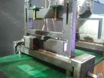
ਚਿੱਤਰ 2.16.c. ਮਸ਼ੀਨ ਦੀ ਇੰਟਰਮੀਡੀਏਟ ਚਲਣਯੋਗ ਸਪੋਰਟ
ਚਿੱਤਰ 2.16.d ਪਿਛਲੇ (ਡ੍ਰਿਵਨ) ਸਪਿੰਡਲ ਸਪੋਰਟ ਦੀ ਫੋਟੋ ਦਿਖਾਉਂਦਾ ਹੈ, ਜੋ, ਵਿਚਕਾਰਲੇ ਸਪੋਰਟਾਂ ਵਾਂਗ, ਮਸ਼ੀਨ ਫਰੇਮ ਦੀਆਂ ਗਾਈਡਾਂ ਦੇ ਨਾਲ-ਨਾਲ ਗਤੀ ਦੀ ਇਜਾਜ਼ਤ ਦਿੰਦਾ ਹੈ।
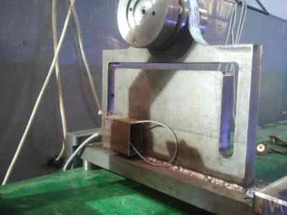
ਚਿੱਤਰ 2.16.d. ਪਿਛਲਾ (ਡਰਿਵਨ) ਸਪਿੰਡਲ ਸਪੋਰਟ।
ਉੱਪਰ ਦੱਸੀਆਂ ਗਈਆਂ ਸਾਰੀਆਂ ਸਪੋਰਟਾਂ ਫਲੈਟ ਬੇਸਾਂ ਉੱਤੇ ਲਗਾਈਆਂ ਗਈਆਂ ਵਰਟੀਕਲ ਪਲੇਟਾਂ ਹਨ। ਇਹਨਾਂ ਪਲੇਟਾਂ ਵਿੱਚ T-ਆਕਾਰ ਦੇ ਸਲਾਟ ਹਨ (ਦੇਖੋ ਚਿੱਤਰ 2.16.d), ਜੋ ਸਪੋਰਟ ਨੂੰ ਇੱਕ ਅੰਦਰਲੇ ਹਿੱਸੇ 9 (ਵਧੇਰੇ ਕਠੋਰ) ਅਤੇ ਇੱਕ ਬਾਹਰਲੇ ਹਿੱਸੇ 10 (ਘੱਟ ਕਠੋਰ) ਵਿੱਚ ਵੰਡਦੇ ਹਨ। ਸਪੋਰਟ ਦੇ ਅੰਦਰਲੇ ਅਤੇ ਬਾਹਰਲੇ ਹਿੱਸਿਆਂ ਦੀ ਵੱਖ-ਵੱਖ ਕਠੋਰਤਾ ਕਾਰਨ ਸੰਤੁਲਿਤ ਕੀਤੇ ਜਾ ਰਹੇ ਰੋਟਰ ਦੀਆਂ ਅਸੰਤੁਲਨ ਬਲਾਂ ਦੇ ਪ੍ਰਭਾਵ ਹੇਠ ਇਹਨਾਂ ਹਿੱਸਿਆਂ ਦਾ ਸਾਪੇਖਿਕ ਵਿਗਾੜ ਹੋ ਸਕਦਾ ਹੈ।
ਘਰੇਲੂ (ਹੋਮਮੇਡ) ਮਸ਼ੀਨਾਂ ਵਿੱਚ ਸਪੋਰਟਾਂ ਦੇ ਸਾਪੇਖਿਕ ਵਿਗਾੜ ਨੂੰ ਮਾਪਣ ਲਈ ਆਮ ਤੌਰ 'ਤੇ ਫੋਰਸ ਸੈਂਸਰ ਵਰਤੇ ਜਾਂਦੇ ਹਨ। ਇੱਕ ਹਾਰਡ ਬੇਅਰਿੰਗ ਸੰਤੁਲਨ ਮਸ਼ੀਨ ਸਪੋਰਟ ਉੱਤੇ ਫੋਰਸ ਸੈਂਸਰ ਲਗਾਉਣ ਦੀ ਉਦਾਹਰਨ ਚਿੱਤਰ 2.16.e ਵਿੱਚ ਦਿਖਾਈ ਗਈ ਹੈ। ਜਿਵੇਂ ਕਿ ਇਸ ਚਿੱਤਰ ਵਿੱਚ ਦੇਖਿਆ ਜਾ ਸਕਦਾ ਹੈ, ਫੋਰਸ ਸੈਂਸਰ 11 ਨੂੰ ਬੋਲਟ 12 ਦੁਆਰਾ ਸਪੋਰਟ ਦੇ ਅੰਦਰਲੇ ਹਿੱਸੇ ਦੀ ਸਾਈਡ ਸਤ੍ਹਾ ਨਾਲ ਦਬਾਇਆ ਜਾਂਦਾ ਹੈ, ਜੋ ਸਪੋਰਟ ਦੇ ਬਾਹਰਲੇ ਹਿੱਸੇ ਵਿੱਚ ਥਰੈੱਡਡ ਹੋਲ ਵਿੱਚੋਂ ਲੰਘਦਾ ਹੈ।
ਫੋਰਸ ਸੈਂਸਰ 11 ਦੇ ਪੂਰੇ ਪਲੇਨ ਉੱਤੇ ਬੋਲਟ 12 ਦਾ ਸਮਾਨ ਦਬਾਅ ਯਕੀਨੀ ਬਣਾਉਣ ਲਈ, ਇਸਦੇ ਅਤੇ ਸੈਂਸਰ ਦੇ ਵਿਚਕਾਰ ਇੱਕ ਫਲੈਟ ਵਾਸ਼ਰ 13 ਲਗਾਈ ਜਾਂਦੀ ਹੈ।
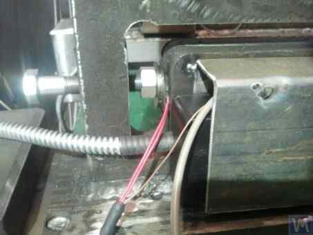
ਚਿੱਤਰ 2.16.d. ਸਪੋਰਟ ਉੱਤੇ ਫੋਰਸ ਸੈਂਸਰ ਲਗਾਉਣ ਦੀ ਉਦਾਹਰਨ।
ਮਸ਼ੀਨ ਦੇ ਸੰਚਾਲਨ ਦੌਰਾਨ, ਬੈਲੈਂਸ ਕੀਤੇ ਜਾ ਰਹੇ ਰੋਟਰ ਤੋਂ ਅਸੰਤੁਲਨ ਦੀਆਂ ਸ਼ਕਤੀਆਂ ਸਪੋਰਟ ਯੂਨਿਟਾਂ (ਸਪਿੰਡਲ ਜਾਂ ਵਿਚਕਾਰਲੇ ਬੇਅਰਿੰਗਾਂ) ਰਾਹੀਂ ਸਪੋਰਟ ਦੇ ਬਾਹਰੀ ਹਿੱਸੇ 'ਤੇ ਕੰਮ ਕਰਦੀਆਂ ਹਨ, ਜੋ ਰੋਟਰ ਦੀ ਘੁੰਮਣ ਬਾਰੰਬਾਰਤਾ 'ਤੇ ਇਸਦੇ ਅੰਦਰੂਨੀ ਹਿੱਸੇ ਦੇ ਸਾਪੇਖ ਚੱਕਰੀ ਤੌਰ 'ਤੇ ਹਿੱਲਣਾ (ਵਿਗੜਨਾ) ਸ਼ੁਰੂ ਕਰ ਦਿੰਦਾ ਹੈ। ਇਸ ਦੇ ਨਤੀਜੇ ਵਜੋਂ ਸੈਂਸਰ 11 'ਤੇ ਇੱਕ ਪਰਿਵਰਤਨਸ਼ੀਲ ਸ਼ਕਤੀ ਲੱਗਦੀ ਹੈ, ਜੋ ਅਸੰਤੁਲਨ ਸ਼ਕਤੀ ਦੇ ਅਨੁਪਾਤਿਕ ਹੁੰਦੀ ਹੈ। ਇਸਦੇ ਪ੍ਰਭਾਵ ਹੇਠ, ਫੋਰਸ ਸੈਂਸਰ ਦੇ ਆਉਟਪੁੱਟ 'ਤੇ ਰੋਟਰ ਦੇ ਅਸੰਤੁਲਨ ਦੀ ਮਾਤਰਾ ਦੇ ਅਨੁਪਾਤਿਕ ਇੱਕ ਬਿਜਲਈ ਸਿਗਨਲ ਪੈਦਾ ਹੁੰਦਾ ਹੈ।
ਸਾਰੇ ਸਪੋਰਟਾਂ 'ਤੇ ਲਗਾਏ ਗਏ ਫੋਰਸ ਸੈਂਸਰਾਂ ਤੋਂ ਸਿਗਨਲ ਮਸ਼ੀਨ ਦੀ ਮਾਪਣ ਅਤੇ ਗਣਨਾ ਪ੍ਰਣਾਲੀ ਵਿੱਚ ਭੇਜੇ ਜਾਂਦੇ ਹਨ, ਜਿੱਥੇ ਇਹਨਾਂ ਦੀ ਵਰਤੋਂ ਸੁਧਾਰਕ ਵਜ਼ਨਾਂ ਦੇ ਪੈਰਾਮੀਟਰ ਨਿਰਧਾਰਤ ਕਰਨ ਲਈ ਕੀਤੀ ਜਾਂਦੀ ਹੈ।
ਚਿੱਤਰ 2.17.a. "ਸਕ੍ਰੂ" ਸ਼ਾਫਟਾਂ ਨੂੰ ਬੈਲੈਂਸ ਕਰਨ ਲਈ ਵਰਤੀ ਜਾਂਦੀ ਇੱਕ ਵਿਸ਼ੇਸ਼ ਹਾਰਡ ਬੇਅਰਿੰਗ ਮਸ਼ੀਨ ਦੀ ਫੋਟੋ ਪੇਸ਼ ਕਰਦਾ ਹੈ। ਇਹ ਮਸ਼ੀਨ LLC "Ufatverdosplav" ਵਿਖੇ ਅੰਦਰੂਨੀ ਵਰਤੋਂ ਲਈ ਨਿਰਮਿਤ ਕੀਤੀ ਗਈ ਸੀ।
ਜਿਵੇਂ ਕਿ ਚਿੱਤਰ ਵਿੱਚ ਦੇਖਿਆ ਜਾ ਸਕਦਾ ਹੈ, ਮਸ਼ੀਨ ਦੇ ਸਪਿਨ-ਅੱਪ ਮਕੈਨਿਜ਼ਮ ਦਾ ਇੱਕ ਸਰਲ ਨਿਰਮਾਣ ਹੈ, ਜਿਸ ਵਿੱਚ ਹੇਠ ਲਿਖੇ ਮੁੱਖ ਹਿੱਸੇ ਸ਼ਾਮਲ ਹਨ:
- ਵੈਲਡਿਡ ਫਰੇਮ 1, ਜੋ ਬੈੱਡ ਦੇ ਤੌਰ 'ਤੇ ਕੰਮ ਕਰਦਾ ਹੈ;
- ਦੋ ਸਥਿਰ ਸਪੋਰਟਾਂ 2, ਜੋ ਫਰੇਮ ਨਾਲ ਸਖਤੀ ਨਾਲ ਜੁੜੀਆਂ ਹੋਈਆਂ ਹਨ;
- ਇਲੈਕਟ੍ਰਿਕ ਮੋਟਰ 3, ਜੋ ਬੈਲਟ ਡਰਾਈਵ 4 ਰਾਹੀਂ ਸੰਤੁਲਿਤ ਕੀਤੇ ਜਾ ਰਹੇ ਸ਼ਾਫਟ (ਸਕ੍ਰੂ) 5 ਨੂੰ ਚਲਾਉਂਦਾ ਹੈ।
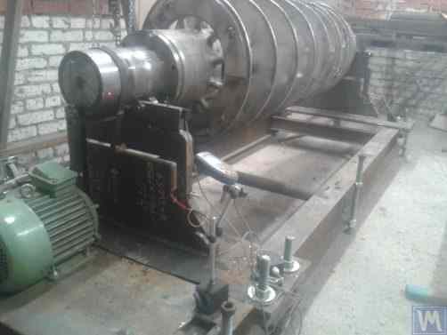
ਚਿੱਤਰ 2.17.a. LLC "Ufatverdosplav" ਦੁਆਰਾ ਨਿਰਮਿਤ, ਸਕ੍ਰੂ ਸ਼ਾਫਟਾਂ ਦੀ ਬੈਲੈਂਸਿੰਗ ਲਈ ਹਾਰਡ ਬੇਅਰਿੰਗ ਮਸ਼ੀਨ
ਮਸ਼ੀਨ ਦੀਆਂ ਸਪੋਰਟਾਂ 2 T-ਆਕਾਰ ਦੇ ਸਲਾਟਾਂ ਵਾਲੀਆਂ ਵਰਟੀਕਲ ਲਗਾਈਆਂ ਗਈਆਂ ਸਟੀਲ ਪਲੇਟਾਂ ਹਨ। ਹਰੇਕ ਸਪੋਰਟ ਦੇ ਸਿਖਰ 'ਤੇ, ਰੋਲਿੰਗ ਬੇਅਰਿੰਗਾਂ ਦੀ ਵਰਤੋਂ ਕਰਕੇ ਬਣਾਏ ਗਏ ਸਪੋਰਟ ਰੋਲਰ ਹਨ, ਜਿਹਨਾਂ ਉੱਤੇ ਸੰਤੁਲਿਤ ਕੀਤਾ ਜਾ ਰਿਹਾ ਸ਼ਾਫਟ 5 ਘੁੰਮਦਾ ਹੈ।
ਰੋਟਰ ਅਸੰਤੁਲਨ ਦੀ ਕਿਰਿਆ ਹੇਠ ਹੋਣ ਵਾਲੀ ਸਪੋਰਟਾਂ ਦੀ ਵਿਗਾੜ ਨੂੰ ਮਾਪਣ ਲਈ, ਫੋਰਸ ਸੈਂਸਰ 6 ਵਰਤੇ ਜਾਂਦੇ ਹਨ (ਵੇਖੋ ਚਿੱਤਰ 2.17.b), ਜੋ ਸਪੋਰਟਾਂ ਦੇ ਸਲਾਟਾਂ ਵਿੱਚ ਲਗਾਏ ਜਾਂਦੇ ਹਨ। ਇਹ ਸੈਂਸਰ "Balanset 1" ਯੰਤਰ ਨਾਲ ਜੁੜੇ ਹੋਏ ਹਨ, ਜੋ ਇਸ ਮਸ਼ੀਨ 'ਤੇ ਮਾਪਣ ਅਤੇ ਗਣਨਾ ਪ੍ਰਣਾਲੀ ਵਜੋਂ ਵਰਤਿਆ ਜਾਂਦਾ ਹੈ।
ਮਸ਼ੀਨ ਦੇ ਸਪਿਨ-ਅੱਪ ਵਿਧੀ ਦੀ ਸਾਪੇਖਿਕ ਸਾਦਗੀ ਦੇ ਬਾਵਜੂਦ, ਇਹ ਸਕ੍ਰੂਆਂ ਦੀ ਕਾਫ਼ੀ ਉੱਚ-ਗੁਣਵੱਤਾ ਵਾਲੀ ਬੈਲੈਂਸਿੰਗ ਨੂੰ ਸਮਰੱਥ ਬਣਾਉਂਦਾ ਹੈ, ਜਿਨ੍ਹਾਂ ਦੀ, ਜਿਵੇਂ ਕਿ ਚਿੱਤਰ 2.17.a. ਵਿੱਚ ਦੇਖਿਆ ਗਿਆ ਹੈ, ਇੱਕ ਗੁੰਝਲਦਾਰ ਹੈਲੀਕਲ ਸਤਹ ਹੁੰਦੀ ਹੈ।
LLC "Ufatverdosplav" ਦੇ ਅਨੁਸਾਰ, ਬੈਲੈਂਸਿੰਗ ਪ੍ਰਕਿਰਿਆ ਦੌਰਾਨ ਇਸ ਮਸ਼ੀਨ 'ਤੇ ਸਕ੍ਰੂ ਦਾ ਸ਼ੁਰੂਆਤੀ ਅਸੰਤੁਲਨ ਲਗਭਗ 50 ਗੁਣਾ ਘਟਾਇਆ ਗਿਆ ਸੀ।
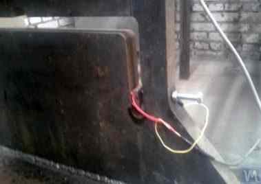
ਚਿੱਤਰ 2.17.b. ਸਕ੍ਰੂ ਸ਼ਾਫਟਾਂ ਨੂੰ ਸੰਤੁਲਿਤ ਕਰਨ ਲਈ ਫੋਰਸ ਸੈਂਸਰ ਵਾਲੀ ਹਾਰਡ ਬੇਅਰਿੰਗ ਮਸ਼ੀਨ ਸਪੋਰਟ
ਸਕ੍ਰੂ ਦੇ ਪਹਿਲੇ ਪਲੇਨ ਵਿੱਚ ਪ੍ਰਾਪਤ ਕੀਤਾ ਗਿਆ ਬਾਕੀ ਬਚਿਆ ਅਸੰਤੁਲਨ 3552 g*mm (185 mm ਦੇ ਰੇਡੀਅਸ 'ਤੇ 19.2 g) ਸੀ, ਅਤੇ ਦੂਜੇ ਪਲੇਨ ਵਿੱਚ 2220 g*mm (185 mm ਦੇ ਰੇਡੀਅਸ 'ਤੇ 12.0 g) ਸੀ। 500 kg ਭਾਰ ਵਾਲੇ ਅਤੇ 3500 RPM ਦੀ ਰੋਟੇਸ਼ਨਲ ਫ੍ਰੀਕੁਐਂਸੀ 'ਤੇ ਸੰਚਾਲਿਤ ਰੋਟਰ ਲਈ, ਇਹ ਅਸੰਤੁਲਨ ISO 21940-11 (ਪਹਿਲਾਂ ISO 1940-1) ਅਨੁਸਾਰ ਸ਼੍ਰੇਣੀ G6.3 ਨਾਲ ਮੇਲ ਖਾਂਦਾ ਹੈ, ਜੋ ਇਸ ਦੇ ਤਕਨੀਕੀ ਦਸਤਾਵੇਜ਼ਾਂ ਵਿੱਚ ਦੱਸੀਆਂ ਲੋੜਾਂ ਨੂੰ ਪੂਰਾ ਕਰਦਾ ਹੈ।
S.V. Morozov ਦੁਆਰਾ ਪ੍ਰਸਤਾਵਿਤ ਇੱਕ ਮੌਲਿਕ ਡਿਜ਼ਾਈਨ (ਵੇਖੋ ਚਿੱਤਰ 2.18), ਜਿਸ ਵਿੱਚ ਵੱਖ-ਵੱਖ ਆਕਾਰਾਂ ਦੀਆਂ ਦੋ ਹਾਰਡ ਬੇਅਰਿੰਗ ਬੈਲੈਂਸਿੰਗ ਮਸ਼ੀਨਾਂ ਦੇ ਸਪੋਰਟਾਂ ਦੀ ਇੱਕੋ ਸਮੇਂ ਸਥਾਪਨਾ ਲਈ ਇੱਕ ਸਿੰਗਲ ਬੇਸ ਦੀ ਵਰਤੋਂ ਸ਼ਾਮਲ ਹੈ। ਇਸ ਤਕਨੀਕੀ ਹੱਲ ਦੇ ਸਪੱਸ਼ਟ ਫਾਇਦੇ, ਜੋ ਨਿਰਮਾਤਾ ਦੀ ਉਤਪਾਦਨ ਲਾਗਤ ਨੂੰ ਘੱਟ ਕਰਨ ਵਿੱਚ ਮਦਦ ਕਰਦੇ ਹਨ, ਵਿੱਚ ਸ਼ਾਮਲ ਹਨ:
- ਉਤਪਾਦਨ ਥਾਂ ਦੀ ਬਚਤ;
- ਦੋ ਵੱਖ-ਵੱਖ ਮਸ਼ੀਨਾਂ ਨੂੰ ਚਲਾਉਣ ਲਈ ਵੇਰੀਏਬਲ ਫ੍ਰੀਕੁਐਂਸੀ ਡਰਾਈਵ ਵਾਲੀ ਇੱਕ ਇਲੈਕਟ੍ਰਿਕ ਮੋਟਰ ਦੀ ਵਰਤੋਂ;
- ਦੋ ਵੱਖ-ਵੱਖ ਮਸ਼ੀਨਾਂ ਨੂੰ ਚਲਾਉਣ ਲਈ ਇੱਕ ਮਾਪਣ ਪ੍ਰਣਾਲੀ ਦੀ ਵਰਤੋਂ।

ਚਿੱਤਰ 2.18. S.V. Morozov ਦੁਆਰਾ ਨਿਰਮਿਤ ਹਾਰਡ ਬੇਅਰਿੰਗ ਬੈਲੈਂਸਿੰਗ ਮਸ਼ੀਨ ("ਟੈਂਡਮ")
3. ਬੈਲੇਂਸਿੰਗ ਮਸ਼ੀਨਾਂ ਦੇ ਬੁਨਿਆਦੀ ਯੂਨਿਟਾਂ ਅਤੇ ਮਕੈਨਿਜ਼ਮਾਂ ਦੇ ਨਿਰਮਾਣ ਲਈ ਲੋੜਾਂ
3.1. ਬੇਅਰਿੰਗਾਂ
3.1.1. ਬੇਅਰਿੰਗ ਡਿਜ਼ਾਈਨ ਦੇ ਸਿਧਾਂਤਕ ਆਧਾਰ
ਪਿਛਲੇ ਭਾਗ ਵਿੱਚ, ਬੈਲੈਂਸਿੰਗ ਮਸ਼ੀਨਾਂ ਲਈ ਸਾਫ਼ਟ ਬੇਅਰਿੰਗ ਅਤੇ ਹਾਰਡ ਬੇਅਰਿੰਗ ਸਪੋਰਟਾਂ ਦੇ ਮੁੱਖ ਡਿਜ਼ਾਈਨ ਸੰਸਕਰਣਾਂ ਦੀ ਵਿਸਥਾਰ ਵਿੱਚ ਚਰਚਾ ਕੀਤੀ ਗਈ ਸੀ। ਡਿਜ਼ਾਈਨਰਾਂ ਨੂੰ ਇਹਨਾਂ ਸਪੋਰਟਾਂ ਨੂੰ ਡਿਜ਼ਾਈਨ ਅਤੇ ਨਿਰਮਾਣ ਕਰਦੇ ਸਮੇਂ ਜਿਸ ਮੁੱਖ ਪੈਰਾਮੀਟਰ 'ਤੇ ਵਿਚਾਰ ਕਰਨਾ ਚਾਹੀਦਾ ਹੈ, ਉਹ ਹੈ ਇਹਨਾਂ ਦੀ ਓਸੀਲੇਸ਼ਨ ਦੀ ਕੁਦਰਤੀ ਬਾਰੰਬਾਰਤਾ। ਇਹ ਇਸ ਲਈ ਮਹੱਤਵਪੂਰਨ ਹੈ ਕਿਉਂਕਿ ਮਸ਼ੀਨ ਦੀਆਂ ਮਾਪਣ ਅਤੇ ਗਣਨਾ ਪ੍ਰਣਾਲੀਆਂ ਦੁਆਰਾ ਸੁਧਾਰਕ ਵਜ਼ਨਾਂ ਦੇ ਪੈਰਾਮੀਟਰ ਗਣਨਾ ਕਰਨ ਲਈ ਨਾ ਸਿਰਫ ਸਪੋਰਟਾਂ ਦੇ ਵਾਈਬ੍ਰੇਸ਼ਨ (ਚੱਕਰੀ ਵਿਗਾੜ) ਦੇ ਐਂਪਲੀਟਿਊਡ ਦਾ, ਸਗੋਂ ਵਾਈਬ੍ਰੇਸ਼ਨ ਦੇ ਫੇਜ਼ ਦਾ ਵੀ ਮਾਪ ਲੋੜੀਂਦਾ ਹੈ।
ਜੇਕਰ ਕਿਸੇ ਸਪੋਰਟ ਦੀ ਕੁਦਰਤੀ ਬਾਰੰਬਾਰਤਾ ਬੈਲੈਂਸ ਕੀਤੇ ਜਾ ਰਹੇ ਰੋਟਰ ਦੀ ਘੁੰਮਣ ਬਾਰੰਬਾਰਤਾ ਨਾਲ ਮੇਲ ਖਾਂਦੀ ਹੈ (ਸਪੋਰਟ ਰੈਜ਼ੋਨੈਂਸ), ਤਾਂ ਵਾਈਬ੍ਰੇਸ਼ਨ ਦੇ ਐਂਪਲੀਟਿਊਡ ਅਤੇ ਫੇਜ਼ ਦਾ ਸਹੀ ਮਾਪ ਲਗਭਗ ਅਸੰਭਵ ਹੈ। ਇਹ ਗ੍ਰਾਫਾਂ ਵਿੱਚ ਸਪਸ਼ਟ ਤੌਰ 'ਤੇ ਦਰਸਾਇਆ ਗਿਆ ਹੈ ਜੋ ਬੈਲੈਂਸ ਕੀਤੇ ਜਾ ਰਹੇ ਰੋਟਰ ਦੀ ਘੁੰਮਣ ਬਾਰੰਬਾਰਤਾ ਦੇ ਫੰਕਸ਼ਨ ਵਜੋਂ ਸਪੋਰਟ ਦੇ ਓਸੀਲੇਸ਼ਨਾਂ ਦੇ ਐਂਪਲੀਟਿਊਡ ਅਤੇ ਫੇਜ਼ ਵਿੱਚ ਤਬਦੀਲੀਆਂ ਦਿਖਾਉਂਦੇ ਹਨ (ਵੇਖੋ ਚਿੱਤਰ 3.1)।
ਇਹਨਾਂ ਗ੍ਰਾਫਾਂ ਤੋਂ ਇਹ ਸਪਸ਼ਟ ਹੁੰਦਾ ਹੈ ਕਿ ਜਦੋਂ ਸੰਤੁਲਿਤ ਕੀਤੇ ਜਾ ਰਹੇ ਰੋਟਰ ਦੀ ਘੁੰਮਣ ਫ੍ਰੀਕੁਐਂਸੀ ਸਪੋਰਟ ਦੀਆਂ ਕੁਦਰਤੀ ਓਸਿਲੇਸ਼ਨਾਂ ਦੀ ਫ੍ਰੀਕੁਐਂਸੀ ਦੇ ਨੇੜੇ ਪਹੁੰਚਦੀ ਹੈ (ਯਾਨੀ ਜਦੋਂ ਅਨੁਪਾਤ fp/fo 1 ਦੇ ਨੇੜੇ ਹੁੰਦਾ ਹੈ), ਤਾਂ ਸਪੋਰਟ ਦੀਆਂ ਰੈਜ਼ੋਨੈਂਸ ਓਸਿਲੇਸ਼ਨਾਂ ਨਾਲ ਸਬੰਧਤ ਐਪਲੀਟਿਊਡ ਵਿੱਚ ਕਾਫ਼ੀ ਵਾਧਾ ਹੁੰਦਾ ਹੈ (ਦੇਖੋ ਚਿੱਤਰ 3.1.a)। ਇਸਦੇ ਨਾਲ ਹੀ, ਗ੍ਰਾਫ 3.1.b ਦਿਖਾਉਂਦਾ ਹੈ ਕਿ ਰੈਜ਼ੋਨੈਂਸ ਜ਼ੋਨ ਵਿੱਚ, ਫੇਜ਼ ਐਂਗਲ ∆F° ਵਿੱਚ ਇੱਕ ਤਿੱਖੀ ਤਬਦੀਲੀ ਆਉਂਦੀ ਹੈ, ਜੋ 180° ਤੱਕ ਪਹੁੰਚ ਸਕਦੀ ਹੈ।
ਦੂਜੇ ਸ਼ਬਦਾਂ ਵਿੱਚ, ਜਦੋਂ ਕਿਸੇ ਵੀ ਮਕੈਨਿਜ਼ਮ ਨੂੰ ਰੈਜ਼ੋਨੈਂਸ ਜ਼ੋਨ ਵਿੱਚ ਸੰਤੁਲਿਤ ਕੀਤਾ ਜਾਂਦਾ ਹੈ, ਤਾਂ ਇਸਦੀ ਘੁੰਮਣ ਫ੍ਰੀਕੁਐਂਸੀ ਵਿੱਚ ਛੋਟੀਆਂ ਤਬਦੀਲੀਆਂ ਵੀ ਵਾਈਬ੍ਰੇਸ਼ਨ ਦੇ ਐਪਲੀਟਿਊਡ ਅਤੇ ਫੇਜ਼ ਦੇ ਮਾਪ ਨਤੀਜਿਆਂ ਵਿੱਚ ਵੱਡੀ ਅਸਥਿਰਤਾ ਲਿਆ ਸਕਦੀਆਂ ਹਨ, ਜਿਸ ਨਾਲ ਸੁਧਾਰਕ ਵਜ਼ਨਾਂ ਦੇ ਪੈਰਾਮੀਟਰਾਂ ਦੀ ਗਣਨਾ ਵਿੱਚ ਗਲਤੀਆਂ ਹੁੰਦੀਆਂ ਹਨ ਅਤੇ ਸੰਤੁਲਨ ਦੀ ਗੁਣਵੱਤਾ ਉੱਤੇ ਮਾੜਾ ਅਸਰ ਪੈਂਦਾ ਹੈ।
ਉਪਰੋਕਤ ਗ੍ਰਾਫ਼ ਪਹਿਲਾਂ ਦਿੱਤੀਆਂ ਸਿਫਾਰਸ਼ਾਂ ਦੀ ਪੁਸ਼ਟੀ ਕਰਦੇ ਹਨ ਕਿ ਹਾਰਡ ਬੇਅਰਿੰਗ ਮਸ਼ੀਨਾਂ ਲਈ, ਰੋਟਰ ਦੀਆਂ ਕਾਰਜਸ਼ੀਲ ਬਾਰੰਬਾਰਤਾਵਾਂ ਦੀ ਉਪਰਲੀ ਸੀਮਾ ਸਪੋਰਟ ਦੀ ਕੁਦਰਤੀ ਬਾਰੰਬਾਰਤਾ, fo, ਨਾਲੋਂ (ਘੱਟੋ-ਘੱਟ) 2-3 ਗੁਣਾ ਘੱਟ ਹੋਣੀ ਚਾਹੀਦੀ ਹੈ। ਸਾਫ਼ਟ ਬੇਅਰਿੰਗ ਮਸ਼ੀਨਾਂ ਲਈ, ਬੈਲੈਂਸ ਕੀਤੇ ਜਾ ਰਹੇ ਰੋਟਰ ਦੀਆਂ ਮਨਜ਼ੂਰਸ਼ੁਦਾ ਕਾਰਜਸ਼ੀਲ ਬਾਰੰਬਾਰਤਾਵਾਂ ਦੀ ਹੇਠਲੀ ਸੀਮਾ ਸਪੋਰਟ ਦੀ ਕੁਦਰਤੀ ਬਾਰੰਬਾਰਤਾ ਨਾਲੋਂ (ਘੱਟੋ-ਘੱਟ) 2-3 ਗੁਣਾ ਵੱਧ ਹੋਣੀ ਚਾਹੀਦੀ ਹੈ।
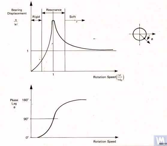
ਚਿੱਤਰ 3.1. ਘੁੰਮਣ ਫ੍ਰੀਕੁਐਂਸੀ ਵਿੱਚ ਤਬਦੀਲੀਆਂ ਦੇ ਫੰਕਸ਼ਨ ਵਜੋਂ ਸੰਤੁਲਨ ਮਸ਼ੀਨ ਸਪੋਰਟ ਦੇ ਸਾਪੇਖਿਕ ਐਪਲੀਟਿਊਡ ਅਤੇ ਵਾਈਬ੍ਰੇਸ਼ਨ ਦੇ ਫੇਜ਼ ਵਿੱਚ ਤਬਦੀਲੀਆਂ ਦਿਖਾਉਂਦੇ ਗ੍ਰਾਫ।
- Ад – ਸਪੋਰਟ ਦੇ ਡਾਇਨਾਮਿਕ ਵਾਈਬ੍ਰੇਸ਼ਨਾਂ ਦਾ ਐਪਲੀਟਿਊਡ;
- e = m*r / M - ਬੈਲੈਂਸ ਕੀਤੇ ਜਾ ਰਹੇ ਰੋਟਰ ਦਾ ਵਿਸ਼ੇਸ਼ ਅਸੰਤੁਲਨ;
- m – ਰੋਟਰ ਦਾ ਅਸੰਤੁਲਿਤ ਪੁੰਜ;
- M – ਰੋਟਰ ਦਾ ਪੁੰਜ;
- r – ਉਹ ਰੇਡੀਅਸ ਜਿਸ ਉੱਤੇ ਅਸੰਤੁਲਿਤ ਪੁੰਜ ਰੋਟਰ ਉੱਤੇ ਸਥਿਤ ਹੈ;
- fp – ਰੋਟਰ ਦੀ ਘੁੰਮਣ ਫ੍ਰੀਕੁਐਂਸੀ;
- fo – ਸਪੋਰਟ ਦੀਆਂ ਵਾਈਬ੍ਰੇਸ਼ਨਾਂ ਦੀ ਕੁਦਰਤੀ ਫ੍ਰੀਕੁਐਂਸੀ
ਦਿੱਤੀ ਗਈ ਜਾਣਕਾਰੀ ਦੇ ਆਧਾਰ 'ਤੇ, ਮਸ਼ੀਨ ਨੂੰ ਇਸਦੀਆਂ ਸਪੋਰਟਾਂ ਦੇ ਰੈਜ਼ੋਨੈਂਸ ਖੇਤਰ ਵਿੱਚ ਚਲਾਉਣ ਦੀ ਸਿਫਾਰਸ਼ ਨਹੀਂ ਕੀਤੀ ਜਾਂਦੀ (ਚਿੱਤਰ 3.1 ਵਿੱਚ ਲਾਲ ਰੰਗ ਵਿੱਚ ਦਰਸਾਇਆ ਗਿਆ)। ਚਿੱਤਰ 3.1 ਵਿੱਚ ਦਿਖਾਏ ਗਏ ਗ੍ਰਾਫ ਇਹ ਵੀ ਦਰਸਾਉਂਦੇ ਹਨ ਕਿ ਰੋਟਰ ਦੇ ਇੱਕੋ ਜਿਹੇ ਅਸੰਤੁਲਨ ਲਈ, ਸਾਫਟ ਬੇਅਰਿੰਗ ਮਸ਼ੀਨ ਸਪੋਰਟਾਂ ਦੀਆਂ ਅਸਲ ਵਾਈਬ੍ਰੇਸ਼ਨਾਂ ਸਾਫਟ ਬੇਅਰਿੰਗ ਮਸ਼ੀਨ ਸਪੋਰਟਾਂ ਉੱਤੇ ਹੋਣ ਵਾਲੀਆਂ ਵਾਈਬ੍ਰੇਸ਼ਨਾਂ ਨਾਲੋਂ ਕਾਫ਼ੀ ਘੱਟ ਹੁੰਦੀਆਂ ਹਨ।
ਇਸ ਤੋਂ ਇਹ ਸਿੱਟਾ ਨਿਕਲਦਾ ਹੈ ਕਿ ਹਾਰਡ ਬੇਅਰਿੰਗ ਮਸ਼ੀਨਾਂ ਵਿੱਚ ਸਪੋਰਟਾਂ ਦੀਆਂ ਵਾਈਬ੍ਰੇਸ਼ਨਾਂ ਮਾਪਣ ਲਈ ਵਰਤੇ ਜਾਣ ਵਾਲੇ ਸੈਂਸਰਾਂ ਵਿੱਚ ਸਾਫਟ ਬੇਅਰਿੰਗ ਮਸ਼ੀਨਾਂ ਦੇ ਸੈਂਸਰਾਂ ਨਾਲੋਂ ਵੱਧ ਸੰਵੇਦਨਸ਼ੀਲਤਾ ਹੋਣੀ ਚਾਹੀਦੀ ਹੈ। ਇਹ ਸਿੱਟਾ ਸੈਂਸਰਾਂ ਦੀ ਵਰਤੋਂ ਦੇ ਅਸਲ ਅਭਿਆਸ ਦੁਆਰਾ ਚੰਗੀ ਤਰ੍ਹਾਂ ਸਮਰਥਿਤ ਹੈ, ਜੋ ਦਰਸਾਉਂਦਾ ਹੈ ਕਿ ਐਬਸੋਲਿਊਟ ਵਾਈਬ੍ਰੇਸ਼ਨ ਸੈਂਸਰ (ਵਾਈਬ੍ਰੋ-ਐਕਸਲਰੋਮੀਟਰ ਅਤੇ/ਜਾਂ ਵਾਈਬ੍ਰੋ-ਵੈਲੋਸਿਟੀ ਸੈਂਸਰ), ਜੋ ਸਾਫਟ ਬੇਅਰਿੰਗ ਸੰਤੁਲਨ ਮਸ਼ੀਨਾਂ ਵਿੱਚ ਸਫਲਤਾਪੂਰਵਕ ਵਰਤੇ ਜਾਂਦੇ ਹਨ, ਅਕਸਰ ਹਾਰਡ ਬੇਅਰਿੰਗ ਮਸ਼ੀਨਾਂ ਉੱਤੇ ਲੋੜੀਂਦੀ ਸੰਤੁਲਨ ਗੁਣਵੱਤਾ ਹਾਸਲ ਨਹੀਂ ਕਰ ਸਕਦੇ।
ਇਹਨਾਂ ਮਸ਼ੀਨਾਂ ਉੱਤੇ, ਸਾਪੇਖਿਕ ਵਾਈਬ੍ਰੇਸ਼ਨ ਸੈਂਸਰ, ਜਿਵੇਂ ਕਿ ਫੋਰਸ ਸੈਂਸਰ ਜਾਂ ਉੱਚ ਸੰਵੇਦਨਸ਼ੀਲਤਾ ਵਾਲੇ ਡਿਸਪਲੇਸਮੈਂਟ ਸੈਂਸਰ, ਵਰਤਣ ਦੀ ਸਿਫਾਰਸ਼ ਕੀਤੀ ਜਾਂਦੀ ਹੈ।
3.1.2. ਗਣਨਾ ਵਿਧੀਆਂ ਦੀ ਵਰਤੋਂ ਕਰਕੇ ਸਪੋਰਟਾਂ ਦੀਆਂ ਕੁਦਰਤੀ ਫ੍ਰੀਕੁਐਂਸੀਆਂ ਦਾ ਅਨੁਮਾਨ
ਇੱਕ ਡਿਜ਼ਾਈਨਰ ਫਾਰਮੂਲਾ 3.1 ਦੀ ਵਰਤੋਂ ਕਰਕੇ ਸਪੋਰਟ ਦੀ ਕੁਦਰਤੀ ਫ੍ਰੀਕੁਐਂਸੀ fo ਦੀ ਇੱਕ ਅਨੁਮਾਨਿਤ (ਮੁਲਾਂਕਣਸ਼ੀਲ) ਗਣਨਾ ਕਰ ਸਕਦਾ ਹੈ, ਇਸਨੂੰ ਸਰਲਤਾ ਨਾਲ ਇੱਕ-ਸੁਤੰਤਰਤਾ-ਡਿਗਰੀ ਵਾਲੀ ਓਸਿਲੇਟਰੀ ਪ੍ਰਣਾਲੀ ਵਜੋਂ ਮੰਨ ਕੇ, ਜੋ (ਦੇਖੋ ਚਿੱਤਰ 2.19.a) ਇੱਕ ਪੁੰਜ M ਦੁਆਰਾ ਦਰਸਾਈ ਜਾਂਦੀ ਹੈ, ਜੋ ਸਟਿਫਨੈੱਸ K ਵਾਲੀ ਸਪਰਿੰਗ ਉੱਤੇ ਓਸਿਲੇਟ ਕਰਦੀ ਹੈ।
ਇੱਕ ਸਮਮਿਤ ਇੰਟਰ-ਬੇਅਰਿੰਗ ਰੋਟਰ ਲਈ ਗਣਨਾ ਵਿੱਚ ਵਰਤੇ ਗਏ ਪੁੰਜ M ਨੂੰ ਫਾਰਮੂਲਾ 3.2 ਦੁਆਰਾ ਅਨੁਮਾਨਿਤ ਕੀਤਾ ਜਾ ਸਕਦਾ ਹੈ।
ਜਿੱਥੇ Mo ਸਪੋਰਟ ਦੇ ਗਤੀਸ਼ੀਲ ਹਿੱਸੇ ਦਾ ਪੁੰਜ ਹੈ kg ਵਿੱਚ; Mr ਬੈਲੈਂਸ ਕੀਤੇ ਜਾ ਰਹੇ ਰੋਟਰ ਦਾ ਪੁੰਜ ਹੈ kg ਵਿੱਚ; n ਬੈਲੈਂਸਿੰਗ ਵਿੱਚ ਸ਼ਾਮਲ ਮਸ਼ੀਨ ਸਪੋਰਟਾਂ ਦੀ ਗਿਣਤੀ ਹੈ।
ਸਪੋਰਟ ਦੀ ਸਟਿਫਨੈੱਸ K ਦੀ ਗਣਨਾ ਫਾਰਮੂਲਾ 3.3 ਦੀ ਵਰਤੋਂ ਕਰਕੇ ਕੀਤੀ ਜਾਂਦੀ ਹੈ, ਜੋ ਪ੍ਰਯੋਗਾਤਮਕ ਅਧਿਐਨਾਂ ਦੇ ਨਤੀਜਿਆਂ 'ਤੇ ਆਧਾਰਿਤ ਹੈ, ਜਿਸ ਵਿੱਚ ਜਦੋਂ ਸਪੋਰਟ ਉੱਤੇ ਸਥਿਰ ਬਲ P ਲਗਾਇਆ ਜਾਂਦਾ ਹੈ ਤਾਂ ਇਸਦੀ ਵਿਗਾੜ ΔL ਮਾਪੀ ਜਾਂਦੀ ਹੈ (ਦੇਖੋ ਚਿੱਤਰ 3.2.a ਅਤੇ 3.2.b)।
ਜਿੱਥੇ ΔL ਮੀਟਰਾਂ ਵਿੱਚ ਸਪੋਰਟ ਦੀ ਵਿਗਾੜ ਹੈ; P ਨਿਊਟਨਾਂ ਵਿੱਚ ਸਟੈਟਿਕ ਫੋਰਸ ਹੈ।
ਲੋਡਿੰਗ ਬਲ P ਦੀ ਮਾਤਰਾ ਇੱਕ ਬਲ-ਮਾਪਣ ਯੰਤਰ (ਜਿਵੇਂ ਕਿ ਇੱਕ ਡਾਇਨਾਮੋਮੀਟਰ) ਦੀ ਵਰਤੋਂ ਕਰਕੇ ਮਾਪੀ ਜਾ ਸਕਦੀ ਹੈ। ਸਪੋਰਟ ਦਾ ਵਿਸਥਾਪਨ ΔL ਲੀਨੀਅਰ ਵਿਸਥਾਪਨ ਮਾਪਣ ਵਾਲੇ ਯੰਤਰ (ਜਿਵੇਂ ਕਿ ਇੱਕ ਡਾਇਲ ਇੰਡੀਕੇਟਰ) ਦੀ ਵਰਤੋਂ ਕਰਕੇ ਨਿਰਧਾਰਿਤ ਕੀਤਾ ਜਾਂਦਾ ਹੈ।
3.1.3. ਸਪੋਰਟਾਂ ਦੀਆਂ ਕੁਦਰਤੀ ਫ੍ਰੀਕੁਐਂਸੀਆਂ ਨਿਰਧਾਰਿਤ ਕਰਨ ਦੇ ਪ੍ਰਯੋਗਾਤਮਕ ਢੰਗ
ਉੱਪਰ ਵਿਚਾਰੀ ਗਈ ਸਹਾਰਿਆਂ (supports) ਦੀ ਕੁਦਰਤੀ ਬਾਰੰਬਾਰਤਾ (natural frequency) ਦੀ ਗਣਨਾ, ਜੋ ਇੱਕ ਸਰਲੀਕ੍ਰਿਤ ਵਿਧੀ ਨਾਲ ਕੀਤੀ ਗਈ ਹੈ, ਮਹੱਤਵਪੂਰਨ ਗਲਤੀਆਂ ਦਾ ਕਾਰਨ ਬਣ ਸਕਦੀ ਹੈ, ਇਸ ਲਈ ਜ਼ਿਆਦਾਤਰ ਸ਼ੌਕੀਨ ਨਿਰਮਾਤਾ ਇਨ੍ਹਾਂ ਪੈਰਾਮੀਟਰਾਂ ਨੂੰ ਪ੍ਰਯੋਗਾਤਮਕ ਤਰੀਕਿਆਂ ਨਾਲ ਨਿਰਧਾਰਿਤ ਕਰਨਾ ਪਸੰਦ ਕਰਦੇ ਹਨ। ਇਸ ਲਈ, ਉਹ ਬੈਲੇਂਸਿੰਗ ਮਸ਼ੀਨਾਂ ਦੇ ਆਧੁਨਿਕ ਵਾਈਬ੍ਰੇਸ਼ਨ ਮਾਪਣ ਪ੍ਰਣਾਲੀਆਂ, ਜਿਸ ਵਿੱਚ "Balanset" ਸੀਰੀਜ਼ ਦੇ ਯੰਤਰ ਸ਼ਾਮਲ ਹਨ, ਦੁਆਰਾ ਪ੍ਰਦਾਨ ਕੀਤੀਆਂ ਸਮਰੱਥਾਵਾਂ ਦੀ ਵਰਤੋਂ ਕਰਦੇ ਹਨ।
3.1.3.1. ਇੰਪੈਕਟ ਐਕਸਾਈਟੇਸ਼ਨ ਵਿਧੀ ਦੁਆਰਾ ਸਪੋਰਟਾਂ ਦੀਆਂ ਕੁਦਰਤੀ ਫ੍ਰੀਕੁਐਂਸੀਆਂ ਨਿਰਧਾਰਿਤ ਕਰਨਾ
ਇੰਪੈਕਟ ਐਕਸਾਈਟੇਸ਼ਨ ਵਿਧੀ ਕਿਸੇ ਸਪੋਰਟ ਜਾਂ ਕਿਸੇ ਹੋਰ ਮਸ਼ੀਨ ਹਿੱਸੇ ਦੀਆਂ ਵਾਈਬ੍ਰੇਸ਼ਨਾਂ ਦੀ ਕੁਦਰਤੀ ਫ੍ਰੀਕੁਐਂਸੀ ਨਿਰਧਾਰਿਤ ਕਰਨ ਦਾ ਸਭ ਤੋਂ ਸਰਲ ਅਤੇ ਆਮ ਤਰੀਕਾ ਹੈ। ਇਹ ਇਸ ਤੱਥ 'ਤੇ ਆਧਾਰਿਤ ਹੈ ਕਿ ਜਦੋਂ ਕਿਸੇ ਵੀ ਵਸਤੂ, ਜਿਵੇਂ ਕਿ ਇੱਕ ਘੰਟੀ (ਦੇਖੋ ਚਿੱਤਰ 3.3), ਨੂੰ ਇੰਪੈਕਟ ਦੁਆਰਾ ਉਤੇਜਿਤ ਕੀਤਾ ਜਾਂਦਾ ਹੈ, ਤਾਂ ਇਸਦਾ ਜਵਾਬ ਹੌਲੀ-ਹੌਲੀ ਘਟਦੀ ਹੋਈ ਓਸਿਲੇਟਰੀ ਪ੍ਰਤੀਕਿਰਿਆ ਦੇ ਰੂਪ ਵਿੱਚ ਸਾਹਮਣੇ ਆਉਂਦਾ ਹੈ। ਓਸਿਲੇਟਰੀ ਸਿਗਨਲ ਦੀ ਫ੍ਰੀਕੁਐਂਸੀ ਵਸਤੂ ਦੀਆਂ ਸੰਰਚਨਾਤਮਕ ਵਿਸ਼ੇਸ਼ਤਾਵਾਂ ਦੁਆਰਾ ਨਿਰਧਾਰਿਤ ਹੁੰਦੀ ਹੈ ਅਤੇ ਇਸਦੀਆਂ ਕੁਦਰਤੀ ਵਾਈਬ੍ਰੇਸ਼ਨਾਂ ਦੀ ਫ੍ਰੀਕੁਐਂਸੀ ਨਾਲ ਮੇਲ ਖਾਂਦੀ ਹੈ। ਵਾਈਬ੍ਰੇਸ਼ਨਾਂ ਦੇ ਇੰਪੈਕਟ ਐਕਸਾਈਟੇਸ਼ਨ ਲਈ, ਕੋਈ ਵੀ ਭਾਰੀ ਔਜ਼ਾਰ ਵਰਤਿਆ ਜਾ ਸਕਦਾ ਹੈ, ਜਿਵੇਂ ਕਿ ਰਬੜ ਦਾ ਮੈਲੇਟ ਜਾਂ ਇੱਕ ਆਮ ਮੈਲੇਟ।
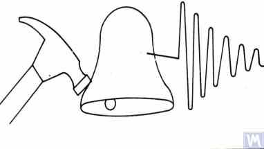
ਚਿੱਤਰ 3.3. ਕਿਸੇ ਵਸਤੂ ਦੀਆਂ ਕੁਦਰਤੀ ਫ੍ਰੀਕੁਐਂਸੀਆਂ ਨਿਰਧਾਰਿਤ ਕਰਨ ਲਈ ਵਰਤੇ ਜਾਂਦੇ ਇੰਪੈਕਟ ਐਕਸਾਈਟੇਸ਼ਨ ਦਾ ਚਿੱਤਰ
ਹੈਮਰ ਦਾ ਪੁੰਜ ਉਤੇਜਿਤ ਕੀਤੀ ਜਾ ਰਹੀ ਵਸਤੂ ਦੇ ਪੁੰਜ ਦੇ ਲਗਭਗ 10% ਹੋਣਾ ਚਾਹੀਦਾ ਹੈ। ਓਸਿਲੇਟਰੀ ਪ੍ਰਤੀਕਿਰਿਆ ਨੂੰ ਕੈਪਚਰ ਕਰਨ ਲਈ, ਜਾਂਚੀ ਜਾ ਰਹੀ ਵਸਤੂ ਉੱਤੇ ਇੱਕ ਵਾਈਬ੍ਰੇਸ਼ਨ ਸੈਂਸਰ ਲਗਾਇਆ ਜਾਣਾ ਚਾਹੀਦਾ ਹੈ, ਜਿਸਦਾ ਮਾਪਣ ਧੁਰਾ ਇੰਪੈਕਟ ਐਕਸਾਈਟੇਸ਼ਨ ਦੀ ਦਿਸ਼ਾ ਨਾਲ ਇਕਸਾਰ ਹੋਵੇ। ਕੁਝ ਮਾਮਲਿਆਂ ਵਿੱਚ, ਵਸਤੂ ਦੀ ਓਸਿਲੇਟਰੀ ਪ੍ਰਤੀਕਿਰਿਆ ਨੂੰ ਗ੍ਰਹਿਣ ਕਰਨ ਲਈ ਇੱਕ ਸ਼ੋਰ ਮਾਪਣ ਯੰਤਰ ਦਾ ਮਾਈਕ੍ਰੋਫੋਨ ਵੀ ਸੈਂਸਰ ਵਜੋਂ ਵਰਤਿਆ ਜਾ ਸਕਦਾ ਹੈ।
ਵਸਤੂ ਦੀਆਂ ਵਾਈਬ੍ਰੇਸ਼ਨਾਂ ਨੂੰ ਸੈਂਸਰ ਦੁਆਰਾ ਇੱਕ ਇਲੈਕਟ੍ਰੀਕਲ ਸਿਗਨਲ ਵਿੱਚ ਬਦਲਿਆ ਜਾਂਦਾ ਹੈ, ਜਿਸਨੂੰ ਫਿਰ ਇੱਕ ਮਾਪਣ ਯੰਤਰ, ਜਿਵੇਂ ਕਿ ਸਪੈਕਟ੍ਰਮ ਵਿਸ਼ਲੇਸ਼ਕ ਦੇ ਇਨਪੁਟ, ਨੂੰ ਭੇਜਿਆ ਜਾਂਦਾ ਹੈ। ਇਹ ਯੰਤਰ ਸਮਾਂ ਫੰਕਸ਼ਨ ਅਤੇ ਘਟਦੀ ਵਾਈਬ੍ਰੇਸ਼ਨਲ ਪ੍ਰਕਿਰਿਆ ਦੇ ਸਪੈਕਟ੍ਰਮ ਨੂੰ ਰਿਕਾਰਡ ਕਰਦਾ ਹੈ (ਚਿੱਤਰ 3.4 ਦੇਖੋ), ਜਿਸ ਦੇ ਵਿਸ਼ਲੇਸ਼ਣ ਨਾਲ ਵਸਤੂ ਦੀਆਂ ਕੁਦਰਤੀ ਵਾਈਬ੍ਰੇਸ਼ਨਾਂ ਦੀ ਬਾਰੰਬਾਰਤਾ (ਬਾਰੰਬਾਰਤਾਵਾਂ) ਨਿਰਧਾਰਿਤ ਕਰਨਾ ਸੰਭਵ ਹੁੰਦਾ ਹੈ।

ਚਿੱਤਰ 3.5. ਜਾਂਚੀ ਜਾ ਰਹੀ ਸੰਰਚਨਾ ਦੀਆਂ ਘਟਦੀਆਂ ਹੋਈਆਂ ਇੰਪੈਕਟ ਵਾਈਬ੍ਰੇਸ਼ਨਾਂ ਦੇ ਟਾਈਮ ਫੰਕਸ਼ਨ ਗ੍ਰਾਫ ਅਤੇ ਸਪੈਕਟ੍ਰਮ ਦਿਖਾਉਂਦਾ ਪ੍ਰੋਗਰਾਮ ਇੰਟਰਫੇਸ
ਚਿੱਤਰ 3.5 ਵਿੱਚ ਦਿੱਤੇ ਸਪੈਕਟ੍ਰਮ ਗ੍ਰਾਫ਼ (ਵਰਕ ਵਿੰਡੋ ਦੇ ਹੇਠਲੇ ਹਿੱਸੇ ਨੂੰ ਵੇਖੋ) ਦੇ ਵਿਸ਼ਲੇਸ਼ਣ ਤੋਂ ਪਤਾ ਚੱਲਦਾ ਹੈ ਕਿ ਜਾਂਚੇ ਗਏ ਢਾਂਚੇ ਦੀਆਂ ਕੁਦਰਤੀ ਥਿੜਕਣਾਂ ਦਾ ਮੁੱਖ ਕੰਪੋਨੈਂਟ, ਗ੍ਰਾਫ਼ ਦੇ abscissa ਧੁਰੇ ਦੇ ਸੰਦਰਭ ਵਿੱਚ ਨਿਰਧਾਰਤ ਕੀਤਾ ਗਿਆ, 9.5 Hz ਦੀ ਫ੍ਰੀਕੁਐਂਸੀ 'ਤੇ ਹੁੰਦਾ ਹੈ। ਇਹ ਵਿਧੀ Soft Bearing ਅਤੇ Hard Bearing ਦੋਵਾਂ ਬੈਲੇਂਸਿੰਗ ਮਸ਼ੀਨ ਸਪੋਰਟਾਂ ਦੀਆਂ ਕੁਦਰਤੀ ਥਿੜਕਣਾਂ ਦੇ ਅਧਿਐਨ ਲਈ ਸਿਫ਼ਾਰਸ਼ ਕੀਤੀ ਜਾ ਸਕਦੀ ਹੈ।
3.1.3.2. ਕੋਸਟਿੰਗ ਮੋਡ ਵਿੱਚ ਸਪੋਰਟਾਂ ਦੀਆਂ ਕੁਦਰਤੀ ਫ੍ਰੀਕੁਐਂਸੀਆਂ ਨਿਰਧਾਰਤ ਕਰਨਾ
ਕੁਝ ਮਾਮਲਿਆਂ ਵਿੱਚ, ਸਹਾਰਿਆਂ ਦੀ ਕੁਦਰਤੀ ਬਾਰੰਬਾਰਤਾ ਨੂੰ "ਕੋਸਟ" ਦੌਰਾਨ ਵਾਈਬ੍ਰੇਸ਼ਨ ਦੇ ਐਂਪਲੀਟਿਊਡ ਅਤੇ ਫੇਜ਼ ਨੂੰ ਚੱਕਰੀ ਢੰਗ ਨਾਲ ਮਾਪ ਕੇ ਨਿਰਧਾਰਿਤ ਕੀਤਾ ਜਾ ਸਕਦਾ ਹੈ। ਇਸ ਵਿਧੀ ਨੂੰ ਲਾਗੂ ਕਰਨ ਵੇਲੇ, ਜਾਂਚੀ ਜਾ ਰਹੀ ਮਸ਼ੀਨ 'ਤੇ ਲਗਾਏ ਗਏ ਰੋਟਰ ਨੂੰ ਪਹਿਲਾਂਵਾਂ ਇਸਦੀ ਵੱਧ ਤੋਂ ਵੱਧ ਘੁੰਮਣ ਗਤੀ ਤੱਕ ਤੇਜ਼ ਕੀਤਾ ਜਾਂਦਾ ਹੈ, ਜਿਸ ਤੋਂ ਬਾਅਦ ਇਸਦੀ ਡਰਾਈਵ ਬੰਦ ਕਰ ਦਿੱਤੀ ਜਾਂਦੀ ਹੈ, ਅਤੇ ਰੋਟਰ ਦੇ ਅਸੰਤੁਲਨ (imbalance) ਨਾਲ ਜੁੜੇ ਵਿਗਾੜਨ ਵਾਲੇ ਬਲ ਦੀ ਬਾਰੰਬਾਰਤਾ ਹੌਲੀ-ਹੌਲੀ ਵੱਧ ਤੋਂ ਵੱਧ ਤੋਂ ਰੁਕਣ ਦੇ ਬਿੰਦੂ ਤੱਕ ਘਟਦੀ ਹੈ।
ਇਸ ਸਥਿਤੀ ਵਿੱਚ, ਸਪੋਰਟਾਂ ਦੀਆਂ ਕੁਦਰਤੀ ਫ੍ਰੀਕੁਐਂਸੀਆਂ ਦੋ ਵਿਸ਼ੇਸ਼ਤਾਵਾਂ ਦੁਆਰਾ ਨਿਰਧਾਰਤ ਕੀਤੀਆਂ ਜਾ ਸਕਦੀਆਂ ਹਨ:
- ਰੈਜ਼ੋਨੈਂਸ ਖੇਤਰਾਂ ਵਿੱਚ ਦੇਖੇ ਗਏ ਥਿੜਕਣ ਆਯਾਮ ਵਿੱਚ ਸਥਾਨਕ ਛਾਲ ਦੁਆਰਾ;
- ਆਯਾਮ ਛਾਲ ਦੇ ਜ਼ੋਨ ਵਿੱਚ ਦੇਖੇ ਗਏ ਥਿੜਕਣ ਫੇਜ਼ ਵਿੱਚ ਤਿੱਖੀ ਤਬਦੀਲੀ (180° ਤੱਕ) ਦੁਆਰਾ।
"Balanset" ਸੀਰੀਜ਼ ਦੇ ਯੰਤਰਾਂ ਵਿੱਚ, ਵਸਤੂਆਂ ਦੀ ਕੁਦਰਤੀ ਬਾਰੰਬਾਰਤਾ ਨੂੰ "ਕੋਸਟ" ਦੌਰਾਨ ਪਛਾਣਨ ਲਈ "Vibrometer" ਮੋਡ ("Balanset 1") ਜਾਂ "Balancing. Monitoring" ਮੋਡ ("Balanset 2C" ਅਤੇ "Balanset 4") ਦੀ ਵਰਤੋਂ ਕੀਤੀ ਜਾ ਸਕਦੀ ਹੈ, ਜੋ ਰੋਟਰ ਦੀ ਘੁੰਮਣ ਬਾਰੰਬਾਰਤਾ 'ਤੇ ਵਾਈਬ੍ਰੇਸ਼ਨ ਦੇ ਐਂਪਲੀਟਿਊਡ ਅਤੇ ਫੇਜ਼ ਦੇ ਚੱਕਰੀ ਮਾਪਾਂ ਦੀ ਆਗਿਆ ਦਿੰਦੀ ਹੈ।
ਇਸ ਤੋਂ ਇਲਾਵਾ, "Balanset 1" ਸਾਫਟਵੇਅਰ ਵਿੱਚ ਵਾਧੂ ਤੌਰ 'ਤੇ ਇੱਕ ਵਿਸ਼ੇਸ਼ "Graphs. Coasting" ਮੋਡ ਸ਼ਾਮਲ ਹੈ, ਜੋ ਘੁੰਮਣ ਬਾਰੰਬਾਰਤਾ ਬਦਲਣ ਦੇ ਫੰਕਸ਼ਨ ਵਜੋਂ "ਕੋਸਟ" 'ਤੇ ਸਹਾਰੇ ਦੀ ਵਾਈਬ੍ਰੇਸ਼ਨ ਦੇ ਐਂਪਲੀਟਿਊਡ ਅਤੇ ਫੇਜ਼ ਵਿੱਚ ਬਦਲਾਵਾਂ ਦੇ ਗ੍ਰਾਫ਼ ਬਣਾਉਣ ਦੀ ਆਗਿਆ ਦਿੰਦਾ ਹੈ, ਜੋ ਰੈਜ਼ੋਨੈਂਸ ਦੀ ਪਛਾਣ ਕਰਨ ਦੀ ਪ੍ਰਕਿਰਿਆ ਨੂੰ ਕਾਫ਼ੀ ਸੌਖਾ ਬਣਾਉਂਦਾ ਹੈ।
ਇਹ ਧਿਆਨ ਦੇਣ ਯੋਗ ਹੈ ਕਿ, ਸਪੱਸ਼ਟ ਕਾਰਨਾਂ ਕਰਕੇ (ਸੈਕਸ਼ਨ 3.1.1 ਵੇਖੋ), ਕੋਸਟ 'ਤੇ ਸਪੋਰਟਾਂ ਦੀਆਂ ਕੁਦਰਤੀ ਫ੍ਰੀਕੁਐਂਸੀਆਂ ਦੀ ਪਛਾਣ ਕਰਨ ਦੀ ਵਿਧੀ ਸਿਰਫ਼ Soft Bearing ਬੈਲੇਂਸਿੰਗ ਮਸ਼ੀਨਾਂ ਦੇ ਅਧਿਐਨ ਦੇ ਮਾਮਲੇ ਵਿੱਚ ਹੀ ਵਰਤੀ ਜਾ ਸਕਦੀ ਹੈ, ਜਿੱਥੇ ਰੋਟਰ ਦੇ ਘੁੰਮਣ ਦੀਆਂ ਕਾਰਜਸ਼ੀਲ ਫ੍ਰੀਕੁਐਂਸੀਆਂ ਟ੍ਰਾਂਸਵਰਸ ਦਿਸ਼ਾ ਵਿੱਚ ਸਪੋਰਟਾਂ ਦੀਆਂ ਕੁਦਰਤੀ ਫ੍ਰੀਕੁਐਂਸੀਆਂ ਨਾਲੋਂ ਕਾਫ਼ੀ ਵੱਧ ਹੁੰਦੀਆਂ ਹਨ।
Hard Bearing ਮਸ਼ੀਨਾਂ ਦੇ ਮਾਮਲੇ ਵਿੱਚ, ਜਿੱਥੇ ਕੋਸਟ 'ਤੇ ਸਪੋਰਟਾਂ ਦੀਆਂ ਥਿੜਕਣਾਂ ਨੂੰ ਉਤੇਜਿਤ ਕਰਨ ਵਾਲੀਆਂ ਰੋਟਰ ਘੁੰਮਣ ਦੀਆਂ ਕਾਰਜਸ਼ੀਲ ਫ੍ਰੀਕੁਐਂਸੀਆਂ ਸਪੋਰਟਾਂ ਦੀਆਂ ਕੁਦਰਤੀ ਫ੍ਰੀਕੁਐਂਸੀਆਂ ਨਾਲੋਂ ਕਾਫ਼ੀ ਹੇਠਾਂ ਹੁੰਦੀਆਂ ਹਨ, ਇਸ ਵਿਧੀ ਦੀ ਵਰਤੋਂ ਵਿਹਾਰਕ ਤੌਰ 'ਤੇ ਅਸੰਭਵ ਹੈ।
3.1.4. ਬੈਲੇਂਸਿੰਗ ਮਸ਼ੀਨਾਂ ਲਈ ਸਪੋਰਟ ਡਿਜ਼ਾਈਨ ਕਰਨ ਅਤੇ ਬਣਾਉਣ ਲਈ ਵਿਹਾਰਕ ਸਿਫ਼ਾਰਸ਼ਾਂ
3.1.2. ਗਣਨਾਤਮਕ ਵਿਧੀਆਂ ਦੁਆਰਾ ਸਪੋਰਟਾਂ ਦੀਆਂ ਕੁਦਰਤੀ ਫ੍ਰੀਕੁਐਂਸੀਆਂ ਦੀ ਗਣਨਾ ਕਰਨਾ
ਉੱਪਰ ਦੱਸੀ ਗਈ ਗਣਨਾ ਯੋਜਨਾ ਦੀ ਵਰਤੋਂ ਕਰਦੇ ਹੋਏ ਸਪੋਰਟਾਂ ਦੀਆਂ ਕੁਦਰਤੀ ਫ੍ਰੀਕੁਐਂਸੀਆਂ ਦੀਆਂ ਗਣਨਾਵਾਂ ਦੋ ਦਿਸ਼ਾਵਾਂ ਵਿੱਚ ਕੀਤੀਆਂ ਜਾ ਸਕਦੀਆਂ ਹਨ:
- ਸਪੋਰਟਾਂ ਦੀ ਟ੍ਰਾਂਸਵਰਸ ਦਿਸ਼ਾ ਵਿੱਚ, ਜੋ ਰੋਟਰ ਅਸੰਤੁਲਨ ਦੀਆਂ ਸ਼ਕਤੀਆਂ ਕਾਰਨ ਹੋਣ ਵਾਲੀਆਂ ਉਹਨਾਂ ਦੀਆਂ ਥਿੜਕਣਾਂ ਨੂੰ ਮਾਪਣ ਦੀ ਦਿਸ਼ਾ ਨਾਲ ਮੇਲ ਖਾਂਦੀ ਹੈ;
- ਧੁਰੀ ਦਿਸ਼ਾ ਵਿੱਚ, ਜੋ ਮਸ਼ੀਨ ਦੇ ਸਪੋਰਟਾਂ 'ਤੇ ਲੱਗੇ ਬੈਲੇਂਸ ਕੀਤੇ ਜਾਣ ਵਾਲੇ ਰੋਟਰ ਦੇ ਘੁੰਮਣ ਧੁਰੇ ਨਾਲ ਮੇਲ ਖਾਂਦੀ ਹੈ।
ਲੰਬਕਾਰੀ ਦਿਸ਼ਾ ਵਿੱਚ ਸਹਾਰਿਆਂ ਦੀ ਕੁਦਰਤੀ ਬਾਰੰਬਾਰਤਾ ਦੀ ਗਣਨਾ ਕਰਨ ਲਈ ਇੱਕ ਵਧੇਰੇ ਗੁੰਝਲਦਾਰ ਗਣਨਾ ਤਕਨੀਕ ਦੀ ਵਰਤੋਂ ਦੀ ਲੋੜ ਹੁੰਦੀ ਹੈ, ਜਿਸ ਵਿੱਚ (ਸਹਾਰੇ ਅਤੇ ਸੰਤੁਲਿਤ ਕੀਤੇ ਜਾ ਰਹੇ ਰੋਟਰ ਦੇ ਪੈਰਾਮੀਟਰਾਂ ਤੋਂ ਇਲਾਵਾ) ਫਰੇਮ ਦੇ ਪੈਰਾਮੀਟਰਾਂ ਅਤੇ ਬੁਨਿਆਦ 'ਤੇ ਮਸ਼ੀਨ ਦੀ ਇੰਸਟਾਲੇਸ਼ਨ ਦੀਆਂ ਵਿਸ਼ੇਸ਼ਤਾਵਾਂ ਨੂੰ ਧਿਆਨ ਵਿੱਚ ਰੱਖਣਾ ਲਾਜ਼ਮੀ ਹੈ। ਇਸ ਵਿਧੀ ਬਾਰੇ ਇਸ ਪ੍ਰਕਾਸ਼ਨ ਵਿੱਚ ਚਰਚਾ ਨਹੀਂ ਕੀਤੀ ਗਈ ਹੈ। ਫਾਰਮੂਲਾ 3.1 ਦੇ ਵਿਸ਼ਲੇਸ਼ਣ ਨਾਲ ਕੁਝ ਸਧਾਰਨ ਸਿਫ਼ਾਰਸ਼ਾਂ ਮਿਲਦੀਆਂ ਹਨ ਜਿਨ੍ਹਾਂ ਨੂੰ ਮਸ਼ੀਨ ਡਿਜ਼ਾਈਨਰਾਂ ਨੂੰ ਆਪਣੀਆਂ ਵਿਹਾਰਕ ਗਤੀਵਿਧੀਆਂ ਵਿੱਚ ਧਿਆਨ ਵਿੱਚ ਰੱਖਣਾ ਚਾਹੀਦਾ ਹੈ। ਖਾਸ ਤੌਰ 'ਤੇ, ਕਿਸੇ ਸਹਾਰੇ ਦੀ ਕੁਦਰਤੀ ਬਾਰੰਬਾਰਤਾ ਨੂੰ ਇਸਦੀ ਕਠੋਰਤਾ (stiffness) ਅਤੇ/ਜਾਂ ਪੁੰਜ ਬਦਲ ਕੇ ਬਦਲਿਆ ਜਾ ਸਕਦਾ ਹੈ। ਕਠੋਰਤਾ ਵਧਾਉਣ ਨਾਲ ਸਹਾਰੇ ਦੀ ਕੁਦਰਤੀ ਬਾਰੰਬਾਰਤਾ ਵਧਦੀ ਹੈ, ਜਦਕਿ ਪੁੰਜ ਵਧਾਉਣ ਨਾਲ ਇਹ ਘਟਦੀ ਹੈ। ਇਹ ਬਦਲਾਵ ਗੈਰ-ਰੇਖਿਕ, ਵਰਗ-ਉਲਟ ਸਬੰਧ ਰੱਖਦੇ ਹਨ। ਉਦਾਹਰਨ ਲਈ, ਸਹਾਰੇ ਦੀ ਕਠੋਰਤਾ ਨੂੰ ਦੁੱਗਣਾ ਕਰਨ ਨਾਲ ਇਸਦੀ ਕੁਦਰਤੀ ਬਾਰੰਬਾਰਤਾ ਸਿਰਫ 1.4 ਗੁਣਾ ਵਧਦੀ ਹੈ। ਇਸੇ ਤਰ੍ਹਾਂ, ਸਹਾਰੇ ਦੇ ਚੱਲਣ ਵਾਲੇ ਹਿੱਸੇ ਦੇ ਪੁੰਜ ਨੂੰ ਦੁੱਗਣਾ ਕਰਨ ਨਾਲ ਇਸਦੀ ਕੁਦਰਤੀ ਬਾਰੰਬਾਰਤਾ ਸਿਰਫ 1.4 ਗੁਣਾ ਘਟਦੀ ਹੈ।
3.1.4.1. ਫਲੈਟ ਪਲੇਟ ਸਪ੍ਰਿੰਗਾਂ ਵਾਲੀਆਂ Soft Bearing ਮਸ਼ੀਨਾਂ
ਫਲੈਟ ਸਪ੍ਰਿੰਗਾਂ ਨਾਲ ਬਣੇ ਬੈਲੇਂਸਿੰਗ ਮਸ਼ੀਨ ਸਹਾਰਿਆਂ ਦੇ ਕਈ ਡਿਜ਼ਾਈਨ ਭਿੰਨਤਾਵਾਂ ਬਾਰੇ ਉੱਪਰ ਸੈਕਸ਼ਨ 2.1 ਵਿੱਚ ਚਰਚਾ ਕੀਤੀ ਗਈ ਹੈ ਅਤੇ ਚਿੱਤਰ 2.7 - 2.9 ਵਿੱਚ ਦਰਸਾਈ ਗਈ ਹੈ। ਸਾਡੀ ਜਾਣਕਾਰੀ ਅਨੁਸਾਰ, ਅਜਿਹੇ ਡਿਜ਼ਾਈਨ ਆਮ ਤੌਰ 'ਤੇ ਡਰਾਈਵ ਸ਼ਾਫਟਾਂ ਨੂੰ ਸੰਤੁਲਿਤ ਕਰਨ ਲਈ ਬਣਾਈਆਂ ਗਈਆਂ ਮਸ਼ੀਨਾਂ ਵਿੱਚ ਵਰਤੇ ਜਾਂਦੇ ਹਨ।
ਇੱਕ ਉਦਾਹਰਨ ਵਜੋਂ, ਆਓ ਸਾਡੇ ਇੱਕ ਗਾਹਕ (LLC "Rost-Service", ਸੇਂਟ ਪੀਟਰਸਬਰਗ) ਦੁਆਰਾ ਆਪਣੀ ਮਸ਼ੀਨ ਸਹਾਰਿਆਂ ਦੇ ਨਿਰਮਾਣ ਵਿੱਚ ਵਰਤੇ ਗਏ ਸਪ੍ਰਿੰਗ ਪੈਰਾਮੀਟਰਾਂ ਬਾਰੇ ਵਿਚਾਰ ਕਰੀਏ। ਇਹ ਮਸ਼ੀਨ 2, 3, ਅਤੇ 4-ਸਹਾਰੇ ਵਾਲੇ ਡਰਾਈਵ ਸ਼ਾਫਟਾਂ ਨੂੰ ਸੰਤੁਲਿਤ ਕਰਨ ਲਈ ਬਣਾਈ ਗਈ ਸੀ, ਜਿਨ੍ਹਾਂ ਦਾ ਪੁੰਜ 200 ਕਿਲੋਗ੍ਰਾਮ ਤੋਂ ਵੱਧ ਨਹੀਂ ਸੀ। ਗਾਹਕ ਦੁਆਰਾ ਚੁਣੇ ਗਏ, ਮਸ਼ੀਨ ਦੇ ਲੀਡਿੰਗ ਅਤੇ ਡ੍ਰਿਵਨ ਸਪਿੰਡਲਾਂ ਦੇ ਸਹਾਰਿਆਂ ਵਿੱਚ ਵਰਤੇ ਗਏ ਸਪ੍ਰਿੰਗਾਂ ਦੇ ਜਿਓਮੈਟ੍ਰਿਕ ਮਾਪ (ਉਚਾਈ * ਚੌੜਾਈ * ਮੋਟਾਈ) ਕ੍ਰਮਵਾਰ 300*200*3 ਮਿਲੀਮੀਟਰ ਸਨ।
"Balanset 4" ਮਸ਼ੀਨ ਦੀ ਸਟੈਂਡਰਡ ਮਾਪਣ ਪ੍ਰਣਾਲੀ ਦੀ ਵਰਤੋਂ ਕਰਦੇ ਹੋਏ ਇੰਪੈਕਟ ਐਕਸਾਈਟੇਸ਼ਨ ਵਿਧੀ ਦੁਆਰਾ ਪ੍ਰਯੋਗਾਤਮਕ ਤੌਰ 'ਤੇ ਨਿਰਧਾਰਿਤ ਕੀਤੀ ਗਈ, ਬਿਨਾਂ ਲੋਡ ਵਾਲੇ ਸਹਾਰੇ ਦੀ ਕੁਦਰਤੀ ਬਾਰੰਬਾਰਤਾ 11 - 12 Hz ਪਾਈ ਗਈ। ਸਹਾਰਿਆਂ ਦੀ ਵਾਈਬ੍ਰੇਸ਼ਨ ਦੀ ਅਜਿਹੀ ਕੁਦਰਤੀ ਬਾਰੰਬਾਰਤਾ 'ਤੇ, ਬੈਲੇਂਸਿੰਗ ਦੌਰਾਨ ਸੰਤੁਲਿਤ ਕੀਤੇ ਜਾ ਰਹੇ ਰੋਟਰ ਦੀ ਸਿਫ਼ਾਰਸ਼ ਕੀਤੀ ਘੁੰਮਣ ਬਾਰੰਬਾਰਤਾ 22-24 Hz (1320 – 1440 RPM) ਤੋਂ ਘੱਟ ਨਹੀਂ ਹੋਣੀ ਚਾਹੀਦੀ।
ਉਸੇ ਨਿਰਮਾਤਾ ਦੁਆਰਾ ਵਿਚਕਾਰਲੇ ਸਹਾਰਿਆਂ 'ਤੇ ਵਰਤੇ ਗਏ ਫਲੈਟ ਸਪ੍ਰਿੰਗਾਂ ਦੇ ਜਿਓਮੈਟ੍ਰਿਕ ਮਾਪ ਕ੍ਰਮਵਾਰ 200*200*3 ਮਿਲੀਮੀਟਰ ਸਨ। ਇਸ ਤੋਂ ਇਲਾਵਾ, ਜਿਵੇਂ ਕਿ ਅਧਿਐਨਾਂ ਨੇ ਦਿਖਾਇਆ, ਇਨ੍ਹਾਂ ਸਹਾਰਿਆਂ ਦੀ ਕੁਦਰਤੀ ਬਾਰੰਬਾਰਤਾ ਵੱਧ ਸੀ, ਜੋ 13-14 Hz ਤੱਕ ਪਹੁੰਚਦੀ ਸੀ।
ਟੈਸਟ ਦੇ ਨਤੀਜਿਆਂ ਦੇ ਆਧਾਰ 'ਤੇ, ਮਸ਼ੀਨ ਦੇ ਨਿਰਮਾਤਾਵਾਂ ਨੂੰ ਸਪਿੰਡਲ ਅਤੇ ਵਿਚਕਾਰਲੇ ਸਹਾਰਿਆਂ ਦੀ ਕੁਦਰਤੀ ਬਾਰੰਬਾਰਤਾ ਨੂੰ ਇਕਸਾਰ (ਬਰਾਬਰ) ਕਰਨ ਦੀ ਸਲਾਹ ਦਿੱਤੀ ਗਈ। ਇਸ ਨਾਲ ਬੈਲੇਂਸਿੰਗ ਦੌਰਾਨ ਡਰਾਈਵ ਸ਼ਾਫਟਾਂ ਦੀਆਂ ਸੰਚਾਲਨ ਘੁੰਮਣ ਬਾਰੰਬਾਰਤਾਵਾਂ ਦੀ ਰੇਂਜ ਦੀ ਚੋਣ ਸੌਖੀ ਹੋਵੇਗੀ ਅਤੇ ਸਹਾਰਿਆਂ ਦੇ ਰੈਜ਼ੋਨੈਂਟ ਵਾਈਬ੍ਰੇਸ਼ਨ ਦੇ ਖੇਤਰ ਵਿੱਚ ਦਾਖਲ ਹੋਣ ਕਾਰਨ ਮਾਪਣ ਪ੍ਰਣਾਲੀ ਦੀਆਂ ਰੀਡਿੰਗਾਂ ਦੀ ਸੰਭਾਵਿਤ ਅਸਥਿਰਤਾ ਤੋਂ ਬਚਿਆ ਜਾ ਸਕੇਗਾ।
ਫਲੈਟ ਸਪ੍ਰਿੰਗਾਂ 'ਤੇ ਸਪੋਰਟਾਂ ਦੀਆਂ ਥਿੜਕਣਾਂ ਦੀਆਂ ਕੁਦਰਤੀ ਫ੍ਰੀਕੁਐਂਸੀਆਂ ਨੂੰ ਐਡਜਸਟ ਕਰਨ ਦੀਆਂ ਵਿਧੀਆਂ ਸਪੱਸ਼ਟ ਹਨ। ਇਹ ਐਡਜਸਟਮੈਂਟ ਫਲੈਟ ਸਪ੍ਰਿੰਗਾਂ ਦੇ ਜਿਓਮੈਟ੍ਰਿਕ ਮਾਪ ਜਾਂ ਆਕਾਰ ਨੂੰ ਬਦਲ ਕੇ ਪ੍ਰਾਪਤ ਕੀਤੀ ਜਾ ਸਕਦੀ ਹੈ, ਜੋ, ਉਦਾਹਰਨ ਲਈ, ਲੰਬਵਤ ਜਾਂ ਟ੍ਰਾਂਸਵਰਸ ਸਲੌਟਾਂ ਦੀ ਮਿਲਿੰਗ ਕਰਕੇ ਪ੍ਰਾਪਤ ਕੀਤੀ ਜਾਂਦੀ ਹੈ ਜੋ ਉਹਨਾਂ ਦੀ ਕਠੋਰਤਾ ਨੂੰ ਘਟਾਉਂਦੀਆਂ ਹਨ।
ਜਿਵੇਂ ਕਿ ਪਹਿਲਾਂ ਦੱਸਿਆ ਗਿਆ ਹੈ, ਅਜਿਹੀ ਐਡਜਸਟਮੈਂਟ ਦੇ ਨਤੀਜਿਆਂ ਦੀ ਤਸਦੀਕ ਸੈਕਸ਼ਨ 3.1.3.1 ਅਤੇ 3.1.3.2 ਵਿੱਚ ਦੱਸੀਆਂ ਵਿਧੀਆਂ ਦੀ ਵਰਤੋਂ ਕਰਕੇ ਸਪੋਰਟਾਂ ਦੀਆਂ ਥਿੜਕਣਾਂ ਦੀਆਂ ਕੁਦਰਤੀ ਫ੍ਰੀਕੁਐਂਸੀਆਂ ਦੀ ਪਛਾਣ ਕਰਕੇ ਕੀਤੀ ਜਾ ਸਕਦੀ ਹੈ।
ਚਿੱਤਰ 3.6 A. Sinitsyn ਦੀਆਂ ਮਸ਼ੀਨਾਂ ਵਿੱਚੋਂ ਇੱਕ ਵਿੱਚ ਵਰਤੇ ਗਏ ਫਲੈਟ ਸਪ੍ਰਿੰਗਾਂ 'ਤੇ ਸਪੋਰਟ ਡਿਜ਼ਾਈਨ ਦਾ ਇੱਕ ਕਲਾਸਿਕ ਸੰਸਕਰਣ ਪੇਸ਼ ਕਰਦਾ ਹੈ। ਜਿਵੇਂ ਕਿ ਚਿੱਤਰ ਵਿੱਚ ਦਿਖਾਇਆ ਗਿਆ ਹੈ, ਸਪੋਰਟ ਵਿੱਚ ਹੇਠਾਂ ਦਿੱਤੇ ਕੰਪੋਨੈਂਟ ਸ਼ਾਮਲ ਹਨ:
- ਉੱਪਰੀ ਪਲੇਟ 1;
- ਦੋ ਫਲੈਟ ਸਪ੍ਰਿੰਗ 2 ਅਤੇ 3;
- ਹੇਠਲੀ ਪਲੇਟ 4;
- ਸਟਾਪ ਬਰੈਕਟ 5।
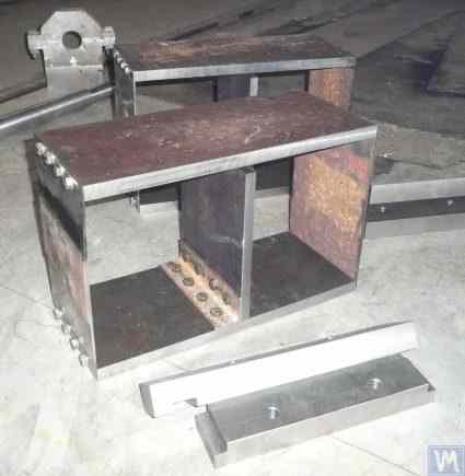
ਚਿੱਤਰ 3.6. ਫਲੈਟ ਸਪ੍ਰਿੰਗਾਂ 'ਤੇ ਸਪੋਰਟ ਦਾ ਡਿਜ਼ਾਈਨ ਵੇਰੀਏਸ਼ਨ
ਸਪੋਰਟ ਦੀ ਉੱਪਰੀ ਪਲੇਟ 1 ਦੀ ਵਰਤੋਂ ਸਪਿੰਡਲ ਜਾਂ ਇੱਕ ਵਿਚਕਾਰਲੇ ਬੇਅਰਿੰਗ ਨੂੰ ਲਗਾਉਣ ਲਈ ਕੀਤੀ ਜਾ ਸਕਦੀ ਹੈ। ਸਪੋਰਟ ਦੇ ਉਦੇਸ਼ 'ਤੇ ਨਿਰਭਰ ਕਰਦਿਆਂ, ਹੇਠਲੀ ਪਲੇਟ 4 ਨੂੰ ਮਸ਼ੀਨ ਦੀਆਂ ਗਾਈਡਾਂ ਨਾਲ ਸਖ਼ਤੀ ਨਾਲ ਜੋੜਿਆ ਜਾ ਸਕਦਾ ਹੈ ਜਾਂ ਚਲਣਯੋਗ ਸਲਾਈਡਾਂ 'ਤੇ ਲਗਾਇਆ ਜਾ ਸਕਦਾ ਹੈ, ਜਿਸ ਨਾਲ ਸਪੋਰਟ ਗਾਈਡਾਂ ਦੇ ਨਾਲ-ਨਾਲ ਹਿੱਲ ਸਕਦਾ ਹੈ। ਬਰੈਕਟ 5 ਦੀ ਵਰਤੋਂ ਸਪੋਰਟ ਲਈ ਇੱਕ ਲਾਕਿੰਗ ਮਕੈਨਿਜ਼ਮ ਲਗਾਉਣ ਲਈ ਕੀਤੀ ਜਾਂਦੀ ਹੈ, ਜਿਸ ਨਾਲ ਬੈਲੇਂਸ ਕੀਤੇ ਜਾ ਰਹੇ ਰੋਟਰ ਦੇ ਪ੍ਰਵੇਗ ਅਤੇ ਮੰਦੀ ਦੌਰਾਨ ਇਸਨੂੰ ਸੁਰੱਖਿਅਤ ਢੰਗ ਨਾਲ ਸਥਿਰ ਕੀਤਾ ਜਾ ਸਕੇ।
Soft Bearing ਮਸ਼ੀਨ ਸਹਾਰਿਆਂ ਲਈ ਫਲੈਟ ਸਪ੍ਰਿੰਗ ਲੀਫ-ਸਪ੍ਰਿੰਗ ਜਾਂ ਉੱਚ-ਗੁਣਵੱਤਾ ਵਾਲੇ ਐਲੋਏਡ ਸਟੀਲ ਤੋਂ ਬਣਾਏ ਜਾਣੇ ਚਾਹੀਦੇ ਹਨ। ਘੱਟ ਯੀਲਡ ਸਟ੍ਰੈਂਥ ਵਾਲੇ ਸਾਧਾਰਨ ਸਟ੍ਰਕਚਰਲ ਸਟੀਲਾਂ ਦੀ ਵਰਤੋਂ ਸਲਾਹਯੋਗ ਨਹੀਂ ਹੈ, ਕਿਉਂਕਿ ਸੰਚਾਲਨ ਦੌਰਾਨ ਸਟੈਟਿਕ ਅਤੇ ਡਾਇਨਾਮਿਕ ਲੋਡਾਂ ਹੇਠ ਉਨ੍ਹਾਂ ਵਿੱਚ ਰਹਿੰਦ-ਖੂੰਹਦ ਵਿਗਾੜ (residual deformation) ਪੈਦਾ ਹੋ ਸਕਦਾ ਹੈ, ਜਿਸ ਨਾਲ ਮਸ਼ੀਨ ਦੀ ਜਿਓਮੈਟ੍ਰਿਕ ਸ਼ੁੱਧਤਾ ਘਟ ਸਕਦੀ ਹੈ ਅਤੇ ਸਹਾਰੇ ਦੀ ਸਥਿਰਤਾ ਵੀ ਖਤਮ ਹੋ ਸਕਦੀ ਹੈ।
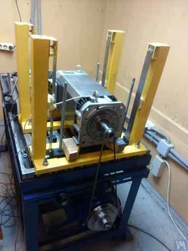
ਚਿੱਤਰ 3.7. A. Mokhov ਦੁਆਰਾ ਵਿਕਸਿਤ, ਇਲੈਕਟ੍ਰਿਕ ਮੋਟਰ ਰੋਟਰਾਂ ਦੇ ਬੈਲੇਂਸਿੰਗ ਲਈ ਮਸ਼ੀਨ, ਅਸੈਂਬਲਡ।
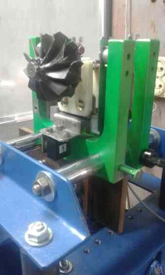
ਚਿੱਤਰ 3.8. G. Glazov (Bishkek) ਦੁਆਰਾ ਵਿਕਸਿਤ, ਟਰਬੋਪੰਪ ਰੋਟਰਾਂ ਦੇ ਬੈਲੇਂਸਿੰਗ ਲਈ ਮਸ਼ੀਨ
3.1.4.2. ਸਟ੍ਰਿਪ ਸਪ੍ਰਿੰਗਾਂ 'ਤੇ ਸਸਪੈਂਸ਼ਨ ਵਾਲੇ Soft Bearing ਮਸ਼ੀਨ ਸਪੋਰਟ
ਸਪੋਰਟ ਸਸਪੈਂਸ਼ਨਾਂ ਲਈ ਵਰਤੀਆਂ ਜਾਂਦੀਆਂ ਸਟ੍ਰਿਪ ਸਪ੍ਰਿੰਗਾਂ ਨੂੰ ਡਿਜ਼ਾਈਨ ਕਰਨ ਵੇਲੇ, ਸਪ੍ਰਿੰਗ ਸਟ੍ਰਿਪ ਦੀ ਮੋਟਾਈ ਅਤੇ ਚੌੜਾਈ ਦੀ ਚੋਣ ਵੱਲ ਧਿਆਨ ਦਿੱਤਾ ਜਾਣਾ ਚਾਹੀਦਾ ਹੈ, ਜੋ ਇੱਕ ਪਾਸੇ ਸਪੋਰਟ 'ਤੇ ਰੋਟਰ ਦੇ ਸਥਿਰ ਅਤੇ ਗਤੀਸ਼ੀਲ ਲੋਡ ਨੂੰ ਸਹਿਣ ਦੇ ਯੋਗ ਹੋਣੀ ਚਾਹੀਦੀ ਹੈ, ਅਤੇ ਦੂਜੇ ਪਾਸੇ, ਸਪੋਰਟ ਸਸਪੈਂਸ਼ਨ ਦੀਆਂ ਟੌਰਸ਼ਨਲ ਥਿੜਕਣਾਂ ਦੀ ਸੰਭਾਵਨਾ ਨੂੰ ਰੋਕਣਾ ਚਾਹੀਦਾ ਹੈ, ਜੋ ਧੁਰੀ ਰਨ-ਆਉਟ ਦੇ ਰੂਪ ਵਿੱਚ ਪ੍ਰਗਟ ਹੁੰਦੀ ਹੈ।
ਸਟ੍ਰਿਪ ਸਪ੍ਰਿੰਗ ਸਸਪੈਂਸ਼ਨਾਂ ਦੀ ਵਰਤੋਂ ਕਰਦੇ ਹੋਏ ਬੈਲੇਂਸਿੰਗ ਮਸ਼ੀਨਾਂ ਦੇ ਸਟ੍ਰਕਚਰਲ ਲਾਗੂਕਰਨ ਦੀਆਂ ਉਦਾਹਰਨਾਂ ਚਿੱਤਰ 2.1 - 2.5 (ਸੈਕਸ਼ਨ 2.1 ਦੇਖੋ) ਦੇ ਨਾਲ-ਨਾਲ ਇਸ ਸੈਕਸ਼ਨ ਦੇ ਚਿੱਤਰ 3.7 ਅਤੇ 3.8 ਵਿੱਚ ਦਰਸਾਈਆਂ ਗਈਆਂ ਹਨ।
3.1.4.4. ਮਸ਼ੀਨਾਂ ਲਈ Hard Bearing ਸਹਾਰੇ
ਜਿਵੇਂ ਕਿ ਸਾਡੇ ਗਾਹਕਾਂ ਨਾਲ ਵਿਆਪਕ ਤਜਰਬਾ ਦਰਸਾਉਂਦਾ ਹੈ, ਹਾਲ ਹੀ ਦੇ ਸਮੇਂ ਵਿੱਚ ਖੁਦ-ਨਿਰਮਾਤਾ ਬੈਲੇਂਸਰ ਬਣਾਉਣ ਵਾਲਿਆਂ ਦਾ ਇੱਕ ਮਹੱਤਵਪੂਰਨ ਹਿੱਸਾ ਕਠੋਰ ਸਹਾਰਿਆਂ ਵਾਲੀਆਂ Hard Bearing ਮਸ਼ੀਨਾਂ ਨੂੰ ਪਸੰਦ ਕਰਨ ਲੱਗਾ ਹੈ। ਸੈਕਸ਼ਨ 2.2 ਵਿੱਚ, ਚਿੱਤਰ 2.16 – 2.18 ਵਿੱਚ ਅਜਿਹੇ ਸਹਾਰਿਆਂ ਦੀ ਵਰਤੋਂ ਕਰਨ ਵਾਲੀਆਂ ਮਸ਼ੀਨਾਂ ਦੇ ਵੱਖ-ਵੱਖ ਸਟ੍ਰਕਚਰਲ ਡਿਜ਼ਾਈਨਾਂ ਦੀਆਂ ਤਸਵੀਰਾਂ ਦਰਸਾਈਆਂ ਗਈਆਂ ਹਨ। ਸਾਡੇ ਇੱਕ ਗਾਹਕ ਦੁਆਰਾ ਆਪਣੀ ਮਸ਼ੀਨ ਦੇ ਨਿਰਮਾਣ ਲਈ ਵਿਕਸਿਤ ਕੀਤੇ ਗਏ ਕਠੋਰ ਸਹਾਰੇ ਦਾ ਇੱਕ ਖਾਸ ਸਕੈਚ ਚਿੱਤਰ 3.10 ਵਿੱਚ ਪੇਸ਼ ਕੀਤਾ ਗਿਆ ਹੈ। ਇਹ ਸਹਾਰਾ P-ਆਕਾਰ ਦੇ ਖੰਡੇ (groove) ਵਾਲੀ ਇੱਕ ਫਲੈਟ ਸਟੀਲ ਪਲੇਟ ਤੋਂ ਬਣਿਆ ਹੈ, ਜੋ ਰਵਾਇਤੀ ਤੌਰ 'ਤੇ ਸਹਾਰੇ ਨੂੰ "ਕਠੋਰ" ਅਤੇ "ਲਚਕੀਲੇ" ਭਾਗਾਂ ਵਿੱਚ ਵੰਡਦਾ ਹੈ। ਅਸੰਤੁਲਨ ਬਲ ਦੇ ਪ੍ਰਭਾਵ ਹੇਠ, ਸਹਾਰੇ ਦਾ "ਲਚਕੀਲਾ" ਭਾਗ ਆਪਣੇ "ਕਠੋਰ" ਭਾਗ ਦੇ ਸਾਪੇਖਿਕ ਵਿਗੜ ਸਕਦਾ ਹੈ। ਇਸ ਵਿਗਾੜ ਦੀ ਮਾਤਰਾ, ਜੋ ਸਹਾਰੇ ਦੀ ਮੋਟਾਈ, ਖੰਡਿਆਂ ਦੀ ਡੂੰਘਾਈ, ਅਤੇ ਸਹਾਰੇ ਦੇ "ਲਚਕੀਲੇ" ਅਤੇ "ਕਠੋਰ" ਭਾਗਾਂ ਨੂੰ ਜੋੜਨ ਵਾਲੇ ਬ੍ਰਿਜ ਦੀ ਚੌੜਾਈ ਦੁਆਰਾ ਨਿਰਧਾਰਿਤ ਹੁੰਦੀ ਹੈ, ਨੂੰ ਮਸ਼ੀਨ ਦੀ ਮਾਪਣ ਪ੍ਰਣਾਲੀ ਦੇ ਢੁਕਵੇਂ ਸੈਂਸਰਾਂ ਦੀ ਵਰਤੋਂ ਕਰਕੇ ਮਾਪਿਆ ਜਾ ਸਕਦਾ ਹੈ। P-ਆਕਾਰ ਦੇ ਖੰਡੇ ਦੀ ਡੂੰਘਾਈ h, ਬ੍ਰਿਜ ਦੀ ਚੌੜਾਈ t, ਅਤੇ ਸਹਾਰੇ ਦੀ ਮੋਟਾਈ r (ਚਿੱਤਰ 3.10 ਦੇਖੋ) ਨੂੰ ਧਿਆਨ ਵਿੱਚ ਰੱਖਦੇ ਹੋਏ ਅਜਿਹੇ ਸਹਾਰਿਆਂ ਦੀ ਟ੍ਰਾਂਸਵਰਸ ਕਠੋਰਤਾ ਦੀ ਗਣਨਾ ਕਰਨ ਦੀ ਵਿਧੀ ਦੀ ਘਾਟ ਕਾਰਨ, ਇਹ ਡਿਜ਼ਾਈਨ ਪੈਰਾਮੀਟਰ ਆਮ ਤੌਰ 'ਤੇ ਨਿਰਮਾਤਾਵਾਂ ਦੁਆਰਾ ਪ੍ਰਯੋਗਾਤਮਕ ਤੌਰ 'ਤੇ ਨਿਰਧਾਰਿਤ ਕੀਤੇ ਜਾਂਦੇ ਹਨ।
300 - 500 ਕਿਲੋਗ੍ਰਾਮ ਤੋਂ ਵੱਧ ਪੁੰਜ ਨਾ ਹੋਣ ਵਾਲੇ ਸੰਤੁਲਿਤ ਰੋਟਰ ਵਾਲੀਆਂ ਮਸ਼ੀਨਾਂ ਲਈ, ਸਹਾਰੇ ਦੀ ਮੋਟਾਈ ਵਧਾ ਕੇ 30 – 40 ਮਿਲੀਮੀਟਰ ਕੀਤੀ ਜਾ ਸਕਦੀ ਹੈ, ਅਤੇ 1000 ਤੋਂ 3000 ਕਿਲੋਗ੍ਰਾਮ ਤੱਕ ਦੇ ਵੱਧ ਤੋਂ ਵੱਧ ਪੁੰਜ ਵਾਲੇ ਰੋਟਰਾਂ ਨੂੰ ਸੰਤੁਲਿਤ ਕਰਨ ਲਈ ਬਣਾਈਆਂ ਗਈਆਂ ਮਸ਼ੀਨਾਂ ਲਈ, ਸਹਾਰੇ ਦੀ ਮੋਟਾਈ 50 – 60 ਮਿਲੀਮੀਟਰ ਜਾਂ ਵੱਧ ਤੱਕ ਪਹੁੰਚ ਸਕਦੀ ਹੈ। ਜਿਵੇਂ ਕਿ ਉਪਰੋਕਤ ਸਹਾਰਿਆਂ ਦੀਆਂ ਡਾਇਨਾਮਿਕ ਵਿਸ਼ੇਸ਼ਤਾਵਾਂ ਦੇ ਵਿਸ਼ਲੇਸ਼ਣ ਤੋਂ ਪਤਾ ਲੱਗਦਾ ਹੈ, ਟ੍ਰਾਂਸਵਰਸ ਪਲੇਨ ("ਲਚਕੀਲੇ" ਅਤੇ "ਕਠੋਰ" ਭਾਗਾਂ ਦੇ ਸਾਪੇਖਿਕ ਵਿਗਾੜ ਦੇ ਮਾਪ ਦਾ ਪਲੇਨ) ਵਿੱਚ ਮਾਪੀਆਂ ਗਈਆਂ ਉਨ੍ਹਾਂ ਦੀਆਂ ਕੁਦਰਤੀ ਵਾਈਬ੍ਰੇਸ਼ਨ ਬਾਰੰਬਾਰਤਾਵਾਂ, ਆਮ ਤੌਰ 'ਤੇ 100 Hz ਜਾਂ ਵੱਧ ਤੋਂ ਵੱਧ ਹੁੰਦੀਆਂ ਹਨ। ਸੰਤੁਲਿਤ ਕੀਤੇ ਜਾ ਰਹੇ ਰੋਟਰ ਦੇ ਘੁੰਮਣ ਧੁਰੇ ਨਾਲ ਮੇਲ ਖਾਂਦੀ ਦਿਸ਼ਾ ਵਿੱਚ, ਫਰੰਟਲ ਪਲੇਨ ਵਿੱਚ ਮਾਪੇ ਗਏ Hard Bearing ਸਹਾਰਾ ਸਟੈਂਡਾਂ ਦੀਆਂ ਕੁਦਰਤੀ ਵਾਈਬ੍ਰੇਸ਼ਨ ਬਾਰੰਬਾਰਤਾਵਾਂ ਆਮ ਤੌਰ 'ਤੇ ਕਾਫ਼ੀ ਘੱਟ ਹੁੰਦੀਆਂ ਹਨ। ਅਤੇ ਇਹ ਉਹ ਬਾਰੰਬਾਰਤਾਵਾਂ ਹਨ ਜਿਨ੍ਹਾਂ ਨੂੰ ਮਸ਼ੀਨ 'ਤੇ ਸੰਤੁਲਿਤ ਕੀਤੇ ਜਾ ਰਹੇ ਘੁੰਮਣ ਵਾਲੇ ਰੋਟਰਾਂ ਦੀ ਸੰਚਾਲਨ ਬਾਰੰਬਾਰਤਾ ਰੇਂਜ ਦੀ ਉੱਪਰੀ ਸੀਮਾ ਨਿਰਧਾਰਿਤ ਕਰਦੇ ਸਮੇਂ ਮੁੱਖ ਤੌਰ 'ਤੇ ਧਿਆਨ ਵਿੱਚ ਰੱਖਿਆ ਜਾਣਾ ਚਾਹੀਦਾ ਹੈ।
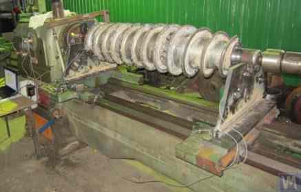
ਚਿੱਤਰ 3.26. Augers ਬੈਲੇਂਸਿੰਗ ਲਈ Hard Bearing ਮਸ਼ੀਨ ਬਣਾਉਣ ਲਈ ਵਰਤੇ ਗਏ ਲੇਥ ਬੈੱਡ ਦੀ ਵਰਤੋਂ ਦੀ ਉਦਾਹਰਨ।
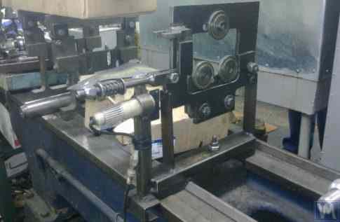
ਚਿੱਤਰ 3.27. ਸ਼ਾਫਟ ਬੈਲੇਂਸਿੰਗ ਲਈ Soft Bearing ਮਸ਼ੀਨ ਬਣਾਉਣ ਲਈ ਵਰਤੇ ਗਏ ਲੇਥ ਬੈੱਡ ਦੀ ਵਰਤੋਂ ਦੀ ਉਦਾਹਰਨ।
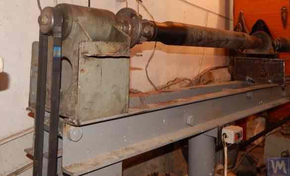
ਚਿੱਤਰ 3.28. ਚੈਨਲਾਂ ਤੋਂ ਅਸੈਂਬਲਡ ਬੈੱਡ ਬਣਾਉਣ ਦੀ ਉਦਾਹਰਨ
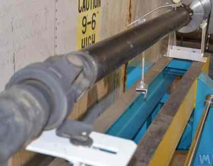
ਚਿੱਤਰ 3.29. ਚੈਨਲਾਂ ਤੋਂ ਵੈਲਡਿਡ ਬੈੱਡ ਬਣਾਉਣ ਦੀ ਉਦਾਹਰਨ
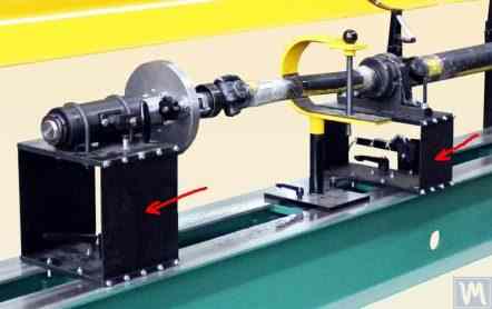
ਚਿੱਤਰ 3.30. ਚੈਨਲਾਂ ਤੋਂ ਵੈਲਡਿਡ ਬੈੱਡ ਦੇ ਨਿਰਮਾਣ ਦੀ ਉਦਾਹਰਨ
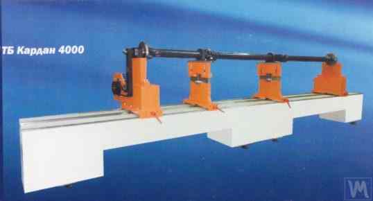
ਚਿੱਤਰ 3.31. ਪੌਲੀਮਰ ਕੰਕਰੀਟ ਤੋਂ ਬਣੇ ਬੈਲੇਂਸਿੰਗ ਮਸ਼ੀਨ ਬੈੱਡ ਦੀ ਉਦਾਹਰਨ
ਆਮ ਤੌਰ 'ਤੇ, ਅਜਿਹੇ ਬੈੱਡ ਬਣਾਉਂਦੇ ਸਮੇਂ, ਉਨ੍ਹਾਂ ਦੇ ਉੱਪਰਲੇ ਹਿੱਸੇ ਨੂੰ ਸਟੀਲ ਇਨਸਰਟਾਂ ਨਾਲ ਮਜ਼ਬੂਤ ਕੀਤਾ ਜਾਂਦਾ ਹੈ, ਜੋ ਗਾਈਡਾਂ ਵਜੋਂ ਵਰਤੇ ਜਾਂਦੇ ਹਨ ਜਿਨ੍ਹਾਂ 'ਤੇ ਬੈਲੇਂਸਿੰਗ ਮਸ਼ੀਨ ਦੇ ਸਹਾਰਾ ਸਟੈਂਡ ਟਿਕੇ ਹੁੰਦੇ ਹਨ। ਹਾਲ ਹੀ ਵਿੱਚ, ਵਾਈਬ੍ਰੇਸ਼ਨ-ਡੈਂਪਿੰਗ ਕੋਟਿੰਗਾਂ ਵਾਲੇ ਪੌਲੀਮਰ ਕੰਕਰੀਟ ਤੋਂ ਬਣੇ ਬੈੱਡ ਵਿਆਪਕ ਤੌਰ 'ਤੇ ਵਰਤੇ ਜਾਣ ਲੱਗੇ ਹਨ। ਬੈੱਡ ਬਣਾਉਣ ਦੀ ਇਹ ਤਕਨਾਲੋਜੀ ਔਨਲਾਈਨ ਚੰਗੀ ਤਰ੍ਹਾਂ ਦੱਸੀ ਗਈ ਹੈ ਅਤੇ ਖੁਦ-ਨਿਰਮਾਤਾਵਾਂ ਦੁਆਰਾ ਆਸਾਨੀ ਨਾਲ ਲਾਗੂ ਕੀਤੀ ਜਾ ਸਕਦੀ ਹੈ। ਨਿਰਮਾਣ ਦੀ ਸਾਪੇਖਿਕ ਸਾਦਗੀ ਅਤੇ ਘੱਟ ਲਾਗਤ ਕਾਰਨ, ਇਨ੍ਹਾਂ ਬੈੱਡਾਂ ਦੇ ਆਪਣੇ ਮੈਟਲ ਹਮਰੁਤਬਾ ਦੇ ਮੁਕਾਬਲੇ ਕਈ ਮੁੱਖ ਫਾਇਦੇ ਹਨ:
- ਥਿੜਕਣ ਓਸਿਲੇਸ਼ਨਾਂ ਲਈ ਵੱਧ ਡੈਂਪਿੰਗ ਗੁਣਾਂਕ;
- ਘੱਟ ਥਰਮਲ ਕੰਡਕਟੀਵਿਟੀ, ਜੋ ਬੈੱਡ ਦੀ ਘੱਟੋ-ਘੱਟ ਥਰਮਲ ਵਿਗਾੜ ਨੂੰ ਯਕੀਨੀ ਬਣਾਉਂਦੀ ਹੈ;
- ਵੱਧ ਖੋਰ ਪ੍ਰਤੀਰੋਧ;
- ਅੰਦਰੂਨੀ ਤਣਾਅ ਦੀ ਗੈਰਹਾਜ਼ਰੀ।
3.1.4.3. ਸਿਲੰਡ੍ਰੀਕਲ ਸਪ੍ਰਿੰਗਾਂ ਦੀ ਵਰਤੋਂ ਕਰਕੇ ਬਣਾਏ ਗਏ Soft Bearing ਮਸ਼ੀਨ ਸਪੋਰਟ
ਇੱਕ Soft Bearing ਬੈਲੇਂਸਿੰਗ ਮਸ਼ੀਨ ਦੀ ਇੱਕ ਉਦਾਹਰਨ, ਜਿਸ ਵਿੱਚ ਸਪੋਰਟਾਂ ਦੇ ਡਿਜ਼ਾਈਨ ਵਿੱਚ ਸਿਲੰਡ੍ਰੀਕਲ ਕੰਪ੍ਰੈਸ਼ਨ ਸਪ੍ਰਿੰਗਾਂ ਵਰਤੀਆਂ ਜਾਂਦੀਆਂ ਹਨ, ਚਿੱਤਰ 3.9 ਵਿੱਚ ਦਿਖਾਈ ਗਈ ਹੈ। ਇਸ ਡਿਜ਼ਾਈਨ ਹੱਲ ਦੀ ਮੁੱਖ ਕਮਜ਼ੋਰੀ ਅਗਲੀ ਅਤੇ ਪਿਛਲੀ ਸਪੋਰਟਾਂ ਵਿੱਚ ਸਪ੍ਰਿੰਗ ਵਿਗਾੜ ਦੀਆਂ ਵੱਖੋ-ਵੱਖ ਡਿਗਰੀਆਂ ਨਾਲ ਸੰਬੰਧਿਤ ਹੈ, ਜੋ ਉਦੋਂ ਵਾਪਰਦਾ ਹੈ ਜਦੋਂ ਅਸਮਿਤ ਰੋਟਰਾਂ ਦੇ ਬੈਲੇਂਸਿੰਗ ਦੌਰਾਨ ਸਪੋਰਟਾਂ 'ਤੇ ਲੋਡ ਅਸਮਾਨ ਹੁੰਦੇ ਹਨ। ਇਹ ਕੁਦਰਤੀ ਤੌਰ 'ਤੇ ਸਪੋਰਟਾਂ ਦੀ ਗ਼ਲਤ-ਸੰਰੇਖਣ ਅਤੇ ਲੰਬਵਤ ਸਮਤਲ ਵਿੱਚ ਰੋਟਰ ਧੁਰੇ ਦੇ ਟੇਢੇਪਣ ਵੱਲ ਲੈ ਜਾਂਦਾ ਹੈ। ਇਸ ਨੁਕਸ ਦੇ ਨਕਾਰਾਤਮਕ ਨਤੀਜਿਆਂ ਵਿੱਚੋਂ ਇੱਕ ਇਹ ਹੋ ਸਕਦਾ ਹੈ ਕਿ ਘੁੰਮਣ ਦੌਰਾਨ ਰੋਟਰ ਨੂੰ ਧੁਰੀ ਰੂਪ ਵਿੱਚ ਖਿਸਕਣ ਦਾ ਕਾਰਨ ਬਣਦੀਆਂ ਸ਼ਕਤੀਆਂ ਪੈਦਾ ਹੋਣ।
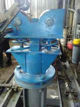
ਚਿੱਤਰ 3.9. ਸਿਲੰਡ੍ਰੀਕਲ ਸਪ੍ਰਿੰਗਾਂ ਦੀ ਵਰਤੋਂ ਕਰਦੇ ਹੋਏ ਬੈਲੇਂਸਿੰਗ ਮਸ਼ੀਨਾਂ ਲਈ Soft Bearing ਸਪੋਰਟ ਨਿਰਮਾਣ ਵੇਰੀਐਂਟ।
3.1.4.4. ਮਸ਼ੀਨਾਂ ਲਈ Hard Bearing ਸਹਾਰੇ
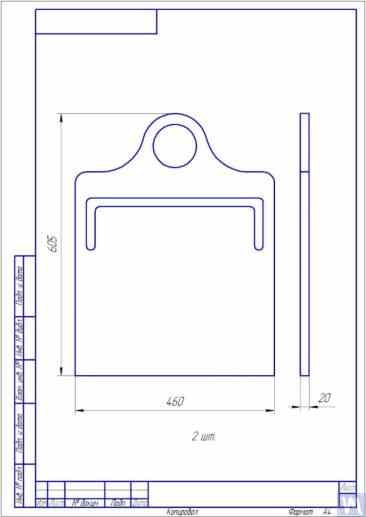
ਚਿੱਤਰ 3.10. ਬੈਲੇਂਸਿੰਗ ਮਸ਼ੀਨ ਲਈ Hard Bearing ਸਪੋਰਟ ਦਾ ਸਕੈਚ
ਸਾਡੇ ਗਾਹਕਾਂ ਦੀਆਂ ਖੁਦ ਦੀਆਂ ਮਸ਼ੀਨਾਂ ਲਈ ਬਣਾਏ ਗਏ ਅਜਿਹੇ ਸਹਾਰਿਆਂ ਦੇ ਵੱਖ-ਵੱਖ ਲਾਗੂਕਰਨਾਂ ਨੂੰ ਦਰਸਾਉਂਦੀਆਂ ਤਸਵੀਰਾਂ ਚਿੱਤਰ 3.11 ਅਤੇ 3.12 ਵਿੱਚ ਪੇਸ਼ ਕੀਤੀਆਂ ਗਈਆਂ ਹਨ। ਮਸ਼ੀਨ ਨਿਰਮਾਤਾ ਹੋਣ ਵਾਲੇ ਸਾਡੇ ਕਈ ਗਾਹਕਾਂ ਤੋਂ ਪ੍ਰਾਪਤ ਡੇਟਾ ਨੂੰ ਸੰਖੇਪ ਕਰਦੇ ਹੋਏ, ਵੱਖ-ਵੱਖ ਆਕਾਰ ਅਤੇ ਲੋਡ ਸਮਰੱਥਾ ਵਾਲੀਆਂ ਮਸ਼ੀਨਾਂ ਲਈ ਨਿਰਧਾਰਿਤ ਸਹਾਰੇ ਦੀ ਮੋਟਾਈ ਦੀਆਂ ਲੋੜਾਂ ਨੂੰ ਤਿਆਰ ਕੀਤਾ ਜਾ ਸਕਦਾ ਹੈ। ਉਦਾਹਰਨ ਲਈ, 0.1 ਤੋਂ 50-100 ਕਿਲੋਗ੍ਰਾਮ ਤੱਕ ਦੇ ਰੋਟਰਾਂ ਨੂੰ ਸੰਤੁਲਿਤ ਕਰਨ ਲਈ ਬਣਾਈਆਂ ਗਈਆਂ ਮਸ਼ੀਨਾਂ ਲਈ, ਸਹਾਰੇ ਦੀ ਮੋਟਾਈ 20 ਮਿਲੀਮੀਟਰ ਹੋ ਸਕਦੀ ਹੈ।
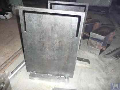
ਚਿੱਤਰ 3.11. A. Sinitsyn ਦੁਆਰਾ ਬਣਾਏ ਗਏ, ਬੈਲੇਂਸਿੰਗ ਮਸ਼ੀਨ ਲਈ Hard Bearing ਸਪੋਰਟ
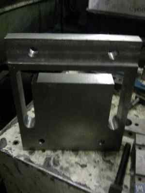
ਚਿੱਤਰ 3.12. D. Krasilnikov ਦੁਆਰਾ ਬਣਾਏ ਗਏ, ਬੈਲੇਂਸਿੰਗ ਮਸ਼ੀਨ ਲਈ Hard Bearing ਸਪੋਰਟ
300 - 500 ਕਿਲੋਗ੍ਰਾਮ ਤੋਂ ਵੱਧ ਪੁੰਜ ਨਾ ਹੋਣ ਵਾਲੇ ਸੰਤੁਲਿਤ ਰੋਟਰ ਵਾਲੀਆਂ ਮਸ਼ੀਨਾਂ ਲਈ, ਸਹਾਰੇ ਦੀ ਮੋਟਾਈ ਵਧਾ ਕੇ 30 – 40 ਮਿਲੀਮੀਟਰ ਕੀਤੀ ਜਾ ਸਕਦੀ ਹੈ, ਅਤੇ 1000 ਤੋਂ 3000 ਕਿਲੋਗ੍ਰਾਮ ਤੱਕ ਦੇ ਵੱਧ ਤੋਂ ਵੱਧ ਪੁੰਜ ਵਾਲੇ ਰੋਟਰਾਂ ਨੂੰ ਸੰਤੁਲਿਤ ਕਰਨ ਲਈ ਬਣਾਈਆਂ ਗਈਆਂ ਮਸ਼ੀਨਾਂ ਲਈ, ਸਹਾਰੇ ਦੀ ਮੋਟਾਈ 50 – 60 ਮਿਲੀਮੀਟਰ ਜਾਂ ਵੱਧ ਤੱਕ ਪਹੁੰਚ ਸਕਦੀ ਹੈ। ਜਿਵੇਂ ਕਿ ਉਪਰੋਕਤ ਸਹਾਰਿਆਂ ਦੀਆਂ ਡਾਇਨਾਮਿਕ ਵਿਸ਼ੇਸ਼ਤਾਵਾਂ ਦੇ ਵਿਸ਼ਲੇਸ਼ਣ ਤੋਂ ਪਤਾ ਲੱਗਦਾ ਹੈ, ਟ੍ਰਾਂਸਵਰਸ ਪਲੇਨ ("ਲਚਕੀਲੇ" ਅਤੇ "ਕਠੋਰ" ਭਾਗਾਂ ਦੇ ਸਾਪੇਖਿਕ ਵਿਗਾੜ ਦੇ ਮਾਪ ਦਾ ਪਲੇਨ) ਵਿੱਚ ਮਾਪੀਆਂ ਗਈਆਂ ਉਨ੍ਹਾਂ ਦੀਆਂ ਕੁਦਰਤੀ ਵਾਈਬ੍ਰੇਸ਼ਨ ਬਾਰੰਬਾਰਤਾਵਾਂ, ਆਮ ਤੌਰ 'ਤੇ 100 Hz ਜਾਂ ਵੱਧ ਤੋਂ ਵੱਧ ਹੁੰਦੀਆਂ ਹਨ। ਸੰਤੁਲਿਤ ਕੀਤੇ ਜਾ ਰਹੇ ਰੋਟਰ ਦੇ ਘੁੰਮਣ ਧੁਰੇ ਨਾਲ ਮੇਲ ਖਾਂਦੀ ਦਿਸ਼ਾ ਵਿੱਚ, ਫਰੰਟਲ ਪਲੇਨ ਵਿੱਚ ਮਾਪੇ ਗਏ Hard Bearing ਸਹਾਰਾ ਸਟੈਂਡਾਂ ਦੀਆਂ ਕੁਦਰਤੀ ਵਾਈਬ੍ਰੇਸ਼ਨ ਬਾਰੰਬਾਰਤਾਵਾਂ ਆਮ ਤੌਰ 'ਤੇ ਕਾਫ਼ੀ ਘੱਟ ਹੁੰਦੀਆਂ ਹਨ। ਅਤੇ ਇਹ ਉਹ ਬਾਰੰਬਾਰਤਾਵਾਂ ਹਨ ਜਿਨ੍ਹਾਂ ਨੂੰ ਮਸ਼ੀਨ 'ਤੇ ਸੰਤੁਲਿਤ ਕੀਤੇ ਜਾ ਰਹੇ ਘੁੰਮਣ ਵਾਲੇ ਰੋਟਰਾਂ ਦੀ ਸੰਚਾਲਨ ਬਾਰੰਬਾਰਤਾ ਰੇਂਜ ਦੀ ਉੱਪਰੀ ਸੀਮਾ ਨਿਰਧਾਰਿਤ ਕਰਦੇ ਸਮੇਂ ਮੁੱਖ ਤੌਰ 'ਤੇ ਧਿਆਨ ਵਿੱਚ ਰੱਖਿਆ ਜਾਣਾ ਚਾਹੀਦਾ ਹੈ। ਜਿਵੇਂ ਕਿ ਉੱਪਰ ਦੱਸਿਆ ਗਿਆ ਹੈ, ਇਨ੍ਹਾਂ ਬਾਰੰਬਾਰਤਾਵਾਂ ਦਾ ਨਿਰਧਾਰਨ ਸੈਕਸ਼ਨ 3.1 ਵਿੱਚ ਦੱਸੀ ਗਈ ਇੰਪੈਕਟ ਐਕਸਾਈਟੇਸ਼ਨ ਵਿਧੀ ਦੁਆਰਾ ਕੀਤਾ ਜਾ ਸਕਦਾ ਹੈ।
3.2. ਬੈਲੇਂਸਿੰਗ ਮਸ਼ੀਨਾਂ ਦੀਆਂ ਸਪੋਰਟਿੰਗ ਅਸੈਂਬਲੀਆਂ
3.2.1. ਸਪੋਰਟਿੰਗ ਅਸੈਂਬਲੀਆਂ ਦੀਆਂ ਮੁੱਖ ਕਿਸਮਾਂ
Hard Bearing ਅਤੇ Soft Bearing ਦੋਵਾਂ ਬੈਲੇਂਸਿੰਗ ਮਸ਼ੀਨਾਂ ਦੇ ਨਿਰਮਾਣ ਵਿੱਚ, ਸਪੋਰਟਾਂ 'ਤੇ ਬੈਲੇਂਸ ਕੀਤੇ ਜਾਣ ਵਾਲੇ ਰੋਟਰਾਂ ਨੂੰ ਲਗਾਉਣ ਅਤੇ ਘੁੰਮਾਉਣ ਲਈ ਵਰਤੀਆਂ ਜਾਂਦੀਆਂ, ਹੇਠ ਲਿਖੀਆਂ ਜਾਣੀਆਂ-ਪਛਾਣੀਆਂ ਕਿਸਮਾਂ ਦੀਆਂ ਸਪੋਰਟਿੰਗ ਅਸੈਂਬਲੀਆਂ ਦੀ ਸਿਫ਼ਾਰਸ਼ ਕੀਤੀ ਜਾ ਸਕਦੀ ਹੈ, ਜਿਸ ਵਿੱਚ ਸ਼ਾਮਲ ਹਨ:
- ਪ੍ਰਿਜ਼ਮੈਟਿਕ ਸਪੋਰਟਿੰਗ ਅਸੈਂਬਲੀਆਂ;
- ਘੁੰਮਣ ਵਾਲੇ ਰੋਲਰਾਂ ਵਾਲੀਆਂ ਸਪੋਰਟਿੰਗ ਅਸੈਂਬਲੀਆਂ;
- ਸਪਿੰਡਲ ਸਪੋਰਟਿੰਗ ਅਸੈਂਬਲੀਆਂ।
3.2.1.1. ਪ੍ਰਿਜ਼ਮੈਟਿਕ ਸਪੋਰਟਿੰਗ ਅਸੈਂਬਲੀਆਂ
ਇਹ ਅਸੈਂਬਲੀਆਂ, ਜਿਨ੍ਹਾਂ ਦੇ ਵੱਖ-ਵੱਖ ਡਿਜ਼ਾਈਨ ਵਿਕਲਪ ਹੁੰਦੇ ਹਨ, ਆਮ ਤੌਰ 'ਤੇ ਛੋਟੀਆਂ ਅਤੇ ਦਰਮਿਆਨੀਆਂ ਮਸ਼ੀਨਾਂ ਦੇ ਸਹਾਰਿਆਂ 'ਤੇ ਲਗਾਈਆਂ ਜਾਂਦੀਆਂ ਹਨ, ਜਿਨ੍ਹਾਂ 'ਤੇ 50 - 100 ਕਿਲੋਗ੍ਰਾਮ ਤੋਂ ਵੱਧ ਪੁੰਜ ਨਾ ਹੋਣ ਵਾਲੇ ਰੋਟਰਾਂ ਨੂੰ ਸੰਤੁਲਿਤ ਕੀਤਾ ਜਾ ਸਕਦਾ ਹੈ। ਇੱਕ ਪ੍ਰਿਜ਼ਮੈਟਿਕ ਸਪੋਰਟਿੰਗ ਅਸੈਂਬਲੀ ਦੇ ਸਭ ਤੋਂ ਸਰਲ ਸੰਸਕਰਣ ਦੀ ਇੱਕ ਉਦਾਹਰਨ ਚਿੱਤਰ 3.13 ਵਿੱਚ ਪੇਸ਼ ਕੀਤੀ ਗਈ ਹੈ। ਇਹ ਸਪੋਰਟਿੰਗ ਅਸੈਂਬਲੀ ਸਟੀਲ ਦੀ ਬਣੀ ਹੈ ਅਤੇ ਇੱਕ ਟਰਬਾਈਨ ਬੈਲੇਂਸਿੰਗ ਮਸ਼ੀਨ 'ਤੇ ਵਰਤੀ ਜਾਂਦੀ ਹੈ। ਛੋਟੀਆਂ ਅਤੇ ਦਰਮਿਆਨੀਆਂ ਬੈਲੇਂਸਿੰਗ ਮਸ਼ੀਨਾਂ ਦੇ ਕਈ ਨਿਰਮਾਤਾ, ਪ੍ਰਿਜ਼ਮੈਟਿਕ ਸਪੋਰਟਿੰਗ ਅਸੈਂਬਲੀਆਂ ਬਣਾਉਂਦੇ ਸਮੇਂ, ਗੈਰ-ਮੈਟਲਿਕ ਸਮੱਗਰੀਆਂ (ਡਾਈਇਲੈਕਟ੍ਰਿਕਸ), ਜਿਵੇਂ ਕਿ ਟੈਕਸਟੋਲਾਈਟ, ਫਲੂਓਰੋਪਲਾਸਟਿਕ, ਕੈਪ੍ਰੋਲੋਨ, ਆਦਿ ਦੀ ਵਰਤੋਂ ਕਰਨਾ ਪਸੰਦ ਕਰਦੇ ਹਨ।
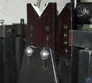
3.13. ਆਟੋਮੋਬਾਈਲ ਟਰਬਾਈਨਾਂ ਲਈ ਬੈਲੇਂਸਿੰਗ ਮਸ਼ੀਨ 'ਤੇ ਵਰਤੇ ਜਾਂਦੇ ਪ੍ਰਿਜ਼ਮੈਟਿਕ ਸਪੋਰਟਿੰਗ ਅਸੈਂਬਲੀ ਦਾ ਐਗਜ਼ੀਕਿਊਸ਼ਨ ਵੇਰੀਐਂਟ
ਇਸੇ ਤਰ੍ਹਾਂ ਦੀਆਂ ਸਪੋਰਟਿੰਗ ਅਸੈਂਬਲੀਆਂ (ਉੱਪਰ ਚਿੱਤਰ 3.8 ਦੇਖੋ) ਨੂੰ, ਉਦਾਹਰਨ ਲਈ, G. Glazov ਨੇ ਆਪਣੀ ਮਸ਼ੀਨ ਵਿੱਚ ਲਾਗੂ ਕੀਤਾ ਹੈ, ਜੋ ਆਟੋਮੋਬਾਈਲ ਟਰਬਾਈਨਾਂ ਨੂੰ ਸੰਤੁਲਿਤ ਕਰਨ ਲਈ ਵੀ ਬਣਾਈ ਗਈ ਹੈ। ਫਲੂਓਰੋਪਲਾਸਟਿਕ ਤੋਂ ਬਣੀ ਪ੍ਰਿਜ਼ਮੈਟਿਕ ਸਪੋਰਟਿੰਗ ਅਸੈਂਬਲੀ ਦਾ ਮੌਲਿਕ ਤਕਨੀਕੀ ਹੱਲ (ਚਿੱਤਰ 3.14 ਦੇਖੋ) LLC "Technobalance" ਦੁਆਰਾ ਪੇਸ਼ ਕੀਤਾ ਗਿਆ ਹੈ।
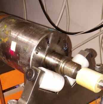
ਚਿੱਤਰ 3.14. LLC "Technobalance" ਦੁਆਰਾ ਪ੍ਰਿਜ਼ਮੈਟਿਕ ਸਪੋਰਟ ਅਸੈਂਬਲੀ
ਇਹ ਖਾਸ ਸਪੋਰਟਿੰਗ ਅਸੈਂਬਲੀ ਦੋ ਸਿਲੰਡਰਿਕਲ ਸਲੀਵਾਂ 1 ਅਤੇ 2 ਦੀ ਵਰਤੋਂ ਕਰਕੇ ਬਣਾਈ ਗਈ ਹੈ, ਜੋ ਇੱਕ ਦੂਜੇ ਨਾਲ ਕੋਣ 'ਤੇ ਲਗਾਈਆਂ ਗਈਆਂ ਹਨ ਅਤੇ ਸਪੋਰਟਿੰਗ ਧੁਰਿਆਂ 'ਤੇ ਸਥਿਰ ਕੀਤੀਆਂ ਗਈਆਂ ਹਨ। ਸੰਤੁਲਿਤ ਕੀਤਾ ਜਾ ਰਿਹਾ ਰੋਟਰ ਸਿਲੰਡਰਾਂ ਦੀਆਂ ਜਨਰੇਟਿੰਗ ਲਾਈਨਾਂ ਦੇ ਨਾਲ ਸਲੀਵਾਂ ਦੀਆਂ ਸਤਹਾਂ ਨੂੰ ਛੂਹਦਾ ਹੈ, ਜੋ ਰੋਟਰ ਸ਼ਾਫਟ ਅਤੇ ਸਹਾਰੇ ਵਿਚਕਾਰ ਸੰਪਰਕ ਖੇਤਰ ਨੂੰ ਘੱਟ ਤੋਂ ਘੱਟ ਕਰਦਾ ਹੈ, ਨਤੀਜੇ ਵਜੋਂ ਸਹਾਰੇ ਵਿੱਚ ਘ੍ਰਿਸ਼ਣ ਬਲ (friction force) ਘਟਦਾ ਹੈ। ਜੇ ਲੋੜ ਹੋਵੇ, ਰੋਟਰ ਸ਼ਾਫਟ ਨਾਲ ਸੰਪਰਕ ਦੇ ਖੇਤਰ ਵਿੱਚ ਸਹਾਰੇ ਦੀ ਸਤਹ ਦੇ ਘਿਸਣ ਜਾਂ ਨੁਕਸਾਨ ਦੀ ਸਥਿਤੀ ਵਿੱਚ, ਸਲੀਵ ਨੂੰ ਇਸਦੇ ਧੁਰੇ ਦੁਆਲੇ ਕੁਝ ਕੋਣ ਨਾਲ ਘੁਮਾ ਕੇ ਘਿਸਾਵਟ ਦੀ ਭਰਪਾਈ ਦੀ ਸੰਭਾਵਨਾ ਪ੍ਰਦਾਨ ਕੀਤੀ ਜਾਂਦੀ ਹੈ। ਇਹ ਧਿਆਨ ਦੇਣ ਯੋਗ ਹੈ ਕਿ ਗੈਰ-ਮੈਟਲਿਕ ਸਮੱਗਰੀਆਂ ਤੋਂ ਬਣੀਆਂ ਸਪੋਰਟਿੰਗ ਅਸੈਂਬਲੀਆਂ ਦੀ ਵਰਤੋਂ ਕਰਦੇ ਸਮੇਂ, ਸੰਤੁਲਿਤ ਕੀਤੇ ਜਾ ਰਹੇ ਰੋਟਰ ਨੂੰ ਮਸ਼ੀਨ ਬਾਡੀ ਨਾਲ ਗਰਾਊਂਡ ਕਰਨ ਦੀ ਸਟ੍ਰਕਚਰਲ ਸੰਭਾਵਨਾ ਪ੍ਰਦਾਨ ਕਰਨਾ ਜ਼ਰੂਰੀ ਹੈ, ਜੋ ਸੰਚਾਲਨ ਦੌਰਾਨ ਸ਼ਕਤੀਸ਼ਾਲੀ ਸਟੈਟਿਕ ਬਿਜਲੀ ਚਾਰਜਾਂ ਦੇ ਵਾਪਰਨ ਦੇ ਖਤਰੇ ਨੂੰ ਖਤਮ ਕਰਦਾ ਹੈ। ਇਹ, ਪਹਿਲਾਂਵਾਂ, ਬਿਜਲਈ ਦਖਲਅੰਦਾਜ਼ੀ ਅਤੇ ਗੜਬੜੀਆਂ ਨੂੰ ਘਟਾਉਣ ਵਿੱਚ ਮਦਦ ਕਰਦਾ ਹੈ ਜੋ ਮਸ਼ੀਨ ਦੀ ਮਾਪਣ ਪ੍ਰਣਾਲੀ ਦੀ ਕਾਰਗੁਜ਼ਾਰੀ ਨੂੰ ਪ੍ਰਭਾਵਿਤ ਕਰ ਸਕਦੀਆਂ ਹਨ, ਅਤੇ ਦੂਜਾ, ਸਟੈਟਿਕ ਬਿਜਲੀ ਦੀ ਕਾਰਵਾਈ ਨਾਲ ਸਟਾਫ ਦੇ ਪ੍ਰਭਾਵਿਤ ਹੋਣ ਦੇ ਖਤਰੇ ਨੂੰ ਖਤਮ ਕਰਦਾ ਹੈ।
3.2.1.2. ਰੋਲਰ ਸਪੋਰਟਿੰਗ ਅਸੈਂਬਲੀਆਂ
ਇਹ ਅਸੈਂਬਲੀਆਂ ਆਮ ਤੌਰ 'ਤੇ 50 ਕਿਲੋਗ੍ਰਾਮ ਤੋਂ ਵੱਧ ਪੁੰਜ ਵਾਲੇ ਰੋਟਰਾਂ ਨੂੰ ਸੰਤੁਲਿਤ ਕਰਨ ਲਈ ਬਣਾਈਆਂ ਗਈਆਂ ਮਸ਼ੀਨਾਂ ਦੇ ਸਹਾਰਿਆਂ 'ਤੇ ਲਗਾਈਆਂ ਜਾਂਦੀਆਂ ਹਨ। ਇਨ੍ਹਾਂ ਦੀ ਵਰਤੋਂ ਪ੍ਰਿਜ਼ਮੈਟਿਕ ਸਹਾਰਿਆਂ ਦੇ ਮੁਕਾਬਲੇ ਸਹਾਰਿਆਂ ਵਿੱਚ ਘ੍ਰਿਸ਼ਣ ਬਲਾਂ ਨੂੰ ਕਾਫ਼ੀ ਘਟਾਉਂਦੀ ਹੈ, ਜਿਸ ਨਾਲ ਸੰਤੁਲਿਤ ਕੀਤੇ ਜਾ ਰਹੇ ਰੋਟਰ ਦੀ ਘੁੰਮਣ ਸੌਖੀ ਹੁੰਦੀ ਹੈ। ਉਦਾਹਰਨ ਵਜੋਂ, ਚਿੱਤਰ 3.15 ਇੱਕ ਸਪੋਰਟਿੰਗ ਅਸੈਂਬਲੀ ਦਾ ਡਿਜ਼ਾਈਨ ਵੇਰੀਐਂਟ ਦਿਖਾਉਂਦਾ ਹੈ ਜਿੱਥੇ ਉਤਪਾਦ ਦੀ ਸਥਿਤੀ ਨਿਰਧਾਰਣ ਲਈ ਰੋਲਰਾਂ ਦੀ ਵਰਤੋਂ ਕੀਤੀ ਜਾਂਦੀ ਹੈ। ਇਸ ਡਿਜ਼ਾਈਨ ਵਿੱਚ, ਸਟੈਂਡਰਡ ਰੋਲਿੰਗ ਬੇਅਰਿੰਗਾਂ ਨੂੰ ਰੋਲਰ 1 ਅਤੇ 2 ਵਜੋਂ ਵਰਤਿਆ ਜਾਂਦਾ ਹੈ, ਜਿਨ੍ਹਾਂ ਦੀਆਂ ਬਾਹਰੀ ਰਿੰਗਾਂ ਮਸ਼ੀਨ ਦੇ ਸਹਾਰੇ 3 ਦੀ ਬਾਡੀ ਵਿੱਚ ਸਥਿਰ ਧੁਰਿਆਂ 'ਤੇ ਘੁੰਮਦੀਆਂ ਹਨ। ਚਿੱਤਰ 3.16 ਖੁਦ-ਨਿਰਮਾਤਾ ਬੈਲੇਂਸਿੰਗ ਮਸ਼ੀਨ ਨਿਰਮਾਤਾਵਾਂ ਵਿੱਚੋਂ ਇੱਕ ਦੁਆਰਾ ਆਪਣੇ ਪ੍ਰੋਜੈਕਟ ਵਿੱਚ ਲਾਗੂ ਕੀਤੇ ਗਏ ਰੋਲਰ ਸਪੋਰਟਿੰਗ ਅਸੈਂਬਲੀ ਦੇ ਇੱਕ ਵਧੇਰੇ ਗੁੰਝਲਦਾਰ ਡਿਜ਼ਾਈਨ ਦਾ ਸਕੈਚ ਦਰਸਾਉਂਦਾ ਹੈ। ਜਿਵੇਂ ਕਿ ਡਰਾਇੰਗ ਤੋਂ ਦੇਖਿਆ ਜਾ ਸਕਦਾ ਹੈ, ਰੋਲਰ (ਅਤੇ ਨਤੀਜੇ ਵਜੋਂ ਸਮੁੱਚੀ ਸਪੋਰਟਿੰਗ ਅਸੈਂਬਲੀ) ਦੀ ਲੋਡ ਸਮਰੱਥਾ ਵਧਾਉਣ ਲਈ, ਰੋਲਰ ਬਾਡੀ 3 ਵਿੱਚ ਰੋਲਿੰਗ ਬੇਅਰਿੰਗਾਂ 1 ਅਤੇ 2 ਦਾ ਇੱਕ ਜੋੜਾ ਲਗਾਇਆ ਜਾਂਦਾ ਹੈ। ਇਸ ਡਿਜ਼ਾਈਨ ਦਾ ਵਿਹਾਰਕ ਲਾਗੂਕਰਨ, ਇਸਦੇ ਸਾਰੇ ਸਪੱਸ਼ਟ ਫਾਇਦਿਆਂ ਦੇ ਬਾਵਜੂਦ, ਇੱਕ ਕਾਫ਼ੀ ਗੁੰਝਲਦਾਰ ਕਾਰਜ ਜਾਪਦਾ ਹੈ, ਜੋ ਰੋਲਰ ਬਾਡੀ 3 ਦੇ ਸੁਤੰਤਰ ਨਿਰਮਾਣ ਦੀ ਲੋੜ ਨਾਲ ਜੁੜਿਆ ਹੋਇਆ ਹੈ, ਜਿਸ ਲਈ ਸਮੱਗਰੀ ਦੀ ਜਿਓਮੈਟ੍ਰਿਕ ਸ਼ੁੱਧਤਾ ਅਤੇ ਮਕੈਨੀਕਲ ਵਿਸ਼ੇਸ਼ਤਾਵਾਂ ਲਈ ਬਹੁਤ ਉੱਚੀਆਂ ਲੋੜਾਂ ਲਗਾਈਆਂ ਜਾਂਦੀਆਂ ਹਨ।
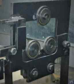
ਚਿੱਤਰ 3.15. ਰੋਲਰ ਸਪੋਰਟਿੰਗ ਅਸੈਂਬਲੀ ਡਿਜ਼ਾਈਨ ਦੀ ਉਦਾਹਰਨ
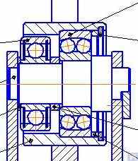
ਚਿੱਤਰ 3.16. ਦੋ ਰੋਲਿੰਗ ਬੇਅਰਿੰਗਾਂ ਵਾਲੀ ਰੋਲਰ ਸਪੋਰਟਿੰਗ ਅਸੈਂਬਲੀ ਡਿਜ਼ਾਈਨ ਦੀ ਉਦਾਹਰਨ
ਚਿੱਤਰ 3.17 LLC "Technobalance" ਦੇ ਮਾਹਿਰਾਂ ਦੁਆਰਾ ਵਿਕਸਿਤ ਕੀਤੀ ਗਈ ਇੱਕ ਸਵੈ-ਸੰਰੇਖਿਤ (self-aligning) ਰੋਲਰ ਸਪੋਰਟਿੰਗ ਅਸੈਂਬਲੀ ਦਾ ਡਿਜ਼ਾਈਨ ਵੇਰੀਐਂਟ ਪੇਸ਼ ਕਰਦਾ ਹੈ। ਇਸ ਡਿਜ਼ਾਈਨ ਵਿੱਚ, ਰੋਲਰਾਂ ਦੀ ਸਵੈ-ਸੰਰੇਖਿਤ ਸਮਰੱਥਾ ਉਨ੍ਹਾਂ ਨੂੰ ਦੋ ਵਾਧੂ ਸੁਤੰਤਰਤਾ ਦੀਆਂ ਡਿਗਰੀਆਂ ਪ੍ਰਦਾਨ ਕਰਕੇ ਪ੍ਰਾਪਤ ਕੀਤੀ ਜਾਂਦੀ ਹੈ, ਜੋ ਰੋਲਰਾਂ ਨੂੰ X ਅਤੇ Y ਧੁਰਿਆਂ ਦੁਆਲੇ ਛੋਟੀਆਂ ਕੋਣੀ ਹਰਕਤਾਂ ਕਰਨ ਦੀ ਆਗਿਆ ਦਿੰਦੀ ਹੈ। ਅਜਿਹੀਆਂ ਸਪੋਰਟਿੰਗ ਅਸੈਂਬਲੀਆਂ, ਜੋ ਸੰਤੁਲਿਤ ਕੀਤੇ ਜਾ ਰਹੇ ਰੋਟਰਾਂ ਦੀ ਸਥਾਪਨਾ ਵਿੱਚ ਉੱਚ ਸ਼ੁੱਧਤਾ ਯਕੀਨੀ ਬਣਾਉਂਦੀਆਂ ਹਨ, ਆਮ ਤੌਰ 'ਤੇ ਭਾਰੀ ਬੈਲੇਂਸਿੰਗ ਮਸ਼ੀਨਾਂ ਦੇ ਸਹਾਰਿਆਂ 'ਤੇ ਵਰਤੋਂ ਲਈ ਸਿਫ਼ਾਰਸ਼ ਕੀਤੀਆਂ ਜਾਂਦੀਆਂ ਹਨ।
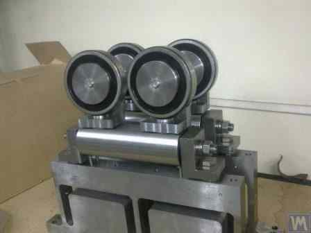
ਚਿੱਤਰ 3.17. ਸੈਲਫ-ਅਲਾਈਨਿੰਗ ਰੋਲਰ ਸਪੋਰਟਿੰਗ ਅਸੈਂਬਲੀ ਡਿਜ਼ਾਈਨ ਦੀ ਉਦਾਹਰਨ
ਜਿਵੇਂ ਕਿ ਪਹਿਲਾਂ ਦੱਸਿਆ ਗਿਆ ਹੈ, ਰੋਲਰ ਸਪੋਰਟ ਅਸੈਂਬਲੀਆਂ ਵਿੱਚ ਆਮ ਤੌਰ 'ਤੇ ਸਟੀਕ ਨਿਰਮਾਣ ਅਤੇ ਕਠੋਰਤਾ ਲਈ ਕਾਫ਼ੀ ਉੱਚ ਲੋੜਾਂ ਹੁੰਦੀਆਂ ਹਨ। ਖਾਸ ਤੌਰ 'ਤੇ, ਰੋਲਰਾਂ ਦੇ ਰੇਡੀਏਲ ਰਨਆਊਟ ਲਈ ਨਿਰਧਾਰਤ ਟਾਲਰੈਂਸ 3-5 ਮਾਈਕਰੋਨ ਤੋਂ ਵੱਧ ਨਹੀਂ ਹੋਣੀ ਚਾਹੀਦੀ।
ਅਭਿਆਸ ਵਿੱਚ, ਇਹ ਹਮੇਸ਼ਾ ਪ੍ਰਸਿੱਧ ਨਿਰਮਾਤਾਵਾਂ ਦੁਆਰਾ ਵੀ ਪ੍ਰਾਪਤ ਨਹੀਂ ਕੀਤਾ ਜਾਂਦਾ। ਉਦਾਹਰਣ ਵਜੋਂ, ਲੇਖਕ ਦੁਆਰਾ ਬੈਲੰਸਿੰਗ ਮਸ਼ੀਨ ਮਾਡਲ H8V, ਬ੍ਰਾਂਡ "K. Shenk" ਲਈ ਸਪੇਅਰ ਪਾਰਟਸ ਵਜੋਂ ਖਰੀਦੀ ਗਈ ਨਵੀਂ ਰੋਲਰ ਸਪੋਰਟ ਅਸੈਂਬਲੀਆਂ ਦੇ ਸੈੱਟ ਦੇ ਰੇਡੀਅਲ ਰਨਆਊਟ ਦੀ ਜਾਂਚ ਦੌਰਾਨ, ਉਹਨਾਂ ਦੇ ਰੋਲਰਾਂ ਦਾ ਰੇਡੀਅਲ ਰਨਆਊਟ 10-11 ਮਾਈਕਰੋਨ ਤੱਕ ਪਹੁੰਚ ਗਿਆ।
3.2.1.3. ਸਪਿੰਡਲ ਸਪੋਰਟਿੰਗ ਅਸੈਂਬਲੀਆਂ
ਬੈਲੇਂਸਿੰਗ ਮਸ਼ੀਨਾਂ 'ਤੇ ਫਲੈਂਜ ਮਾਊਂਟਿੰਗ ਵਾਲੇ ਰੋਟਰਾਂ (ਉਦਾਹਰਨ ਲਈ, ਕਾਰਡਨ ਸ਼ਾਫਟ) ਨੂੰ ਬੈਲੇਂਸ ਕਰਦੇ ਸਮੇਂ, ਬੈਲੇਂਸ ਕੀਤੇ ਜਾਣ ਵਾਲੇ ਉਤਪਾਦਾਂ ਦੀ ਸਥਿਤੀ, ਮਾਊਂਟਿੰਗ ਅਤੇ ਰੋਟੇਸ਼ਨ ਲਈ ਸਪੋਰਟਿੰਗ ਅਸੈਂਬਲੀਆਂ ਵਜੋਂ ਸਪਿੰਡਲਾਂ ਦੀ ਵਰਤੋਂ ਕੀਤੀ ਜਾਂਦੀ ਹੈ।
ਸਪਿੰਡਲ ਬੈਲੇਂਸਿੰਗ ਮਸ਼ੀਨਾਂ ਦੇ ਸਭ ਤੋਂ ਗੁੰਝਲਦਾਰ ਅਤੇ ਮਹੱਤਵਪੂਰਨ ਹਿੱਸਿਆਂ ਵਿੱਚੋਂ ਇੱਕ ਹਨ, ਜੋ ਲੋੜੀਂਦੀ ਬੈਲੇਂਸਿੰਗ ਗੁਣਵੱਤਾ ਪ੍ਰਾਪਤ ਕਰਨ ਲਈ ਵੱਡੇ ਪੱਧਰ 'ਤੇ ਜ਼ਿੰਮੇਵਾਰ ਹਨ।
ਸਪਿੰਡਲਾਂ ਨੂੰ ਡਿਜ਼ਾਈਨ ਕਰਨ ਅਤੇ ਬਣਾਉਣ ਦਾ ਸਿਧਾਂਤ ਅਤੇ ਅਭਿਆਸ ਕਾਫ਼ੀ ਚੰਗੀ ਤਰ੍ਹਾਂ ਵਿਕਸਿਤ ਹੈ ਅਤੇ ਪ੍ਰਕਾਸ਼ਨਾਂ ਦੀ ਇੱਕ ਵਿਸ਼ਾਲ ਸ਼੍ਰੇਣੀ ਵਿੱਚ ਦਰਸਾਇਆ ਗਿਆ ਹੈ, ਜਿਹਨਾਂ ਵਿੱਚੋਂ, ਡਾ. ਇੰਜ. D.N. Reshetov ਦੁਆਰਾ ਸੰਪਾਦਿਤ ਮੋਨੋਗ੍ਰਾਫ਼ "Details and Mechanisms of Metal-Cutting Machine Tools" [1], ਡਿਵੈਲਪਰਾਂ ਲਈ ਸਭ ਤੋਂ ਉਪਯੋਗੀ ਅਤੇ ਪਹੁੰਚਯੋਗ ਵਜੋਂ ਵੱਖਰਾ ਦਿਖਾਈ ਦਿੰਦਾ ਹੈ।
ਬੈਲੇਂਸਿੰਗ ਮਸ਼ੀਨ ਸਪਿੰਡਲਾਂ ਦੇ ਡਿਜ਼ਾਈਨ ਅਤੇ ਨਿਰਮਾਣ ਵਿੱਚ ਵਿਚਾਰੀਆਂ ਜਾਣ ਵਾਲੀਆਂ ਮੁੱਖ ਲੋੜਾਂ ਵਿੱਚੋਂ, ਹੇਠ ਲਿਖਿਆਂ ਨੂੰ ਤਰਜੀਹ ਦਿੱਤੀ ਜਾਣੀ ਚਾਹੀਦੀ ਹੈ:
a) ਸਪਿੰਡਲ ਅਸੈਂਬਲੀ ਢਾਂਚੇ ਦੀ ਉੱਚ ਕਠੋਰਤਾ ਪ੍ਰਦਾਨ ਕਰਨਾ ਜੋ ਬੈਲੇਂਸ ਕੀਤੇ ਜਾਣ ਵਾਲੇ ਰੋਟਰ ਦੀਆਂ ਅਸੰਤੁਲਨ ਸ਼ਕਤੀਆਂ ਦੇ ਪ੍ਰਭਾਵ ਹੇਠ ਹੋਣ ਵਾਲੀਆਂ ਅਸਵੀਕਾਰਯੋਗ ਵਿਗਾੜਾਂ ਨੂੰ ਰੋਕਣ ਲਈ ਕਾਫ਼ੀ ਹੋਵੇ;
b) ਸਪਿੰਡਲ ਰੋਟੇਸ਼ਨ ਧੁਰੇ ਦੀ ਸਥਿਤੀ ਦੀ ਸਥਿਰਤਾ ਯਕੀਨੀ ਬਣਾਉਣਾ, ਜੋ ਸਪਿੰਡਲ ਦੇ ਰੇਡੀਏਲ, ਐਕਸੀਅਲ ਅਤੇ ਐਕਸੀਅਲ ਰਨਆਊਟਾਂ ਦੇ ਸਵੀਕਾਰਯੋਗ ਮੁੱਲਾਂ ਦੁਆਰਾ ਦਰਸਾਈ ਜਾਂਦੀ ਹੈ;
c) ਸਪਿੰਡਲ ਦੇ ਜਰਨਲਾਂ ਦੇ ਨਾਲ-ਨਾਲ ਬੈਲੇਂਸ ਕੀਤੇ ਜਾਣ ਵਾਲੇ ਉਤਪਾਦਾਂ ਨੂੰ ਮਾਊਂਟ ਕਰਨ ਲਈ ਵਰਤੀਆਂ ਜਾਂਦੀਆਂ ਇਸ ਦੀਆਂ ਸੀਟਿੰਗ ਅਤੇ ਸਪੋਰਟਿੰਗ ਸਤਹਾਂ ਦਾ ਸਹੀ ਖਿਚਾਅ ਪ੍ਰਤੀਰੋਧ ਯਕੀਨੀ ਬਣਾਉਣਾ।
ਇਹਨਾਂ ਲੋੜਾਂ ਦਾ ਵਿਹਾਰਕ ਲਾਗੂਕਰਨ ਕੰਮ [1] ਦੇ ਸੈਕਸ਼ਨ VI "Spindles and Their Supports" ਵਿੱਚ ਵਿਸਤਾਰ ਨਾਲ ਦੱਸਿਆ ਗਿਆ ਹੈ।
ਖਾਸ ਤੌਰ 'ਤੇ, ਸਪਿੰਡਲਾਂ ਦੀ ਕਠੋਰਤਾ ਅਤੇ ਰੋਟੇਸ਼ਨਲ ਸ਼ੁੱਧਤਾ ਦੀ ਜਾਂਚ ਕਰਨ ਲਈ ਵਿਧੀਆਂ, ਬੇਅਰਿੰਗਾਂ ਦੀ ਚੋਣ, ਸਪਿੰਡਲ ਸਮੱਗਰੀ ਅਤੇ ਇਸ ਦੇ ਸਖ਼ਤ ਹੋਣ ਦੇ ਤਰੀਕਿਆਂ ਦੀ ਚੋਣ ਲਈ ਸਿਫ਼ਾਰਸ਼ਾਂ, ਅਤੇ ਨਾਲ ਹੀ ਇਸ ਵਿਸ਼ੇ 'ਤੇ ਹੋਰ ਬਹੁਤ ਸਾਰੀ ਲਾਭਦਾਇਕ ਜਾਣਕਾਰੀ ਮੌਜੂਦ ਹੈ।
ਕੰਮ [1] ਵਿੱਚ ਨੋਟ ਕੀਤਾ ਗਿਆ ਹੈ ਕਿ ਜ਼ਿਆਦਾਤਰ ਕਿਸਮਾਂ ਦੇ ਮੈਟਲ-ਕਟਿੰਗ ਮਸ਼ੀਨ ਟੂਲਾਂ ਲਈ ਸਪਿੰਡਲਾਂ ਦੇ ਡਿਜ਼ਾਈਨ ਵਿੱਚ, ਮੁੱਖ ਤੌਰ 'ਤੇ ਦੋ-ਬੇਅਰਿੰਗ ਸਕੀਮ ਵਰਤੀ ਜਾਂਦੀ ਹੈ।
ਮਿਲਿੰਗ ਮਸ਼ੀਨ ਸਪਿੰਡਲਾਂ ਵਿੱਚ ਵਰਤੀ ਜਾਂਦੀ ਅਜਿਹੀ ਦੋ-ਬੇਅਰਿੰਗ ਸਕੀਮ ਦੇ ਡਿਜ਼ਾਈਨ ਵੇਰੀਐਂਟ ਦੀ ਇੱਕ ਉਦਾਹਰਨ (ਵੇਰਵੇ ਕੰਮ [1] ਵਿੱਚ ਮਿਲ ਸਕਦੇ ਹਨ) ਚਿੱਤਰ 3.18 ਵਿੱਚ ਦਿਖਾਈ ਗਈ ਹੈ।
ਇਹ ਸਕੀਮ ਬੈਲੇਂਸਿੰਗ ਮਸ਼ੀਨ ਸਪਿੰਡਲਾਂ ਦੇ ਨਿਰਮਾਣ ਲਈ ਕਾਫ਼ੀ ਢੁਕਵੀਂ ਹੈ, ਜਿਸ ਦੇ ਡਿਜ਼ਾਈਨ ਵੇਰੀਐਂਟਾਂ ਦੀਆਂ ਉਦਾਹਰਨਾਂ ਹੇਠਾਂ ਚਿੱਤਰ 3.19-3.22 ਵਿੱਚ ਦਿਖਾਈਆਂ ਗਈਆਂ ਹਨ।
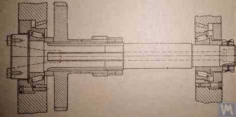
ਚਿੱਤਰ 3.18. ਦੋ-ਬੇਅਰਿੰਗ ਮਿਲਿੰਗ ਮਸ਼ੀਨ ਸਪਿੰਡਲ ਦਾ ਸਕੈਚ
ਚਿੱਤਰ 3.19 ਬੈਲੇਂਸਿੰਗ ਮਸ਼ੀਨ ਦੀ ਲੀਡਿੰਗ ਸਪਿੰਡਲ ਅਸੈਂਬਲੀ ਦੇ ਡਿਜ਼ਾਈਨ ਵੇਰੀਐਂਟਾਂ ਵਿੱਚੋਂ ਇੱਕ ਦਿਖਾਉਂਦਾ ਹੈ, ਜੋ ਦੋ ਰੇਡੀਏਲ-ਥਰਸਟ ਬੇਅਰਿੰਗਾਂ 'ਤੇ ਘੁੰਮਦਾ ਹੈ, ਜਿਨ੍ਹਾਂ ਵਿੱਚੋਂ ਹਰੇਕ ਦੀ ਆਪਣੀ ਸੁਤੰਤਰ ਹਾਊਸਿੰਗ 1 ਅਤੇ 2 ਹੈ। ਸਪਿੰਡਲ ਸ਼ਾਫਟ 3 'ਤੇ ਇੱਕ ਫਲੈਂਜ 4, ਜੋ ਕਾਰਡਨ ਸ਼ਾਫਟ ਦੀ ਫਲੈਂਜ ਮਾਊਂਟਿੰਗ ਲਈ ਹੈ, ਅਤੇ ਇੱਕ ਪੁਲੀ 5, ਜੋ V-ਬੈਲਟ ਡਰਾਈਵ ਦੀ ਵਰਤੋਂ ਕਰਕੇ ਇਲੈਕਟ੍ਰਿਕ ਮੋਟਰ ਤੋਂ ਸਪਿੰਡਲ ਤੱਕ ਰੋਟੇਸ਼ਨ ਟ੍ਰਾਂਸਮਿਟ ਕਰਨ ਲਈ ਵਰਤੀ ਜਾਂਦੀ ਹੈ, ਲਗਾਏ ਗਏ ਹਨ।
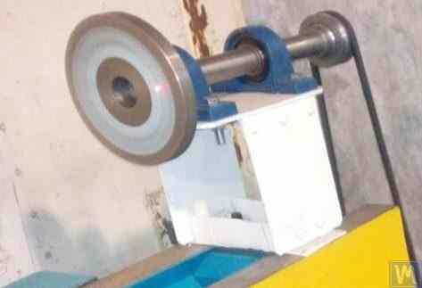
ਚਿੱਤਰ 3.19. ਦੋ ਸੁਤੰਤਰ ਬੇਅਰਿੰਗ ਸਪੋਰਟਾਂ 'ਤੇ ਸਪਿੰਡਲ ਡਿਜ਼ਾਈਨ ਦੀ ਉਦਾਹਰਨ
ਚਿੱਤਰ 3.20 ਅਤੇ 3.21 ਲੀਡਿੰਗ ਸਪਿੰਡਲ ਅਸੈਂਬਲੀਆਂ ਦੇ ਦੋ ਨੇੜਿਓਂ ਸੰਬੰਧਿਤ ਡਿਜ਼ਾਈਨ ਦਿਖਾਉਂਦਾ ਹੈ। ਦੋਹਾਂ ਮਾਮਲਿਆਂ ਵਿੱਚ, ਸਪਿੰਡਲ ਬੇਅਰਿੰਗਾਂ ਇੱਕ ਸਾਂਝੀ ਹਾਊਸਿੰਗ 1 ਵਿੱਚ ਲਗਾਈਆਂ ਜਾਂਦੀਆਂ ਹਨ, ਜਿਸ ਵਿੱਚ ਸਪਿੰਡਲ ਸ਼ਾਫਟ ਲਗਾਉਣ ਲਈ ਲੋੜੀਂਦਾ ਇੱਕ ਥਰੂ ਐਕਸੀਅਲ ਹੋਲ ਹੁੰਦਾ ਹੈ। ਇਸ ਹੋਲ ਦੇ ਪ੍ਰਵੇਸ਼ ਅਤੇ ਨਿਕਾਸ 'ਤੇ, ਹਾਊਸਿੰਗ ਵਿੱਚ ਖਾਸ ਬੋਰ (ਚਿੱਤਰਾਂ ਵਿੱਚ ਨਹੀਂ ਦਿਖਾਏ ਗਏ) ਹੁੰਦੇ ਹਨ, ਜੋ ਰੇਡੀਏਲ ਥਰਸਟ ਬੇਅਰਿੰਗਾਂ (ਰੋਲਰ ਜਾਂ ਬਾਲ) ਅਤੇ ਖਾਸ ਫਲੈਂਜ ਕਵਰਾਂ 5, ਜੋ ਬੇਅਰਿੰਗਾਂ ਦੀਆਂ ਬਾਹਰੀ ਰਿੰਗਾਂ ਨੂੰ ਸੁਰੱਖਿਅਤ ਕਰਨ ਲਈ ਵਰਤੇ ਜਾਂਦੇ ਹਨ, ਨੂੰ ਸਮਾਉਣ ਲਈ ਡਿਜ਼ਾਈਨ ਕੀਤੇ ਗਏ ਹਨ।
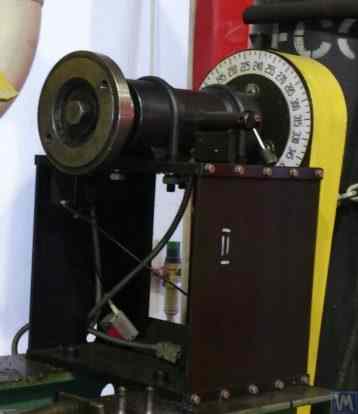
ਚਿੱਤਰ 3.20. ਸਾਂਝੀ ਹਾਊਸਿੰਗ ਵਿੱਚ ਲਗਾਏ ਗਏ ਦੋ ਬੇਅਰਿੰਗ ਸਪੋਰਟਾਂ 'ਤੇ ਲੀਡਿੰਗ ਸਪਿੰਡਲ ਡਿਜ਼ਾਈਨ ਦੀ ਉਦਾਹਰਨ 1
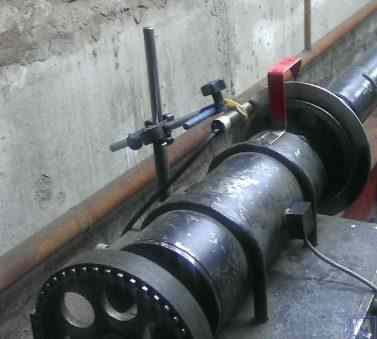
ਚਿੱਤਰ 3.21. ਸਾਂਝੀ ਹਾਊਸਿੰਗ ਵਿੱਚ ਲਗਾਏ ਗਏ ਦੋ ਬੇਅਰਿੰਗ ਸਪੋਰਟਾਂ 'ਤੇ ਲੀਡਿੰਗ ਸਪਿੰਡਲ ਡਿਜ਼ਾਈਨ ਦੀ ਉਦਾਹਰਨ 2
ਪਿਛਲੇ ਵੇਰੀਐਂਟ (ਦੇਖੋ ਚਿੱਤਰ 3.19) ਵਾਂਗ, ਸਪਿੰਡਲ ਸ਼ਾਫਟ 'ਤੇ ਇੱਕ ਫੇਸਪਲੇਟ 2 ਲਗਾਈ ਗਈ ਹੈ, ਜੋ ਡਰਾਈਵ ਸ਼ਾਫਟ ਦੀ ਫਲੈਂਜ ਮਾਊਂਟਿੰਗ ਲਈ ਹੈ, ਅਤੇ ਇੱਕ ਪੁਲੀ 3, ਜੋ ਬੈਲਟ ਡਰਾਈਵ ਰਾਹੀਂ ਇਲੈਕਟ੍ਰਿਕ ਮੋਟਰ ਤੋਂ ਸਪਿੰਡਲ ਤੱਕ ਰੋਟੇਸ਼ਨ ਟ੍ਰਾਂਸਮਿਟ ਕਰਨ ਲਈ ਵਰਤੀ ਜਾਂਦੀ ਹੈ। ਸਪਿੰਡਲ ਸ਼ਾਫਟ 'ਤੇ ਇੱਕ ਲਿੰਬ 4 ਵੀ ਫਿਕਸ ਕੀਤਾ ਗਿਆ ਹੈ, ਜੋ ਸਪਿੰਡਲ ਦੀ ਐਂਗੁਲਰ ਸਥਿਤੀ ਨਿਰਧਾਰਤ ਕਰਨ ਲਈ ਵਰਤਿਆ ਜਾਂਦਾ ਹੈ, ਜੋ ਬੈਲੇਂਸਿੰਗ ਦੌਰਾਨ ਰੋਟਰ 'ਤੇ ਟੈਸਟ ਅਤੇ ਕਰੈਕਸ਼ਨ ਵੇਟ ਲਗਾਉਣ ਵੇਲੇ ਵਰਤਿਆ ਜਾਂਦਾ ਹੈ।
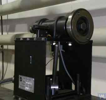
ਚਿੱਤਰ 3.22. ਇੱਕ ਡਰਿਵਨ (ਪਿਛਲੀ) ਸਪਿੰਡਲ ਦੇ ਡਿਜ਼ਾਈਨ ਦੀ ਉਦਾਹਰਨ
ਚਿੱਤਰ 3.22 ਮਸ਼ੀਨ ਦੀ ਡਰਿਵਨ (ਪਿਛਲੀ) ਸਪਿੰਡਲ ਅਸੈਂਬਲੀ ਦਾ ਇੱਕ ਡਿਜ਼ਾਈਨ ਵੇਰੀਐਂਟ ਦਿਖਾਉਂਦਾ ਹੈ, ਜੋ ਲੀਡਿੰਗ ਸਪਿੰਡਲ ਤੋਂ ਸਿਰਫ਼ ਡਰਾਈਵ ਪੁਲੀ ਅਤੇ ਲਿੰਬ ਦੀ ਗ਼ੈਰ-ਮੌਜੂਦਗੀ ਕਾਰਨ ਵੱਖਰਾ ਹੈ, ਕਿਉਂਕਿ ਉਨ੍ਹਾਂ ਦੀ ਲੋੜ ਨਹੀਂ ਹੈ।
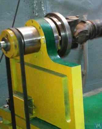
ਚਿੱਤਰ 3.23। ਇੱਕ ਚਲਾਏ ਜਾਂਦੇ (ਪਿਛਲੇ) ਸਪਿੰਡਲ ਦੇ ਡਿਜ਼ਾਈਨ ਐਗਜ਼ੀਕਿਊਸ਼ਨ ਦੀ ਉਦਾਹਰਣ
ਜਿਵੇਂ ਕਿ ਦੇਖਿਆ ਗਿਆ ਚਿੱਤਰ 3.20 – 3.22, ਉੱਪਰ ਦੱਸੀਆਂ ਸਪਿੰਡਲ ਅਸੈਂਬਲੀਆਂ ਨੂੰ ਖਾਸ ਕਲੈਂਪਾਂ (ਸਟ੍ਰੈਪਾਂ) 6 ਦੀ ਵਰਤੋਂ ਕਰਕੇ ਬੈਲੇਂਸਿੰਗ ਮਸ਼ੀਨਾਂ ਦੇ ਸੌਫਟ ਬੇਅਰਿੰਗ ਸਪੋਰਟਾਂ ਨਾਲ ਜੋੜਿਆ ਜਾਂਦਾ ਹੈ। ਲੋੜ ਪੈਣ 'ਤੇ ਹੋਰ ਲਗਾਵ ਤਰੀਕੇ ਵੀ ਵਰਤੇ ਜਾ ਸਕਦੇ ਹਨ, ਜੋ ਸਪੋਰਟ 'ਤੇ ਸਪਿੰਡਲ ਅਸੈਂਬਲੀ ਦੀ ਸਹੀ ਕਠੋਰਤਾ ਅਤੇ ਸਥਿਤੀ ਦੀ ਸ਼ੁੱਧਤਾ ਯਕੀਨੀ ਬਣਾਉਂਦੇ ਹਨ।
ਚਿੱਤਰ 3.23 ਉਸ ਸਪਿੰਡਲ ਵਰਗੀ ਫਲੈਂਜ ਮਾਊਂਟਿੰਗ ਦਾ ਇੱਕ ਡਿਜ਼ਾਈਨ ਦਰਸਾਉਂਦਾ ਹੈ, ਜਿਸ ਨੂੰ ਬੈਲੇਂਸਿੰਗ ਮਸ਼ੀਨ ਦੇ ਹਾਰਡ ਬੇਅਰਿੰਗ ਸਪੋਰਟ 'ਤੇ ਇਸ ਦੀ ਇੰਸਟਾਲੇਸ਼ਨ ਲਈ ਵਰਤਿਆ ਜਾ ਸਕਦਾ ਹੈ।
3.2.1.3.4. ਸਪਿੰਡਲ ਦੀ ਕਠੋਰਤਾ ਅਤੇ ਰੇਡੀਅਲ ਰਨਆਊਟ ਦੀ ਗਣਨਾ
ਸਪਿੰਡਲ ਦੀ ਕਠੋਰਤਾ ਅਤੇ ਸੰਭਾਵਿਤ ਰੇਡੀਅਲ ਰਨਆਊਟ ਨਿਰਧਾਰਤ ਕਰਨ ਲਈ, ਫਾਰਮੂਲਾ 3.4 ਵਰਤਿਆ ਜਾ ਸਕਦਾ ਹੈ (ਚਿੱਤਰ 3.24 ਵਿੱਚ ਗਣਨਾ ਸਕੀਮ ਦੇਖੋ):
ਜਿੱਥੇ:
- Y - ਸਪਿੰਡਲ ਕੰਸੋਲ ਦੇ ਸਿਰੇ 'ਤੇ ਸਪਿੰਡਲ ਦੀ ਇਲਾਸਟਿਕ ਵਿਸਥਾਪਨ, cm;
- P - ਸਪਿੰਡਲ ਕੰਸੋਲ 'ਤੇ ਲੱਗਣ ਵਾਲਾ ਗਣਨਾ ਕੀਤਾ ਲੋਡ, kg;
- A - ਸਪਿੰਡਲ ਦਾ ਪਿਛਲਾ ਬੇਅਰਿੰਗ ਸਪੋਰਟ;
- B - ਸਪਿੰਡਲ ਦਾ ਅਗਲਾ ਬੇਅਰਿੰਗ ਸਪੋਰਟ;
- g - ਸਪਿੰਡਲ ਕੰਸੋਲ ਦੀ ਲੰਬਾਈ, cm;
- c - ਸਪਿੰਡਲ ਦੇ ਸਪੋਰਟ A ਅਤੇ B ਵਿਚਕਾਰ ਦੂਰੀ, cm;
- J1 - ਸਪੋਰਟਾਂ ਵਿਚਕਾਰ ਸਪਿੰਡਲ ਸੈਕਸ਼ਨ ਦਾ ਔਸਤ ਜੜਤਾ ਪਲ, cm⁴;
- J2 - ਸਪਿੰਡਲ ਕੰਸੋਲ ਸੈਕਸ਼ਨ ਦਾ ਔਸਤ ਜੜਤਾ ਪਲ, cm⁴;
- jB ਅਤੇ jA - ਸਪਿੰਡਲ ਦੇ ਅਗਲੇ ਅਤੇ ਪਿਛਲੇ ਸਪੋਰਟਾਂ ਲਈ ਕ੍ਰਮਵਾਰ ਬੇਅਰਿੰਗਾਂ ਦੀ ਕਠੋਰਤਾ, kg/cm।
ਫਾਰਮੂਲਾ 3.4 ਨੂੰ ਬਦਲ ਕੇ, ਸਪਿੰਡਲ ਅਸੈਂਬਲੀ ਕਠੋਰਤਾ ਦਾ ਲੋੜੀਂਦਾ ਗਣਨਾ ਕੀਤਾ ਮੁੱਲ jшп ਨਿਰਧਾਰਤ ਕੀਤਾ ਜਾ ਸਕਦਾ ਹੈ:
ਮੱਧਮ ਆਕਾਰ ਦੀਆਂ ਬੈਲੇਂਸਿੰਗ ਮਸ਼ੀਨਾਂ ਲਈ ਕੰਮ [1] ਦੀਆਂ ਸਿਫ਼ਾਰਸ਼ਾਂ ਨੂੰ ਧਿਆਨ ਵਿੱਚ ਰੱਖਦੇ ਹੋਏ, ਇਹ ਮੁੱਲ 50 kg/µm ਤੋਂ ਘੱਟ ਨਹੀਂ ਹੋਣਾ ਚਾਹੀਦਾ।
ਰੇਡੀਅਲ ਰਨਆਊਟ ਦੀ ਗਣਨਾ ਲਈ, ਫਾਰਮੂਲਾ 3.5 ਵਰਤਿਆ ਜਾਂਦਾ ਹੈ:
ਜਿੱਥੇ:
- ∆ ਸਪਿੰਡਲ ਕਨਸੋਲ ਸਿਰੇ 'ਤੇ ਰੇਡੀਏਲ ਰਨਆਊਟ ਹੈ, µm;
- ∆B ਫਰੰਟ ਸਪਿੰਡਲ ਬੇਅਰਿੰਗ ਦਾ ਰੇਡੀਏਲ ਰਨਆਊਟ ਹੈ, µm;
- ∆A ਰੀਅਰ ਸਪਿੰਡਲ ਬੇਅਰਿੰਗ ਦਾ ਰੇਡੀਏਲ ਰਨਆਊਟ ਹੈ, µm;
- g ਸਪਿੰਡਲ ਕਨਸੋਲ ਦੀ ਲੰਬਾਈ ਹੈ, cm;
- c ਸਪਿੰਡਲ ਦੇ ਸਪੋਰਟ A ਅਤੇ B ਵਿਚਕਾਰ ਦੂਰੀ ਹੈ, cm।
3.2.1.3.5. ਸਪਿੰਡਲ ਬੈਲੇਂਸ ਲੋੜਾਂ ਨੂੰ ਯਕੀਨੀ ਬਣਾਉਣਾ
ਬੈਲੰਸਿੰਗ ਮਸ਼ੀਨਾਂ ਦੀਆਂ ਸਪਿੰਡਲ ਅਸੈਂਬਲੀਆਂ ਚੰਗੀ ਤਰ੍ਹਾਂ ਬੈਲੰਸ ਹੋਣੀਆਂ ਚਾਹੀਦੀਆਂ ਹਨ, ਕਿਉਂਕਿ ਕੋਈ ਵੀ ਅਸਲ ਅਸੰਤੁਲਨ ਬੈਲੰਸ ਕੀਤੇ ਜਾ ਰਹੇ ਰੋਟਰ ਵਿੱਚ ਵਾਧੂ ਗਲਤੀ ਵਜੋਂ ਟ੍ਰਾਂਸਫਰ ਹੋ ਜਾਵੇਗਾ। ਸਪਿੰਡਲ ਦੇ ਬਾਕੀ ਬਚੇ ਅਸੰਤੁਲਨ ਲਈ ਤਕਨੀਕੀ ਸਹਿਣਸ਼ੀਲਤਾ ਨਿਰਧਾਰਤ ਕਰਦੇ ਸਮੇਂ, ਆਮ ਤੌਰ 'ਤੇ ਇਹ ਸਲਾਹ ਦਿੱਤੀ ਜਾਂਦੀ ਹੈ ਕਿ ਇਸਦੀ ਬੈਲੰਸਿੰਗ ਦੀ ਸ਼ੁੱਧਤਾ ਸ਼੍ਰੇਣੀ, ਮਸ਼ੀਨ 'ਤੇ ਬੈਲੰਸ ਕੀਤੇ ਜਾ ਰਹੇ ਉਤਪਾਦ ਨਾਲੋਂ ਘੱਟੋ-ਘੱਟ 1-2 ਸ਼੍ਰੇਣੀਆਂ ਵੱਧ ਹੋਣੀ ਚਾਹੀਦੀ ਹੈ।
ਉੱਪਰ ਦੱਸੀਆਂ ਸਪਿੰਡਲਾਂ ਦੀਆਂ ਡਿਜ਼ਾਈਨ ਵਿਸ਼ੇਸ਼ਤਾਵਾਂ ਨੂੰ ਧਿਆਨ ਵਿੱਚ ਰੱਖਦੇ ਹੋਏ, ਉਨ੍ਹਾਂ ਦੀ ਬੈਲੇਂਸਿੰਗ ਦੋ ਪਲੇਨਾਂ ਵਿੱਚ ਕੀਤੀ ਜਾਣੀ ਚਾਹੀਦੀ ਹੈ।
3.2.1.3.6. ਸਪਿੰਡਲ ਬੇਅਰਿੰਗਾਂ ਲਈ ਬੇਅਰਿੰਗ ਲੋਡ ਸਮਰੱਥਾ ਅਤੇ ਟਿਕਾਊਪਣ ਦੀਆਂ ਲੋੜਾਂ ਯਕੀਨੀ ਬਣਾਉਣਾ
ਸਪਿੰਡਲ ਡਿਜ਼ਾਈਨ ਕਰਦੇ ਸਮੇਂ ਅਤੇ ਬੇਅਰਿੰਗ ਆਕਾਰ ਚੁਣਦੇ ਸਮੇਂ, ਬੇਅਰਿੰਗਾਂ ਦੀ ਟਿਕਾਊਤਾ ਅਤੇ ਲੋਡ ਸਮਰੱਥਾ ਦਾ ਪਹਿਲਾਂ ਤੋਂ ਮੁਲਾਂਕਣ ਕਰਨ ਦੀ ਸਲਾਹ ਦਿੱਤੀ ਜਾਂਦੀ ਹੈ। ਇਹਨਾਂ ਗਣਨਾਵਾਂ ਨੂੰ ਕਰਨ ਦੀ ਵਿਧੀ ISO 281 "Rolling Bearings - Dynamic Load Ratings and Rating Life" [3] ਵਿੱਚ ਵਿਸਥਾਰ ਨਾਲ ਦਿੱਤੀ ਜਾ ਸਕਦੀ ਹੈ, ਅਤੇ ਨਾਲ ਹੀ ਕਈ (ਡਿਜੀਟਲ ਸਮੇਤ) ਰੋਲਿੰਗ ਬੇਅਰਿੰਗ ਹੈਂਡਬੁੱਕਾਂ ਵਿੱਚ ਵੀ।
3.2.1.3.7. ਸਪਿੰਡਲ ਬੇਅਰਿੰਗਾਂ ਦੇ ਸਵੀਕਾਰਯੋਗ ਗਰਮ ਹੋਣ ਲਈ ਲੋੜਾਂ ਯਕੀਨੀ ਬਣਾਉਣਾ
ਕੰਮ [1] ਦੀਆਂ ਸਿਫ਼ਾਰਸ਼ਾਂ ਅਨੁਸਾਰ, ਸਪਿੰਡਲ ਬੇਅਰਿੰਗਾਂ ਦੀਆਂ ਬਾਹਰੀ ਰਿੰਗਾਂ ਦਾ ਵੱਧ ਤੋਂ ਵੱਧ ਸਵੀਕਾਰਯੋਗ ਗਰਮ ਹੋਣਾ 70°C ਤੋਂ ਵੱਧ ਨਹੀਂ ਹੋਣਾ ਚਾਹੀਦਾ। ਹਾਲਾਂਕਿ, ਉੱਚ-ਗੁਣਵੱਤਾ ਵਾਲੀ ਬੈਲੇਂਸਿੰਗ ਯਕੀਨੀ ਬਣਾਉਣ ਲਈ, ਬਾਹਰੀ ਰਿੰਗਾਂ ਦਾ ਸਿਫ਼ਾਰਸ਼ ਕੀਤਾ ਗਰਮ ਹੋਣਾ 40 – 45°C ਤੋਂ ਵੱਧ ਨਹੀਂ ਹੋਣਾ ਚਾਹੀਦਾ।
3.2.1.3.8. ਸਪਿੰਡਲ ਲਈ ਬੈਲਟ ਡਰਾਈਵ ਦੀ ਕਿਸਮ ਅਤੇ ਡਰਾਈਵ ਪੁਲੀ ਦੇ ਡਿਜ਼ਾਈਨ ਦੀ ਚੋਣ ਕਰਨਾ
ਬੈਲੈਂਸਿੰਗ ਮਸ਼ੀਨ ਦੇ ਡਰਾਈਵਿੰਗ ਸਪਿੰਡਲ ਨੂੰ ਡਿਜ਼ਾਈਨ ਕਰਦੇ ਸਮੇਂ, ਇਸ ਦੀ ਘੁੰਮਣ ਗਤੀ ਨੂੰ ਫਲੈਟ ਬੈਲਟ ਡਰਾਈਵ ਦੀ ਵਰਤੋਂ ਨਾਲ ਯਕੀਨੀ ਬਣਾਉਣ ਦੀ ਸਿਫ਼ਾਰਸ਼ ਕੀਤੀ ਜਾਂਦੀ ਹੈ। ਸਪਿੰਡਲ ਦੇ ਸੰਚਾਲਨ ਲਈ ਅਜਿਹੀ ਡਰਾਈਵ ਦੀ ਸਹੀ ਵਰਤੋਂ ਦੀ ਇੱਕ ਉਦਾਹਰਨ ਇੱਥੇ ਦਿਖਾਈ ਗਈ ਹੈ ਚਿੱਤਰ 3.20 ਅਤੇ 3.23। V-ਬੈਲਟ ਜਾਂ ਦੰਦੇਦਾਰ ਬੈਲਟ ਡਰਾਈਵਾਂ ਦੀ ਵਰਤੋਂ ਕਰਨਾ ਅਣਚਾਹਿਆ ਹੈ, ਕਿਉਂਕਿ ਇਹ ਬੈਲਟਾਂ ਅਤੇ ਪੁਲੀਆਂ ਵਿੱਚ ਜਿਓਮੈਟ੍ਰਿਕ ਅਸ਼ੁੱਧੀਆਂ ਕਾਰਨ ਸਪਿੰਡਲ 'ਤੇ ਵਾਧੂ ਡਾਇਨਾਮਿਕ ਲੋਡ ਲਗਾ ਸਕਦੀਆਂ ਹਨ, ਜੋ ਬਦਲੇ ਵਿੱਚ ਬੈਲੇਂਸਿੰਗ ਦੌਰਾਨ ਵਾਧੂ ਮਾਪ ਗਲਤੀਆਂ ਦਾ ਕਾਰਨ ਬਣ ਸਕਦੀਆਂ ਹਨ। ਫਲੈਟ ਡਰਾਈਵ ਬੈਲਟਾਂ ਲਈ ਪੁਲੀਆਂ ਵਾਸਤੇ ਸਿਫ਼ਾਰਸ਼ੀ ਲੋੜਾਂ ਰਾਸ਼ਟਰੀ ਮਿਆਰ GOST 17383-73 "Pulleys for flat drive belts" [4] ਵਿੱਚ ਦੱਸੀਆਂ ਗਈਆਂ ਹਨ।
ਡਰਾਈਵ ਪੁਲੀ ਨੂੰ ਸਪਿੰਡਲ ਦੇ ਪਿਛਲੇ ਸਿਰੇ 'ਤੇ, ਬੇਅਰਿੰਗ ਅਸੈਂਬਲੀ ਦੇ ਜਿੰਨਾ ਸੰਭਵ ਹੋ ਸਕੇ ਨੇੜੇ (ਘੱਟੋ-ਘੱਟ ਸੰਭਵ ਓਵਰਹੈਂਗ ਨਾਲ) ਸਥਿਤ ਹੋਣਾ ਚਾਹੀਦਾ ਹੈ। ਪੁਲੀ ਦੀ ਓਵਰਹੈਂਗਿੰਗ ਪਲੇਸਮੈਂਟ ਲਈ ਲਿਆ ਗਿਆ ਡਿਜ਼ਾਈਨ ਫੈਸਲਾ, ਜੋ ਇੱਥੇ ਦਿਖਾਏ ਗਏ ਸਪਿੰਡਲ ਦੇ ਨਿਰਮਾਣ ਵਿੱਚ ਕੀਤਾ ਗਿਆ ਚਿੱਤਰ 3.19, ਨੂੰ ਅਸਫਲ ਮੰਨਿਆ ਜਾ ਸਕਦਾ ਹੈ, ਕਿਉਂਕਿ ਇਹ ਸਪਿੰਡਲ ਸਪੋਰਟਾਂ 'ਤੇ ਕੰਮ ਕਰਨ ਵਾਲੇ ਗਤੀਸ਼ੀਲ ਡਰਾਈਵ ਲੋਡ ਦੇ ਪਲ ਨੂੰ ਕਾਫ਼ੀ ਵਧਾ ਦਿੰਦਾ ਹੈ।
ਇਸ ਡਿਜ਼ਾਈਨ ਦੀ ਇੱਕ ਹੋਰ ਮਹੱਤਵਪੂਰਨ ਖਾਮੀ ਵੀ-ਬੈਲਟ ਡਰਾਈਵ ਦੀ ਵਰਤੋਂ ਹੈ, ਜਿਸ ਦੀਆਂ ਨਿਰਮਾਣ ਅਤੇ ਅਸੈਂਬਲੀ ਸੰਬੰਧੀ ਗਲਤੀਆਂ ਵੀ ਸਪਿੰਡਲ 'ਤੇ ਅਣਚਾਹੇ ਵਾਧੂ ਲੋਡ ਦਾ ਸਰੋਤ ਬਣ ਸਕਦੀਆਂ ਹਨ।
3.3. ਬੈੱਡ (ਫਰੇਮ)
ਬੈੱਡ ਬੈਲੈਂਸਿੰਗ ਮਸ਼ੀਨ ਦਾ ਮੁੱਖ ਸਹਾਇਕ ਢਾਂਚਾ ਹੈ, ਜਿਸ 'ਤੇ ਇਸ ਦੇ ਮੁੱਖ ਤੱਤ ਆਧਾਰਿਤ ਹੁੰਦੇ ਹਨ, ਜਿਸ ਵਿੱਚ ਸਪੋਰਟ ਪੋਸਟਾਂ ਅਤੇ ਡਰਾਈਵ ਮੋਟਰ ਸ਼ਾਮਲ ਹਨ। ਬੈਲੈਂਸਿੰਗ ਮਸ਼ੀਨ ਦਾ ਬੈੱਡ ਚੁਣਦੇ ਜਾਂ ਬਣਾਉਂਦੇ ਸਮੇਂ, ਇਹ ਯਕੀਨੀ ਬਣਾਉਣਾ ਜ਼ਰੂਰੀ ਹੈ ਕਿ ਇਹ ਕਈ ਲੋੜਾਂ ਪੂਰੀਆਂ ਕਰੇ, ਜਿਸ ਵਿੱਚ ਲੋੜੀਂਦੀ ਕਠੋਰਤਾ, ਜਿਓਮੈਟ੍ਰਿਕ ਸ਼ੁੱਧਤਾ, ਵਾਈਬ੍ਰੇਸ਼ਨ ਪ੍ਰਤੀਰੋਧ ਅਤੇ ਇਸ ਦੀਆਂ ਗਾਈਡਾਂ ਦਾ ਘਿਸਾਵ ਪ੍ਰਤੀਰੋਧ ਸ਼ਾਮਲ ਹੈ।
ਅਭਿਆਸ ਦਰਸਾਉਂਦਾ ਹੈ ਕਿ ਆਪਣੀਆਂ ਲੋੜਾਂ ਲਈ ਮਸ਼ੀਨਾਂ ਬਣਾਉਂਦੇ ਸਮੇਂ, ਹੇਠ ਲਿਖੇ ਬੈੱਡ ਵਿਕਲਪ ਸਭ ਤੋਂ ਵੱਧ ਵਰਤੇ ਜਾਂਦੇ ਹਨ:
- ਪੁਰਾਣੀਆਂ ਧਾਤ-ਕੱਟਣ ਵਾਲੀਆਂ ਮਸ਼ੀਨਾਂ (ਲੇਥ, ਲੱਕੜ ਦਾ ਕੰਮ ਕਰਨ ਵਾਲੀਆਂ ਮਸ਼ੀਨਾਂ, ਆਦਿ) ਤੋਂ ਕਾਸਟ ਆਇਰਨ ਬੈੱਡ;
- ਚੈਨਲਾਂ 'ਤੇ ਆਧਾਰਿਤ, ਬੋਲਟ ਕਨੈਕਸ਼ਨਾਂ ਦੀ ਵਰਤੋਂ ਕਰਕੇ ਜੋੜੇ ਗਏ ਅਸੈਂਬਲਡ ਬੈੱਡ;
- ਚੈਨਲਾਂ 'ਤੇ ਆਧਾਰਿਤ ਵੈਲਡਡ ਬੈੱਡ;
- ਵਾਈਬ੍ਰੇਸ਼ਨ-ਸੋਖਣ ਵਾਲੀਆਂ ਕੋਟਿੰਗਾਂ ਵਾਲੇ ਪੌਲੀਮਰ ਕੰਕਰੀਟ ਬੈੱਡ।
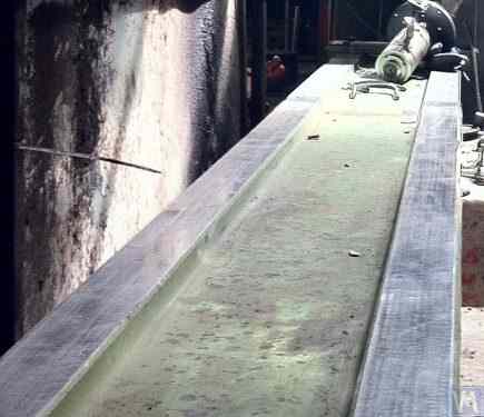
ਚਿੱਤਰ 3.25। ਕਾਰਡਨ ਸ਼ਾਫਟਾਂ ਦੀ ਬੈਲੈਂਸਿੰਗ ਲਈ ਮਸ਼ੀਨ ਬਣਾਉਣ ਵਾਸਤੇ ਵਰਤੀ ਗਈ ਪੁਰਾਣੀ ਲੱਕੜ ਦਾ ਕੰਮ ਕਰਨ ਵਾਲੀ ਮਸ਼ੀਨ ਦੇ ਬੈੱਡ ਦੀ ਵਰਤੋਂ ਦੀ ਉਦਾਹਰਨ।
3.4. ਬੈਲੇਂਸਿੰਗ ਮਸ਼ੀਨਾਂ ਲਈ ਡਰਾਈਵ
ਜਿਵੇਂ ਕਿ ਸਾਡੇ ਗਾਹਕਾਂ ਦੁਆਰਾ ਬੈਲੈਂਸਿੰਗ ਮਸ਼ੀਨਾਂ ਦੇ ਨਿਰਮਾਣ ਵਿੱਚ ਵਰਤੇ ਗਏ ਡਿਜ਼ਾਈਨ ਹੱਲਾਂ ਦਾ ਵਿਸ਼ਲੇਸ਼ਣ ਦਰਸਾਉਂਦਾ ਹੈ, ਉਹ ਮੁੱਖ ਤੌਰ 'ਤੇ ਡਰਾਈਵਾਂ ਦੇ ਡਿਜ਼ਾਈਨ ਦੌਰਾਨ ਵੇਰੀਏਬਲ ਫ੍ਰੀਕੁਐਂਸੀ ਡਰਾਈਵਾਂ ਨਾਲ ਲੈਸ AC ਮੋਟਰਾਂ ਦੀ ਵਰਤੋਂ 'ਤੇ ਧਿਆਨ ਕੇਂਦਰਿਤ ਕਰਦੇ ਹਨ। ਇਹ ਪਹੁੰਚ ਘੱਟੋ-ਘੱਟ ਲਾਗਤ ਨਾਲ ਬੈਲੈਂਸ ਕੀਤੇ ਗਏ ਰੋਟਰਾਂ ਲਈ ਵਿਵਸਥਿਤ ਘੁੰਮਣ ਗਤੀ ਦੀ ਵਿਸ਼ਾਲ ਰੇਂਜ ਦੀ ਆਗਿਆ ਦਿੰਦੀ ਹੈ। ਬੈਲੈਂਸ ਕੀਤੇ ਗਏ ਰੋਟਰਾਂ ਨੂੰ ਘੁੰਮਾਉਣ ਲਈ ਵਰਤੀਆਂ ਜਾਂਦੀਆਂ ਮੁੱਖ ਡਰਾਈਵ ਮੋਟਰਾਂ ਦੀ ਸ਼ਕਤੀ ਆਮ ਤੌਰ 'ਤੇ ਇਹਨਾਂ ਰੋਟਰਾਂ ਦੇ ਪੁੰਜ ਦੇ ਆਧਾਰ 'ਤੇ ਚੁਣੀ ਜਾਂਦੀ ਹੈ ਅਤੇ ਲਗਭਗ ਹੋ ਸਕਦੀ ਹੈ:
- ≤ 5 kg ਭਾਰ ਵਾਲੇ ਰੋਟਰਾਂ ਦੀ ਬੈਲੰਸਿੰਗ ਲਈ ਡਿਜ਼ਾਈਨ ਕੀਤੀਆਂ ਮਸ਼ੀਨਾਂ ਲਈ 0.25 - 0.72 kW;
- 5 ਤੋਂ ≤ 50 kg ਭਾਰ ਵਾਲੇ ਰੋਟਰਾਂ ਦੀ ਬੈਲੰਸਿੰਗ ਲਈ ਡਿਜ਼ਾਈਨ ਕੀਤੀਆਂ ਮਸ਼ੀਨਾਂ ਲਈ 0.72 - 1.2 kW;
- 1.2 - 1.5 kW ਉਹਨਾਂ ਮਸ਼ੀਨਾਂ ਲਈ ਜੋ > 50 ≤ 100 kg ਪੁੰਜ ਵਾਲੇ ਰੋਟਰਾਂ ਨੂੰ ਬੈਲੈਂਸ ਕਰਨ ਲਈ ਤਿਆਰ ਕੀਤੀਆਂ ਗਈਆਂ ਹਨ;
- 1.5 - 2.2 kW ਉਹਨਾਂ ਮਸ਼ੀਨਾਂ ਲਈ ਜੋ > 100 ≤ 500 kg ਪੁੰਜ ਵਾਲੇ ਰੋਟਰਾਂ ਨੂੰ ਬੈਲੈਂਸ ਕਰਨ ਲਈ ਤਿਆਰ ਕੀਤੀਆਂ ਗਈਆਂ ਹਨ;
- 2.2 - 5 kW ਉਹਨਾਂ ਮਸ਼ੀਨਾਂ ਲਈ ਜੋ > 500 ≤ 1000 kg ਪੁੰਜ ਵਾਲੇ ਰੋਟਰਾਂ ਨੂੰ ਬੈਲੈਂਸ ਕਰਨ ਲਈ ਤਿਆਰ ਕੀਤੀਆਂ ਗਈਆਂ ਹਨ;
- 5 - 7.5 kW ਉਹਨਾਂ ਮਸ਼ੀਨਾਂ ਲਈ ਜੋ > 1000 ≤ 3000 kg ਪੁੰਜ ਵਾਲੇ ਰੋਟਰਾਂ ਨੂੰ ਬੈਲੈਂਸ ਕਰਨ ਲਈ ਤਿਆਰ ਕੀਤੀਆਂ ਗਈਆਂ ਹਨ।
ਇਹਨਾਂ ਮੋਟਰਾਂ ਨੂੰ ਮਸ਼ੀਨ ਬੈੱਡ ਜਾਂ ਇਸ ਦੀ ਬੁਨਿਆਦ 'ਤੇ ਸਖ਼ਤੀ ਨਾਲ ਮਾਊਂਟ ਕੀਤਾ ਜਾਣਾ ਚਾਹੀਦਾ ਹੈ। ਮਸ਼ੀਨ 'ਤੇ ਲਗਾਉਣ ਤੋਂ ਪਹਿਲਾਂ (ਜਾਂ ਇੰਸਟਾਲੇਸ਼ਨ ਸਾਈਟ 'ਤੇ), ਮੁੱਖ ਡਰਾਈਵ ਮੋਟਰ ਨੂੰ, ਇਸ ਦੇ ਆਊਟਪੁੱਟ ਸ਼ਾਫਟ 'ਤੇ ਮਾਊਂਟ ਕੀਤੀ ਪੁਲੀ ਸਮੇਤ, ਧਿਆਨ ਨਾਲ ਬੈਲੈਂਸ ਕੀਤਾ ਜਾਣਾ ਚਾਹੀਦਾ ਹੈ। ਵੇਰੀਏਬਲ ਫ੍ਰੀਕੁਐਂਸੀ ਡਰਾਈਵ ਕਾਰਨ ਹੋਣ ਵਾਲੀ ਇਲੈਕਟ੍ਰੋਮੈਗਨੈਟਿਕ ਦਖ਼ਲਅੰਦਾਜ਼ੀ ਨੂੰ ਘਟਾਉਣ ਲਈ, ਇਸ ਦੇ ਇਨਪੁੱਟ ਅਤੇ ਆਊਟਪੁੱਟ 'ਤੇ ਨੈੱਟਵਰਕ ਫਿਲਟਰ ਲਗਾਉਣ ਦੀ ਸਿਫ਼ਾਰਸ਼ ਕੀਤੀ ਜਾਂਦੀ ਹੈ। ਇਹ ਡਰਾਈਵਾਂ ਦੇ ਨਿਰਮਾਤਾਵਾਂ ਦੁਆਰਾ ਸਪਲਾਈ ਕੀਤੇ ਗਏ ਸਟੈਂਡਰਡ ਤਿਆਰ ਉਤਪਾਦ ਜਾਂ ਫੈਰਾਈਟ ਰਿੰਗਾਂ ਦੀ ਵਰਤੋਂ ਕਰਕੇ ਬਣਾਏ ਗਏ ਘਰੇਲੂ ਫਿਲਟਰ ਹੋ ਸਕਦੇ ਹਨ।
4. ਬੈਲੇਂਸਿੰਗ ਮਸ਼ੀਨਾਂ ਦੇ ਮਾਪਣ ਸਿਸਟਮ
ਬੈਲੈਂਸਿੰਗ ਮਸ਼ੀਨਾਂ ਦੇ ਜ਼ਿਆਦਾਤਰ ਸ਼ੌਕੀਨ ਨਿਰਮਾਤਾ, ਜੋ LLC "Kinematics" (Vibromera) ਨਾਲ ਸੰਪਰਕ ਕਰਦੇ ਹਨ, ਆਪਣੇ ਡਿਜ਼ਾਈਨਾਂ ਵਿੱਚ ਸਾਡੀ ਕੰਪਨੀ ਦੁਆਰਾ ਬਣਾਏ "Balanset" ਲੜੀ ਦੀਆਂ ਮਾਪਣ ਪ੍ਰਣਾਲੀਆਂ ਦੀ ਵਰਤੋਂ ਕਰਨ ਦੀ ਯੋਜਨਾ ਬਣਾਉਂਦੇ ਹਨ। ਹਾਲਾਂਕਿ, ਕੁਝ ਗਾਹਕ ਅਜਿਹੇ ਮਾਪਣ ਪ੍ਰਣਾਲੀਆਂ ਨੂੰ ਸੁਤੰਤਰ ਤੌਰ 'ਤੇ ਬਣਾਉਣ ਦੀ ਵੀ ਯੋਜਨਾ ਬਣਾਉਂਦੇ ਹਨ। ਇਸ ਲਈ, ਬੈਲੈਂਸਿੰਗ ਮਸ਼ੀਨ ਲਈ ਮਾਪਣ ਪ੍ਰਣਾਲੀ ਦੇ ਨਿਰਮਾਣ ਬਾਰੇ ਵਧੇਰੇ ਵਿਸਥਾਰ ਵਿੱਚ ਚਰਚਾ ਕਰਨਾ ਸਮਝਦਾਰੀ ਭਰਿਆ ਹੈ। ਇਹਨਾਂ ਪ੍ਰਣਾਲੀਆਂ ਦੀ ਮੁੱਖ ਲੋੜ ਹੈ ਵਾਈਬ੍ਰੇਸ਼ਨ ਸਿਗਨਲ ਦੇ ਰੋਟੇਸ਼ਨਲ ਕੰਪੋਨੈਂਟ ਦੇ ਐਂਪਲੀਟਿਊਡ ਅਤੇ ਫੇਜ਼ ਦੀ ਉੱਚ-ਸ਼ੁੱਧਤਾ ਮਾਪ ਪ੍ਰਦਾਨ ਕਰਨ ਦੀ ਲੋੜ, ਜੋ ਬੈਲੈਂਸ ਕੀਤੇ ਜਾ ਰਹੇ ਰੋਟਰ ਦੀ ਰੋਟੇਸ਼ਨ ਫ੍ਰੀਕੁਐਂਸੀ 'ਤੇ ਦਿਖਾਈ ਦਿੰਦਾ ਹੈ। ਇਹ ਟੀਚਾ ਆਮ ਤੌਰ 'ਤੇ ਤਕਨੀਕੀ ਹੱਲਾਂ ਦੇ ਸੁਮੇਲ ਦੀ ਵਰਤੋਂ ਕਰਕੇ ਪ੍ਰਾਪਤ ਕੀਤਾ ਜਾਂਦਾ ਹੈ, ਜਿਸ ਵਿੱਚ ਸ਼ਾਮਲ ਹਨ:
- ਉੱਚ ਸਿਗਨਲ ਪਰਿਵਰਤਨ ਗੁਣਾਂਕ ਵਾਲੇ ਵਾਈਬ੍ਰੇਸ਼ਨ ਸੈਂਸਰਾਂ ਦੀ ਵਰਤੋਂ;
- ਆਧੁਨਿਕ ਲੇਜ਼ਰ ਫੇਜ਼ ਐਂਗਲ ਸੈਂਸਰਾਂ ਦੀ ਵਰਤੋਂ;
- ਸੈਂਸਰ ਸਿਗਨਲਾਂ (ਪ੍ਰਾਇਮਰੀ ਸਿਗਨਲ ਪ੍ਰੋਸੈਸਿੰਗ) ਦੇ ਪ੍ਰਵਰਧਨ ਅਤੇ ਡਿਜੀਟਲ ਪਰਿਵਰਤਨ ਦੀ ਆਗਿਆ ਦੇਣ ਵਾਲੇ ਹਾਰਡਵੇਅਰ ਦੀ ਰਚਨਾ (ਜਾਂ ਵਰਤੋਂ);
- ਵਾਈਬ੍ਰੇਸ਼ਨ ਸਿਗਨਲ ਦੀ ਸਾਫਟਵੇਅਰ ਪ੍ਰੋਸੈਸਿੰਗ ਨੂੰ ਲਾਗੂ ਕਰਨਾ, ਜਿਸਨੂੰ ਵਾਈਬ੍ਰੇਸ਼ਨ ਸਿਗਨਲ ਦੇ ਰੋਟੇਸ਼ਨਲ ਕੰਪੋਨੈਂਟ ਦੀ ਉੱਚ-ਰੈਜ਼ੋਲਿਊਸ਼ਨ ਅਤੇ ਸਥਿਰ ਕੱਢਣ ਦੀ ਆਗਿਆ ਦੇਣੀ ਚਾਹੀਦੀ ਹੈ, ਜੋ ਬੈਲੈਂਸ ਕੀਤੇ ਜਾ ਰਹੇ ਰੋਟਰ ਦੀ ਰੋਟੇਸ਼ਨ ਫ੍ਰੀਕੁਐਂਸੀ 'ਤੇ ਪ੍ਰਗਟ ਹੁੰਦਾ ਹੈ (ਸੈਕੰਡਰੀ ਪ੍ਰੋਸੈਸਿੰਗ)।
ਹੇਠਾਂ, ਅਸੀਂ ਅਜਿਹੇ ਤਕਨੀਕੀ ਹੱਲਾਂ ਦੇ ਜਾਣੇ-ਪਛਾਣੇ ਰੂਪਾਂ 'ਤੇ ਵਿਚਾਰ ਕਰਦੇ ਹਾਂ, ਜੋ ਕਈ ਜਾਣੇ-ਪਛਾਣੇ ਬੈਲੈਂਸਿੰਗ ਯੰਤਰਾਂ ਵਿੱਚ ਲਾਗੂ ਕੀਤੇ ਗਏ ਹਨ।
4.1. ਵਾਈਬ੍ਰੇਸ਼ਨ ਸੈਂਸਰਾਂ ਦੀ ਚੋਣ
ਬੈਲੈਂਸਿੰਗ ਮਸ਼ੀਨਾਂ ਦੇ ਮਾਪਣ ਸਿਸਟਮਾਂ ਵਿੱਚ, ਵੱਖ-ਵੱਖ ਕਿਸਮਾਂ ਦੇ ਵਾਈਬ੍ਰੇਸ਼ਨ ਸੈਂਸਰ (ਟ੍ਰਾਂਸਡਿਊਸਰ) ਵਰਤੇ ਜਾ ਸਕਦੇ ਹਨ, ਜਿਸ ਵਿੱਚ ਸ਼ਾਮਲ ਹਨ:
- ਵਾਈਬ੍ਰੇਸ਼ਨ ਪ੍ਰਵੇਗ ਸੈਂਸਰ (ਐਕਸਲੇਰੋਮੀਟਰ);
- ਵਾਈਬ੍ਰੇਸ਼ਨ ਵੇਗ ਸੈਂਸਰ;
- ਵਾਈਬ੍ਰੇਸ਼ਨ ਵਿਸਥਾਪਨ ਸੈਂਸਰ;
- ਬਲ ਸੈਂਸਰ।
4.1.1. ਵਾਈਬ੍ਰੇਸ਼ਨ ਪ੍ਰਵੇਗ ਸੈਂਸਰ
ਵਾਈਬ੍ਰੇਸ਼ਨ ਐਕਸੀਲਰੇਸ਼ਨ ਸੈਂਸਰਾਂ ਵਿੱਚੋਂ, ਪੀਜ਼ੋ ਅਤੇ ਕੈਪੇਸਿਟਿਵ (ਚਿੱਪ) ਐਕਸੀਲਰੋਮੀਟਰ ਸਭ ਤੋਂ ਵੱਧ ਵਰਤੇ ਜਾਂਦੇ ਹਨ, ਜੋ Soft Bearing ਕਿਸਮ ਦੀਆਂ ਬੈਲੈਂਸਿੰਗ ਮਸ਼ੀਨਾਂ ਵਿੱਚ ਪ੍ਰਭਾਵਸ਼ਾਲੀ ਢੰਗ ਨਾਲ ਵਰਤੇ ਜਾ ਸਕਦੇ ਹਨ। ਵਿਹਾਰਕ ਤੌਰ 'ਤੇ, ਆਮ ਤੌਰ 'ਤੇ 10 ਤੋਂ 30 mV/(m/s²) ਤੱਕ ਦੇ ਕਨਵਰਜ਼ਨ ਗੁਣਾਂਕ (Kpr) ਵਾਲੇ ਵਾਈਬ੍ਰੇਸ਼ਨ ਐਕਸੀਲਰੇਸ਼ਨ ਸੈਂਸਰਾਂ ਦੀ ਵਰਤੋਂ ਦੀ ਆਗਿਆ ਹੈ। ਉਹਨਾਂ ਬੈਲੈਂਸਿੰਗ ਮਸ਼ੀਨਾਂ ਵਿੱਚ ਜਿਨ੍ਹਾਂ ਨੂੰ ਖਾਸ ਤੌਰ 'ਤੇ ਉੱਚ ਬੈਲੈਂਸਿੰਗ ਸ਼ੁੱਧਤਾ ਦੀ ਲੋੜ ਹੁੰਦੀ ਹੈ, ਉੱਥੇ 100 mV/(m/s²) ਅਤੇ ਇਸ ਤੋਂ ਵੱਧ ਦੇ Kpr ਪੱਧਰਾਂ ਵਾਲੇ ਐਕਸੀਲਰੋਮੀਟਰਾਂ ਦੀ ਵਰਤੋਂ ਕਰਨੀ ਸਲਾਹਯੋਗ ਹੈ। ਬੈਲੈਂਸਿੰਗ ਮਸ਼ੀਨਾਂ ਲਈ ਵਾਈਬ੍ਰੇਸ਼ਨ ਸੈਂਸਰਾਂ ਵਜੋਂ ਵਰਤੇ ਜਾ ਸਕਣ ਵਾਲੇ ਪੀਜ਼ੋ ਐਕਸੀਲਰੋਮੀਟਰਾਂ ਦੀ ਇੱਕ ਉਦਾਹਰਨ ਵਜੋਂ, ਚਿੱਤਰ 4.1 LLC "Izmeritel" ਦੁਆਰਾ ਬਣਾਏ DN3M1 ਅਤੇ DN3M1V6 ਪੀਜ਼ੋ ਐਕਸੀਲਰੋਮੀਟਰ ਦਿਖਾਉਂਦਾ ਹੈ।
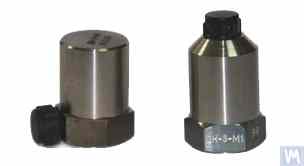
ਚਿੱਤਰ 4.1. ਪਾਈਜ਼ੋ ਐਕਸਲੇਰੋਮੀਟਰ DN 3M1 ਅਤੇ DN 3M1V6
ਅਜਿਹੇ ਸੈਂਸਰਾਂ ਨੂੰ ਵਾਈਬ੍ਰੇਸ਼ਨ ਮਾਪਣ ਵਾਲੇ ਯੰਤਰਾਂ ਅਤੇ ਸਿਸਟਮਾਂ ਨਾਲ ਜੋੜਨ ਲਈ, ਬਾਹਰੀ ਜਾਂ ਬਿਲਟ-ਇਨ ਚਾਰਜ ਐਂਪਲੀਫਾਇਰ ਵਰਤਣੇ ਜ਼ਰੂਰੀ ਹਨ।
ਚਿੱਤਰ 4.2। LLC "Kinematics" (Vibromera) ਦੁਆਰਾ ਬਣਾਏ AD1 ਕੈਪੇਸਿਟਿਵ ਐਕਸੀਲਰੋਮੀਟਰ
ਇਹ ਧਿਆਨ ਦੇਣ ਯੋਗ ਹੈ ਕਿ ਇਹਨਾਂ ਸੈਂਸਰਾਂ ਵਿੱਚ, ਜਿਹਨਾਂ ਵਿੱਚ ਵਿਆਪਕ ਤੌਰ 'ਤੇ ਵਰਤੇ ਜਾਂਦੇ ਮਾਰਕੀਟ ਬੋਰਡ ਕੈਪੇਸਿਟਿਵ ਐਕਸਲੇਰੋਮੀਟਰ ADXL 345 (ਚਿੱਤਰ 4.3 ਦੇਖੋ) ਸ਼ਾਮਲ ਹਨ, ਪਾਈਜ਼ੋ ਐਕਸਲੇਰੋਮੀਟਰਾਂ ਦੇ ਮੁਕਾਬਲੇ ਕਈ ਮਹੱਤਵਪੂਰਨ ਫਾਇਦੇ ਹਨ। ਖਾਸ ਤੌਰ 'ਤੇ, ਇਹ ਸਮਾਨ ਤਕਨੀਕੀ ਵਿਸ਼ੇਸ਼ਤਾਵਾਂ ਦੇ ਨਾਲ 4 ਤੋਂ 8 ਗੁਣਾ ਸਸਤੇ ਹਨ। ਇਸ ਤੋਂ ਇਲਾਵਾ, ਇਹਨਾਂ ਨੂੰ ਪਾਈਜ਼ੋ ਐਕਸਲੇਰੋਮੀਟਰਾਂ ਲਈ ਲੋੜੀਂਦੇ ਮਹਿੰਗੇ ਅਤੇ ਨਾਜ਼ੁਕ ਚਾਰਜ ਐਂਪਲੀਫਾਇਰਾਂ ਦੀ ਲੋੜ ਨਹੀਂ ਹੈ।
ਜਿਨ੍ਹਾਂ ਮਾਮਲਿਆਂ ਵਿੱਚ ਬੈਲੈਂਸਿੰਗ ਮਸ਼ੀਨਾਂ ਦੇ ਮਾਪਣ ਸਿਸਟਮਾਂ ਵਿੱਚ ਦੋਵੇਂ ਕਿਸਮਾਂ ਦੇ ਐਕਸਲੇਰੋਮੀਟਰ ਵਰਤੇ ਜਾਂਦੇ ਹਨ, ਸੈਂਸਰ ਸਿਗਨਲਾਂ ਦਾ ਹਾਰਡਵੇਅਰ ਇੰਟੀਗ੍ਰੇਸ਼ਨ (ਜਾਂ ਡਬਲ ਇੰਟੀਗ੍ਰੇਸ਼ਨ) ਆਮ ਤੌਰ 'ਤੇ ਕੀਤਾ ਜਾਂਦਾ ਹੈ।
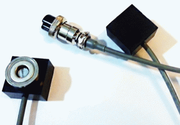
ਚਿੱਤਰ 4.2. ਕੈਪੇਸਿਟਿਵ ਐਕਸਲੇਰੋਮੀਟਰ AD 1, ਅਸੈਂਬਲਡ।
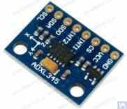
ਚਿੱਤਰ 4.3. ਕੈਪੇਸਿਟਿਵ ਐਕਸਲੇਰੋਮੀਟਰ ਬੋਰਡ ADXL 345।
ਇਸ ਮਾਮਲੇ ਵਿੱਚ, ਸ਼ੁਰੂਆਤੀ ਸੈਂਸਰ ਸਿਗਨਲ, ਜੋ ਵਾਈਬ੍ਰੇਸ਼ਨਲ ਪ੍ਰਵੇਗ ਦੇ ਅਨੁਪਾਤਕ ਹੁੰਦਾ ਹੈ, ਉਸ ਅਨੁਸਾਰ ਵਾਈਬ੍ਰੇਸ਼ਨਲ ਵੇਗ ਜਾਂ ਵਿਸਥਾਪਨ ਦੇ ਅਨੁਪਾਤਕ ਸਿਗਨਲ ਵਿੱਚ ਬਦਲਿਆ ਜਾਂਦਾ ਹੈ। ਵਾਈਬ੍ਰੇਸ਼ਨ ਸਿਗਨਲ ਦੇ ਡਬਲ ਇੰਟੀਗ੍ਰੇਸ਼ਨ ਦੀ ਪ੍ਰਕਿਰਿਆ ਖਾਸ ਤੌਰ 'ਤੇ ਉਦੋਂ ਢੁਕਵੀਂ ਹੁੰਦੀ ਹੈ ਜਦੋਂ ਘੱਟ-ਸਪੀਡ ਬੈਲੈਂਸਿੰਗ ਮਸ਼ੀਨਾਂ ਦੇ ਮਾਪਣ ਸਿਸਟਮਾਂ ਦੇ ਹਿੱਸੇ ਵਜੋਂ ਐਕਸਲੇਰੋਮੀਟਰ ਵਰਤੇ ਜਾਂਦੇ ਹਨ, ਜਿੱਥੇ ਬੈਲੈਂਸਿੰਗ ਦੌਰਾਨ ਹੇਠਲੀ ਰੋਟਰ ਘੁੰਮਣ ਫ੍ਰੀਕੁਐਂਸੀ ਰੇਂਜ 120 rpm ਅਤੇ ਇਸ ਤੋਂ ਹੇਠਾਂ ਤੱਕ ਪਹੁੰਚ ਸਕਦੀ ਹੈ। ਬੈਲੈਂਸਿੰਗ ਮਸ਼ੀਨਾਂ ਦੇ ਮਾਪਣ ਸਿਸਟਮਾਂ ਵਿੱਚ ਕੈਪੇਸਿਟਿਵ ਐਕਸਲੇਰੋਮੀਟਰ ਵਰਤਦੇ ਸਮੇਂ, ਇਹ ਧਿਆਨ ਵਿੱਚ ਰੱਖਣਾ ਚਾਹੀਦਾ ਹੈ ਕਿ ਇੰਟੀਗ੍ਰੇਸ਼ਨ ਤੋਂ ਬਾਅਦ, ਇਹਨਾਂ ਦੇ ਸਿਗਨਲਾਂ ਵਿੱਚ 0.5 ਤੋਂ 3 Hz ਦੀ ਫ੍ਰੀਕੁਐਂਸੀ ਰੇਂਜ ਵਿੱਚ ਪ੍ਰਗਟ ਹੋਣ ਵਾਲੀ ਘੱਟ-ਫ੍ਰੀਕੁਐਂਸੀ ਦਖ਼ਲਅੰਦਾਜ਼ੀ ਹੋ ਸਕਦੀ ਹੈ। ਇਹ ਇਹਨਾਂ ਸੈਂਸਰਾਂ ਦੀ ਵਰਤੋਂ ਕਰਨ ਵਾਲੀਆਂ ਮਸ਼ੀਨਾਂ 'ਤੇ ਬੈਲੈਂਸਿੰਗ ਦੀ ਹੇਠਲੀ ਫ੍ਰੀਕੁਐਂਸੀ ਰੇਂਜ ਨੂੰ ਸੀਮਿਤ ਕਰ ਸਕਦਾ ਹੈ।
4.1.2. ਵਾਈਬ੍ਰੇਸ਼ਨ ਵੇਗ ਸੈਂਸਰ
4.1.2.1. ਇੰਡਕਟਿਵ ਵਾਈਬ੍ਰੇਸ਼ਨ ਵੇਗ ਸੈਂਸਰ।
ਇਹਨਾਂ ਸੈਂਸਰਾਂ ਵਿੱਚ ਇੱਕ ਇੰਡਕਟਿਵ ਕੋਇਲ ਅਤੇ ਇੱਕ ਮੈਗਨੈਟਿਕ ਕੋਰ ਸ਼ਾਮਲ ਹੁੰਦਾ ਹੈ। ਜਦੋਂ ਕੋਇਲ ਇੱਕ ਸਥਿਰ ਕੋਰ ਦੇ ਸਾਪੇਖ (ਜਾਂ ਕੋਰ ਇੱਕ ਸਥਿਰ ਕੋਇਲ ਦੇ ਸਾਪੇਖ) ਵਾਈਬ੍ਰੇਟ ਕਰਦਾ ਹੈ, ਤਾਂ ਕੋਇਲ ਵਿੱਚ ਇੱਕ EMF ਪ੍ਰੇਰਿਤ ਹੁੰਦਾ ਹੈ, ਜਿਸ ਦੀ ਵੋਲਟੇਜ ਸੈਂਸਰ ਦੇ ਚੱਲਣਯੋਗ ਤੱਤ ਦੀ ਵਾਈਬ੍ਰੇਸ਼ਨ ਵੇਗ ਦੇ ਸਿੱਧੇ ਅਨੁਪਾਤਕ ਹੁੰਦੀ ਹੈ। ਇੰਡਕਟਿਵ ਸੈਂਸਰਾਂ ਦੇ ਪਰਿਵਰਤਨ ਗੁਣਾਂਕ (Кпр) ਆਮ ਤੌਰ 'ਤੇ ਕਾਫ਼ੀ ਉੱਚੇ ਹੁੰਦੇ ਹਨ, ਜੋ ਕਈ ਦਹਾਈਆਂ ਜਾਂ ਸੈਂਕੜੇ mV/mm/sec ਤੱਕ ਪਹੁੰਚਦੇ ਹਨ। ਖਾਸ ਤੌਰ 'ਤੇ, Schenck ਮਾਡਲ T77 ਸੈਂਸਰ ਦਾ ਪਰਿਵਰਤਨ ਗੁਣਾਂਕ 80 mV/mm/sec ਹੈ, ਅਤੇ IRD Mechanalysis ਮਾਡਲ 544M ਸੈਂਸਰ ਲਈ ਇਹ 40 mV/mm/sec ਹੈ। ਕੁਝ ਮਾਮਲਿਆਂ ਵਿੱਚ (ਉਦਾਹਰਨ ਲਈ, Schenck ਬੈਲੈਂਸਿੰਗ ਮਸ਼ੀਨਾਂ ਵਿੱਚ), ਮਕੈਨੀਕਲ ਐਂਪਲੀਫਾਇਰ ਵਾਲੇ ਵਿਸ਼ੇਸ਼ ਉੱਚ-ਸੰਵੇਦਨਸ਼ੀਲ ਇੰਡਕਟਿਵ ਵਾਈਬ੍ਰੇਸ਼ਨ ਵੇਗ ਸੈਂਸਰ ਵਰਤੇ ਜਾਂਦੇ ਹਨ, ਜਿੱਥੇ Кпр 1000 mV/mm/sec ਤੋਂ ਵੱਧ ਹੋ ਸਕਦਾ ਹੈ। ਜੇਕਰ ਬੈਲੈਂਸਿੰਗ ਮਸ਼ੀਨਾਂ ਦੇ ਮਾਪਣ ਸਿਸਟਮਾਂ ਵਿੱਚ ਇੰਡਕਟਿਵ ਵਾਈਬ੍ਰੇਸ਼ਨ ਵੇਗ ਸੈਂਸਰ ਵਰਤੇ ਜਾਂਦੇ ਹਨ, ਤਾਂ ਵਾਈਬ੍ਰੇਸ਼ਨ ਵੇਗ ਦੇ ਅਨੁਪਾਤਕ ਬਿਜਲੀ ਸਿਗਨਲ ਦਾ ਹਾਰਡਵੇਅਰ ਇੰਟੀਗ੍ਰੇਸ਼ਨ ਵੀ ਕੀਤਾ ਜਾ ਸਕਦਾ ਹੈ, ਜੋ ਇਸ ਨੂੰ ਵਾਈਬ੍ਰੇਸ਼ਨ ਵਿਸਥਾਪਨ ਦੇ ਅਨੁਪਾਤਕ ਸਿਗਨਲ ਵਿੱਚ ਬਦਲਦਾ ਹੈ।
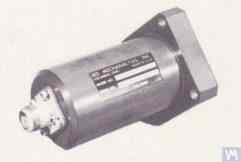
ਚਿੱਤਰ 4.4. IRD Mechanalysis ਦਾ ਮਾਡਲ 544M ਸੈਂਸਰ।
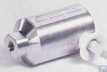
ਚਿੱਤਰ 4.5. Schenck ਦਾ ਮਾਡਲ T77 ਸੈਂਸਰ
ਇਹ ਧਿਆਨ ਦੇਣ ਯੋਗ ਹੈ ਕਿ ਉਹਨਾਂ ਦੇ ਉਤਪਾਦਨ ਦੀ ਮਿਹਨਤ-ਪ੍ਰਧਾਨ ਪ੍ਰਕਿਰਿਆ ਕਾਰਨ, ਇੰਡਕਟਿਵ ਵਾਈਬ੍ਰੇਸ਼ਨ ਵੇਗ ਸੈਂਸਰ ਕਾਫ਼ੀ ਦੁਰਲੱਭ ਅਤੇ ਮਹਿੰਗੀਆਂ ਵਸਤਾਂ ਹਨ। ਇਸ ਲਈ, ਇਹਨਾਂ ਸੈਂਸਰਾਂ ਦੇ ਸਪੱਸ਼ਟ ਫਾਇਦਿਆਂ ਦੇ ਬਾਵਜੂਦ, ਬੈਲੈਂਸਿੰਗ ਮਸ਼ੀਨਾਂ ਦੇ ਸ਼ੌਕੀਨ ਨਿਰਮਾਤਾ ਇਹਨਾਂ ਨੂੰ ਬਹੁਤ ਘੱਟ ਹੀ ਵਰਤਦੇ ਹਨ।
4.2. ਫੇਜ਼ ਐਂਗਲ ਸੈਂਸਰ
ਬੈਲੈਂਸ ਕੀਤੇ ਜਾ ਰਹੇ ਰੋਟਰ ਦੇ ਰੋਟੇਸ਼ਨ ਐਂਗਲ ਨਾਲ ਵਾਈਬ੍ਰੇਸ਼ਨ ਮਾਪ ਪ੍ਰਕਿਰਿਆ ਨੂੰ ਸਿੰਕ੍ਰੋਨਾਈਜ਼ ਕਰਨ ਲਈ, ਫੇਜ਼ ਐਂਗਲ ਸੈਂਸਰ, ਜਿਵੇਂ ਕਿ ਲੇਜ਼ਰ (ਫੋਟੋਇਲੈਕਟ੍ਰਿਕ) ਜਾਂ ਇੰਡਕਟਿਵ ਸੈਂਸਰ, ਵਰਤੇ ਜਾਂਦੇ ਹਨ। ਇਹ ਸੈਂਸਰ ਘਰੇਲੂ ਅਤੇ ਅੰਤਰਰਾਸ਼ਟਰੀ ਦੋਵੇਂ ਨਿਰਮਾਤਾਵਾਂ ਦੁਆਰਾ ਵੱਖ-ਵੱਖ ਡਿਜ਼ਾਈਨਾਂ ਵਿੱਚ ਬਣਾਏ ਜਾਂਦੇ ਹਨ। ਇਹਨਾਂ ਸੈਂਸਰਾਂ ਦੀ ਕੀਮਤ ਰੇਂਜ ਲਗਭਗ 40 ਤੋਂ 200 ਡਾਲਰ ਤੱਕ ਕਾਫ਼ੀ ਵੱਖ-ਵੱਖ ਹੋ ਸਕਦੀ ਹੈ। ਅਜਿਹੇ ਯੰਤਰ ਦੀ ਇੱਕ ਉਦਾਹਰਨ "Diamex" ਦੁਆਰਾ ਬਣਾਇਆ ਫੇਜ਼ ਐਂਗਲ ਸੈਂਸਰ ਹੈ, ਜੋ ਚਿੱਤਰ 4.11 ਵਿੱਚ ਦਿਖਾਇਆ ਗਿਆ ਹੈ।
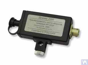
ਚਿੱਤਰ 4.11: "Diamex" ਦਾ ਫੇਜ਼ ਐਂਗਲ ਸੈਂਸਰ
ਇੱਕ ਹੋਰ ਉਦਾਹਰਨ ਵਜੋਂ, ਚਿੱਤਰ 4.12 LLC "Kinematics" (Vibromera) ਦੁਆਰਾ ਲਾਗੂ ਕੀਤਾ ਗਿਆ ਇੱਕ ਮਾਡਲ ਦਿਖਾਉਂਦਾ ਹੈ, ਜੋ ਚੀਨ ਵਿੱਚ ਬਣੇ DT 2234C ਮਾਡਲ ਦੇ ਲੇਜ਼ਰ ਟੈਕੋਮੀਟਰਾਂ ਨੂੰ ਫੇਜ਼ ਐਂਗਲ ਸੈਂਸਰਾਂ ਵਜੋਂ ਵਰਤਦਾ ਹੈ। ਇਸ ਸੈਂਸਰ ਦੇ ਸਪੱਸ਼ਟ ਫਾਇਦਿਆਂ ਵਿੱਚ ਸ਼ਾਮਲ ਹਨ:
- ਇੱਕ ਵਿਸ਼ਾਲ ਸੰਚਾਲਨ ਰੇਂਜ, ਜੋ 2.5 ਤੋਂ 99,999 ਘੁੰਮਣ ਪ੍ਰਤੀ ਮਿੰਟ ਤੱਕ ਰੋਟਰ ਘੁੰਮਣ ਫ੍ਰੀਕੁਐਂਸੀ ਦੇ ਮਾਪ ਦੀ ਆਗਿਆ ਦਿੰਦੀ ਹੈ, ਘੱਟੋ-ਘੱਟ ਇੱਕ ਘੁੰਮਣ ਦੇ ਰੈਜ਼ੋਲਿਊਸ਼ਨ ਨਾਲ;
- ਡਿਜੀਟਲ ਡਿਸਪਲੇ;
- ਮਾਪਾਂ ਲਈ ਟੈਕੋਮੀਟਰ ਸੈੱਟ ਕਰਨ ਦੀ ਸੌਖ;
- ਸਸਤਾਪਣ ਅਤੇ ਘੱਟ ਮਾਰਕੀਟ ਲਾਗਤ;
- ਬੈਲੈਂਸਿੰਗ ਮਸ਼ੀਨ ਦੇ ਮਾਪਣ ਸਿਸਟਮ ਵਿੱਚ ਏਕੀਕਰਨ ਲਈ ਸੋਧ ਦੀ ਅਪੇਖਿਕ ਸਾਦਗੀ।
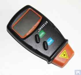
ਚਿੱਤਰ 4.12: ਲੇਜ਼ਰ ਟੈਕੋਮੀਟਰ ਮਾਡਲ DT 2234C
ਕੁਝ ਮਾਮਲਿਆਂ ਵਿੱਚ, ਜਦੋਂ ਕਿਸੇ ਕਾਰਨ ਆਪਟੀਕਲ ਲੇਜ਼ਰ ਸੈਂਸਰਾਂ ਦੀ ਵਰਤੋਂ ਅਣਚਾਹੀ ਹੁੰਦੀ ਹੈ, ਤਾਂ ਇਹਨਾਂ ਨੂੰ ਇੰਡਕਟਿਵ ਨਾਨ-ਕਾਂਟੈਕਟ ਵਿਸਥਾਪਨ ਸੈਂਸਰਾਂ ਨਾਲ ਬਦਲਿਆ ਜਾ ਸਕਦਾ ਹੈ, ਜਿਵੇਂ ਕਿ ਪਹਿਲਾਂ ਦੱਸਿਆ ਗਿਆ ISAN E41A ਮਾਡਲ ਜਾਂ ਹੋਰ ਨਿਰਮਾਤਾਵਾਂ ਦੇ ਸਮਾਨ ਉਤਪਾਦ।
4.3. ਵਾਈਬ੍ਰੇਸ਼ਨ ਸੈਂਸਰਾਂ ਵਿੱਚ ਸਿਗਨਲ ਪ੍ਰੋਸੈਸਿੰਗ ਵਿਸ਼ੇਸ਼ਤਾਵਾਂ
ਬੈਲੈਂਸਿੰਗ ਉਪਕਰਣਾਂ ਵਿੱਚ ਵਾਈਬ੍ਰੇਸ਼ਨ ਸਿਗਨਲ ਦੇ ਘੁੰਮਣ ਵਾਲੇ ਹਿੱਸੇ ਦੇ ਐਪਲੀਟਿਊਡ ਅਤੇ ਫੇਜ਼ ਦੇ ਸਟੀਕ ਮਾਪ ਲਈ, ਹਾਰਡਵੇਅਰ ਅਤੇ ਸਾਫਟਵੇਅਰ ਪ੍ਰੋਸੈਸਿੰਗ ਟੂਲਾਂ ਦਾ ਸੁਮੇਲ ਆਮ ਤੌਰ 'ਤੇ ਵਰਤਿਆ ਜਾਂਦਾ ਹੈ। ਇਹ ਟੂਲ ਸਮਰੱਥ ਬਣਾਉਂਦੇ ਹਨ:
- ਸੈਂਸਰ ਦੇ ਐਨਾਲਾਗ ਸਿਗਨਲ ਦੀ ਬ੍ਰਾਡਬੈਂਡ ਹਾਰਡਵੇਅਰ ਫਿਲਟਰਿੰਗ;
- ਸੈਂਸਰ ਦੇ ਐਨਾਲਾਗ ਸਿਗਨਲ ਦਾ ਐਂਪਲੀਫਿਕੇਸ਼ਨ;
- ਐਨਾਲਾਗ ਸਿਗਨਲ ਦਾ ਇੰਟੀਗ੍ਰੇਸ਼ਨ ਅਤੇ/ਜਾਂ ਡਬਲ ਇੰਟੀਗ੍ਰੇਸ਼ਨ (ਜੇ ਲੋੜ ਹੋਵੇ);
- ਟ੍ਰੈਕਿੰਗ ਫਿਲਟਰ ਦੀ ਵਰਤੋਂ ਕਰਕੇ ਐਨਾਲਾਗ ਸਿਗਨਲ ਦੀ ਨੈਰੋਬੈਂਡ ਫਿਲਟਰਿੰਗ;
- ਸਿਗਨਲ ਦਾ ਐਨਾਲਾਗ-ਟੂ-ਡਿਜੀਟਲ ਪਰਿਵਰਤਨ;
- ਡਿਜੀਟਲ ਸਿਗਨਲ ਦੀ ਸਿੰਕ੍ਰੋਨਸ ਫਿਲਟਰਿੰਗ;
- ਡਿਜੀਟਲ ਸਿਗਨਲ ਦਾ ਹਾਰਮੋਨਿਕ ਵਿਸ਼ਲੇਸ਼ਣ।
4.3.1. ਬ੍ਰੌਡਬੈਂਡ ਸਿਗਨਲ ਫਿਲਟਰਿੰਗ
ਇਹ ਪ੍ਰਕਿਰਿਆ ਵਾਈਬ੍ਰੇਸ਼ਨ ਸੈਂਸਰ ਸਿਗਨਲ ਨੂੰ ਸੰਭਾਵੀ ਦਖਲਅੰਦਾਜ਼ੀ ਤੋਂ ਸਾਫ਼ ਕਰਨ ਲਈ ਜ਼ਰੂਰੀ ਹੈ, ਜੋ ਯੰਤਰ ਦੀ ਫ੍ਰੀਕੁਐਂਸੀ ਰੇਂਜ ਦੀਆਂ ਹੇਠਲੀਆਂ ਅਤੇ ਉੱਪਰਲੀਆਂ ਦੋਵੇਂ ਸੀਮਾਵਾਂ 'ਤੇ ਹੋ ਸਕਦੀ ਹੈ। ਬੈਲੈਂਸਿੰਗ ਮਸ਼ੀਨ ਦੇ ਮਾਪਣ ਯੰਤਰ ਲਈ ਬੈਂਡ-ਪਾਸ ਫਿਲਟਰ ਦੀ ਹੇਠਲੀ ਸੀਮਾ 2-3 Hz ਅਤੇ ਉੱਪਰਲੀ ਸੀਮਾ 50 (100) Hz 'ਤੇ ਸੈੱਟ ਕਰਨੀ ਸਲਾਹਯੋਗ ਹੈ। "ਹੇਠਲੀ" ਫਿਲਟਰਿੰਗ ਵੱਖ-ਵੱਖ ਕਿਸਮ ਦੇ ਸੈਂਸਰ ਮਾਪ ਐਂਪਲੀਫਾਇਰਾਂ ਦੇ ਆਊਟਪੁੱਟ 'ਤੇ ਦਿਖਾਈ ਦੇਣ ਵਾਲੇ ਘੱਟ-ਫ੍ਰੀਕੁਐਂਸੀ ਸ਼ੋਰਾਂ ਨੂੰ ਦਬਾਉਣ ਵਿੱਚ ਮਦਦ ਕਰਦੀ ਹੈ। "ਉੱਪਰਲੀ" ਫਿਲਟਰਿੰਗ ਸੰਯੋਜਨ ਫ੍ਰੀਕੁਐਂਸੀਆਂ ਅਤੇ ਮਸ਼ੀਨ ਦੇ ਵਿਅਕਤੀਗਤ ਮਕੈਨੀਕਲ ਕੰਪੋਨੈਂਟਾਂ ਦੀਆਂ ਸੰਭਾਵੀ ਰੈਜ਼ੋਨੈਂਟ ਵਾਈਬ੍ਰੇਸ਼ਨਾਂ ਕਾਰਨ ਹੋਣ ਵਾਲੀ ਦਖਲਅੰਦਾਜ਼ੀ ਦੀ ਸੰਭਾਵਨਾ ਨੂੰ ਖ਼ਤਮ ਕਰਦੀ ਹੈ।
4.3.2. ਸੈਂਸਰ ਤੋਂ ਐਨਾਲਾਗ ਸਿਗਨਲ ਦਾ ਐਂਪਲੀਫਿਕੇਸ਼ਨ
ਜੇਕਰ ਬੈਲੈਂਸਿੰਗ ਮਸ਼ੀਨ ਦੀ ਮਾਪਣ ਪ੍ਰਣਾਲੀ ਦੀ ਸੰਵੇਦਨਸ਼ੀਲਤਾ ਵਧਾਉਣ ਦੀ ਲੋੜ ਹੋਵੇ, ਤਾਂ ਵਾਈਬ੍ਰੇਸ਼ਨ ਸੈਂਸਰਾਂ ਤੋਂ ਮਾਪਣ ਯੂਨਿਟ ਦੇ ਇਨਪੁੱਟ ਤੱਕ ਦੇ ਸਿਗਨਲਾਂ ਨੂੰ ਐਂਪਲੀਫਾਈ ਕੀਤਾ ਜਾ ਸਕਦਾ ਹੈ। ਸਥਿਰ ਗੇਨ ਵਾਲੇ ਸਟੈਂਡਰਡ ਐਂਪਲੀਫਾਇਰ ਅਤੇ ਮਲਟੀਸਟੇਜ ਐਂਪਲੀਫਾਇਰ, ਜਿਨ੍ਹਾਂ ਦਾ ਗੇਨ ਸੈਂਸਰ ਤੋਂ ਅਸਲ ਸਿਗਨਲ ਪੱਧਰ 'ਤੇ ਨਿਰਭਰ ਕਰਦੇ ਹੋਏ ਪ੍ਰੋਗਰਾਮੈਟਿਕ ਤੌਰ 'ਤੇ ਬਦਲਿਆ ਜਾ ਸਕਦਾ ਹੈ, ਦੋਵੇਂ ਵਰਤੇ ਜਾ ਸਕਦੇ ਹਨ। ਪ੍ਰੋਗਰਾਮੇਬਲ ਮਲਟੀਸਟੇਜ ਐਂਪਲੀਫਾਇਰ ਦੀ ਇੱਕ ਉਦਾਹਰਨ ਵਿੱਚ LLC "L-Card" ਦੁਆਰਾ E154 ਜਾਂ E14-140 ਵਰਗੇ ਵੋਲਟੇਜ ਮਾਪ ਕਨਵਰਟਰਾਂ ਵਿੱਚ ਲਾਗੂ ਕੀਤੇ ਐਂਪਲੀਫਾਇਰ ਸ਼ਾਮਲ ਹਨ।
4.3.3. ਇੰਟੀਗ੍ਰੇਸ਼ਨ
ਜਿਵੇਂ ਪਹਿਲਾਂ ਦੱਸਿਆ ਗਿਆ ਹੈ, ਬੈਲੇਂਸਿੰਗ ਮਸ਼ੀਨਾਂ ਦੇ ਮਾਪਣ ਪ੍ਰਣਾਲੀਆਂ ਵਿੱਚ ਵਾਈਬ੍ਰੇਸ਼ਨ ਸੈਂਸਰ ਸਿਗਨਲਾਂ ਦਾ ਹਾਰਡਵੇਅਰ ਇੰਟੀਗ੍ਰੇਸ਼ਨ ਅਤੇ/ਜਾਂ ਡਬਲ ਇੰਟੀਗ੍ਰੇਸ਼ਨ ਸਿਫ਼ਾਰਸ਼ ਕੀਤਾ ਜਾਂਦਾ ਹੈ। ਇਸ ਤਰ੍ਹਾਂ, ਵਾਈਬ੍ਰੋ-ਐਕਸਲਰੇਸ਼ਨ ਦੇ ਅਨੁਪਾਤੀ ਸ਼ੁਰੂਆਤੀ ਐਕਸਲਰੋਮੀਟਰ ਸਿਗਨਲ ਨੂੰ ਵਾਈਬ੍ਰੋ-ਸਪੀਡ (ਇੰਟੀਗ੍ਰੇਸ਼ਨ) ਜਾਂ ਵਾਈਬ੍ਰੋ-ਡਿਸਪਲੇਸਮੈਂਟ (ਡਬਲ ਇੰਟੀਗ੍ਰੇਸ਼ਨ) ਦੇ ਅਨੁਪਾਤੀ ਸਿਗਨਲ ਵਿੱਚ ਬਦਲਿਆ ਜਾ ਸਕਦਾ ਹੈ। ਇਸੇ ਤਰ੍ਹਾਂ, ਵਾਈਬ੍ਰੋ-ਸਪੀਡ ਸੈਂਸਰ ਸਿਗਨਲ ਨੂੰ ਇੰਟੀਗ੍ਰੇਸ਼ਨ ਤੋਂ ਬਾਅਦ ਵਾਈਬ੍ਰੋ-ਡਿਸਪਲੇਸਮੈਂਟ ਦੇ ਅਨੁਪਾਤੀ ਸਿਗਨਲ ਵਿੱਚ ਬਦਲਿਆ ਜਾ ਸਕਦਾ ਹੈ।
4.3.4. ਟਰੈਕਿੰਗ ਫਿਲਟਰ ਦੀ ਵਰਤੋਂ ਕਰਕੇ ਐਨਾਲਾਗ ਸਿਗਨਲ ਦੀ ਨੈਰੋਬੈਂਡ ਫਿਲਟਰਿੰਗ
ਬੈਲੈਂਸਿੰਗ ਮਸ਼ੀਨਾਂ ਦੀਆਂ ਮਾਪਣ ਪ੍ਰਣਾਲੀਆਂ ਵਿੱਚ ਦਖਲਅੰਦਾਜ਼ੀ ਘਟਾਉਣ ਅਤੇ ਵਾਈਬ੍ਰੇਸ਼ਨ ਸਿਗਨਲ ਪ੍ਰੋਸੈਸਿੰਗ ਦੀ ਗੁਣਵੱਤਾ ਸੁਧਾਰਨ ਲਈ, ਨੈਰੋਬੈਂਡ ਟਰੈਕਿੰਗ ਫਿਲਟਰ ਵਰਤੇ ਜਾ ਸਕਦੇ ਹਨ। ਇਹਨਾਂ ਫਿਲਟਰਾਂ ਦੀ ਕੇਂਦਰੀ ਫ੍ਰੀਕੁਐਂਸੀ ਰੋਟਰ ਦੇ ਰੈਵੋਲਿਊਸ਼ਨ ਸੈਂਸਰ ਸਿਗਨਲ ਦੀ ਵਰਤੋਂ ਕਰਦੇ ਹੋਏ ਬੈਲੈਂਸ ਕੀਤੇ ਜਾ ਰਹੇ ਰੋਟਰ ਦੀ ਰੋਟੇਸ਼ਨ ਫ੍ਰੀਕੁਐਂਸੀ ਨਾਲ ਆਟੋਮੈਟਿਕ ਤੌਰ 'ਤੇ ਟਿਊਨ ਹੁੰਦੀ ਹੈ। ਅਜਿਹੇ ਫਿਲਟਰ ਬਣਾਉਣ ਲਈ "MAXIM" ਦੇ MAX263, MAX264, MAX267, MAX268 ਵਰਗੇ ਆਧੁਨਿਕ ਇੰਟੀਗ੍ਰੇਟਿਡ ਸਰਕਟਾਂ ਦੀ ਵਰਤੋਂ ਕੀਤੀ ਜਾ ਸਕਦੀ ਹੈ।
4.3.5. ਸਿਗਨਲਾਂ ਦਾ ਐਨਾਲਾਗ-ਟੂ-ਡਿਜੀਟਲ ਕਨਵਰਜ਼ਨ
ਐਨਾਲਾਗ-ਟੂ-ਡਿਜੀਟਲ ਕਨਵਰਜ਼ਨ ਇੱਕ ਮਹੱਤਵਪੂਰਨ ਪ੍ਰਕਿਰਿਆ ਹੈ ਜੋ ਐਂਪਲੀਟਿਊਡ ਅਤੇ ਫੇਜ਼ ਦੇ ਮਾਪ ਦੌਰਾਨ ਵਾਈਬ੍ਰੇਸ਼ਨ ਸਿਗਨਲ ਪ੍ਰੋਸੈਸਿੰਗ ਦੀ ਗੁਣਵੱਤਾ ਸੁਧਾਰਨ ਦੀ ਸੰਭਾਵਨਾ ਯਕੀਨੀ ਬਣਾਉਂਦੀ ਹੈ। ਇਹ ਪ੍ਰਕਿਰਿਆ ਬੈਲੈਂਸਿੰਗ ਮਸ਼ੀਨਾਂ ਦੀਆਂ ਸਾਰੀਆਂ ਆਧੁਨਿਕ ਮਾਪਣ ਪ੍ਰਣਾਲੀਆਂ ਵਿੱਚ ਲਾਗੂ ਕੀਤੀ ਜਾਂਦੀ ਹੈ। ਅਜਿਹੇ ADC ਦੇ ਪ੍ਰਭਾਵਸ਼ਾਲੀ ਲਾਗੂਕਰਨ ਦੀ ਇੱਕ ਉਦਾਹਰਨ ਵਿੱਚ LLC "L-Card" ਦੁਆਰਾ E154 ਜਾਂ E14-140 ਕਿਸਮ ਦੇ ਵੋਲਟੇਜ ਮਾਪ ਕਨਵਰਟਰ ਸ਼ਾਮਲ ਹਨ, ਜੋ LLC "Kinematics" (Vibromera) ਦੁਆਰਾ ਬਣਾਈਆਂ ਗਈਆਂ ਕਈ ਬੈਲੈਂਸਿੰਗ ਮਸ਼ੀਨ ਮਾਪਣ ਪ੍ਰਣਾਲੀਆਂ ਵਿੱਚ ਵਰਤੇ ਜਾਂਦੇ ਹਨ। ਇਸ ਤੋਂ ਇਲਾਵਾ, LLC "Kinematics" (Vibromera) ਨੂੰ "Arduino" ਕੰਟਰੋਲਰਾਂ, "Microchip" ਦੇ PIC18F4620 ਮਾਈਕ੍ਰੋਕੰਟਰੋਲਰ, ਅਤੇ ਸਮਾਨ ਯੰਤਰਾਂ 'ਤੇ ਅਧਾਰਿਤ ਸਸਤੀਆਂ ਮਾਈਕ੍ਰੋਪ੍ਰੋਸੈਸਰ ਪ੍ਰਣਾਲੀਆਂ ਦੀ ਵਰਤੋਂ ਕਰਨ ਦਾ ਤਜਰਬਾ ਵੀ ਹੈ।
4.1.2.2. ਪੀਜ਼ੋਇਲੈਕਟ੍ਰਿਕ ਐਕਸੀਲਰੋਮੀਟਰਾਂ 'ਤੇ ਅਧਾਰਿਤ ਵਾਈਬ੍ਰੇਸ਼ਨ ਵੈਲੋਸਿਟੀ ਸੈਂਸਰ
ਇਸ ਕਿਸਮ ਦਾ ਸੈਂਸਰ ਇੱਕ ਸਟੈਂਡਰਡ ਪੀਜ਼ੋਇਲੈਕਟ੍ਰਿਕ ਐਕਸੀਲਰੋਮੀਟਰ ਤੋਂ ਇਸ ਤਰ੍ਹਾਂ ਵੱਖਰਾ ਹੈ ਕਿ ਇਸਦੇ ਹਾਊਸਿੰਗ ਦੇ ਅੰਦਰ ਇੱਕ ਬਿਲਟ-ਇਨ ਚਾਰਜ ਐਂਪਲੀਫਾਇਰ ਅਤੇ ਇੰਟੀਗ੍ਰੇਟਰ ਹੁੰਦਾ ਹੈ, ਜੋ ਇਸਨੂੰ ਵਾਈਬ੍ਰੇਸ਼ਨ ਵੈਲੋਸਿਟੀ ਦੇ ਅਨੁਪਾਤਕ ਸਿਗਨਲ ਆਊਟਪੁੱਟ ਕਰਨ ਦੀ ਆਗਿਆ ਦਿੰਦਾ ਹੈ। ਉਦਾਹਰਨ ਵਜੋਂ, ਘਰੇਲੂ ਨਿਰਮਾਤਾਵਾਂ (ZETLAB ਕੰਪਨੀ ਅਤੇ LLC "Vibropribor") ਦੁਆਰਾ ਬਣਾਏ ਪੀਜ਼ੋਇਲੈਕਟ੍ਰਿਕ ਵਾਈਬ੍ਰੇਸ਼ਨ ਵੈਲੋਸਿਟੀ ਸੈਂਸਰ ਚਿੱਤਰ 4.6 ਅਤੇ 4.7 ਵਿੱਚ ਦਿਖਾਏ ਗਏ ਹਨ।
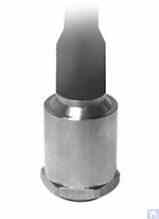
ਚਿੱਤਰ 4.6. ZETLAB (ਰੂਸ) ਦਾ ਮਾਡਲ AV02 ਸੈਂਸਰ
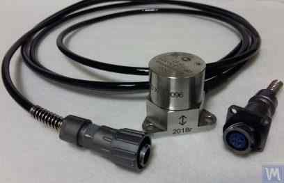
ਚਿੱਤਰ 4.7। LLC "Vibropribor" ਦਾ ਮਾਡਲ DVST 2 ਸੈਂਸਰ
ਅਜਿਹੇ ਸੈਂਸਰ ਵੱਖ-ਵੱਖ ਨਿਰਮਾਤਾਵਾਂ (ਦੇਸੀ ਅਤੇ ਵਿਦੇਸ਼ੀ ਦੋਵਾਂ) ਦੁਆਰਾ ਬਣਾਏ ਜਾਂਦੇ ਹਨ ਅਤੇ ਵਰਤਮਾਨ ਵਿੱਚ ਵਿਆਪਕ ਤੌਰ 'ਤੇ ਵਰਤੇ ਜਾਂਦੇ ਹਨ, ਖਾਸ ਕਰਕੇ ਪੋਰਟੇਬਲ ਵਾਈਬ੍ਰੇਸ਼ਨ ਉਪਕਰਣਾਂ ਵਿੱਚ। ਇਹਨਾਂ ਸੈਂਸਰਾਂ ਦੀ ਕੀਮਤ ਕਾਫ਼ੀ ਜ਼ਿਆਦਾ ਹੈ ਅਤੇ ਦੇਸੀ ਨਿਰਮਾਤਾਵਾਂ ਤੋਂ ਵੀ ਹਰੇਕ 20,000 ਤੋਂ 30,000 ਰੂਬਲ ਤੱਕ ਪਹੁੰਚ ਸਕਦੀ ਹੈ।
4.1.3. ਡਿਸਪਲੇਸਮੈਂਟ ਸੈਂਸਰ
ਬੈਲੈਂਸਿੰਗ ਮਸ਼ੀਨਾਂ ਦੀਆਂ ਮਾਪਣ ਪ੍ਰਣਾਲੀਆਂ ਵਿੱਚ, ਨਾਨ-ਕੰਟੈਕਟ ਡਿਸਪਲੇਸਮੈਂਟ ਸੈਂਸਰ – ਕੈਪੇਸਿਟਿਵ ਜਾਂ ਇੰਡਕਟਿਵ – ਵੀ ਵਰਤੇ ਜਾ ਸਕਦੇ ਹਨ। ਇਹ ਸੈਂਸਰ ਸਟੈਟਿਕ ਮੋਡ ਵਿੱਚ ਕੰਮ ਕਰ ਸਕਦੇ ਹਨ, ਜਿਸ ਨਾਲ 0 Hz ਤੋਂ ਸ਼ੁਰੂ ਹੋ ਕੇ ਵਾਈਬ੍ਰੇਸ਼ਨਲ ਪ੍ਰਕਿਰਿਆਵਾਂ ਦੀ ਰਿਕਾਰਡਿੰਗ ਸੰਭਵ ਹੁੰਦੀ ਹੈ। 120 rpm ਅਤੇ ਇਸ ਤੋਂ ਘੱਟ ਰੋਟੇਸ਼ਨ ਸਪੀਡ ਵਾਲੇ ਲੋ-ਸਪੀਡ ਰੋਟਰਾਂ ਨੂੰ ਬੈਲੈਂਸ ਕਰਨ ਦੇ ਮਾਮਲੇ ਵਿੱਚ ਇਹਨਾਂ ਦੀ ਵਰਤੋਂ ਖਾਸ ਤੌਰ 'ਤੇ ਪ੍ਰਭਾਵਸ਼ਾਲੀ ਹੋ ਸਕਦੀ ਹੈ। ਇਹਨਾਂ ਸੈਂਸਰਾਂ ਦੇ ਕਨਵਰਜ਼ਨ ਗੁਣਾਂਕ 1000 mV/mm ਅਤੇ ਇਸ ਤੋਂ ਵੱਧ ਤੱਕ ਪਹੁੰਚ ਸਕਦੇ ਹਨ, ਜੋ ਬਿਨਾਂ ਵਾਧੂ ਐਂਪਲੀਫਿਕੇਸ਼ਨ ਦੇ ਵੀ ਡਿਸਪਲੇਸਮੈਂਟ ਮਾਪ ਵਿੱਚ ਉੱਚ ਸ਼ੁੱਧਤਾ ਅਤੇ ਰੈਜ਼ੋਲਿਊਸ਼ਨ ਪ੍ਰਦਾਨ ਕਰਦੇ ਹਨ। ਇਹਨਾਂ ਸੈਂਸਰਾਂ ਦਾ ਇੱਕ ਸਪੱਸ਼ਟ ਫਾਇਦਾ ਉਹਨਾਂ ਦੀ ਮੁਕਾਬਲਤਨ ਘੱਟ ਲਾਗਤ ਹੈ, ਜੋ ਕੁਝ ਘਰੇਲੂ ਨਿਰਮਾਤਾਵਾਂ ਲਈ 1000 ਰੂਬਲ ਤੋਂ ਵੱਧ ਨਹੀਂ ਹੁੰਦੀ। ਬੈਲੈਂਸਿੰਗ ਮਸ਼ੀਨਾਂ ਵਿੱਚ ਇਹਨਾਂ ਸੈਂਸਰਾਂ ਦੀ ਵਰਤੋਂ ਕਰਦੇ ਸਮੇਂ, ਇਹ ਧਿਆਨ ਵਿੱਚ ਰੱਖਣਾ ਮਹੱਤਵਪੂਰਨ ਹੈ ਕਿ ਸੈਂਸਰ ਦੇ ਸੰਵੇਦਨਸ਼ੀਲ ਤੱਤ ਅਤੇ ਵਾਈਬ੍ਰੇਟਿੰਗ ਵਸਤੂ ਦੀ ਸਤਹ ਵਿਚਕਾਰ ਨਾਮਾਤਰ ਕਾਰਜਸ਼ੀਲ ਗੈਪ ਸੈਂਸਰ ਕੋਇਲ ਦੇ ਵਿਆਸ ਦੁਆਰਾ ਸੀਮਿਤ ਹੁੰਦਾ ਹੈ। ਉਦਾਹਰਨ ਵਜੋਂ, ਚਿੱਤਰ 4.8 ਵਿੱਚ ਦਿਖਾਏ ਗਏ "TEKO" ਦੇ ISAN E41A ਮਾਡਲ ਸੈਂਸਰ ਲਈ, ਨਿਰਧਾਰਿਤ ਕਾਰਜਸ਼ੀਲ ਗੈਪ ਆਮ ਤੌਰ 'ਤੇ 3.8 ਤੋਂ 4 mm ਹੁੰਦਾ ਹੈ, ਜੋ ਵਾਈਬ੍ਰੇਟਿੰਗ ਵਸਤੂ ਦੇ ਡਿਸਪਲੇਸਮੈਂਟ ਨੂੰ ±2.5 mm ਦੀ ਰੇਂਜ ਵਿੱਚ ਮਾਪਣ ਦੀ ਆਗਿਆ ਦਿੰਦਾ ਹੈ।
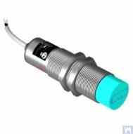
ਚਿੱਤਰ 4.8. TEKO (ਰੂਸ) ਦਾ ਇੰਡਕਟਿਵ ਡਿਸਪਲੇਸਮੈਂਟ ਸੈਂਸਰ ਮਾਡਲ ISAN E41A
4.1.4. ਫੋਰਸ ਸੈਂਸਰ
ਜਿਵੇਂ ਪਹਿਲਾਂ ਦੱਸਿਆ ਗਿਆ ਹੈ, ਫੋਰਸ ਸੈਂਸਰ ਹਾਰਡ ਬੇਅਰਿੰਗ ਬੈਲੇਂਸਿੰਗ ਮਸ਼ੀਨਾਂ 'ਤੇ ਲਗਾਏ ਗਏ ਮਾਪਣ ਪ੍ਰਣਾਲੀਆਂ ਵਿੱਚ ਵਰਤੇ ਜਾਂਦੇ ਹਨ। ਇਹ ਸੈਂਸਰ, ਖਾਸ ਕਰਕੇ ਆਪਣੀ ਨਿਰਮਾਣ ਦੀ ਸਾਦਗੀ ਅਤੇ ਮੁਕਾਬਲਤਨ ਘੱਟ ਲਾਗਤ ਕਾਰਨ, ਆਮ ਤੌਰ 'ਤੇ ਪੀਜ਼ੋਇਲੈਕਟ੍ਰਿਕ ਫੋਰਸ ਸੈਂਸਰ ਹੁੰਦੇ ਹਨ। ਅਜਿਹੇ ਸੈਂਸਰਾਂ ਦੀਆਂ ਉਦਾਹਰਣਾਂ ਚਿੱਤਰ 4.9 ਅਤੇ 4.10 ਵਿੱਚ ਦਿਖਾਈਆਂ ਗਈਆਂ ਹਨ।
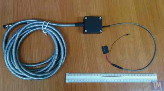
ਚਿੱਤਰ 4.9. Kinematika LLC ਦਾ ਫੋਰਸ ਸੈਂਸਰ SD 1
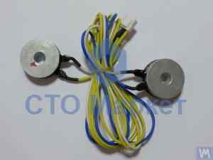
ਚਿੱਤਰ 4.10: "STO Market" ਦੁਆਰਾ ਵੇਚਿਆ ਗਿਆ ਆਟੋਮੋਟਿਵ ਬੈਲੈਂਸਿੰਗ ਮਸ਼ੀਨਾਂ ਲਈ ਫੋਰਸ ਸੈਂਸਰ
ਸਟ੍ਰੇਨ ਗੇਜ ਫੋਰਸ ਸੈਂਸਰ, ਜੋ ਕਿ ਦੇਸੀ ਅਤੇ ਵਿਦੇਸ਼ੀ ਨਿਰਮਾਤਾਵਾਂ ਦੀ ਇੱਕ ਵਿਆਪਕ ਲੜੀ ਦੁਆਰਾ ਬਣਾਏ ਜਾਂਦੇ ਹਨ, ਦੀ ਵਰਤੋਂ ਹਾਰਡ ਬੇਅਰਿੰਗ ਬੈਲੇਂਸਿੰਗ ਮਸ਼ੀਨਾਂ ਦੇ ਸਪੋਰਟਾਂ ਵਿੱਚ ਸਾਪੇਖਿਕ ਵਿਗਾੜਾਂ (ਡਿਫਾਰਮੇਸ਼ਨਾਂ) ਨੂੰ ਮਾਪਣ ਲਈ ਵੀ ਕੀਤੀ ਜਾ ਸਕਦੀ ਹੈ।
4.4. ਬੈਲੈਂਸਿੰਗ ਮਸ਼ੀਨ, "Balanset 2" ਦੀ ਮਾਪਣ ਪ੍ਰਣਾਲੀ ਦੀ ਕਾਰਜਸ਼ੀਲ ਯੋਜਨਾ
"Balanset 2" ਮਾਪਣ ਪ੍ਰਣਾਲੀ ਬੈਲੈਂਸਿੰਗ ਮਸ਼ੀਨਾਂ ਵਿੱਚ ਮਾਪ ਅਤੇ ਕੰਪਿਊਟਿੰਗ ਫੰਕਸ਼ਨਾਂ ਨੂੰ ਏਕੀਕ੍ਰਿਤ ਕਰਨ ਦੇ ਇੱਕ ਆਧੁਨਿਕ ਪਹੁੰਚ ਨੂੰ ਦਰਸਾਉਂਦੀ ਹੈ। ਇਹ ਪ੍ਰਣਾਲੀ ਪ੍ਰਭਾਵ ਗੁਣਾਂਕ ਵਿਧੀ ਦੀ ਵਰਤੋਂ ਕਰਦੇ ਹੋਏ ਸੁਧਾਰਾਤਮਕ ਵਜ਼ਨਾਂ ਦੀ ਆਟੋਮੈਟਿਕ ਗਣਨਾ ਪ੍ਰਦਾਨ ਕਰਦੀ ਹੈ ਅਤੇ ਵੱਖ-ਵੱਖ ਮਸ਼ੀਨ ਸੰਰਚਨਾਵਾਂ ਲਈ ਅਨੁਕੂਲਿਤ ਕੀਤੀ ਜਾ ਸਕਦੀ ਹੈ।
ਫੰਕਸ਼ਨਲ ਸਕੀਮ ਵਿੱਚ ਸਿਗਨਲ ਕੰਡੀਸ਼ਨਿੰਗ, ਐਨਾਲਾਗ-ਟੂ-ਡਿਜੀਟਲ ਕਨਵਰਜ਼ਨ, ਡਿਜੀਟਲ ਸਿਗਨਲ ਪ੍ਰੋਸੈਸਿੰਗ, ਅਤੇ ਆਟੋਮੈਟਿਕ ਗਣਨਾ ਐਲਗੋਰਿਦਮ ਸ਼ਾਮਲ ਹਨ। ਇਹ ਪ੍ਰਣਾਲੀ ਦੋ-ਪਲੇਨ ਅਤੇ ਮਲਟੀ-ਪਲੇਨ ਬੈਲੈਂਸਿੰਗ ਦ੍ਰਿਸ਼ਾਂ ਦੋਵਾਂ ਨੂੰ ਉੱਚ ਸ਼ੁੱਧਤਾ ਨਾਲ ਸੰਭਾਲ ਸਕਦੀ ਹੈ।
4.5. ਰੋਟਰ ਬੈਲੇਂਸਿੰਗ ਵਿੱਚ ਵਰਤੇ ਜਾਂਦੇ ਸੁਧਾਰ ਵਜ਼ਨਾਂ ਦੇ ਪੈਰਾਮੀਟਰਾਂ ਦੀ ਗਣਨਾ
ਸੁਧਾਰਾਤਮਕ ਵਜ਼ਨਾਂ ਦੀ ਗਣਨਾ ਪ੍ਰਭਾਵ ਗੁਣਾਂਕ ਵਿਧੀ 'ਤੇ ਅਧਾਰਿਤ ਹੈ, ਜੋ ਇਹ ਨਿਰਧਾਰਿਤ ਕਰਦੀ ਹੈ ਕਿ ਰੋਟਰ ਵੱਖ-ਵੱਖ ਪਲੇਨਾਂ ਵਿੱਚ ਟ੍ਰਾਇਲ ਵਜ਼ਨਾਂ 'ਤੇ ਕਿਵੇਂ ਪ੍ਰਤੀਕਿਰਿਆ ਕਰਦਾ ਹੈ। ਇਹ ਵਿਧੀ ਸਾਰੀਆਂ ਆਧੁਨਿਕ ਬੈਲੈਂਸਿੰਗ ਪ੍ਰਣਾਲੀਆਂ ਲਈ ਬੁਨਿਆਦੀ ਹੈ ਅਤੇ ਸਖ਼ਤ ਅਤੇ ਲਚਕੀਲੇ ਦੋਵੇਂ ਤਰ੍ਹਾਂ ਦੇ ਰੋਟਰਾਂ ਲਈ ਸਟੀਕ ਨਤੀਜੇ ਪ੍ਰਦਾਨ ਕਰਦੀ ਹੈ।
4.5.1. ਦੋ-ਸਪੋਰਟ ਰੋਟਰਾਂ ਦੀ ਬੈਲੇਂਸਿੰਗ ਦਾ ਕਾਰਜ ਅਤੇ ਇਸ ਦੇ ਹੱਲ ਦੇ ਢੰਗ
ਦੋ-ਸਪੋਰਟ ਰੋਟਰਾਂ ਲਈ (ਸਭ ਤੋਂ ਆਮ ਸੰਰਚਨਾ), ਬੈਲੈਂਸਿੰਗ ਕਾਰਜ ਵਿੱਚ ਦੋ ਸੁਧਾਰਾਤਮਕ ਵਜ਼ਨਾਂ ਦਾ ਨਿਰਧਾਰਨ ਸ਼ਾਮਲ ਹੈ - ਹਰੇਕ ਸੁਧਾਰ ਪਲੇਨ ਲਈ ਇੱਕ। ਪ੍ਰਭਾਵ ਗੁਣਾਂਕ ਵਿਧੀ ਹੇਠਾਂ ਦਿੱਤੀ ਪਹੁੰਚ ਵਰਤਦੀ ਹੈ:
- ਸ਼ੁਰੂਆਤੀ ਮਾਪ (Run 0): ਬਿਨਾਂ ਕਿਸੇ ਟ੍ਰਾਇਲ ਵਜ਼ਨ ਦੇ ਵਾਈਬ੍ਰੇਸ਼ਨ ਮਾਪੋ
- ਪਹਿਲੀ ਟ੍ਰਾਇਲ ਰਨ (Run 1): ਪਲੇਨ 1 ਵਿੱਚ ਜਾਣਿਆ-ਪਛਾਣਿਆ ਟ੍ਰਾਇਲ ਵਜ਼ਨ ਸ਼ਾਮਲ ਕਰੋ, ਪ੍ਰਤੀਕਿਰਿਆ ਮਾਪੋ
- ਦੂਜੀ ਟ੍ਰਾਇਲ ਰਨ (Run 2): ਟ੍ਰਾਇਲ ਵਜ਼ਨ ਨੂੰ ਪਲੇਨ 2 ਵਿੱਚ ਲਿਜਾਓ, ਪ੍ਰਤੀਕਿਰਿਆ ਮਾਪੋ
- ਗਣਨਾ: ਸਾਫਟਵੇਅਰ ਮਾਪੀਆਂ ਗਈਆਂ ਪ੍ਰਤੀਕਿਰਿਆਵਾਂ ਦੇ ਅਧਾਰ 'ਤੇ ਸਥਾਈ ਸੁਧਾਰ ਵਜ਼ਨਾਂ ਦੀ ਗਣਨਾ ਕਰਦਾ ਹੈ
ਗਣਿਤਿਕ ਆਧਾਰ ਵਿੱਚ ਟ੍ਰਾਇਲ ਵਜ਼ਨ ਦੇ ਪ੍ਰਭਾਵਾਂ ਨੂੰ ਦੋਵੇਂ ਪਲੇਨਾਂ ਵਿੱਚ ਇੱਕੋ ਸਮੇਂ ਲੋੜੀਂਦੇ ਸੁਧਾਰਾਂ ਨਾਲ ਜੋੜਨ ਵਾਲੀਆਂ ਰੇਖਿਕ ਸਮੀਕਰਨਾਂ ਦੀ ਪ੍ਰਣਾਲੀ ਹੱਲ ਕਰਨਾ ਸ਼ਾਮਲ ਹੈ।
ਚਿੱਤਰ 3.26 ਅਤੇ 3.27 ਲੇਥ ਬੈੱਡਾਂ ਦੀ ਵਰਤੋਂ ਦੀਆਂ ਉਦਾਹਰਣਾਂ ਦਿਖਾਉਂਦੇ ਹਨ, ਜਿਨ੍ਹਾਂ ਦੇ ਆਧਾਰ 'ਤੇ ਔਗਰਾਂ ਨੂੰ ਬੈਲੇਂਸ ਕਰਨ ਲਈ ਇੱਕ ਵਿਸ਼ੇਸ਼ ਹਾਰਡ ਬੇਅਰਿੰਗ ਮਸ਼ੀਨ ਅਤੇ ਸਿਲੰਡਰਿਕ ਰੋਟਰਾਂ ਲਈ ਇੱਕ ਯੂਨੀਵਰਸਲ ਸਾਫਟ ਬੇਅਰਿੰਗ ਬੈਲੇਂਸਿੰਗ ਮਸ਼ੀਨ ਬਣਾਈ ਗਈ ਸੀ। DIY ਨਿਰਮਾਤਾਵਾਂ ਲਈ, ਅਜਿਹੇ ਹੱਲ ਘੱਟੋ-ਘੱਟ ਸਮੇਂ ਅਤੇ ਲਾਗਤ ਨਾਲ ਬੈਲੇਂਸਿੰਗ ਮਸ਼ੀਨ ਲਈ ਇੱਕ ਸਖ਼ਤ ਸਪੋਰਟ ਸਿਸਟਮ ਬਣਾਉਣ ਦੀ ਆਗਿਆ ਦਿੰਦੇ ਹਨ, ਜਿਸ 'ਤੇ ਵੱਖ-ਵੱਖ ਕਿਸਮਾਂ (ਹਾਰਡ ਬੇਅਰਿੰਗ ਅਤੇ ਸਾਫਟ ਬੇਅਰਿੰਗ ਦੋਵੇਂ) ਦੇ ਸਪੋਰਟ ਸਟੈਂਡ ਲਗਾਏ ਜਾ ਸਕਦੇ ਹਨ। ਇਸ ਸਥਿਤੀ ਵਿੱਚ ਨਿਰਮਾਤਾ ਲਈ ਮੁੱਖ ਕੰਮ ਮਸ਼ੀਨ ਗਾਈਡਾਂ ਦੀ ਜਿਓਮੈਟ੍ਰਿਕ ਸ਼ੁੱਧਤਾ ਨੂੰ ਯਕੀਨੀ ਬਣਾਉਣਾ (ਅਤੇ ਲੋੜ ਪੈਣ 'ਤੇ ਬਹਾਲ ਕਰਨਾ) ਹੈ, ਜਿਨ੍ਹਾਂ 'ਤੇ ਸਪੋਰਟ ਸਟੈਂਡ ਆਧਾਰਿਤ ਹੋਣਗੇ। DIY ਉਤਪਾਦਨ ਹਾਲਾਤਾਂ ਵਿੱਚ, ਗਾਈਡਾਂ ਦੀ ਲੋੜੀਂਦੀ ਜਿਓਮੈਟ੍ਰਿਕ ਸ਼ੁੱਧਤਾ ਨੂੰ ਬਹਾਲ ਕਰਨ ਲਈ ਆਮ ਤੌਰ 'ਤੇ ਫਾਈਨ ਸਕ੍ਰੇਪਿੰਗ ਵਰਤੀ ਜਾਂਦੀ ਹੈ।
ਚਿੱਤਰ 3.28 ਦੋ ਚੈਨਲਾਂ ਤੋਂ ਬਣੇ ਇੱਕ ਅਸੈਂਬਲਡ ਬੈੱਡ ਦਾ ਸੰਸਕਰਣ ਦਿਖਾਉਂਦਾ ਹੈ। ਇਸ ਬੈੱਡ ਦੇ ਨਿਰਮਾਣ ਵਿੱਚ, ਵੱਖ ਕਰਨ ਯੋਗ ਬੋਲਟਡ ਜੋੜਾਂ ਦੀ ਵਰਤੋਂ ਕੀਤੀ ਜਾਂਦੀ ਹੈ, ਜੋ ਅਸੈਂਬਲੀ ਦੌਰਾਨ ਵਾਧੂ ਤਕਨੀਕੀ ਕਾਰਵਾਈਆਂ ਤੋਂ ਬਿਨਾਂ ਬੈੱਡ ਦੇ ਵਿਗਾੜ ਨੂੰ ਘੱਟੋ-ਘੱਟ ਕਰਨ ਜਾਂ ਪੂਰੀ ਤਰ੍ਹਾਂ ਖ਼ਤਮ ਕਰਨ ਦੀ ਆਗਿਆ ਦਿੰਦੇ ਹਨ। ਨਿਰਧਾਰਿਤ ਬੈੱਡ ਦੀਆਂ ਗਾਈਡਾਂ ਦੀ ਸਹੀ ਜਿਓਮੈਟ੍ਰਿਕ ਸ਼ੁੱਧਤਾ ਨੂੰ ਯਕੀਨੀ ਬਣਾਉਣ ਲਈ, ਵਰਤੇ ਗਏ ਚੈਨਲਾਂ ਦੇ ਉੱਪਰਲੇ ਫਲੈਂਜਾਂ ਦੀ ਮਕੈਨੀਕਲ ਪ੍ਰੋਸੈਸਿੰਗ (ਗ੍ਰਾਈਂਡਿੰਗ, ਫਾਈਨ ਮਿਲਿੰਗ) ਦੀ ਲੋੜ ਹੋ ਸਕਦੀ ਹੈ।
ਚਿੱਤਰ 3.29 ਅਤੇ 3.30 ਦੋ ਚੈਨਲਾਂ ਤੋਂ ਬਣੇ ਵੈਲਡਿਡ ਬੈੱਡਾਂ ਦੇ ਸੰਸਕਰਣ ਪੇਸ਼ ਕਰਦੇ ਹਨ। ਅਜਿਹੇ ਬੈੱਡਾਂ ਦੀ ਨਿਰਮਾਣ ਤਕਨੀਕ ਲਈ ਕੁਝ ਵਾਧੂ ਕਾਰਵਾਈਆਂ ਦੀ ਲੋੜ ਹੋ ਸਕਦੀ ਹੈ, ਜਿਵੇਂ ਕਿ ਵੈਲਡਿੰਗ ਦੌਰਾਨ ਪੈਦਾ ਹੋਣ ਵਾਲੇ ਅੰਦਰੂਨੀ ਤਣਾਅ ਨੂੰ ਦੂਰ ਕਰਨ ਲਈ ਹੀਟ ਟ੍ਰੀਟਮੈਂਟ। ਅਸੈਂਬਲਡ ਬੈੱਡਾਂ ਵਾਂਗ, ਵੈਲਡਿਡ ਬੈੱਡਾਂ ਦੀਆਂ ਗਾਈਡਾਂ ਦੀ ਸਹੀ ਜਿਓਮੈਟ੍ਰਿਕ ਸ਼ੁੱਧਤਾ ਨੂੰ ਯਕੀਨੀ ਬਣਾਉਣ ਲਈ, ਵਰਤੇ ਗਏ ਚੈਨਲਾਂ ਦੇ ਉੱਪਰਲੇ ਫਲੈਂਜਾਂ ਦੀ ਮਕੈਨੀਕਲ ਪ੍ਰੋਸੈਸਿੰਗ (ਗ੍ਰਾਈਂਡਿੰਗ, ਫਾਈਨ ਮਿਲਿੰਗ) ਦੀ ਯੋਜਨਾ ਬਣਾਈ ਜਾਣੀ ਚਾਹੀਦੀ ਹੈ।
4.5.2. ਮਲਟੀ-ਸਪੋਰਟ ਰੋਟਰਾਂ ਦੀ ਡਾਇਨਾਮਿਕ ਬੈਲੇਂਸਿੰਗ ਲਈ ਵਿਧੀ
ਮਲਟੀ-ਸਪੋਰਟ ਰੋਟਰਾਂ (ਤਿੰਨ ਜਾਂ ਚਾਰ ਬੇਅਰਿੰਗ ਪੁਆਇੰਟ) ਨੂੰ ਵਧੇਰੇ ਗੁੰਝਲਦਾਰ ਬੈਲੈਂਸਿੰਗ ਪ੍ਰਕਿਰਿਆਵਾਂ ਦੀ ਲੋੜ ਹੁੰਦੀ ਹੈ। ਹਰੇਕ ਸਪੋਰਟ ਪੁਆਇੰਟ ਸਮੁੱਚੇ ਗਤੀਸ਼ੀਲ ਵਿਵਹਾਰ ਵਿੱਚ ਯੋਗਦਾਨ ਪਾਉਂਦਾ ਹੈ, ਅਤੇ ਸੁਧਾਰ ਵਿੱਚ ਸਾਰੀਆਂ ਪਲੇਨਾਂ ਵਿਚਕਾਰ ਪਰਸਪਰ ਪ੍ਰਭਾਵਾਂ ਨੂੰ ਧਿਆਨ ਵਿੱਚ ਰੱਖਣਾ ਲਾਜ਼ਮੀ ਹੈ।
ਇਹ ਵਿਧੀ ਦੋ-ਪਲੇਨ ਪਹੁੰਚ ਨੂੰ ਇਸ ਤਰ੍ਹਾਂ ਵਧਾਉਂਦੀ ਹੈ:
- ਸਾਰੇ ਸਪੋਰਟ ਪੁਆਇੰਟਾਂ 'ਤੇ ਵਾਈਬ੍ਰੇਸ਼ਨ ਮਾਪ ਕੇ
- ਕਈ ਟ੍ਰਾਇਲ ਵਜ਼ਨ ਪੁਜ਼ੀਸ਼ਨਾਂ ਦੀ ਵਰਤੋਂ ਕਰਕੇ
- ਵੱਡੀਆਂ ਰੇਖਿਕ ਸਮੀਕਰਨਾਂ ਦੀਆਂ ਪ੍ਰਣਾਲੀਆਂ ਹੱਲ ਕਰਕੇ
- ਸੁਧਾਰ ਵਜ਼ਨ ਵੰਡ ਨੂੰ ਅਨੁਕੂਲ ਬਣਾ ਕੇ
ਕਾਰਡਨ ਸ਼ਾਫਟਾਂ ਅਤੇ ਸਮਾਨ ਲੰਬੇ ਰੋਟਰਾਂ ਲਈ, ਇਹ ਪਹੁੰਚ ਆਮ ਤੌਰ 'ਤੇ ISO ਕੁਆਲਿਟੀ ਗ੍ਰੇਡ G6.3 ਜਾਂ ਇਸ ਤੋਂ ਬਿਹਤਰ ਦੇ ਅਨੁਸਾਰੀ ਰਹਿੰਦ-ਖੂੰਹਦ ਅਸੰਤੁਲਨ ਪੱਧਰਾਂ ਪ੍ਰਾਪਤ ਕਰਦੀ ਹੈ।
4.5.3. ਮਲਟੀ-ਸਪੋਰਟ ਰੋਟਰਾਂ ਦੀ ਬੈਲੇਂਸਿੰਗ ਲਈ ਕੈਲਕੁਲੇਟਰ
ਤਿੰਨ-ਸਪੋਰਟ ਅਤੇ ਚਾਰ-ਸਪੋਰਟ ਰੋਟਰ ਸੰਰਚਨਾਵਾਂ ਲਈ ਵਿਸ਼ੇਸ਼ ਗਣਨਾ ਐਲਗੋਰਿਦਮ ਵਿਕਸਿਤ ਕੀਤੇ ਗਏ ਹਨ। ਇਹ ਕੈਲਕੁਲੇਟਰ Balanset-4 ਸਾਫਟਵੇਅਰ ਵਿੱਚ ਲਾਗੂ ਕੀਤੇ ਗਏ ਹਨ ਅਤੇ ਗੁੰਝਲਦਾਰ ਰੋਟਰ ਜਿਓਮੈਟਰੀਆਂ ਨੂੰ ਆਟੋਮੈਟਿਕ ਤੌਰ 'ਤੇ ਸੰਭਾਲ ਸਕਦੇ ਹਨ।
ਕੈਲਕੁਲੇਟਰ ਇਹਨਾਂ ਨੂੰ ਧਿਆਨ ਵਿੱਚ ਰੱਖਦੇ ਹਨ:
- ਪਰਿਵਰਤਨਸ਼ੀਲ ਸਪੋਰਟ ਸਖ਼ਤੀ
- ਸੁਧਾਰ ਪਲੇਨਾਂ ਵਿਚਕਾਰ ਕ੍ਰਾਸ-ਕਪਲਿੰਗ
- ਪਹੁੰਚਯੋਗਤਾ ਲਈ ਵਜ਼ਨ ਪਲੇਸਮੈਂਟ ਦਾ ਅਨੁਕੂਲਨ
- ਗਣਨਾ ਕੀਤੇ ਨਤੀਜਿਆਂ ਦੀ ਤਸਦੀਕ
5. ਬੈਲੇਂਸਿੰਗ ਮਸ਼ੀਨਾਂ ਦੇ ਸੰਚਾਲਨ ਅਤੇ ਸ਼ੁੱਧਤਾ ਦੀ ਜਾਂਚ ਲਈ ਸਿਫਾਰਸ਼ਾਂ
ਬੈਲੈਂਸਿੰਗ ਮਸ਼ੀਨ ਦੀ ਸ਼ੁੱਧਤਾ ਅਤੇ ਭਰੋਸੇਯੋਗਤਾ ਕਈ ਕਾਰਕਾਂ 'ਤੇ ਨਿਰਭਰ ਕਰਦੀ ਹੈ, ਜਿਸ ਵਿੱਚ ਇਸਦੇ ਮਕੈਨੀਕਲ ਕੰਪੋਨੈਂਟਾਂ ਦੀ ਜਿਓਮੈਟ੍ਰਿਕ ਸ਼ੁੱਧਤਾ, ਸਪੋਰਟਾਂ ਦੀਆਂ ਗਤੀਸ਼ੀਲ ਵਿਸ਼ੇਸ਼ਤਾਵਾਂ, ਅਤੇ ਮਾਪਣ ਪ੍ਰਣਾਲੀ ਦੀ ਸੰਚਾਲਨ ਸਮਰੱਥਾ ਸ਼ਾਮਲ ਹੈ। ਇਹਨਾਂ ਪੈਰਾਮੀਟਰਾਂ ਦੀ ਨਿਯਮਿਤ ਤਸਦੀਕ ਲਗਾਤਾਰ ਬੈਲੈਂਸਿੰਗ ਗੁਣਵੱਤਾ ਯਕੀਨੀ ਬਣਾਉਂਦੀ ਹੈ ਅਤੇ ਉਤਪਾਦਨ ਨੂੰ ਪ੍ਰਭਾਵਿਤ ਕਰਨ ਤੋਂ ਪਹਿਲਾਂ ਸੰਭਾਵੀ ਮੁੱਦਿਆਂ ਦੀ ਪਛਾਣ ਕਰਨ ਵਿੱਚ ਮਦਦ ਕਰਦੀ ਹੈ।
5.1. ਮਸ਼ੀਨ ਦੀ ਜਿਓਮੈਟ੍ਰਿਕ ਸ਼ੁੱਧਤਾ ਦੀ ਜਾਂਚ
ਜਿਓਮੈਟ੍ਰਿਕ ਸ਼ੁੱਧਤਾ ਦੀ ਤਸਦੀਕ ਵਿੱਚ ਸਪੋਰਟਾਂ ਦੀ ਅਲਾਈਨਮੈਂਟ, ਗਾਈਡਾਂ ਦੀ ਪੈਰਲਲਿਜ਼ਮ, ਅਤੇ ਸਪਿੰਡਲ ਅਸੈਂਬਲੀਆਂ ਦੀ ਕੰਸੈਂਟ੍ਰਿਸਿਟੀ ਦੀ ਜਾਂਚ ਸ਼ਾਮਲ ਹੈ। ਇਹ ਜਾਂਚਾਂ ਸ਼ੁਰੂਆਤੀ ਸੈੱਟਅੱਪ ਦੌਰਾਨ ਅਤੇ ਸਮੇਂ-ਸਮੇਂ 'ਤੇ ਸੰਚਾਲਨ ਦੌਰਾਨ ਬਣਾਈ ਰੱਖੀ ਗਈ ਸ਼ੁੱਧਤਾ ਨੂੰ ਯਕੀਨੀ ਬਣਾਉਣ ਲਈ ਕੀਤੀਆਂ ਜਾਣੀਆਂ ਚਾਹੀਦੀਆਂ ਹਨ।
5.2. ਮਸ਼ੀਨ ਦੀਆਂ ਡਾਇਨਾਮਿਕ ਵਿਸ਼ੇਸ਼ਤਾਵਾਂ ਦੀ ਜਾਂਚ
ਗਤੀਸ਼ੀਲ ਵਿਸ਼ੇਸ਼ਤਾਵਾਂ ਦੀ ਤਸਦੀਕ ਵਿੱਚ ਸਪੋਰਟਾਂ ਅਤੇ ਫਰੇਮ ਹਿੱਸਿਆਂ ਦੀਆਂ ਕੁਦਰਤੀ ਬਾਰੰਬਾਰਤਾਵਾਂ ਨੂੰ ਮਾਪਣਾ ਸ਼ਾਮਲ ਹੈ ਤਾਂ ਜੋ ਇਹ ਯਕੀਨੀ ਬਣਾਇਆ ਜਾ ਸਕੇ ਕਿ ਉਹ ਓਪਰੇਟਿੰਗ ਬਾਰੰਬਾਰਤਾਵਾਂ ਤੋਂ ਸਹੀ ਢੰਗ ਨਾਲ ਵੱਖ ਹਨ। ਇਹ ਗੂੰਜ (resonance) ਦੀਆਂ ਸਮੱਸਿਆਵਾਂ ਨੂੰ ਰੋਕਦਾ ਹੈ ਜੋ ਬੈਲੈਂਸਿੰਗ ਦੀ ਸ਼ੁੱਧਤਾ ਨੂੰ ਪ੍ਰਭਾਵਿਤ ਕਰ ਸਕਦੀਆਂ ਹਨ।
5.3. ਮਾਪਣ ਸਿਸਟਮ ਦੀ ਸੰਚਾਲਨ ਸਮਰੱਥਾ ਦੀ ਜਾਂਚ
ਮਾਪਣ ਪ੍ਰਣਾਲੀ ਦੀ ਤਸਦੀਕ ਵਿੱਚ ਸੈਂਸਰ ਕੈਲੀਬ੍ਰੇਸ਼ਨ, ਫੇਜ਼ ਅਲਾਈਨਮੈਂਟ ਤਸਦੀਕ, ਅਤੇ ਸਿਗਨਲ ਪ੍ਰੋਸੈਸਿੰਗ ਸ਼ੁੱਧਤਾ ਜਾਂਚਾਂ ਸ਼ਾਮਲ ਹਨ। ਇਹ ਸਾਰੀਆਂ ਓਪਰੇਟਿੰਗ ਸਪੀਡਾਂ 'ਤੇ ਵਾਈਬ੍ਰੇਸ਼ਨ ਐਂਪਲੀਟਿਊਡ ਅਤੇ ਫੇਜ਼ ਦੇ ਭਰੋਸੇਯੋਗ ਮਾਪ ਨੂੰ ਯਕੀਨੀ ਬਣਾਉਂਦੀ ਹੈ।
5.4. ISO 21940-21 (ਪਹਿਲਾਂ ISO 2953) ਦੇ ਅਨੁਸਾਰ ਸ਼ੁੱਧਤਾ ਵਿਸ਼ੇਸ਼ਤਾਵਾਂ ਦੀ ਜਾਂਚ
ISO 21940-21 (ਪਹਿਲਾਂ ISO 2953) ਕੈਲੀਬ੍ਰੇਟਿਡ ਟੈਸਟ ਰੋਟਰਾਂ ਦੀ ਵਰਤੋਂ ਕਰਕੇ ਬੈਲੇਂਸਿੰਗ ਮਸ਼ੀਨ ਦੀ ਸ਼ੁੱਧਤਾ ਦੀ ਪੁਸ਼ਟੀ ਕਰਨ ਲਈ ਮਿਆਰੀ ਪ੍ਰਕਿਰਿਆਵਾਂ ਪ੍ਰਦਾਨ ਕਰਦਾ ਹੈ। ਇਹ ਪ੍ਰਕਿਰਿਆਵਾਂ ਮਸ਼ੀਨ ਦੀ ਕਾਰਗੁਜ਼ਾਰੀ ਨੂੰ ਅੰਤਰਰਾਸ਼ਟਰੀ ਪੱਧਰ 'ਤੇ ਮਾਨਤਾ ਪ੍ਰਾਪਤ ਮਿਆਰਾਂ ਦੇ ਵਿਰੁੱਧ ਪ੍ਰਮਾਣਿਤ ਕਰਨ ਵਿੱਚ ਮਦਦ ਕਰਦੀਆਂ ਹਨ।
ਸਾਹਿਤ
- Reshetov D.N. (ਸੰਪਾਦਕ)। "Details and Mechanisms of Metal-Cutting Machine Tools." Moscow: Mashinostroenie, 1972.
- Kellenberger W. "Spiral Grinding of Cylindrical Surfaces." Machinery, 1963.
- ISO 281 "ਰੋਲਿੰਗ ਬੇਅਰਿੰਗ - ਡਾਇਨਾਮਿਕ ਲੋਡ ਰੇਟਿੰਗ ਅਤੇ ਰੇਟਿੰਗ ਲਾਈਫ਼।"
- GOST 17383-73 (ਰਾਸ਼ਟਰੀ ਮਿਆਰ) "Pulleys for flat drive belts."
- ISO 21940-11 (ਪਹਿਲਾਂ ISO 1940-1) "Mechanical vibration - Rotor balancing - Part 11: Procedures and tolerances for rotors with rigid behaviour."
- ISO 21940-21 (ਪਹਿਲਾਂ ISO 2953) "Mechanical vibration - Rotor balancing - Part 21: Description and evaluation of balancing machines."
ਅੰਤਿਕਾ 1: ਤਿੰਨ-ਸਪੋਰਟ ਸ਼ਾਫਟਾਂ ਲਈ ਬੈਲੇਂਸਿੰਗ ਪੈਰਾਮੀਟਰਾਂ ਦੀ ਗਣਨਾ ਦਾ ਐਲਗੋਰਿਦਮ
ਤਿੰਨ-ਸਪੋਰਟ ਰੋਟਰ ਬੈਲੈਂਸਿੰਗ ਲਈ ਤਿੰਨ ਅਗਿਆਤਾਂ ਵਾਲੇ ਤਿੰਨ ਸਮੀਕਰਨਾਂ ਦੀ ਪ੍ਰਣਾਲੀ ਹੱਲ ਕਰਨ ਦੀ ਲੋੜ ਹੁੰਦੀ ਹੈ। ਇਹ ਅੰਤਿਕਾ ਤਿੰਨ ਸੁਧਾਰ ਪਲੇਨਾਂ ਵਿੱਚ ਸੁਧਾਰਾਤਮਕ ਵਜ਼ਨਾਂ ਦਾ ਪਤਾ ਲਗਾਉਣ ਲਈ ਗਣਿਤਕ ਬੁਨਿਆਦ ਅਤੇ ਕਦਮ-ਦਰ-ਕਦਮ ਗਣਨਾ ਪ੍ਰਕਿਰਿਆ ਪ੍ਰਦਾਨ ਕਰਦੀ ਹੈ।
A1.1. ਗਣਿਤਕ ਬੁਨਿਆਦ
ਤਿੰਨ-ਸਪੋਰਟ ਰੋਟਰ ਲਈ, ਪ੍ਰਭਾਵ ਗੁਣਾਂਕ ਮੈਟ੍ਰਿਕਸ ਟ੍ਰਾਇਲ ਵਜ਼ਨ ਦੇ ਪ੍ਰਭਾਵਾਂ ਨੂੰ ਹਰੇਕ ਬੇਅਰਿੰਗ ਸਥਾਨ 'ਤੇ ਵਾਈਬ੍ਰੇਸ਼ਨ ਪ੍ਰਤੀਕਿਰਿਆਵਾਂ ਨਾਲ ਜੋੜਦਾ ਹੈ। ਸਮੀਕਰਨ ਪ੍ਰਣਾਲੀ ਦਾ ਆਮ ਰੂਪ ਇਹ ਹੈ:
[V₂] = [A₂₁ A₂₂ A₂₃] [W₂]
[V₃] = [A₃₁ A₃₂ A₃₃] [W₃]
ਜਿੱਥੇ:
- V₁, V₂, V₃ - ਸਪੋਰਟ 1, 2, ਅਤੇ 3 'ਤੇ ਵਾਈਬ੍ਰੇਸ਼ਨ ਵੈਕਟਰ
- W₁, W₂, W₃ - ਪਲੇਨ 1, 2, ਅਤੇ 3 ਵਿੱਚ ਸੁਧਾਰ ਵਜ਼ਨ
- Aᵢⱼ - ਵਜ਼ਨ j ਨੂੰ ਸਪੋਰਟ i 'ਤੇ ਵਾਈਬ੍ਰੇਸ਼ਨ ਨਾਲ ਜੋੜਨ ਵਾਲੇ ਪ੍ਰਭਾਵ ਗੁਣਾਂਕ
A1.2. ਗਣਨਾ ਪ੍ਰਕਿਰਿਆ
- ਸ਼ੁਰੂਆਤੀ ਮਾਪ: ਟ੍ਰਾਇਲ ਵਜ਼ਨਾਂ ਤੋਂ ਬਿਨਾਂ ਸਾਰੇ ਤਿੰਨ ਸਪੋਰਟਾਂ 'ਤੇ ਵਾਈਬ੍ਰੇਸ਼ਨ ਐਂਪਲੀਟਿਊਡ ਅਤੇ ਫੇਜ਼ ਦਰਜ ਕਰੋ
- ਟ੍ਰਾਇਲ ਵਜ਼ਨ ਕ੍ਰਮ: ਹਰੇਕ ਸੁਧਾਰ ਪਲੇਨ 'ਤੇ ਲੜੀਵਾਰ ਢੰਗ ਨਾਲ ਜਾਣਿਆ-ਪਛਾਣਿਆ ਟ੍ਰਾਇਲ ਵਜ਼ਨ ਲਗਾਓ, ਵਾਈਬ੍ਰੇਸ਼ਨ ਤਬਦੀਲੀਆਂ ਦਰਜ ਕਰਦੇ ਹੋਏ
- ਪ੍ਰਭਾਵ ਗੁਣਾਂਕ ਗਣਨਾ: ਪਤਾ ਲਗਾਓ ਕਿ ਹਰੇਕ ਟ੍ਰਾਇਲ ਵਜ਼ਨ ਹਰੇਕ ਸਪੋਰਟ 'ਤੇ ਵਾਈਬ੍ਰੇਸ਼ਨ ਨੂੰ ਕਿਵੇਂ ਪ੍ਰਭਾਵਿਤ ਕਰਦਾ ਹੈ
- ਮੈਟ੍ਰਿਕਸ ਹੱਲ: ਸਰਵੋਤਮ ਸੁਧਾਰ ਵਜ਼ਨ ਲੱਭਣ ਲਈ ਸਮੀਕਰਨਾਂ ਦੀ ਪ੍ਰਣਾਲੀ ਹੱਲ ਕਰੋ
- ਵਜ਼ਨ ਲਗਾਉਣਾ: ਨਿਰਧਾਰਤ ਕੋਣਾਂ 'ਤੇ ਗਣਨਾ ਕੀਤੇ ਵਜ਼ਨ ਲਗਾਓ
- ਪੁਸ਼ਟੀਕਰਨ: ਪੁਸ਼ਟੀ ਕਰੋ ਕਿ ਬਾਕੀ ਵਾਈਬ੍ਰੇਸ਼ਨ ਵਿਸ਼ੇਸ਼ਤਾਵਾਂ ਨੂੰ ਪੂਰਾ ਕਰਦੀ ਹੈ
A1.3. ਤਿੰਨ-ਸਪੋਰਟ ਰੋਟਰਾਂ ਲਈ ਵਿਸ਼ੇਸ਼ ਵਿਚਾਰ
ਤਿੰਨ-ਸਪੋਰਟ ਸੰਰਚਨਾਵਾਂ ਆਮ ਤੌਰ 'ਤੇ ਲੰਬੇ ਕਾਰਡਨ ਸ਼ਾਫਟਾਂ ਲਈ ਵਰਤੀਆਂ ਜਾਂਦੀਆਂ ਹਨ ਜਿੱਥੇ ਬਹੁਤ ਜ਼ਿਆਦਾ ਝੁਕਾਅ ਨੂੰ ਰੋਕਣ ਲਈ ਵਿਚਕਾਰਲੇ ਸਪੋਰਟ ਦੀ ਲੋੜ ਹੁੰਦੀ ਹੈ। ਮੁੱਖ ਵਿਚਾਰਾਂ ਵਿੱਚ ਸ਼ਾਮਲ ਹਨ:
- ਵਿਚਕਾਰਲੇ ਸਪੋਰਟ ਦੀ ਕਠੋਰਤਾ ਸਮੁੱਚੀ ਰੋਟਰ ਗਤੀਸ਼ੀਲਤਾ ਨੂੰ ਪ੍ਰਭਾਵਿਤ ਕਰਦੀ ਹੈ
- ਸਹੀ ਨਤੀਜਿਆਂ ਲਈ ਸਪੋਰਟ ਅਲਾਈਨਮੈਂਟ ਮਹੱਤਵਪੂਰਨ ਹੈ
- ਟ੍ਰਾਇਲ ਵਜ਼ਨ ਦੀ ਮਾਤਰਾ ਸਾਰੇ ਸਪੋਰਟਾਂ 'ਤੇ ਮਾਪਣਯੋਗ ਪ੍ਰਤੀਕਿਰਿਆ ਪੈਦਾ ਕਰਨੀ ਚਾਹੀਦੀ ਹੈ
- ਪਲੇਨਾਂ ਵਿਚਕਾਰ ਕਰਾਸ-ਕਪਲਿੰਗ ਲਈ ਧਿਆਨਪੂਰਵਕ ਵਿਸ਼ਲੇਸ਼ਣ ਦੀ ਲੋੜ ਹੁੰਦੀ ਹੈ
ਅੰਤਿਕਾ 2: ਚਾਰ-ਸਪੋਰਟ ਸ਼ਾਫਟਾਂ ਲਈ ਬੈਲੇਂਸਿੰਗ ਪੈਰਾਮੀਟਰਾਂ ਦੀ ਗਣਨਾ ਦਾ ਐਲਗੋਰਿਦਮ
ਚਾਰ-ਸਪੋਰਟ ਰੋਟਰ ਬੈਲੈਂਸਿੰਗ ਸਭ ਤੋਂ ਗੁੰਝਲਦਾਰ ਆਮ ਸੰਰਚਨਾ ਹੈ, ਜਿਸ ਲਈ 4x4 ਮੈਟ੍ਰਿਕਸ ਪ੍ਰਣਾਲੀ ਦੇ ਹੱਲ ਦੀ ਲੋੜ ਹੁੰਦੀ ਹੈ। ਇਹ ਸੰਰਚਨਾ ਬਹੁਤ ਲੰਬੇ ਰੋਟਰਾਂ ਜਿਵੇਂ ਕਿ ਪੇਪਰ ਮਿੱਲ ਰੋਲਾਂ, ਟੈਕਸਟਾਈਲ ਮਸ਼ੀਨਰੀ ਸ਼ਾਫਟਾਂ, ਅਤੇ ਭਾਰੀ ਉਦਯੋਗਿਕ ਰੋਟਰਾਂ ਲਈ ਖਾਸ ਹੈ।
A2.1. ਵਿਸਤ੍ਰਿਤ ਗਣਿਤਕ ਮਾਡਲ
ਚਾਰ-ਸਪੋਰਟ ਪ੍ਰਣਾਲੀ ਚੌਥੇ ਬੇਅਰਿੰਗ ਸਥਾਨ ਲਈ ਵਾਧੂ ਸਮੀਕਰਨਾਂ ਦੇ ਨਾਲ ਤਿੰਨ-ਸਪੋਰਟ ਮਾਡਲ ਨੂੰ ਵਧਾਉਂਦੀ ਹੈ:
[V₂] = [A₂₁ A₂₂ A₂₃ A₂₄] [W₂]
[V₃] = [A₃₁ A₃₂ A₃₃ A₃₄] [W₃]
[V₄] = [A₄₁ A₄₂ A₄₃ A₄₄] [W₄]
A2.2. ਲੜੀਵਾਰ ਟ੍ਰਾਇਲ ਵਜ਼ਨ ਪ੍ਰਕਿਰਿਆ
ਚਾਰ-ਸਪੋਰਟ ਪ੍ਰਕਿਰਿਆ ਲਈ ਪੰਜ ਮਾਪ ਦੌਰ ਲੋੜੀਂਦੇ ਹਨ:
- ਰਨ 0: ਸਾਰੇ ਚਾਰ ਸਪੋਰਟਾਂ 'ਤੇ ਸ਼ੁਰੂਆਤੀ ਮਾਪ
- ਰਨ 1: ਪਲੇਨ 1 ਵਿੱਚ ਟ੍ਰਾਇਲ ਵਜ਼ਨ, ਸਾਰੇ ਸਪੋਰਟਾਂ ਨੂੰ ਮਾਪੋ
- ਰਨ 2: ਪਲੇਨ 2 ਵਿੱਚ ਟ੍ਰਾਇਲ ਵਜ਼ਨ, ਸਾਰੇ ਸਪੋਰਟਾਂ ਨੂੰ ਮਾਪੋ
- ਰਨ 3: ਪਲੇਨ 3 ਵਿੱਚ ਟ੍ਰਾਇਲ ਵਜ਼ਨ, ਸਾਰੇ ਸਪੋਰਟਾਂ ਨੂੰ ਮਾਪੋ
- ਰਨ 4: ਪਲੇਨ 4 ਵਿੱਚ ਟ੍ਰਾਇਲ ਵਜ਼ਨ, ਸਾਰੇ ਸਪੋਰਟਾਂ ਨੂੰ ਮਾਪੋ
A2.3. ਅਨੁਕੂਲਨ ਸੰਬੰਧੀ ਵਿਚਾਰ
ਚਾਰ-ਸਪੋਰਟ ਬੈਲੇਂਸਿੰਗ ਅਕਸਰ ਕਈ ਵੈਧ ਹੱਲਾਂ ਦੀ ਆਗਿਆ ਦਿੰਦੀ ਹੈ। ਅਨੁਕੂਲਨ ਪ੍ਰਕਿਰਿਆ ਇਹਨਾਂ ਗੱਲਾਂ ਨੂੰ ਧਿਆਨ ਵਿੱਚ ਰੱਖਦੀ ਹੈ:
- ਕੁੱਲ ਕਰੈਕਸ਼ਨ ਵਜ਼ਨ ਦੇ ਪੁੰਜ ਨੂੰ ਘੱਟੋ-ਘੱਟ ਕਰਨਾ
- ਵਜ਼ਨ ਲਗਾਉਣ ਲਈ ਪਹੁੰਚਯੋਗ ਥਾਵਾਂ ਯਕੀਨੀ ਬਣਾਉਣਾ
- ਨਿਰਮਾਣ ਸਹਿਣਸ਼ੀਲਤਾਵਾਂ ਅਤੇ ਲਾਗਤਾਂ ਵਿਚਕਾਰ ਸੰਤੁਲਨ ਬਣਾਉਣਾ
- ਨਿਰਧਾਰਿਤ ਬਾਕੀ ਬਚੀ ਥਰਥਰਾਹਟ (residual vibration) ਸੀਮਾਵਾਂ ਨੂੰ ਪੂਰਾ ਕਰਨਾ
ਅੰਤਿਕਾ 3: ਬੈਲੇਂਸਰ ਕੈਲਕੁਲੇਟਰ ਦੀ ਵਰਤੋਂ ਕਰਨ ਲਈ ਗਾਈਡ
Balanset ਬੈਲੇਂਸਰ ਕੈਲਕੁਲੇਟਰ ਅਪੈਂਡਿਕਸ 1 ਅਤੇ 2 ਵਿੱਚ ਦੱਸੀਆਂ ਗਈਆਂ ਗੁੰਝਲਦਾਰ ਗਣਿਤਕ ਪ੍ਰਕਿਰਿਆਵਾਂ ਨੂੰ ਆਟੋਮੈਟਿਕ ਬਣਾਉਂਦਾ ਹੈ। ਇਹ ਗਾਈਡ DIY ਬੈਲੇਂਸਿੰਗ ਮਸ਼ੀਨਾਂ ਨਾਲ ਕੈਲਕੁਲੇਟਰ ਨੂੰ ਪ੍ਰਭਾਵਸ਼ਾਲੀ ਢੰਗ ਨਾਲ ਵਰਤਣ ਲਈ ਵਿਹਾਰਕ ਹਦਾਇਤਾਂ ਪ੍ਰਦਾਨ ਕਰਦੀ ਹੈ।
A3.1. ਸਾਫਟਵੇਅਰ ਸੈੱਟਅੱਪ ਅਤੇ ਕੌਂਫਿਗਰੇਸ਼ਨ
- ਮਸ਼ੀਨ ਪਰਿਭਾਸ਼ਾ: ਮਸ਼ੀਨ ਦੀ ਜਿਓਮੈਟਰੀ, ਸਪੋਰਟ ਸਥਾਨਾਂ ਅਤੇ ਕਰੈਕਸ਼ਨ ਪਲੇਨਾਂ ਨੂੰ ਪਰਿਭਾਸ਼ਿਤ ਕਰੋ
- ਸੈਂਸਰ ਕੈਲੀਬ੍ਰੇਸ਼ਨ: ਸੈਂਸਰ ਦੀ ਦਿਸ਼ਾ ਅਤੇ ਕੈਲੀਬ੍ਰੇਸ਼ਨ ਫੈਕਟਰਾਂ ਦੀ ਪੁਸ਼ਟੀ ਕਰੋ
- ਟ੍ਰਾਇਲ ਵਜ਼ਨ ਦੀ ਤਿਆਰੀ: ਰੋਟਰ ਦੀਆਂ ਵਿਸ਼ੇਸ਼ਤਾਵਾਂ ਦੇ ਆਧਾਰ 'ਤੇ ਢੁਕਵੇਂ ਟ੍ਰਾਇਲ ਵਜ਼ਨ ਦੇ ਪੁੰਜ ਦੀ ਗਣਨਾ ਕਰੋ
- ਸੁਰੱਖਿਆ ਤਸਦੀਕ: ਸੁਰੱਖਿਅਤ ਓਪਰੇਟਿੰਗ ਸਪੀਡਾਂ ਅਤੇ ਵਜ਼ਨ ਲਗਾਉਣ ਦੇ ਢੰਗਾਂ ਦੀ ਪੁਸ਼ਟੀ ਕਰੋ
A3.2. ਮਾਪ ਲੜੀ
ਕੈਲਕੁਲੇਟਰ ਮਾਪ ਦੀ ਗੁਣਵੱਤਾ ਬਾਰੇ ਰੀਅਲ-ਟਾਈਮ ਫੀਡਬੈਕ ਅਤੇ ਸਿਗਨਲ-ਟੂ-ਨੌਇਜ਼ ਅਨੁਪਾਤ ਸੁਧਾਰਨ ਲਈ ਸੁਝਾਵਾਂ ਦੇ ਨਾਲ ਉਪਭੋਗਤਾ ਨੂੰ ਮਾਪ ਲੜੀ ਵਿੱਚੋਂ ਲੰਘਾਉਂਦਾ ਹੈ।
A3.3. ਨਤੀਜਿਆਂ ਦੀ ਵਿਆਖਿਆ
ਕੈਲਕੁਲੇਟਰ ਕਈ ਆਉਟਪੁੱਟ ਫਾਰਮੈਟ ਪ੍ਰਦਾਨ ਕਰਦਾ ਹੈ:
- ਕਰੈਕਸ਼ਨ ਲੋੜਾਂ ਦਿਖਾਉਣ ਵਾਲੇ ਗ੍ਰਾਫਿਕਲ ਵੈਕਟਰ ਡਿਸਪਲੇਅ
- ਸੰਖਿਆਤਮਕ ਵਜ਼ਨ ਅਤੇ ਕੋਣ ਵਿਸ਼ੇਸ਼ਤਾਵਾਂ
- ਗੁਣਵੱਤਾ ਮੈਟ੍ਰਿਕਸ ਅਤੇ ਭਰੋਸੇ ਦੇ ਸੰਕੇਤਕ
- ਮਾਪ ਦੀ ਸ਼ੁੱਧਤਾ ਸੁਧਾਰਨ ਲਈ ਸੁਝਾਅ
A3.4. ਆਮ ਸਮੱਸਿਆਵਾਂ ਦਾ ਨਿਪਟਾਰਾ
DIY ਮਸ਼ੀਨਾਂ ਨਾਲ ਕੈਲਕੁਲੇਟਰ ਵਰਤਦੇ ਸਮੇਂ ਆਮ ਸਮੱਸਿਆਵਾਂ ਅਤੇ ਹੱਲ:
- ਟ੍ਰਾਇਲ ਵਜ਼ਨ ਦਾ ਨਾਕਾਫ਼ੀ ਪ੍ਰਤੀਕਰਮ: ਟ੍ਰਾਇਲ ਵਜ਼ਨ ਦਾ ਪੁੰਜ ਵਧਾਓ ਜਾਂ ਸੈਂਸਰ ਦੀ ਮਾਊਂਟਿੰਗ ਦੀ ਜਾਂਚ ਕਰੋ
- ਅਸੰਗਤ ਮਾਪ: ਮਕੈਨੀਕਲ ਇਕਸਾਰਤਾ ਦੀ ਪੁਸ਼ਟੀ ਕਰੋ, ਰੈਜ਼ੋਨੈਂਸ ਸਥਿਤੀਆਂ ਦੀ ਜਾਂਚ ਕਰੋ
- ਮਾੜੇ ਕਰੈਕਸ਼ਨ ਨਤੀਜੇ: ਕੋਣ ਮਾਪ ਦੀ ਸ਼ੁੱਧਤਾ ਦੀ ਪੁਸ਼ਟੀ ਕਰੋ, ਕਰਾਸ-ਕਪਲਿੰਗ ਪ੍ਰਭਾਵਾਂ ਦੀ ਜਾਂਚ ਕਰੋ
- ਸਾਫਟਵੇਅਰ ਗਲਤੀਆਂ: ਸੈਂਸਰ ਕਨੈਕਸ਼ਨਾਂ ਦੀ ਜਾਂਚ ਕਰੋ, ਇਨਪੁੱਟ ਪੈਰਾਮੀਟਰਾਂ ਦੀ ਪੁਸ਼ਟੀ ਕਰੋ, ਸਥਿਰ RPM ਯਕੀਨੀ ਬਣਾਓ

