Балансирање карданског вратила: Свеобухватни водич
Уређаји за динамичко балансирање карданских вратила и систем мерења за машине за балансирање Balanset-4 – 6.803 €
Замислите да возите камион и одједном осетите оштру вибрацију или чујете гласно лупање приликом убрзавања или промене брзина. Ово је више од пуке сметње – то би могао бити знак неуравнотеженог карданског вратила. За инжењере и техничаре, такве вибрације и бука указују на губитак ефикасности, убрзано хабање компоненти и потенцијално скупе застоје ако се не реше.
У овом свеобухватном водичу, пружамо практична решења за проблеме са балансирањем карданског вратила. Научићете шта је карданско вратило и зашто му је потребно балансирање, препознаћете уобичајене кварове који узрокују вибрације или буку и пратити јасан корак-по-корак поступак за динамичко балансирање карданског вратила. Применом ових најбољих пракси можете уштедети новац на поправкама, смањити време решавања проблема и осигурати да ваша машина или возило раде поуздано са минималним вибрацијама.
Table of Contents
- 1. Types of Driveshafts
- 2. Universal Joint Drive Malfunctions
- 3. Driveshaft Balancing
- 4. Modern Balancing Machines for Driveshafts
- 5. Preparation for Driveshaft Balancing
- 6. Driveshaft Balancing Procedure
- 7. Recommended Balancing Accuracy Classes for Rigid Rotors
1. Types of Driveshafts
A universal joint drive (driveshaft) is a mechanism that transmits torque between shafts that intersect at the center of the universal joint and can move relative to each other at an angle. In a vehicle, the driveshaft transmits torque from the gearbox (or transfer case) to the driven axles in the case of a classical or all-wheel-drive configuration. For all-wheel-drive vehicles, the universal joint usually connects the driven shaft of the gearbox to the drive shaft of the transfer case, and the driven shafts of the transfer case to the drive shafts of the main drives of the driven axles.
Јединице монтиране на раму (као што су мењач и разводна кутија) могу се померати једна у односу на другу због деформације својих носача и самог рама. У међувремену, погонске осовине су причвршћене за раму преко вешања и могу се померати у односу на раму и јединице монтиране на њему због деформације еластичних елемената вешања. Ово кретање може променити не само углове карданских вратила која повезују јединице, већ и растојање између јединица.
The universal joint drive has a significant disadvantage: the non-uniform rotation of the shafts. If one shaft rotates uniformly, the other does not, and this non-uniformity increases with the angle between the shafts. This limitation prevents the use of a universal joint drive in many applications, such as in the transmission of front-wheel-drive vehicles, where the main issue is transmitting torque to the turning wheels. This disadvantage can be partially compensated by using double universal joints on one shaft, which are turned a quarter of a turn relative to each other. However, in applications requiring uniform rotation, constant velocity joints (CV joints) are typically used instead. CV joints are a more advanced but also more complex design serving the same purpose.
Universal joint drives can consist of one or more universal joints connected by driveshafts and intermediate supports.
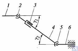
Figure 1. Diagram of a universal joint drive: 1, 4, 6 — driveshafts; 2, 5 — universal joints; 3 — compensating connection; u1, u2 — angles between shafts
Генерално, погон карданским зглобом састоји се од карданских зглобова 2 и 5, карданских вратила 1, 4 и 6 и компензационог споја 3. Понекад је карданско вратило постављено на међуносачу причвршћеном за попречни носач рама возила. Кардански зглобови обезбеђују пренос обртног момента између вратила чије се осе секу под углом. Кардански зглобови се деле на неуједначене и зглобове константне брзине. Зглобови неједнаке брзине се даље класификују на еластичне и круте типове. Зглобови константне брзине могу бити куглични са жлебовима за подељење, куглични са полугом за подељење и брегасти. Типично се уграђују у погон водећих контролисаних точкова, где угао између вратила може достићи 45°, а центар карданског зглоба мора се поклопити са тачком пресека оса ротације точка и његове осе окретања.
Еластични кардански зглобови преносе обртни момент између вратила са осама које се пресецају под углом од 2...3° услед еластичне деформације спојних елемената. Крути зглоб неравномерне брзине преноси обртни момент са једног вратила на друго кроз покретну везу крутих делова. Састоји се од два јарма – 3 и 5, у чије су цилиндричне рупе уметнути крајеви А, Б, В и Г спојног елемента – крста 4, на лежајевима. Јармови су круто повезани са вратилима 1 и 2. Јарам 5 може да се окреће око осе БГ крста и истовремено, заједно са крстом, да се окреће око осе АВ, чиме се омогућава пренос ротације са једног вратила на друго са променљивим углом између њих.
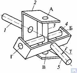
Figure 2. Diagram of a rigid non-uniform velocity universal joint
If shaft 7 rotates around its axis by an angle α, then shaft 2 will rotate by an angle β over the same period. The relationship between the rotation angles of shafts 7 and 2 is determined by the expression tanα = tanβ * cosγ, где је γ угао под којим су осе вратила позициониране. Овај израз показује да је угао β понекад мањи, једнак или већи од угла α. Једнакост ових углова се јавља на сваких 90° ротације вратила 7. Стога, при равномерној ротацији вратила 1, угаона брзина вратила 2 је неуједначена и мења се по синусоидном закону. Неједноликост ротације вратила 2 постаје значајнија како се повећава угао γ између оса вратила.
If the non-uniform rotation of shaft 2 is transmitted to the shafts of the units, additional pulsating loads will occur in the transmission, increasing with the angle γ. To prevent the non-uniform rotation of shaft 2 from being transmitted to the unit shafts, two universal joints are used in the universal joint drive. They are installed so that the angles γ1 and γ2 are equal; the forks of the universal joints, fixed on the non-uniformly rotating shaft 4, should be positioned in the same plane.
Дизајн главних делова карданских зглобова је приказан на слици 3. Кардански зглоб са неравномерном брзином састоји се од два јарма (1) повезана крстом (3). Један од јарма понекад има прирубницу, док је други заварен за цев карданског вратила или има ожљебљени крај (6) (или чауру) за повезивање са карданским вратилом. Зупци крста су уграђени у ушице оба јарма на игличастим лежајевима (7). Сваки лежај је смештен у кућиште (2) и држи се у ушици јарма помоћу поклопца, који је причвршћен за јарам са два вијка закључана језичцима на подлошци. У неким случајевима, лежајеви су причвршћени у јармама помоћу осигурача. Да би се задржало подмазивање у лежају и заштитило га од воде и прљавштине, постоји гумена самозатезна заптивка. Унутрашња шупљина крста је испуњена машћу кроз мазаљку, која допире до лежајева. Крст обично има сигурносни вентил који штити заптивку од оштећења услед притиска масти која се пумпа у крст. Зубчасти спој (6) се подмазује помоћу мазалице (5).
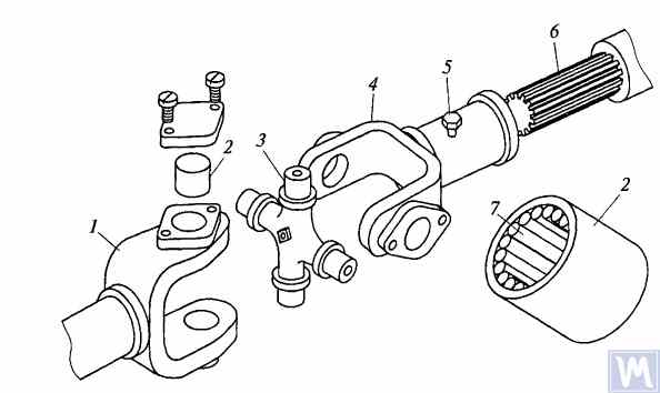
Figure 3. Details of a rigid non-uniform velocity universal joint
Максимални угао између оса вратила спојених крутим неуједначеним брзинским карданским зглобовима обично не прелази 20°, јер се ефикасност значајно смањује при већим угловима. Ако се угао између оса вратила мења у опсегу од 0...2%, осовине крста се деформишу игличастим лежајевима, што доводи до брзог отказа карданског зглоба.
У преносницима брзих гусеничних возила често се користе кардански зглобови са типовима зупчастих спојница, који омогућавају пренос обртног момента између вратила са осама које се секу под угловима до 1,5...2°.
Driveshafts are typically made tubular, using special steel seamless or welded tubes. The yokes of the universal joints, splined sleeves, or tips are welded to the tubes. To reduce the transverse loads acting on the driveshaft, dynamic balancing is performed with the universal joints assembled. Imbalance is corrected by welding balancing plates to the driveshaft or sometimes by installing balancing plates under the bearing caps of the universal joints. The relative position of the splined connection parts after assembly and balancing of the universal joint drive at the factory is usually marked with special labels.
The compensating connection of the universal joint drive is usually made in the form of a splined connection, allowing axial movement of the universal joint drive parts. It consists of a splined tip that fits into the splined sleeve of the universal joint drive. Lubrication is introduced into the splined connection through a grease fitting or applied during assembly and replaced after prolonged use of the vehicle. A seal and a cover are typically installed to prevent grease leakage and contamination.
For long driveshafts, intermediate supports are usually used in universal joint drives. An intermediate support typically consists of a bracket bolted to the vehicle frame cross member, in which a ball bearing is mounted in a rubber elastic ring. The bearing is sealed on both sides with caps and has a lubrication device. The elastic rubber ring helps to compensate for assembly inaccuracies and bearing misalignment that may occur due to frame deformations.
A universal joint with needle bearings (Figure 4a) consists of yokes, a cross, needle bearings, and seals. The cups with needle bearings are fitted onto the trunnions of the cross and sealed with seals. The cups are secured in the yokes with snap rings or caps fastened with screws. Universal joints are lubricated through a grease fitting via internal drillings in the cross. A safety valve is used to eliminate excess oil pressure in the joint. During uniform rotation of the driving yoke, the driven yoke rotates non-uniformly: it advances and lags behind the driving yoke twice per revolution. To eliminate non-uniform rotation and reduce inertial loads, two universal joints are used.
In the drive to the front driving wheels, constant velocity universal joints are installed. The constant velocity joint drive of GAZ-66 and ZIL-131 vehicles consists of yokes 2, 5 (Figure 4b), four balls 7, and a central ball 8. The driving yoke 2 is integral with the inner axle shaft, while the driven yoke is forged together with the outer axle shaft, at the end of which the wheel hub is fixed. The driving moment from yoke 2 to yoke 5 is transmitted through balls 7, which move along circular grooves in the yokes. The central ball 8 serves to center the yokes and is held in place by studs 3, 4. The rotation frequency of yokes 2, 5 is the same due to the symmetry of the mechanism relative to the yokes. The change in shaft length is ensured by the free splined connections of the yokes with the shaft.
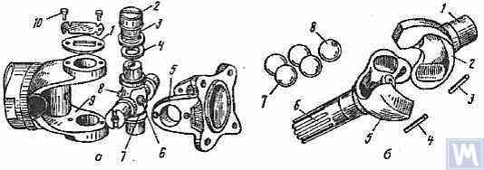
Figure 4. Universal Joints: a — universal joint: 1 — cap; 2 — cup; 3 — needle bearing; 4 — seal; 5, 9 — yokes; 6 — safety valve; 7 — cross; 8 — grease fitting; 10 — screw; b — constant velocity universal joint: 1 — inner axle shaft; 2 — driving yoke; 3, 4 — studs; 5 — driven yoke; 6 — outer axle shaft; 7 — balls; 8 — central ball
2. Universal Joint Drive Malfunctions
Universal joint drive malfunctions typically manifest as sharp knocks in the universal joints that occur when the vehicle is moving, especially during shifts between gears and sudden increases in the engine crankshaft speed (for example, when transitioning from engine braking to acceleration). A sign of universal joint malfunction can be its heating to a high temperature (over 100°C). This happens due to significant wear of the bushings and trunnions of the universal joint, needle bearings, crosses, and splined connections, resulting in misalignment of the universal joint and significant impact axial loads on the needle bearings. Damage to the cork seals of the universal joint cross leads to rapid wear of the trunnion and its bearing.
During maintenance, the universal joint drive is checked by sharply rotating the driveshaft by hand in both directions. The degree of free rotation of the shaft determines the wear of the universal joints and splined connections. Every 8-10 thousand kilometers, the condition of the bolted connections of the driven shaft flanges of the gearbox and the drive shaft of the main transmission gear with the flanges of the end universal joints and the fastening of the intermediate support of the driveshaft are checked. The condition of the rubber boots on the splined connections and the cork seals of the universal joint cross is also checked. All fastening bolts must be tightened fully (tightening torque 8-10 kgf·m).
Needle bearings of the universal joints are lubricated with liquid oil used for transmission units; splined connections in most vehicles are lubricated with greases (US-1, US-2, 1-13, etc.); the use of grease for lubricating needle bearings is strictly prohibited. In some vehicles, splined connections are lubricated with transmission oil. The intermediate support bearing, mounted in a rubber sleeve, practically does not require lubrication, as it is lubricated during assembly at the factory. The support bearing of the ZIL-130 vehicle is lubricated with grease through a pressure fitting during regular maintenance (every 1100-1700 km).
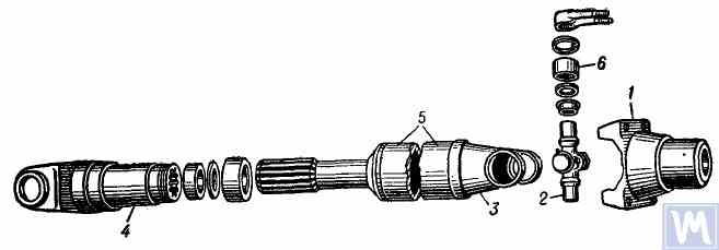
Figure 5. Universal joint drive: 1 — flange for securing the driveshaft; 2 — universal joint cross; 3 — universal joint yoke; 4 — sliding yoke; 5 — driveshaft tube; 6 — needle roller bearing with closed end
The universal joint drive consists of two universal joints with needle bearings, connected by a hollow shaft, and a sliding yoke with involute splines. To ensure reliable protection from dirt and provide good lubrication of the splined connection, the sliding yoke (6), connected to the secondary shaft (2) of the gearbox, is placed in an extension (1) attached to the gearbox housing. Additionally, this location of the splined connection (outside the zone between the joints) significantly increases the stiffness of the universal joint drive and reduces the likelihood of shaft vibrations when the sliding splined connection wears out.
Погонско вратило је направљено од танкозидне електрично заварене цеви (8), у коју су два идентична јарма (9) утиснута на сваком крају, а затим заварена електролучним заваривањем. Кућишта игличастих лежајева (18) крста (25) су утиснута у уши јарма (9) и осигурана су опружним прстеновима (20). Сваки лежај карданског зглоба садржи 22 игле (21). Утиснуте капице (24) су утиснуте на избочене зупце крста, у које су уграђени прстенови од плуте (23). Лежајеви се подмазују помоћу угаоне мазнице (17) уврнуте у навојни отвор у центру крста, повезан са пролазним каналима у зупцима крста. На супротној страни крста карданског зглоба, у његовом центру се налази сигурносни вентил (16), дизајниран да испусти вишак масти приликом пуњења крста и лежајева и да спречи нагомилавање притиска унутар крста током рада (вентил се активира при притиску од око 3,5 кг/цм²). Неопходност уградње сигурносног вентила је због чињенице да прекомерно повећање притиска унутар крста може довести до оштећења (екструзије) плутаних заптивача.
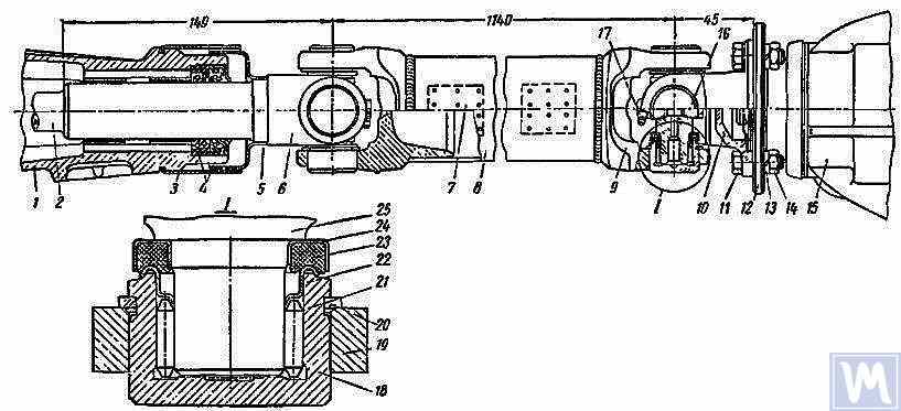
Figure 6. Driveshaft Assembly: 1 — gearbox extension; 2 — secondary shaft of the gearbox; 3 and 5 — dirt deflectors; 4 — rubber seals; 6 — sliding yoke; 7 — balancing plate; 8 — driveshaft tube; 9 — yoke; 10 — flange yoke; 11 — bolt; 12 — flange of the rear axle drive gear; 13 — spring washer; 14 — nut; 15 — rear axle; 16 — safety valve; 17 — angular grease fitting; 18 — needle bearing; 19 — yoke eye; 20 — spring retaining ring; 21 — needle; 22 — washer with toroidal end; 23 — cork ring; 24 — stamped cap; 25 — cross
Карданско вратило, састављено са оба карданска зглоба, пажљиво је динамички балансирано на оба краја заваривањем балансирајућих плоча (7) на цев. Стога, приликом демонтаже вратила, сви његови делови морају бити пажљиво означени како би се могли поново саставити у своје првобитне положаје. Непоштовање овог упутства нарушава равнотежу вратила, узрокујући вибрације које могу оштетити мењач и каросерију возила. Ако се појединачни делови истроше, посебно ако се цев савије услед удара и постане немогуће динамички балансирати вратило након монтаже, цело вратило мора бити замењено.
Possible Driveshaft Malfunctions, Their Causes, and Solutions
| Cause of Malfunction | Solution |
|---|---|
| Driveshaft Vibration | |
| 1. Shaft bending due to an obstacle | 1. Straighten and dynamically balance the assembled shaft or replace the assembled shaft |
| 2. Bearing and cross wear | 2. Replace bearings and crosses and dynamically balance the assembled shaft |
| 3. Wear of extension bushings and sliding yoke | 3. Replace the extension and sliding yoke and dynamically balance the assembled shaft |
| Knocks When Starting and Coasting | |
| 1. Wear of sliding yoke splines or secondary gearbox shaft | 1. Replace worn parts. When replacing the sliding yoke, dynamically balance the assembled shaft |
| 2. Loose bolts securing the flange yoke to the rear axle drive gear flange | 2. Tighten bolts |
| Oil Throwing from Universal Joint Seals | |
| Wear of cork rings in universal joint seals | Replace cork rings, maintaining the relative position of all driveshaft parts during reassembly. If there is wear on crosses and bearings, replace the bearings and crosses and dynamically balance the assembled shaft |
3. Driveshaft Balancing
After repairing and assembling the driveshaft, it is dynamically balanced on a machine. One design of a balancing machine is shown in Figure 7. The machine consists of a plate (18), a pendulum frame (8) mounted on four vertical elastic rods (3), ensuring its oscillation in the horizontal plane. A bracket and front headstock (9), secured on a bracket (4), are mounted on the longitudinal tubes of the pendulum frame (8). The rear headstock (6) is on a movable traverse (5), allowing dynamic balancing of driveshafts of different lengths. The headstock spindles are mounted on precision ball bearings. The spindle of the front headstock (9) is driven by an electric motor installed in the machine base, through a V-belt drive and an intermediate shaft, on which a limb (10) (graduated disk) is mounted. Additionally, two stands (15) with retractable locking pins (17) are installed on the machine plate (18), ensuring the fixation of the front and rear ends of the pendulum frame depending on the balancing of the front or rear end of the driveshaft.
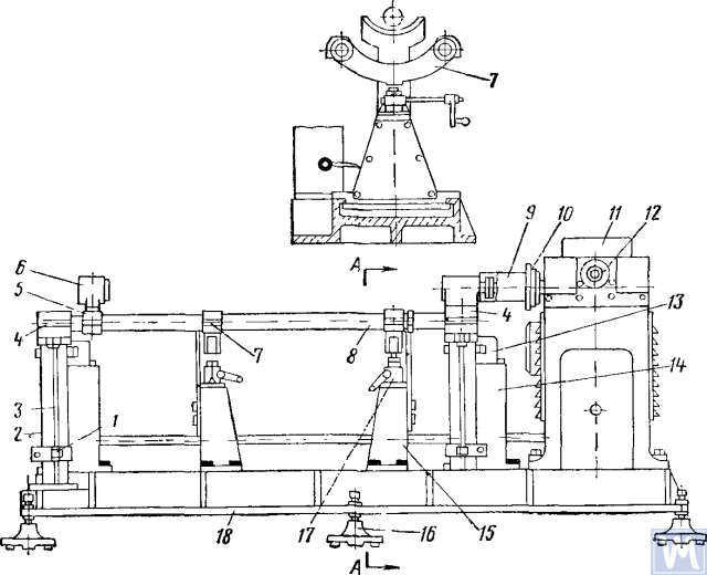
Figure 7. Dynamic Balancing Machine for Driveshafts
1—clamp; 2—dampers; 3—elastic rod; 4—bracket; 5—movable traverse; 6—rear headstock; 7—crossbar; 8—pendulum frame; 9—front driving headstock; 10—limb-disk; 11—millivoltmeter; 12—limb of the commutator-rectifier shaft; 13—magnetoelectric sensor; 14—fixed stand; 15—fixator stand; 16—support; 17—fixator; 18—support plate
The fixed stands (14) are mounted at the rear of the machine plate, and magnetoelectric sensors (13) are installed on them, with rods connected to the ends of the pendulum frame. To prevent resonance vibrations of the frame, dampers (2) filled with oil are installed under the brackets (4).
Током динамичког балансирања, склоп карданског вратила са клизним јармом се поставља и причвршћује на машину. Један крај карданског вратила је повезан прирубницом-јармом са прирубницом предњег погонског вретена, а други крај носећим вратом клизног јарма са ожљебном чауром задњег вретена. Затим се проверава лакоћа окретања карданског вратила, а један крај рама клатна машине се фиксира помоћу фиксатора. Након покретања машине, крак исправљача се окреће у смеру супротном од казаљке на сату, доводећи иглу миливолтметра до максималног очитавања. Очитавање миливолтметра одговара величини неравнотеже. Скала миливолтметра је градуисана у грам-центиметрима или грамима противтега. Наставком окретања крака исправљача у смеру супротном од казаљке на сату, очитавање миливолтметра се доводи до нуле и машина се зауставља. На основу очитавања крака исправљача одређује се угаоно померање (угао померања неравнотеже), а ручним окретањем карданског вратила ова вредност се подешава на средњем краку вратила. Место заваривања балансирајуће плоче биће на врху карданског вратила, а оптерећени део на дну у равни корекције. Затим се балансирајућа плоча причвршћује и везује танком жицом на растојању од 10 mm од завара, машина се покреће и проверава се равнотежа краја карданског вратила са плочом. Неравнотежа не сме бити већа од 70 g cm. Затим, ослобађањем једног краја и осигуравањем другог краја рама клатна помоћу постоља за фиксирање, врши се динамичко балансирање другог краја карданског вратила према горе описаном технолошком редоследу.
Driveshafts have some balancing features. For most parts, the base for dynamic balancing is the support necks (e.g., rotors of electric motors, turbines, spindles, crankshafts, etc.), but for driveshafts, it is the flanges. During assembly, there are unavoidable gaps in different connections leading to imbalance. If the minimum imbalance cannot be achieved during balancing, the shaft is rejected. The accuracy of balancing is influenced by the following factors:
- Gap in the connection between the landing belt of the driveshaft flange and the inner hole of the clamping flange of the left and right support headstocks;
- Radial and end runout of the base surfaces of the flange;
- Зазори у шарнирним и жлебним спојевима. Присуство масти у шупљини жлебног споја може довести до „плутајуће“ неравнотеже. Ако то спречава постизање потребне тачности балансирања, карданско вратило се балансира без масти.
Some imbalances may be completely uncorrectable. If increased friction is observed in the universal joints of the driveshaft, the mutual influence of the correction planes increases. This leads to a decrease in the performance and accuracy of balancing.
Према OST 37.001.053-74, утврђени су следећи стандарди неравнотеже: карданска вратила са два зглоба (двоносна) се динамички балансирају, а са три (троносна) – склопљена са средњим носачем; прирубнице (јармови) карданских вратила и спојница тежине веће од 5 кг се статички балансирају пре склапања вратила или спојнице; норме преостале неравнотеже за карданска вратила на сваком крају или на средњем носачу трозглобних карданских вратила процењују се специфичном неравнотежом;
Максимално дозвољена специфична норма преосталог дисбаланса на сваком крају вратила или на међуносачу, као и за трозглобна карданска вратила у било ком положају на балансирајућем постољу, не сме прећи: за мењаче путничких аутомобила и камиона малог терета (до 1 т) и веома малих аутобуса – 6 г-цм/кг, за остале – 10 г-цм/кг. Максимално дозвољена норма преосталог дисбаланса карданског вратила или трозглобног карданског вратила треба да буде обезбеђена на балансирајућем постољу на фреквенцији обртања која одговара њиховим фреквенцијама у мењачу при максималној брзини возила.
За карданска вратила и трозглобна карданска вратила камиона носивости 4 т и више, малих и великих аутобуса, дозвољено је смањење фреквенције обртања на балансирајућем постољу на 70% фреквенције обртања трансмисионих вратила при максималној брзини возила. Према OST 37.001.053-74, фреквенција обртања балансираних карданских вратила треба да буде једнака:
нb = (0,7 ... 1,0) nr,
where nb – фреквенција ротације балансирања (треба да одговара главним техничким подацима постоља, n=3000 min-1; nr – максимална радна фреквенција ротације, мин-1.
In practice, due to the gap in the joints and splined connections, the driveshaft cannot be balanced at the recommended rotation frequency. In this case, another rotation frequency is chosen, at which it balances.
4. Modern Balancing Machines for Driveshafts
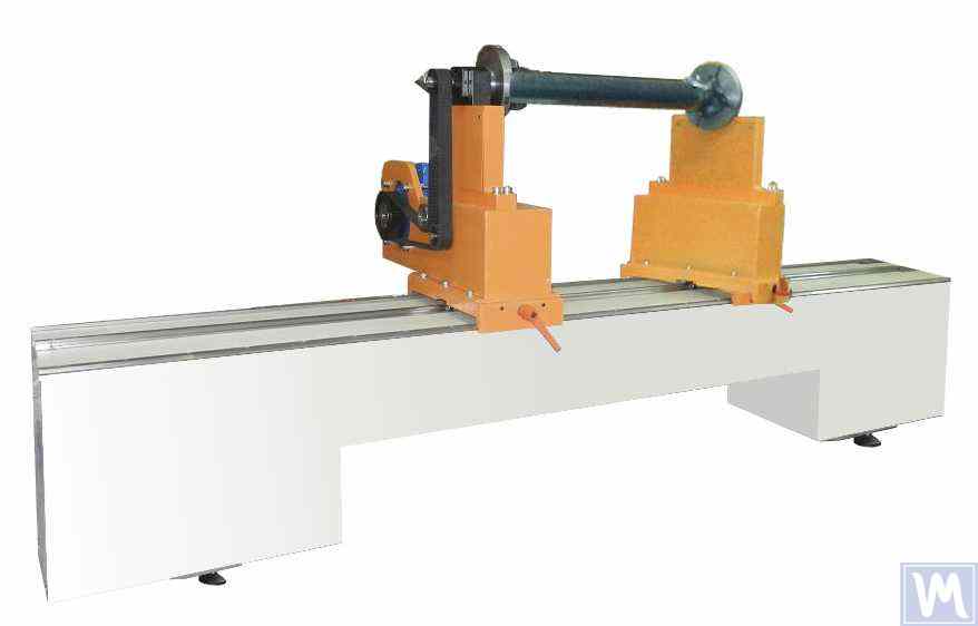
Figure 8. Balancing Machine for Driveshafts up to 2 Meters Long, Weighing up to 500 kg
The model has 2 stands and allows balancing in 2 correction planes.
Balancing Machine for Driveshafts up to 4200 mm Long, Weighing up to 400 kg
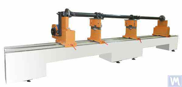
Figure 9. Balancing Machine for Driveshafts up to 4200 mm Long, Weighing up to 400 kg
The model has 4 stands and allows balancing in 4 correction planes simultaneously.
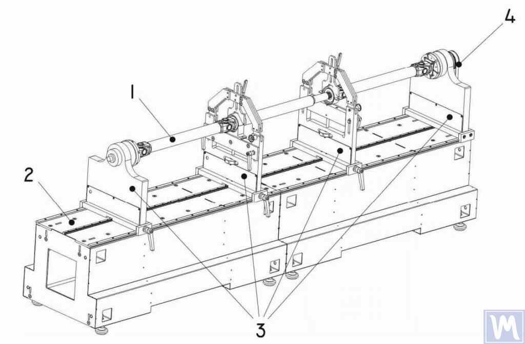
Figure 10. Horizontal Hard Bearing Balancing Machine for Dynamic Balancing of Driveshafts
1 – Balancing item (driveshaft); 2 – Machine base; 3 – Machine supports; 4 – Machine drive; The structural elements of the machine supports are shown in Figure 9.
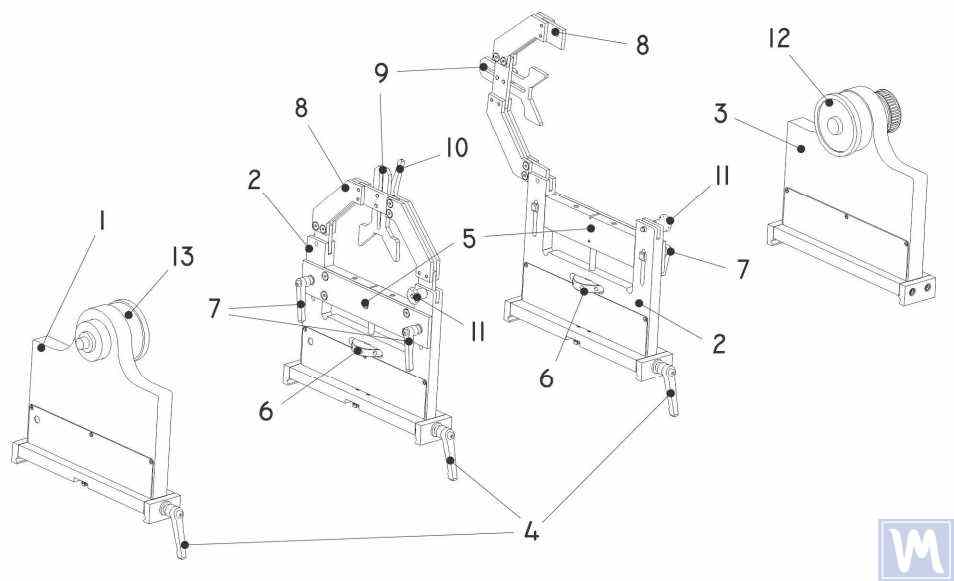
Figure 11. Machine Support Elements for Dynamic Balancing of Driveshafts
1 – Left non-adjustable support; 2 – Intermediate adjustable support (2 pcs.); 3 – Right non-adjustable fixed support; 4 – Support frame lock handle; 5 – Movable support platform; 6 – Support vertical adjustment nut; 7 – Vertical position lock handles; 8 – Support clamping bracket; 9 – Intermediate bearing movable clamp; 10 – Clamp lock handle; 11 – Clamping bracket lock; 12 – Drive (leading) spindle for item installation; 13 – Driven spindle
5. Preparation for Driveshaft Balancing
Below, we will consider the setup of the machine supports and the installation of the balancing item (four-support driveshaft) on the machine supports.
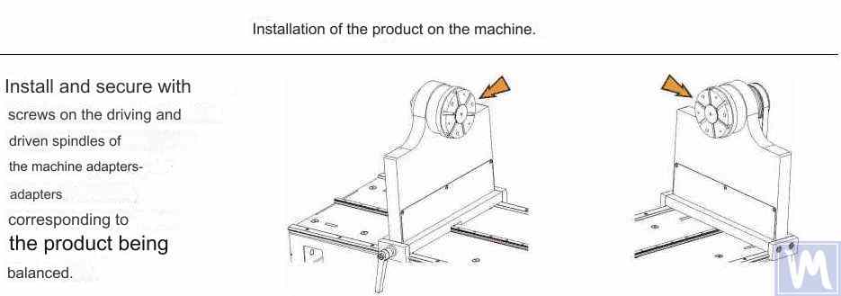
Figure 12. Installation of Transitional Flanges on the Spindles of the Balancing Machine

Figure 13. Installation of the Driveshaft on the Supports of the Balancing Machine

Figure 14. Leveling the Driveshaft Horizontally on the Supports of the Balancing Machine Using a Bubble Level
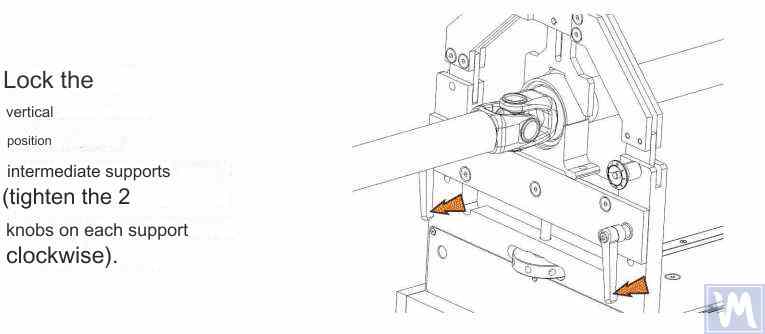
Figure 15. Fixing the Intermediate Supports of the Balancing Machine to Prevent Vertical Displacement of the Driveshaft
Rotate the item manually for a full turn. Ensure that it rotates freely and without jamming on the supports. After this, the mechanical part of the machine is set up, and the item installation is complete.
6. Driveshaft Balancing Procedure
The process of driveshaft balancing on the balancing machine will be considered using the Balanset-4 measuring system as an example. The Balanset-4 is a portable balancing kit designed for balancing in one, two, three, and four correction planes of rotors, either rotating in their own bearings or mounted on a balancing machine. The device includes up to four vibration sensors, a phase angle sensor, a four-channel measuring unit, and a portable computer.
The entire balancing process, including measurement, processing, and display of information on the magnitude and location of corrective weights, is performed automatically and does not require the user to have additional skills and knowledge beyond the provided instructions. The results of all balancing operations are saved in the Balancing Archive and can be printed as reports if necessary. In addition to balancing, the Balanset-4 can also be used as a regular vibro-tachometer, allowing measurement on four channels of the root mean square (RMS) value of total vibration, RMS of the rotational component of vibration, and control of rotor rotation frequency.
Furthermore, the device allows displaying graphs of the time function and vibration spectrum by vibration velocity, which can be useful in assessing the technical condition of the balanced machine.
Figure 16. External View of the Balanset-4 Device for Use as a Measuring and Computing System of the Driveshaft Balancing Machine
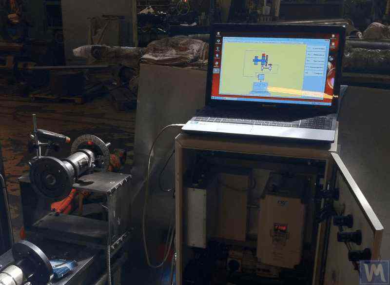
Figure 17. Example of Using the Balanset-4 Device as a Measuring and Computing System of the Driveshaft Balancing Machine
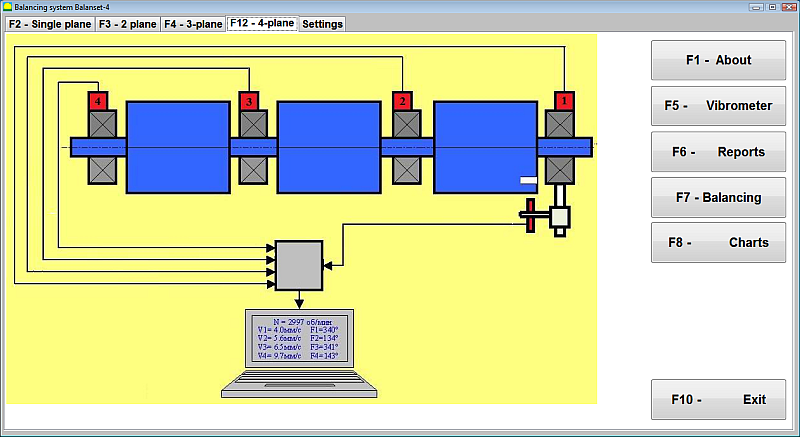
Figure 18. User Interface of the Balanset-4 Device
Уређај Balanset-4 може бити опремљен са две врсте сензора – вибрационим акцелерометрима за мерење вибрација (убрзања вибрација) и сензорима силе. Сензори вибрација се користе за рад на машинама за балансирање типа после резонанце, док се сензори силе користе за машине типа пре резонанце.

Figure 19. Installation of Balanset-4 Vibration Sensors on the Supports of the Balancing Machine
Правац осе осетљивости сензора треба да се поклапа са правцем померања вибрација носача, у овом случају – хоризонтално. За додатне информације о уградњи сензора, погледајте БАЛАНСИРАЊЕ РОТОРА У РАДНИМ УСЛОВИМА. Уградња сензора силе зависи од конструктивних карактеристика машине.
- Install vibration sensors 1, 2, 3, 4 on the supports of the balancing machine.
- Connect the vibration sensors to connectors X1, X2, X3, X4.
- Install the phase angle sensor (laser tachometer) 5 so that the nominal gap between the radial (or end) surface of the balanced rotor and the sensor housing is in the range of 10 to 300 mm.
- Attach a reflective tape mark with a width of at least 10-15 mm to the rotor surface.
- Connect the phase angle sensor to connector X5.
- Connect the measuring unit to the computer’s USB port.
- When using mains power, connect the computer to the power supply unit.
- Connect the power supply unit to a 220 V, 50 Hz network.
- Turn on the computer and select the “BalCom-4” program.
- Press the “F12-four-plane” button (or the F12 function key on the computer keyboard) to select the mode for measuring vibration simultaneously in four planes using vibration sensors 1, 2, 3, 4, connected respectively to inputs X1, X2, X3, and X4 of the measuring unit.
- A mnemonic diagram illustrating the process of measuring vibration simultaneously on four measurement channels (or the process of balancing in four planes) appears on the computer display, as shown in Figure 16.
Before performing balancing, it is recommended to take measurements in the vibrometer mode (F5 button).
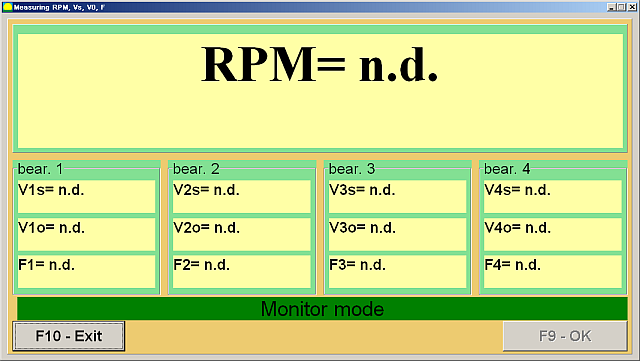
Figure 20. Vibrometer Mode Measurements
Ако укупна магнитуда вибрација V1s (V2s) приближно одговара магнитуди ротационе компоненте V1o (V2o), може се претпоставити да је главни допринос вибрацијама механизма последица неравнотеже ротора. Ако укупна магнитуда вибрација V1s (V2s) значајно премашује ротациону компоненту V1o (V2o), препоручује се преглед механизма – провера стања лежајева, осигурање сигурног монтирања на темељ, провера да ли ротор не додирује непокретне делове током ротације и разматрање утицаја вибрација других механизама итд.
Проучавање графикона временске функције и спектара вибрација добијених у режиму „Графикони-Спектрална анализа“ може бити корисно овде.
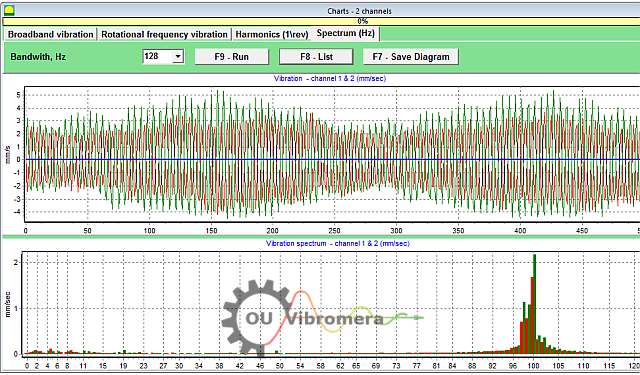
Figure 21. Vibration Time Function and Spectrum Graphs
График приказује на којим фреквенцијама су нивои вибрација највиши. Ако се ове фреквенције разликују од фреквенције обртања ротора уравнотеженог механизма, потребно је идентификовати изворе ових компоненти вибрација и предузети мере за њихово елиминисање пре балансирања.
It is also important to pay attention to the stability of the readings in vibrometer mode – the amplitude and phase of the vibration should not change by more than 10-15% during measurement. Otherwise, the mechanism might be operating near a resonance region. In this case, the rotor speed should be adjusted.
Приликом извођења балансирања у четири равни у режиму „Примарно“, потребно је пет калибрационих вожњи и најмање једна верификациона вожња балансиране машине. Мерење вибрација током прве вожње машине без пробног тега врши се у радном простору „Балансирање у четири равни“. Накнадне вожње се изводе са пробним тегом, секвенцијално инсталираним на погонској осовини у свакој корекционој равни (у подручју сваког носача балансирајуће машине).
Before each subsequent run, the following steps should be taken:
- Зауставите ротацију ротора уравнотежене машине.
- Remove the previously installed trial weight.
- Install the trial weight in the next plane.
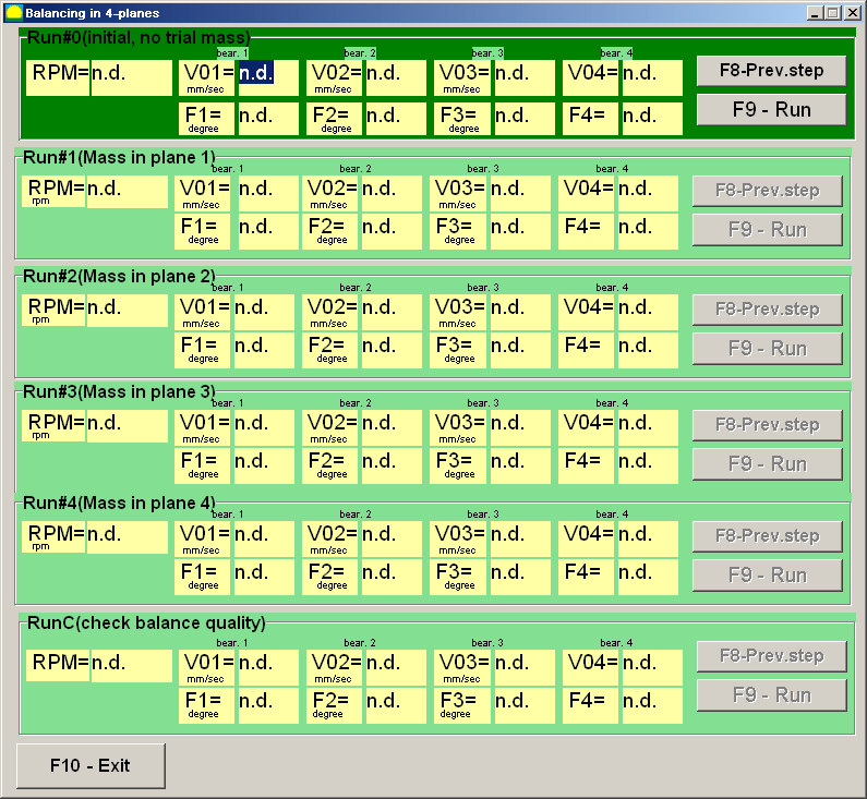
Figure 23. Four-Plane Balancing Workspace
Након завршетка сваког мерења, резултати фреквенције ротације ротора (Nob), as well as the RMS values (Vo1, Вo2, Вo3, Вo4) and the phases (F1, F2, F3, F4) вибрација на фреквенцији обртања уравнотеженог ротора чувају се у одговарајућим пољима у прозору програма. Након петог покретања (Тег у равни 4), појављује се радни простор „Балансирајући тегови“ (видети слику 24), приказујући израчунате вредности маса (M1, M2, M3, M4) and the installation angles (f1, f2, f3, f4) of the corrective weights that need to be installed on the rotor in four planes to compensate for its imbalance.
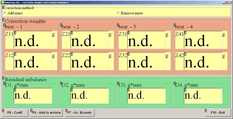
Figure 24. Workspace with Calculated Parameters of Corrective Weights in Four Planes
Attention! Након завршетка процеса мерења током петог покретања балансиране машине, потребно је зауставити ротацију ротора и уклонити претходно постављени пробни тег. Тек након тога можете наставити са постављањем (или уклањањем) корективних тегова на ротору.
Угаони положај за додавање (или уклањање) корективног тега на ротору у поларном координатном систему мери се од места постављања пробног тега. Правац мерења угла поклапа се са смером ротације ротора. У случају балансирања лопатицама, лопатица уравнотеженог ротора, условно сматрана првом лопатицом, поклапа се са местом постављања пробног тега. Правац нумерације лопатица приказан на екрану рачунара прати смер ротације ротора.
У овој верзији програма, подразумевано се претпоставља да ће корективни тег бити додат ротору. То је назначено ознаком постављеном у пољу „Додај“. Ако је потребно исправљање неравнотеже уклањањем тега (нпр. бушењем), поставите ознаку у поље „Уклони“ помоћу миша, након чега ће се угаони положај корективног тега аутоматски променити за 180 степени.
Након постављања корективних тегова на балансирани ротор, притисните дугме „Излаз – F10“ (или функцијски тастер F10 на тастатури рачунара) да бисте се вратили на претходни радни простор „Балансирање у четири равни“ и проверили ефикасност операције балансирања. Након завршетка верификационог рада, резултати фреквенције ротације ротора (Nob) and the RMS values (Vo1, Вo2, Вo3, Вo4) and phases (F1, F2, F3, F4) вибрација на фреквенцији обртања уравнотеженог ротора се чувају. Истовремено, радни простор „Балансирање тегова“ (видети слику 21) се појављује преко радног простора „Балансирање у четири равни“, приказујући израчунате параметре додатних корективних тегова које је потребно инсталирати (или уклонити) на ротор да би се компензовала његова резидуална неравнотежа. Поред тога, овај радни простор приказује вредности резидуалне неравнотеже постигнуте након балансирања. Ако вредности резидуалне вибрације и/или резидуалне неравнотеже уравнотеженог ротора испуњавају захтеве толеранције наведене у техничкој документацији, процес балансирања се може завршити. У супротном, процес балансирања се може наставити. Ова метода омогућава исправљање могућих грешака кроз узастопне апроксимације које се могу јавити приликом инсталирања (уклањања) корективног тега на уравнотеженом ротору.
Ако се процес балансирања настави, додатни корективни тегови морају бити инсталирани (или уклоњени) на балансираном ротору према параметрима наведеним у радном простору „Балансирајући тегови“.
Дугме „Коефицијенти – F8“ (или функционални тастер F8 на тастатури рачунара) користи се за преглед и чување у меморији рачунара коефицијената балансирања ротора (коефицијената динамичког утицаја) израчунатих из резултата пет калибрационих вожњи.
7. Recommended Balancing Accuracy Classes for Rigid Rotors
Table 2. Recommended Balancing Accuracy Classes for Rigid Rotors.

Recommended Balancing Accuracy Classes for Rigid Rotors
| Types of Machines (Rotors) | Balancing Accuracy Class | Value eper Ω mm/s |
|---|---|---|
| Drive crankshafts (structurally unbalanced) for large low-speed marine diesel engines (piston speed less than 9 m/s) | G 4000 | 4000 |
| Drive crankshafts (structurally balanced) for large low-speed marine diesel engines (piston speed less than 9 m/s) | G 1600 | 1600 |
| Drive crankshafts (structurally unbalanced) on vibration isolators | G 630 | 630 |
| Drive crankshafts (structurally unbalanced) on rigid supports | G 250 | 250 |
| Reciprocating engines assembled for passenger cars, trucks, and locomotives | G 100 | 100 |
| Automobile parts: wheels, wheel rims, wheelsets, transmissions | ||
| Drive crankshafts (structurally balanced) on vibration isolators | G 40 | 40 |
| Agricultural machines | G 16 | 16 |
| Drive crankshafts (balanced) on rigid supports | ||
| Crushers | ||
| Drive shafts (driveshafts, screw shafts) | ||
| Aircraft gas turbines | G 6.3 | 6.3 |
| Centrifuges (separators, settlers) | ||
| Electric motors and generators (with a shaft height of at least 80 mm) with a maximum nominal rotation speed of up to 950 min-1 | ||
| Electric motors with a shaft height of less than 80 mm | ||
| Fans | ||
| Gear drives | ||
| General-purpose machines | ||
| Metal cutting machines | ||
| Papermaking machines | ||
| Pumps | ||
| Turbochargers | ||
| Water turbines | ||
| Compressors | ||
| Computer-controlled drives | G 2.5 | 2.5 |
| Electric motors and generators (with a shaft height of at least 80 mm) with a maximum nominal rotation speed over 950 min-1 | ||
| Gas and steam turbines | ||
| Metal cutting machine drives | ||
| Textile machines | ||
| Audio and video equipment drives | G 1 | 1 |
| Grinding machine drives | ||
| Spindles and drives of high-precision equipment | G 0.4 | 0.4 |
Често постављана питања о балансирању карданског вратила
Шта је балансирање карданског вратила?
Балансирање карданског вратила је процес исправљања било какве неравнотеже масе у карданском вратилу тако да се оно глатко окреће без изазивања вибрација. Ово подразумева мерење где је вратило теже на једној страни, а затим додавање или уклањање малих количина тежине (на пример, заваривање балансирајућих тегова) како би се супротставило тој неравнотежи. Балансирано карданско вратило ради равномерно, што спречава прекомерне вибрације и хабање компоненти возила.
Зашто је балансирање карданског вратила важно?
Небалансирано карданско вратило може довести до јаких вибрација, посебно при одређеним брзинама, и може изазвати лупање током убрзања или промене брзина. Временом, ове вибрације могу оштетити лежајеве, карданске зглобове и друге компоненте погонског склопа. Балансирање карданског вратила елиминише ове вибрације, обезбеђујући глађу вожњу, смањујући оптерећење делова и спречавајући скупа оштећења или застоје.
Који су уобичајени симптоми неуравнотеженог погонског вратила?
Типични симптоми небалансираног или неисправног карданског вратила укључују приметне вибрације или подрхтавање које се осећа у поду возила или седишту, посебно како се брзина повећава. Такође можете чути куцање или звецкање приликом мењања брзина или током убрзања и успоравања. У неким случајевима, кардански зглоб се може прегрејати због неравнотеже. Ако приметите ове знаке, вероватно је потребно балансирање или поправку карданског вратила.
Како балансирате карданско вратило?
Балансирање карданског вратила се обично врши помоћу специјализоване машине за балансирање. Карданско вратило се монтира и окреће великом брзином док сензори детектују било какву неравнотежу. Техничар затим причвршћује мале тегове на карданско вратило (или уклања материјал) на одређеним позицијама на основу очитавања машине. Овај процес се понавља док се карданско вратило не окреће без значајних вибрација. Модерни системи попут Balanset-4 могу водити овај процес и тачно израчунати где и колико тегова треба додати за прецизно балансирање.
Conclusion
Закључно, правилно балансирање карданског вратила је неопходно за безбедност, перформансе и уштеду трошкова. Детекцијом и исправљањем неравнотеже спречавате непотребно хабање делова, избегавате штетне кварове и одржавате оптималне перформансе машине. Модерни системи за балансирање, попут наших уређаја Balanset-1 и Balanset-4, чине процес ефикасним, помажући чак и малим радионицама да постигну професионалне резултате.
Ако се суочавате са сталним вибрацијама карданског вратила или вам је потребно поуздано решење за балансирање, не оклевајте да делујете. Примените кораке наведене у овом водичу или се консултујте са нашим стручњацима за помоћ. Уз прави приступ и опрему, можете осигурати да ваше карданско вратило ради глатко и поуздано годинама које долазе. Контактирајте нас да бисте сазнали више или истражили најбољу опрему за балансирање карданског вратила за ваше потребе.


0 коментара