Drive Shaft Balancing: Comprehensive Guide
Devices for Dynamic Balancing of Driveshafts and Measurement System for Balancing Machines Balanset-4 – €6,803
Imagine you're driving a truck and suddenly feel a harsh vibration or hear a loud clunk when accelerating or changing gears. This is more than just a nuisance — it could be a sign of an unbalanced driveshaft. For engineers and technicians, such vibrations and noises indicate lost efficiency, accelerated wear on components, and potentially costly downtime if left unaddressed.
In this comprehensive guide, we provide practical solutions to driveshaft balance issues. You'll learn what a driveshaft is and why it needs balancing, recognize the common malfunctions that cause vibration or noise, and follow a clear step-by-step process for dynamic driveshaft balancing. By applying these best practices, you can save money on repairs, reduce troubleshooting time, and ensure your machinery or vehicle runs reliably with minimal vibration.
Table of Contents
- 1. Types of Driveshafts
- 2. Universal Joint Drive Malfunctions
- 3. Driveshaft Balancing
- 4. Modern Balancing Machines for Driveshafts
- 5. Preparation for Driveshaft Balancing
- 6. Driveshaft Balancing Procedure
- 7. Recommended Balancing Accuracy Classes for Rigid Rotors


1. Types of Driveshafts
A universal joint drive (driveshaft) is a mechanism that transmits torque between shafts that intersect at the center of the universal joint and can move relative to each other at an angle. In a vehicle, the driveshaft transmits torque from the gearbox (or transfer case) to the driven axles in the case of a classical or all-wheel-drive configuration. For all-wheel-drive vehicles, the universal joint usually connects the driven shaft of the gearbox to the drive shaft of the transfer case, and the driven shafts of the transfer case to the drive shafts of the main drives of the driven axles.
Units mounted on the frame (such as the gearbox and transfer case) can move relative to each other due to the deformation of their supports and the frame itself. Meanwhile, the drive axles are attached to the frame through the suspension and can move relative to the frame and the units mounted on it due to the deformation of the suspension's elastic elements. This movement can change not only the angles of the driveshafts connecting the units but also the distance between the units.
The universal joint drive has a significant disadvantage: the non-uniform rotation of the shafts. If one shaft rotates uniformly, the other does not, and this non-uniformity increases with the angle between the shafts. This limitation prevents the use of a universal joint drive in many applications, such as in the transmission of front-wheel-drive vehicles, where the main issue is transmitting torque to the turning wheels. This disadvantage can be partially compensated by using double universal joints on one shaft, which are turned a quarter of a turn relative to each other. However, in applications requiring uniform rotation, constant velocity joints (CV joints) are typically used instead. CV joints are a more advanced but also more complex design serving the same purpose.
Universal joint drives can consist of one or more universal joints connected by driveshafts and intermediate supports.
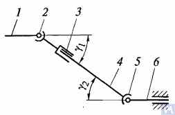
Figure 1. Diagram of a universal joint drive: 1, 4, 6 — driveshafts; 2, 5 — universal joints; 3 — compensating connection; u1, u2 — angles between shafts
In general, a universal joint drive consists of universal joints 2 and 5, driveshafts 1, 4, and 6, and a compensating connection 3. Sometimes the driveshaft is installed on an intermediate support attached to the vehicle frame cross member. Universal joints ensure the transmission of torque between shafts whose axes intersect at an angle. Universal joints are divided into non-uniform and constant velocity types. Non-uniform velocity joints are further classified into elastic and rigid types. Constant velocity joints can be ball-type with dividing grooves, ball-type with a dividing lever, and cam-type. They are typically installed in the drive of the leading controlled wheels, where the angle between the shafts can reach 45°, and the center of the universal joint must coincide with the intersection point of the wheel's rotation axes and its turning axis.
Elastic universal joints transmit torque between shafts with intersecting axes at an angle of 2...3° due to the elastic deformation of the connecting elements. A rigid non-uniform velocity joint transmits torque from one shaft to another through the movable connection of rigid parts. It consists of two yokes – 3 and 5, into the cylindrical holes of which the ends A, B, V, and G of the connecting element – the cross 4, are installed on bearings. The yokes are rigidly connected to shafts 1 and 2. Yoke 5 can rotate around axis BG of the cross and at the same time, along with the cross, rotate around axis AV, thereby enabling the transmission of rotation from one shaft to another with a changing angle between them.
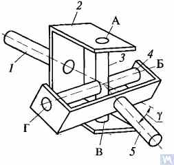
Figure 2. Diagram of a rigid non-uniform velocity universal joint
If shaft 7 rotates around its axis by an angle α, then shaft 2 will rotate by an angle β over the same period. The relationship between the rotation angles of shafts 7 and 2 is determined by the expression tanα = tanβ * cosγ, where γ is the angle at which the axes of the shafts are positioned. This expression indicates that the angle β is sometimes less than, equal to, or greater than angle α. Equality of these angles occurs every 90° of rotation of shaft 7. Therefore, with uniform rotation of shaft 1, the angular velocity of shaft 2 is non-uniform and varies according to a sinusoidal law. The non-uniformity of shaft 2's rotation becomes more significant as the angle γ between the shaft axes increases.
If the non-uniform rotation of shaft 2 is transmitted to the shafts of the units, additional pulsating loads will occur in the transmission, increasing with the angle γ. To prevent the non-uniform rotation of shaft 2 from being transmitted to the unit shafts, two universal joints are used in the universal joint drive. They are installed so that the angles γ1 and γ2 are equal; the forks of the universal joints, fixed on the non-uniformly rotating shaft 4, should be positioned in the same plane.
The design of the main parts of universal joint drives is shown in Figure 3. A non-uniform velocity universal joint consists of two yokes (1) connected by a cross (3). One of the yokes sometimes has a flange, while the other is welded to the driveshaft tube or has a splined end (6) (or sleeve) for connection to the driveshaft. The trunnions of the cross are installed in the eyes of both yokes on needle bearings (7). Each bearing is housed in a case (2) and held in the yoke's eye with a cap, which is attached to the yoke with two bolts locked by tabs on the washer. In some cases, the bearings are secured in the yokes with snap rings. To retain lubrication in the bearing and protect it from water and dirt, there is a rubber self-tightening seal. The inner cavity of the cross is filled with grease through a grease fitting, which reaches the bearings. The cross typically has a safety valve to protect the seal from damage due to the pressure of the grease being pumped into the cross. The splined connection (6) is lubricated using the grease fitting (5).
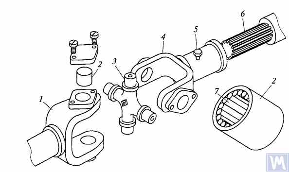
Figure 3. Details of a rigid non-uniform velocity universal joint
The maximum angle between the axes of shafts connected by rigid non-uniform velocity universal joints usually does not exceed 20°, as efficiency significantly decreases at larger angles. If the angle between the shaft axes varies within 0...2%, the trunnions of the cross are deformed by the needle bearings, causing the universal joint to fail quickly.
In the transmissions of high-speed tracked vehicles, universal joints with gear coupling types, which allow the transmission of torque between shafts with axes intersecting at angles up to 1.5...2°, are often used.
Driveshafts are typically made tubular, using special steel seamless or welded tubes. The yokes of the universal joints, splined sleeves, or tips are welded to the tubes. To reduce the transverse loads acting on the driveshaft, dynamic balancing is performed with the universal joints assembled. Imbalance is corrected by welding balancing plates to the driveshaft or sometimes by installing balancing plates under the bearing caps of the universal joints. The relative position of the splined connection parts after assembly and balancing of the universal joint drive at the factory is usually marked with special labels.
The compensating connection of the universal joint drive is usually made in the form of a splined connection, allowing axial movement of the universal joint drive parts. It consists of a splined tip that fits into the splined sleeve of the universal joint drive. Lubrication is introduced into the splined connection through a grease fitting or applied during assembly and replaced after prolonged use of the vehicle. A seal and a cover are typically installed to prevent grease leakage and contamination.
For long driveshafts, intermediate supports are usually used in universal joint drives. An intermediate support typically consists of a bracket bolted to the vehicle frame cross member, in which a ball bearing is mounted in a rubber elastic ring. The bearing is sealed on both sides with caps and has a lubrication device. The elastic rubber ring helps to compensate for assembly inaccuracies and bearing misalignment that may occur due to frame deformations.
A universal joint with needle bearings (Figure 4a) consists of yokes, a cross, needle bearings, and seals. The cups with needle bearings are fitted onto the trunnions of the cross and sealed with seals. The cups are secured in the yokes with snap rings or caps fastened with screws. Universal joints are lubricated through a grease fitting via internal drillings in the cross. A safety valve is used to eliminate excess oil pressure in the joint. During uniform rotation of the driving yoke, the driven yoke rotates non-uniformly: it advances and lags behind the driving yoke twice per revolution. To eliminate non-uniform rotation and reduce inertial loads, two universal joints are used.
In the drive to the front driving wheels, constant velocity universal joints are installed. The constant velocity joint drive of GAZ-66 and ZIL-131 vehicles consists of yokes 2, 5 (Figure 4b), four balls 7, and a central ball 8. The driving yoke 2 is integral with the inner axle shaft, while the driven yoke is forged together with the outer axle shaft, at the end of which the wheel hub is fixed. The driving moment from yoke 2 to yoke 5 is transmitted through balls 7, which move along circular grooves in the yokes. The central ball 8 serves to center the yokes and is held in place by studs 3, 4. The rotation frequency of yokes 2, 5 is the same due to the symmetry of the mechanism relative to the yokes. The change in shaft length is ensured by the free splined connections of the yokes with the shaft.
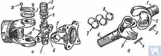
Figure 4. Universal Joints: a — universal joint: 1 — cap; 2 — cup; 3 — needle bearing; 4 — seal; 5, 9 — yokes; 6 — safety valve; 7 — cross; 8 — grease fitting; 10 — screw; b — constant velocity universal joint: 1 — inner axle shaft; 2 — driving yoke; 3, 4 — studs; 5 — driven yoke; 6 — outer axle shaft; 7 — balls; 8 — central ball
2. Universal Joint Drive Malfunctions
Universal joint drive malfunctions typically manifest as sharp knocks in the universal joints that occur when the vehicle is moving, especially during shifts between gears and sudden increases in the engine crankshaft speed (for example, when transitioning from engine braking to acceleration). A sign of universal joint malfunction can be its heating to a high temperature (over 100°C). This happens due to significant wear of the bushings and trunnions of the universal joint, needle bearings, crosses, and splined connections, resulting in misalignment of the universal joint and significant impact axial loads on the needle bearings. Damage to the cork seals of the universal joint cross leads to rapid wear of the trunnion and its bearing.
During maintenance, the universal joint drive is checked by sharply rotating the driveshaft by hand in both directions. The degree of free rotation of the shaft determines the wear of the universal joints and splined connections. Every 8-10 thousand kilometers, the condition of the bolted connections of the driven shaft flanges of the gearbox and the drive shaft of the main transmission gear with the flanges of the end universal joints and the fastening of the intermediate support of the driveshaft are checked. The condition of the rubber boots on the splined connections and the cork seals of the universal joint cross is also checked. All fastening bolts must be tightened fully (tightening torque 8-10 kgf·m).
Needle bearings of the universal joints are lubricated with liquid oil used for transmission units; splined connections in most vehicles are lubricated with greases (US-1, US-2, 1-13, etc.); the use of grease for lubricating needle bearings is strictly prohibited. In some vehicles, splined connections are lubricated with transmission oil. The intermediate support bearing, mounted in a rubber sleeve, practically does not require lubrication, as it is lubricated during assembly at the factory. The support bearing of the ZIL-130 vehicle is lubricated with grease through a pressure fitting during regular maintenance (every 1100-1700 km).
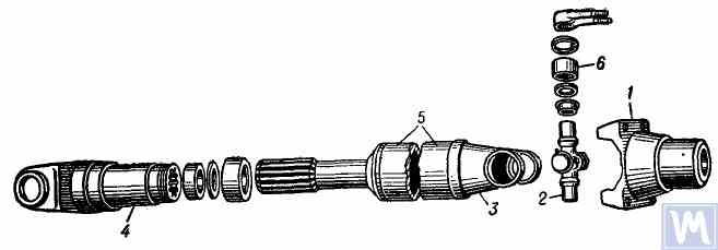
Figure 5. Universal joint drive: 1 — flange for securing the driveshaft; 2 — universal joint cross; 3 — universal joint yoke; 4 — sliding yoke; 5 — driveshaft tube; 6 — needle roller bearing with closed end
The universal joint drive consists of two universal joints with needle bearings, connected by a hollow shaft, and a sliding yoke with involute splines. To ensure reliable protection from dirt and provide good lubrication of the splined connection, the sliding yoke (6), connected to the secondary shaft (2) of the gearbox, is placed in an extension (1) attached to the gearbox housing. Additionally, this location of the splined connection (outside the zone between the joints) significantly increases the stiffness of the universal joint drive and reduces the likelihood of shaft vibrations when the sliding splined connection wears out.
The driveshaft is made of a thin-walled electric-welded tube (8), into which two identical yokes (9) are press-fitted at each end and then welded by arc welding. Needle bearing housings (18) of the cross (25) are press-fitted into the eyes of the yokes (9) and are secured with spring retaining rings (20). Each universal joint bearing contains 22 needles (21). Stamped caps (24) are press-fitted onto the protruding trunnions of the crosses, into which cork rings (23) are installed. The bearings are lubricated using an angular grease fitting (17) screwed into a threaded hole in the center of the cross, connected to through channels in the cross's trunnions. On the opposite side of the universal joint cross, a safety valve (16) is located in its center, designed to release excess grease when filling the cross and bearings, and to prevent pressure build-up inside the cross during operation (the valve activates at a pressure of about 3.5 kg/cm²). The necessity of including a safety valve is due to the fact that excessive pressure increase inside the cross can lead to damage (extrusion) of the cork seals.
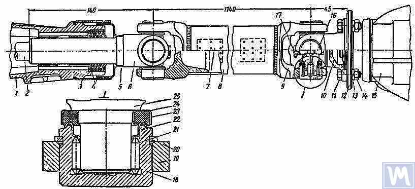
Figure 6. Driveshaft Assembly: 1 — gearbox extension; 2 — secondary shaft of the gearbox; 3 and 5 — dirt deflectors; 4 — rubber seals; 6 — sliding yoke; 7 — balancing plate; 8 — driveshaft tube; 9 — yoke; 10 — flange yoke; 11 — bolt; 12 — flange of the rear axle drive gear; 13 — spring washer; 14 — nut; 15 — rear axle; 16 — safety valve; 17 — angular grease fitting; 18 — needle bearing; 19 — yoke eye; 20 — spring retaining ring; 21 — needle; 22 — washer with toroidal end; 23 — cork ring; 24 — stamped cap; 25 — cross
The driveshaft, assembled with both universal joints, is carefully dynamically balanced at both ends by welding balancing plates (7) to the tube. Therefore, when disassembling the shaft, all its parts must be carefully marked so that they can be reassembled in their original positions. Failure to follow this instruction disrupts the shaft's balance, causing vibrations that can damage the transmission and vehicle body. If individual parts wear out, especially if the tube bends due to impact and it becomes impossible to dynamically balance the shaft after assembly, the entire shaft must be replaced.
Possible Driveshaft Malfunctions, Their Causes, and Solutions
| Cause of Malfunction | Solution |
|---|---|
| Driveshaft Vibration | |
| 1. Shaft bending due to an obstacle | 1. Straighten and dynamically balance the assembled shaft or replace the assembled shaft |
| 2. Bearing and cross wear | 2. Replace bearings and crosses and dynamically balance the assembled shaft |
| 3. Wear of extension bushings and sliding yoke | 3. Replace the extension and sliding yoke and dynamically balance the assembled shaft |
| Knocks When Starting and Coasting | |
| 1. Wear of sliding yoke splines or secondary gearbox shaft | 1. Replace worn parts. When replacing the sliding yoke, dynamically balance the assembled shaft |
| 2. Loose bolts securing the flange yoke to the rear axle drive gear flange | 2. Tighten bolts |
| Oil Throwing from Universal Joint Seals | |
| Wear of cork rings in universal joint seals | Replace cork rings, maintaining the relative position of all driveshaft parts during reassembly. If there is wear on crosses and bearings, replace the bearings and crosses and dynamically balance the assembled shaft |
3. Driveshaft Balancing
After repairing and assembling the driveshaft, it is dynamically balanced on a machine. One design of a balancing machine is shown in Figure 7. The machine consists of a plate (18), a pendulum frame (8) mounted on four vertical elastic rods (3), ensuring its oscillation in the horizontal plane. A bracket and front headstock (9), secured on a bracket (4), are mounted on the longitudinal tubes of the pendulum frame (8). The rear headstock (6) is on a movable traverse (5), allowing dynamic balancing of driveshafts of different lengths. The headstock spindles are mounted on precision ball bearings. The spindle of the front headstock (9) is driven by an electric motor installed in the machine base, through a V-belt drive and an intermediate shaft, on which a limb (10) (graduated disk) is mounted. Additionally, two stands (15) with retractable locking pins (17) are installed on the machine plate (18), ensuring the fixation of the front and rear ends of the pendulum frame depending on the balancing of the front or rear end of the driveshaft.
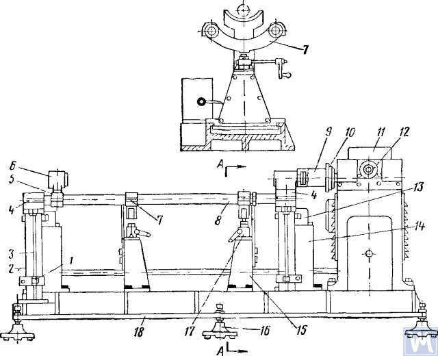
Figure 7. Dynamic Balancing Machine for Driveshafts
1—clamp; 2—dampers; 3—elastic rod; 4—bracket; 5—movable traverse; 6—rear headstock; 7—crossbar; 8—pendulum frame; 9—front driving headstock; 10—limb-disk; 11—millivoltmeter; 12—limb of the commutator-rectifier shaft; 13—magnetoelectric sensor; 14—fixed stand; 15—fixator stand; 16—support; 17—fixator; 18—support plate
The fixed stands (14) are mounted at the rear of the machine plate, and magnetoelectric sensors (13) are installed on them, with rods connected to the ends of the pendulum frame. To prevent resonance vibrations of the frame, dampers (2) filled with oil are installed under the brackets (4).
During dynamic balancing, the driveshaft assembly with the sliding yoke is installed and secured on the machine. One end of the driveshaft is connected by a flange-yoke to the flange of the front driving headstock, and the other end by the support neck of the sliding yoke to the splined sleeve of the rear headstock. Then the ease of rotation of the driveshaft is checked, and one end of the machine's pendulum frame is fixed using the fixator. After starting the machine, the limb of the rectifier is rotated counterclockwise, bringing the millivoltmeter needle to its maximum reading. The millivoltmeter reading corresponds to the magnitude of the imbalance. The millivoltmeter scale is graduated in gram-centimeters or grams of counterweight. Continuing to rotate the rectifier limb counterclockwise, the millivoltmeter reading is brought to zero, and the machine is stopped. Based on the rectifier limb reading, the angular displacement (angle of imbalance displacement) is determined, and by manually rotating the driveshaft, this value is set on the intermediate shaft limb. The welding place of the balancing plate will be on the top of the driveshaft, and the weighted part at the bottom in the correction plane. Then the balancing plate is attached and tied with thin wire at a distance of 10 mm from the weld, the machine is started, and the balance of the driveshaft end with the plate is checked. The imbalance should be no more than 70 g cm. Then, releasing one end and securing the other end of the pendulum frame with the fixator stand, dynamic balancing of the other end of the driveshaft is performed according to the technological sequence described above.
Driveshafts have some balancing features. For most parts, the base for dynamic balancing is the support necks (e.g., rotors of electric motors, turbines, spindles, crankshafts, etc.), but for driveshafts, it is the flanges. During assembly, there are unavoidable gaps in different connections leading to imbalance. If the minimum imbalance cannot be achieved during balancing, the shaft is rejected. The accuracy of balancing is influenced by the following factors:
- Gap in the connection between the landing belt of the driveshaft flange and the inner hole of the clamping flange of the left and right support headstocks;
- Radial and end runout of the base surfaces of the flange;
- Gaps in the hinge and splined connections. The presence of grease in the cavity of the splined connection can lead to “floating” imbalance. If it prevents achieving the required balancing accuracy, the driveshaft is balanced without grease.
Some imbalances may be completely uncorrectable. If increased friction is observed in the universal joints of the driveshaft, the mutual influence of the correction planes increases. This leads to a decrease in the performance and accuracy of balancing.
According to OST 37.001.053-74, the following imbalance standards are established: driveshafts with two joints (two-support) are balanced dynamically, and with three (three-support) – assembled with the intermediate support; the flanges (yokes) of driveshafts and couplings weighing more than 5 kg are statically balanced before assembling the shaft or coupling; the residual imbalance norms for driveshafts at each end or at the intermediate support of three-joint driveshafts are evaluated by specific imbalance;
The maximum permissible specific residual imbalance norm at each end of the shaft or at the intermediate support, as well as for three-joint driveshafts in any position on the balancing stand, should not exceed: for transmissions of passenger cars and small-load trucks (up to 1 t) and very small buses – 6 g-cm/kg, for the rest – 10 g-cm/kg. The maximum permissible residual imbalance norm of the driveshaft or three-joint driveshaft should be ensured on the balancing stand at a rotation frequency corresponding to their frequencies in the transmission at the maximum vehicle speed.
For driveshafts and three-joint driveshafts of trucks with a load capacity of 4 t and above, small and large buses, a reduction in the rotation frequency on the balancing stand to 70% of the transmission shafts' rotation frequency at the maximum vehicle speed is allowed. According to OST 37.001.053-74, the balancing rotation frequency of driveshafts should be equal to:
nb = (0.7 ... 1.0) nr,
where nb – balancing rotation frequency (should correspond to the main technical data of the stand, n=3000 min-1; nr – maximum working rotation frequency, min-1.
In practice, due to the gap in the joints and splined connections, the driveshaft cannot be balanced at the recommended rotation frequency. In this case, another rotation frequency is chosen, at which it balances.
4. Modern Balancing Machines for Driveshafts
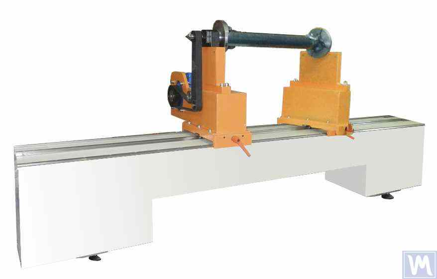
Figure 8. Balancing Machine for Driveshafts up to 2 Meters Long, Weighing up to 500 kg
The model has 2 stands and allows balancing in 2 correction planes.
Balancing Machine for Driveshafts up to 4200 mm Long, Weighing up to 400 kg
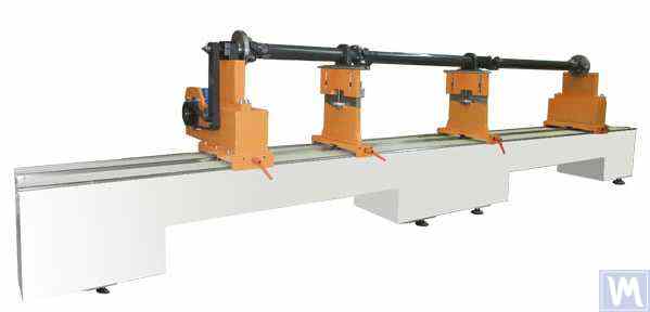
Figure 9. Balancing Machine for Driveshafts up to 4200 mm Long, Weighing up to 400 kg
The model has 4 stands and allows balancing in 4 correction planes simultaneously.
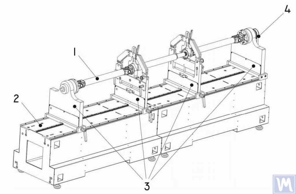
Figure 10. Horizontal Hard Bearing Balancing Machine for Dynamic Balancing of Driveshafts
1 – Balancing item (driveshaft); 2 – Machine base; 3 – Machine supports; 4 – Machine drive; The structural elements of the machine supports are shown in Figure 9.
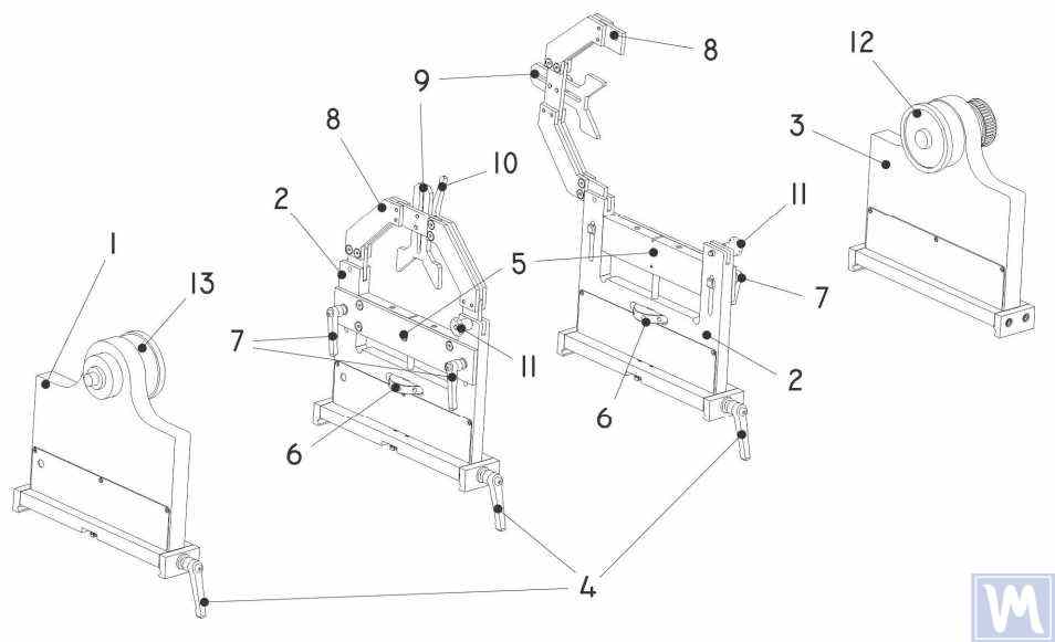
Figure 11. Machine Support Elements for Dynamic Balancing of Driveshafts
1 – Left non-adjustable support; 2 – Intermediate adjustable support (2 pcs.); 3 – Right non-adjustable fixed support; 4 – Support frame lock handle; 5 – Movable support platform; 6 – Support vertical adjustment nut; 7 – Vertical position lock handles; 8 – Support clamping bracket; 9 – Intermediate bearing movable clamp; 10 – Clamp lock handle; 11 – Clamping bracket lock; 12 – Drive (leading) spindle for item installation; 13 – Driven spindle
5. Preparation for Driveshaft Balancing
Below, we will consider the setup of the machine supports and the installation of the balancing item (four-support driveshaft) on the machine supports.
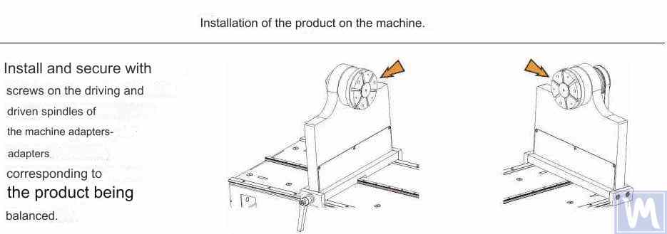
Figure 12. Installation of Transitional Flanges on the Spindles of the Balancing Machine
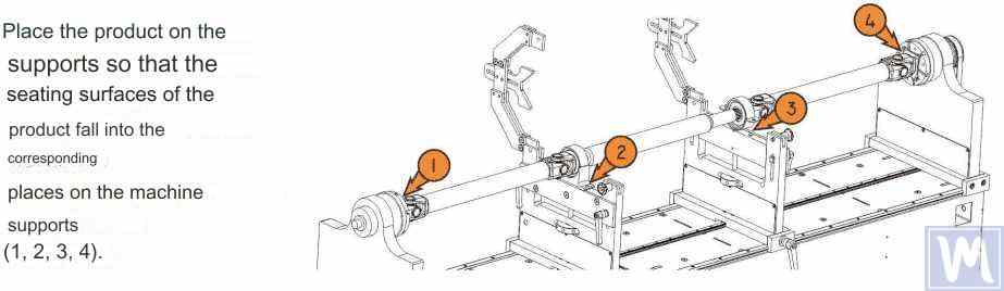
Figure 13. Installation of the Driveshaft on the Supports of the Balancing Machine
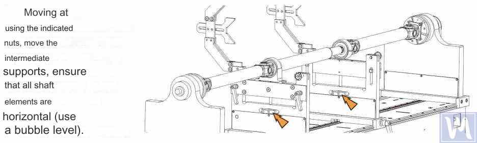
Figure 14. Leveling the Driveshaft Horizontally on the Supports of the Balancing Machine Using a Bubble Level
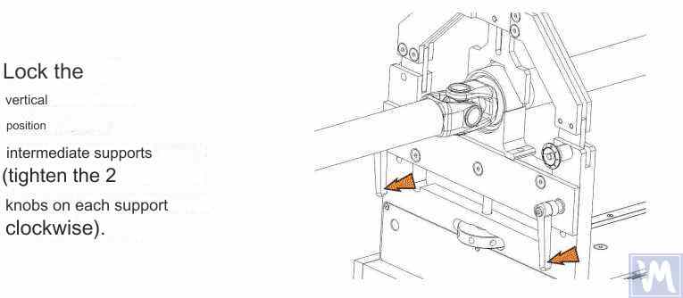
Figure 15. Fixing the Intermediate Supports of the Balancing Machine to Prevent Vertical Displacement of the Driveshaft
Rotate the item manually for a full turn. Ensure that it rotates freely and without jamming on the supports. After this, the mechanical part of the machine is set up, and the item installation is complete.
6. Driveshaft Balancing Procedure
The process of driveshaft balancing on the balancing machine will be considered using the Balanset-4 measuring system as an example. The Balanset-4 is a portable balancing kit designed for balancing in one, two, three, and four correction planes of rotors, either rotating in their own bearings or mounted on a balancing machine. The device includes up to four vibration sensors, a phase angle sensor, a four-channel measuring unit, and a portable computer.
The entire balancing process, including measurement, processing, and display of information on the magnitude and location of corrective weights, is performed automatically and does not require the user to have additional skills and knowledge beyond the provided instructions. The results of all balancing operations are saved in the Balancing Archive and can be printed as reports if necessary. In addition to balancing, the Balanset-4 can also be used as a regular vibro-tachometer, allowing measurement on four channels of the root mean square (RMS) value of total vibration, RMS of the rotational component of vibration, and control of rotor rotation frequency.
Furthermore, the device allows displaying graphs of the time function and vibration spectrum by vibration velocity, which can be useful in assessing the technical condition of the balanced machine.
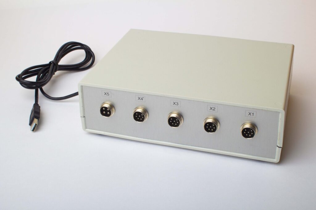
Figure 16. External View of the Balanset-4 Device for Use as a Measuring and Computing System of the Driveshaft Balancing Machine
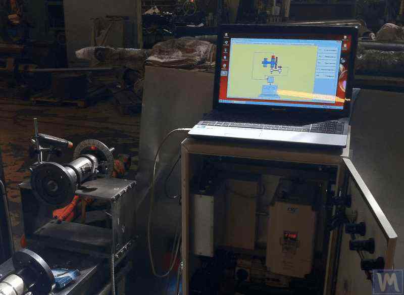
Figure 17. Example of Using the Balanset-4 Device as a Measuring and Computing System of the Driveshaft Balancing Machine
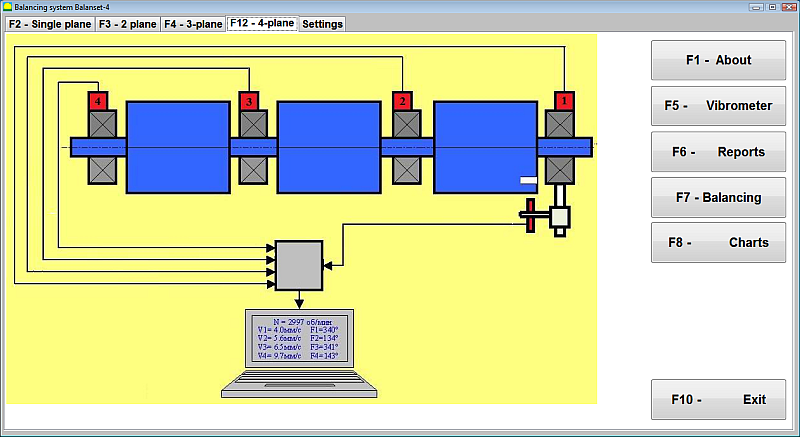
Figure 18. User Interface of the Balanset-4 Device
The Balanset-4 device can be equipped with two types of sensors – vibration accelerometers for measuring vibration (vibration acceleration) and force sensors. Vibration sensors are used for operating on post-resonance type balancing machines, while force sensors are used for pre-resonance type machines.
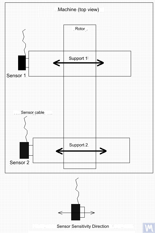
Figure 19. Installation of Balanset-4 Vibration Sensors on the Supports of the Balancing Machine
The direction of the sensors' sensitivity axis should match the direction of the support's vibration displacement, in this case – horizontal. For additional information on sensor installation, see BALANCING ROTORS IN OPERATING CONDITIONS. The installation of force sensors depends on the machine's design features.
- Install vibration sensors 1, 2, 3, 4 on the supports of the balancing machine.
- Connect the vibration sensors to connectors X1, X2, X3, X4.
- Install the phase angle sensor (laser tachometer) 5 so that the nominal gap between the radial (or end) surface of the balanced rotor and the sensor housing is in the range of 10 to 300 mm.
- Attach a reflective tape mark with a width of at least 10-15 mm to the rotor surface.
- Connect the phase angle sensor to connector X5.
- Connect the measuring unit to the computer’s USB port.
- When using mains power, connect the computer to the power supply unit.
- Connect the power supply unit to a 220 V, 50 Hz network.
- Turn on the computer and select the “BalCom-4” program.
- Press the “F12-four-plane” button (or the F12 function key on the computer keyboard) to select the mode for measuring vibration simultaneously in four planes using vibration sensors 1, 2, 3, 4, connected respectively to inputs X1, X2, X3, and X4 of the measuring unit.
- A mnemonic diagram illustrating the process of measuring vibration simultaneously on four measurement channels (or the process of balancing in four planes) appears on the computer display, as shown in Figure 16.
Before performing balancing, it is recommended to take measurements in the vibrometer mode (F5 button).
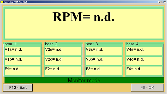
Figure 20. Vibrometer Mode Measurements
If the total vibration magnitude V1s (V2s) approximately matches the rotational component magnitude V1o (V2o), it can be assumed that the main contribution to the mechanism's vibration is due to rotor imbalance. If the total vibration magnitude V1s (V2s) significantly exceeds the rotational component V1o (V2o), it is recommended to inspect the mechanism – check the condition of the bearings, ensure secure mounting on the foundation, verify that the rotor does not contact stationary parts during rotation, and consider the influence of vibrations from other mechanisms, etc.
Studying the time function graphs and vibration spectra obtained in the "Graphs-Spectral Analysis" mode can be useful here.
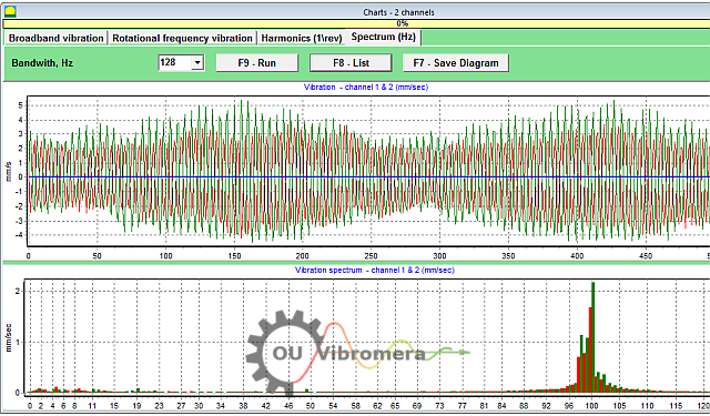
Figure 21. Vibration Time Function and Spectrum Graphs
The graph shows at which frequencies the vibration levels are highest. If these frequencies differ from the rotational frequency of the balanced mechanism's rotor, it is necessary to identify the sources of these vibration components and take measures to eliminate them before balancing.
It is also important to pay attention to the stability of the readings in vibrometer mode – the amplitude and phase of the vibration should not change by more than 10-15% during measurement. Otherwise, the mechanism might be operating near a resonance region. In this case, the rotor speed should be adjusted.
When performing four-plane balancing in "Primary" mode, five calibration runs and at least one verification run of the balanced machine are required. Vibration measurement during the first machine run without a trial weight is performed in the "Four-Plane Balancing" workspace. Subsequent runs are performed with a trial weight, sequentially installed on the driveshaft in each correction plane (in the area of each balancing machine support).
Before each subsequent run, the following steps should be taken:
- Stop the rotation of the balanced machine's rotor.
- Remove the previously installed trial weight.
- Install the trial weight in the next plane.
Figure 23. Four-Plane Balancing Workspace
After completing each measurement, the results of the rotor's rotation frequency (Nob), as well as the RMS values (Vo1, Vo2, Vo3, Vo4) and the phases (F1, F2, F3, F4) of the vibration at the rotational frequency of the balanced rotor are saved in the corresponding fields in the program window. After the fifth run (Weight in Plane 4), the "Balancing Weights" workspace (see Figure 24) appears, displaying the calculated values of the masses (M1, M2, M3, M4) and the installation angles (f1, f2, f3, f4) of the corrective weights that need to be installed on the rotor in four planes to compensate for its imbalance.
Figure 24. Workspace with Calculated Parameters of Corrective Weights in Four Planes
Attention! After completing the measurement process during the fifth run of the balanced machine, it is necessary to stop the rotor's rotation and remove the previously installed trial weight. Only after this can you proceed with installing (or removing) the corrective weights on the rotor.
The angular position for adding (or removing) the corrective weight on the rotor in the polar coordinate system is measured from the location of the trial weight installation. The angle measurement direction coincides with the rotor's rotation direction. In the case of balancing by blades, the blade of the balanced rotor conditionally considered as the 1st blade coincides with the trial weight installation location. The numbering direction of the blades indicated on the computer display follows the rotor's rotation direction.
In this version of the program, it is assumed by default that the corrective weight will be added to the rotor. This is indicated by the mark set in the "Add" field. If correcting the imbalance by removing the weight (e.g., by drilling) is necessary, set the mark in the "Remove" field using the mouse, after which the angular position of the corrective weight will automatically change by 180 degrees.
After installing the corrective weights on the balanced rotor, press the "Exit – F10" button (or the F10 function key on the computer keyboard) to return to the previous "Four-Plane Balancing" workspace and check the effectiveness of the balancing operation. After completing the verification run, the results of the rotor's rotation frequency (Nob) and the RMS values (Vo1, Vo2, Vo3, Vo4) and phases (F1, F2, F3, F4) of the vibration at the rotational frequency of the balanced rotor are saved. Simultaneously, the "Balancing Weights" workspace (see Figure 21) appears over the "Four-Plane Balancing" workspace, displaying the calculated parameters of additional corrective weights that need to be installed (or removed) on the rotor to compensate for its residual imbalance. Additionally, this workspace shows the values of the residual imbalance achieved after balancing. If the values of residual vibration and/or residual imbalance of the balanced rotor meet the tolerance requirements specified in the technical documentation, the balancing process can be completed. Otherwise, the balancing process can be continued. This method allows for correcting possible errors through successive approximations that may occur when installing (removing) the corrective weight on the balanced rotor.
If the balancing process continues, additional corrective weights must be installed (or removed) on the balanced rotor according to the parameters specified in the "Balancing Weights" workspace.
The "Coefficients – F8" button (or the F8 function key on the computer keyboard) is used to view and save in the computer's memory the rotor balancing coefficients (dynamic influence coefficients) calculated from the results of the five calibration runs.
7. Recommended Balancing Accuracy Classes for Rigid Rotors
Table 2. Recommended Balancing Accuracy Classes for Rigid Rotors.

Recommended Balancing Accuracy Classes for Rigid Rotors
| Types of Machines (Rotors) | Balancing Accuracy Class | Value eper Ω mm/s |
|---|---|---|
| Drive crankshafts (structurally unbalanced) for large low-speed marine diesel engines (piston speed less than 9 m/s) | G 4000 | 4000 |
| Drive crankshafts (structurally balanced) for large low-speed marine diesel engines (piston speed less than 9 m/s) | G 1600 | 1600 |
| Drive crankshafts (structurally unbalanced) on vibration isolators | G 630 | 630 |
| Drive crankshafts (structurally unbalanced) on rigid supports | G 250 | 250 |
| Reciprocating engines assembled for passenger cars, trucks, and locomotives | G 100 | 100 |
| Automobile parts: wheels, wheel rims, wheelsets, transmissions | ||
| Drive crankshafts (structurally balanced) on vibration isolators | G 40 | 40 |
| Agricultural machines | G 16 | 16 |
| Drive crankshafts (balanced) on rigid supports | ||
| Crushers | ||
| Drive shafts (driveshafts, screw shafts) | ||
| Aircraft gas turbines | G 6.3 | 6.3 |
| Centrifuges (separators, settlers) | ||
| Electric motors and generators (with a shaft height of at least 80 mm) with a maximum nominal rotation speed of up to 950 min-1 | ||
| Electric motors with a shaft height of less than 80 mm | ||
| Fans | ||
| Gear drives | ||
| General-purpose machines | ||
| Metal cutting machines | ||
| Papermaking machines | ||
| Pumps | ||
| Turbochargers | ||
| Water turbines | ||
| Compressors | ||
| Computer-controlled drives | G 2.5 | 2.5 |
| Electric motors and generators (with a shaft height of at least 80 mm) with a maximum nominal rotation speed over 950 min-1 | ||
| Gas and steam turbines | ||
| Metal cutting machine drives | ||
| Textile machines | ||
| Audio and video equipment drives | G 1 | 1 |
| Grinding machine drives | ||
| Spindles and drives of high-precision equipment | G 0.4 | 0.4 |
Frequently Asked Questions about Drive Shaft Balancing
What is drive shaft balancing?
Drive shaft balancing is the process of correcting any mass imbalance in a drive shaft so that it rotates smoothly without causing vibrations. This involves measuring where the shaft is heavier on one side and then adding or removing small amounts of weight (for example, welding on balancing weights) to counteract that imbalance. A balanced drive shaft runs evenly, which prevents excessive vibration and wear on vehicle components.
Why is drive shaft balancing important?
An unbalanced drive shaft can lead to strong vibrations, especially at certain speeds, and may cause clunking noises during acceleration or gear shifts. Over time, these vibrations can damage bearings, universal joints, and other drivetrain components. Balancing the drive shaft eliminates these vibrations, ensuring a smoother ride, reducing strain on parts, and preventing costly damage or downtime.
What are common symptoms of an unbalanced drive shaft?
The typical symptoms of an unbalanced or faulty drive shaft include noticeable vibration or shuddering felt in the vehicle floor or seat, particularly as speed increases. You might also hear knocking or rattling sounds when shifting gears or during acceleration and deceleration. In some cases, the universal joint may overheat due to imbalance. If you observe these signs, it's likely the drive shaft needs balancing or repair.
How do you balance a drive shaft?
Drive shaft balancing is usually done using a specialized balancing machine. The drive shaft is mounted and spun at high speed while sensors detect any imbalance. A technician then attaches small weights to the drive shaft (or removes material) at specific positions based on the machine's readings. This process is repeated until the drive shaft rotates without significant vibration. Modern systems like the Balanset-4 can guide this process and calculate exactly where and how much weight to add for precise balancing.
Conclusion
In conclusion, proper drive shaft balancing is essential for safety, performance, and cost savings. By detecting and correcting imbalance, you prevent unnecessary wear on parts, avoid damaging breakdowns, and maintain optimal machine performance. Modern balancing systems like our Balanset-1 and Balanset-4 devices make the process efficient, helping even small workshops achieve professional results.
If you're facing persistent driveshaft vibrations or need a reliable balancing solution, don't hesitate to act. Apply the steps outlined in this guide or consult with our experts for assistance. With the right approach and equipment, you can ensure your driveshaft runs smoothly and reliably for years to come. Contact us to learn more or to explore the best drive shaft balancing equipment for your needs.
0 Comments