ドライブシャフトのバランス調整:総合ガイド
ドライブシャフトを自分でバランシング — 車載のまま、取り外し不要
Balanset-1Aは2平面ポータブルバランサーである—振動センサー、レーザータコメーター、ソフトウェアが1つのキットにまとまっている。自動車のドライブシャフトのほか、ファン、フライホイール、破砕機、その他自身のベアリングで回転するあらゆるローターのバランシングが可能である。2年保証、DHL / UPSによる世界配送、サブスクリプション不要。
トラックを運転していて、加速時やギアチェンジ時に突然激しい振動を感じたり、大きな異音が聞こえたりしたと想像してみてください。これは単なる不快感ではありません。ドライブシャフトのバランスが崩れている兆候かもしれません。エンジニアや整備士にとって、このような振動や異音は効率の低下、部品の摩耗の加速、そして放置すれば高額なダウンタイムにつながる可能性を示唆しています。
車両の作業をしていますか? こちらをご覧ください: 取り外し不要の車載ドライブシャフトバランシング.
車載ドライブシャフトのバランシング:実際の作業を、手順を追って解説
以下の写真は、車両をリフトに乗せた状態で実際に行われたバランシング作業のものである。ドライブシャフトは一度も取り外されていない—センサーは車両本体に取り付けられ、シャフトはドライブトレインを通じてエンジンによって回転させられ、補正ウェイトは下側から取り付けられる。これにより、シャフトは自身のベアリングと本来の作動角度を保ったままとなり、結果は組み立て体が実際にどのように動作するかを反映する—ベンチ式バランシングマシンでは完全には再現できないものである。
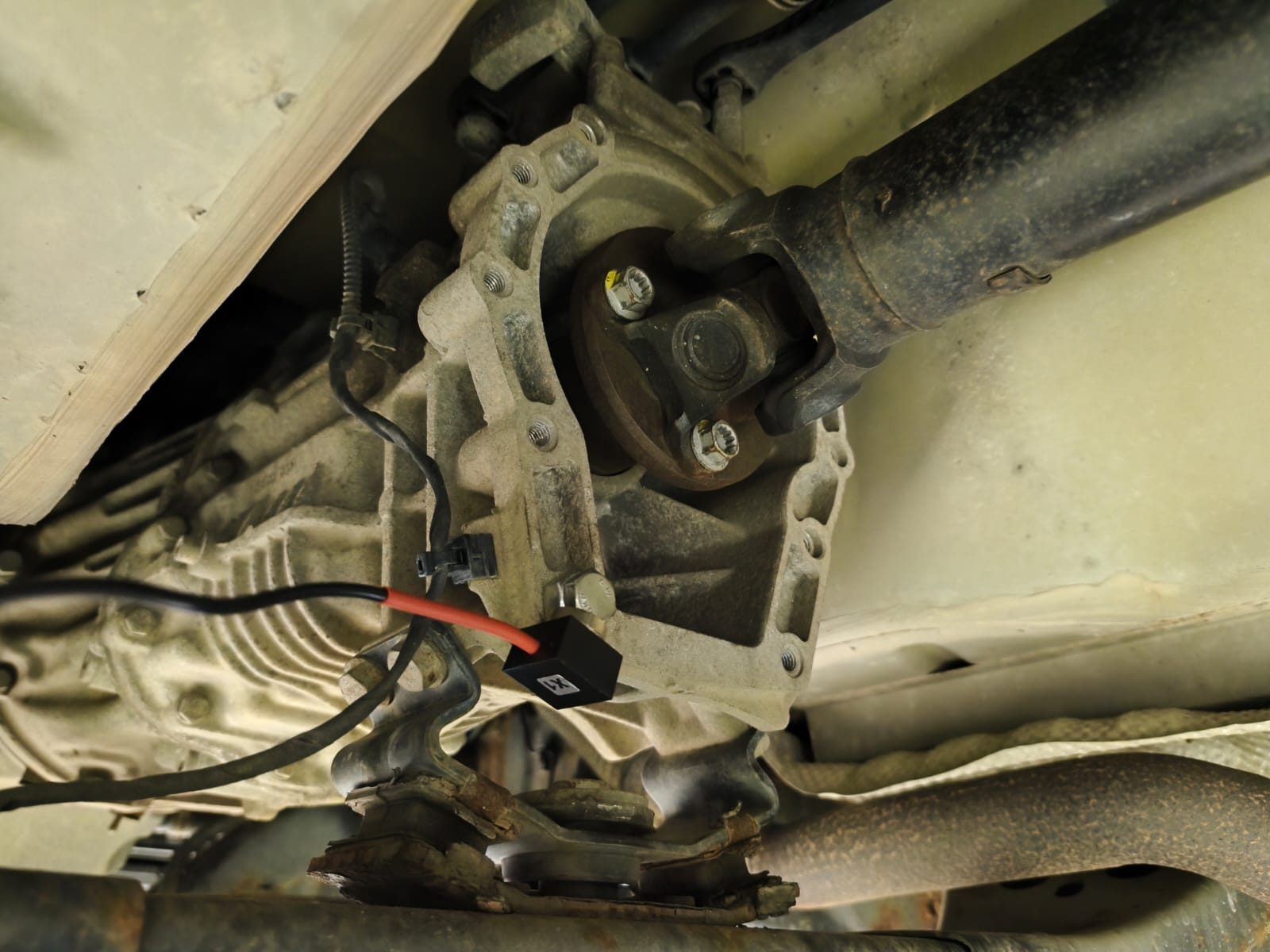
図24。ファイナルドライブハウジングに、ドライブシャフト支持ベアリングにできるだけ近い位置で取り付けられた振動センサー。
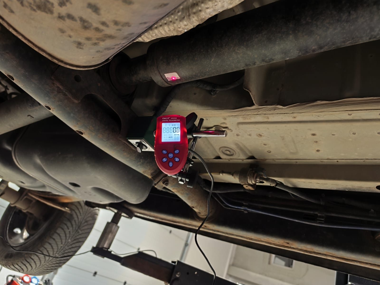
図25。シャフトに貼られた反射テープに向けたレーザータコメーター — 回転速度とアンバランスの位相角の両方を提供します。
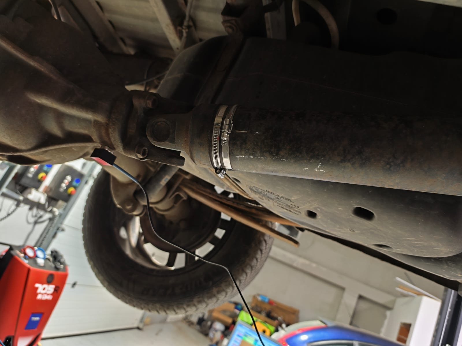
図26。ソフトウェアが計算した角度と質量で、ステンレス製ホースクランプによりシャフトチューブに固定された補正おもり。
センサーの設置、安全な試運転、試しおもり、残留振動の確認を含む詳細な手順は、次で説明されています 取り外し不要の車載ドライブシャフトバランシング.
この包括的なガイドでは、ドライブシャフトのバランス調整に関する実用的なソリューションをご紹介します。ドライブシャフトとは何か、なぜバランス調整が必要なのか、振動や異音の原因となる一般的な不具合を認識し、ドライブシャフトのダイナミックバランス調整の明確な手順をステップバイステップで解説します。これらのベストプラクティスを適用することで、修理費用を節約し、トラブルシューティングの時間を短縮し、機械や車両が振動を最小限に抑えて確実に動作することを保証します。
目次
- 1.ドライブシャフトの種類
- 2.ユニバーサル・ジョイント・ドライブの故障
- 3.ドライブシャフトのバランシング
- 4.ドライブシャフト用の最新のバランシングマシン
- 5.ドライブシャフトのバランシングの準備
- 6. ドライブシャフトのバランス調整方法:ステップバイステップの手順
- 7.リジッドローターの推奨バランシング精度クラス
1.ドライブシャフトの種類
ユニバーサルジョイントドライブ(ドライブシャフト)は、ユニバーサルジョイントの中心で交差し、互いに角度を持って相対移動できるシャフト間でトルクを伝達する機構です。車両では、ドライブシャフトは、古典的または全輪駆動構成の場合、ギアボックス(またはトランスファーケース)から従動車軸にトルクを伝達します。全輪駆動車の場合、ユニバーサルジョイントは通常、ギアボックスの従動シャフトをトランスファーケースの駆動シャフトに接続し、トランスファーケースの従動シャフトを従動車軸のメインドライブの駆動シャフトに接続します。
フレームに搭載されたユニット(ギアボックスやトランスファーケースなど)は、支持部およびフレーム自体の変形により、互いに相対的に動く可能性があります。一方、ドライブアクスルはサスペンションを介してフレームに接続されており、サスペンションの弾性要素の変形により、フレームおよびそこに搭載されたユニットに対して相対的に動く可能性があります。この動きは、ユニットを接続するドライブシャフトの角度だけでなく、ユニット間の距離も変化させる可能性があります。
ユニバーサルジョイントドライブには重大な欠点がある。それはシャフトの回転が不均一になることである。一方のシャフトが均一に回転しても、他方は均一に回転せず、この不均一さはシャフト間の角度が大きくなるほど増大する。この制約により、ユニバーサルジョイントドライブは、旋回する車輪へのトルク伝達が主な課題となる前輪駆動車の伝動系など、多くの用途で使用できない。この欠点は、中間シャフトの両端のヨークを同一平面上に配置し(位相を揃え)、等しいジョイント角(γ1 = γ2)で2つのユニバーサルジョイントを1本のシャフトに使用することで部分的に補償できる。ヨークを90°ずらして配置しても速度変動は相殺されず、むしろ増大する。しかし、均一な回転が求められる用途では、通常、等速ジョイント(CVジョイント)が代わりに使用される。CVジョイントは、同じ目的を果たすより高度で複雑な設計である。
ユニバーサル・ジョイント・ドライブは、ドライブシャフトと中間サポートによって接続された1つまたは複数のユニバーサル・ジョイントで構成されます。
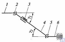
図1.ユニバーサル・ジョイント・ドライブの図:1、4、6...ドライブシャフト、2、5...ユニバーサルジョイント、3...コンペンセーティングコネクション、u1、u2...シャフト間の角度
一般に、ユニバーサルジョイントドライブは、ユニバーサルジョイント2と5、ドライブシャフト1、4、6、および補償接続3で構成されます。ドライブシャフトは、車両フレームのクロスメンバーに取り付けられた中間サポートに取り付けられる場合があります。ユニバーサルジョイントは、軸が斜めに交差するシャフト間のトルク伝達を保証します。ユニバーサルジョイントは、不等速タイプと等速タイプに分けられます。不等速ジョイントはさらに、弾性タイプと剛性タイプに分類されます。等速ジョイントには、分割溝付きボールタイプ、分割レバー付きボールタイプ、およびカムタイプがあります。これらは通常、制御される前輪のドライブに取り付けられ、シャフト間の角度は45°に達することがあり、ユニバーサルジョイントの中心は、ホイールの回転軸と旋回軸の交点と一致する必要があります。
弾性ユニバーサルジョイントは、連結要素の弾性変形により、軸が2~3°の角度で交差するシャフト間でトルクを伝達する。剛性の非等速ジョイントは、剛性部品の可動連結によって、あるシャフトから別のシャフトへトルクを伝達する。これは2つのヨーク—3と5—から構成され、その円筒形の穴には、連結要素であるクロス4の端部A、B、C、Dがベアリングを介して取り付けられている。ヨークはシャフト1および2に剛結されている。ヨーク5はクロスの軸B–Dを中心に回転でき、同時にクロスとともに軸A–Cを中心に回転することができ、それによって、シャフト間の角度を変化させながら一方のシャフトから他方のシャフトへ回転を伝達することができる。
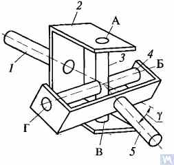
図2.剛性不均一速度ユニバーサルジョイントの図
シャフト1がその軸まわりに角度αだけ回転すると、同じ時間内にシャフト2は角度βだけ回転します。シャフト1とシャフト2の回転角度の関係は、次の式で表されます tanα = tanβ × cosγ、γはシャフトの軸が成す角度である。この式は、角度βが角度αより小さくなったり、等しくなったり、大きくなったりすることを示している。これらの角度が等しくなるのは、シャフト1が90°回転するごとである。したがって、シャフト1が均一に回転していても、シャフト2の角速度は不均一であり、正弦則に従って変化する。シャフト2の回転の不均一さは、シャフト軸間の角度γが大きくなるほど顕著になる。
シャフト2の不均一な回転がユニットのシャフトに伝達されると、伝達時にさらなる脈動荷重が発生し、角度γとともに増加する。シャフト2の不均一な回転がユニットのシャフトに伝達されるのを防ぐために、ユニバーサルジョイント駆動では2つのユニバーサルジョイントが使用される。これらは角度γ1とγ2が等しくなるように設置され、不均一に回転するシャフト4に固定されたユニバーサルジョイントのフォークは同一平面上に配置される必要があります。
ユニバーサルジョイントドライブの主要部品の設計を図3に示します。不等速ユニバーサルジョイントは、クロス(3)で接続された2つのヨーク(1)で構成されています。ヨークの1つにはフランジが付いている場合があり、もう1つはドライブシャフトチューブに溶接されているか、ドライブシャフトに接続するためのスプライン端(6)(またはスリーブ)が付いています。クロスのトラニオンは、ニードルベアリング(7)の両方のヨークのアイに取り付けられています。各ベアリングはケース(2)に収納され、ヨークのアイにキャップで保持されます。キャップは、ワッシャーのタブで固定された2本のボルトでヨークに接続されています。場合によっては、ベアリングはスナップリングでヨークに固定されます。ベアリング内の潤滑を維持し、水や汚れから保護するために、ゴム製のセルフタイトシールが使用されています。クロスの内部キャビティには、ベアリングに達するグリースフィッティングを介してグリースが充填されています。クロスには通常、グリースがクロスに注入される際の圧力によるシールの損傷を防ぐ安全弁が備えられています。スプライン接続部(6)は、グリースフィッティング(5)によって潤滑されます。
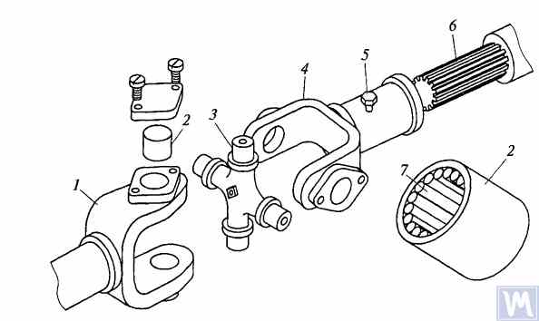
図3.剛性不均一速度ユニバーサルジョイントの詳細
剛性の非等速ユニバーサルジョイントで連結されたシャフトの軸間の最大角度は、通常20°を超えない。角度が大きくなると効率が大幅に低下するためである。シャフト軸間の角度が0~2°の範囲で変動する場合、クロスのトラニオンがニードルベアリングによって変形し、ユニバーサルジョイントが早期に故障する原因となる。
高速履帯車両のトランスミッションでは、軸が最大 1.5 ~ 2° の角度で交差するシャフト間でトルクを伝達できるギア カップリング タイプのユニバーサル ジョイントがよく使用されます。
ドライブシャフトは通常、特殊鋼のシームレスまたは溶接チューブを使用して管状に作られています。ユニバーサルジョイントのヨーク、スプラインスリーブ、またはチップはチューブに溶接されています。ドライブシャフトに作用する横荷重を軽減するため、ユニバーサルジョイントを組み立てた状態でダイナミックバランシングを行います。アンバランスは、バランシングプレートをドライブシャフトに溶接するか、ユニバーサルジョイントのベアリングキャップの下にバランシングプレートを取り付けることによって修正されます。工場でのユニバーサルジョイントドライブの組み立てとバランシング後のスプライン接続部品の相対位置は、通常特別なラベルでマークされます。
ユニバーサルジョイントドライブのコンペンセーティングコネクションは、通常スプラインコネクションの形で作られ、ユニバーサルジョイントドライブ部品の軸方向の動きを可能にします。これは、ユニバーサルジョイントドライブのスプラインスリーブに嵌合するスプラインチップで構成されています。潤滑は、グリース継手を介してスプライン接続部に導入されるか、組み立て時に塗布され、車両の長期使用後に交換されます。グリースの漏れや汚染を防ぐために、一般的にシールとカバーが取り付けられています。
長いドライブシャフトの場合、ユニバーサルジョイントドライブには通常中間サポートが使用されます。中間サポートは通常、車両フレームのクロスメンバにボルトで固定されたブラケットで構成され、その中にボールベアリングがゴム製の弾性リングに取り付けられている。ベアリングは両側がキャップで密閉され、潤滑装置が付いています。ゴム製の弾性リングは、フレームの変形によって生じる可能性のある組み立ての不正確さやベアリングのずれを補正するのに役立ちます。
ニードルベアリング付きユニバーサルジョイント(図4a)は、ヨーク、クロス、ニードルベアリング、シールで構成されている。ニードルベアリング付きカップは、クロスのトラニオンに取り付けられ、シールで密封される。カップはスナップリングまたはキャップでヨークに固定され、ネジで固定される。ユニバーサルジョイントの潤滑は、クロスの内部ドリルからグリース継手を介して行われます。安全弁は、ジョイント内の過剰な油圧を除去するために使用されます。駆動ヨークが均一に回転している間、従動ヨークは不均一に回転します:1回転に2回、駆動ヨークより進んだり遅れたりします。不均一な回転をなくし、慣性荷重を減らすために、2つのユニバーサルジョイントが使用される。
前駆動輪への駆動には、等速ユニバーサルジョイントが取り付けられている。GAZ-66およびZIL-131車両の等速ジョイント駆動は、ヨーク2、5(図4b)、4つのボール7、および中央のボール8で構成されています。駆動ヨーク2は内側のアクスルシャフトと一体であり、従動ヨークは外側のアクスルシャフトと一緒に鍛造され、その先端にホイールハブが固定されています。ヨーク2からヨーク5への駆動モーメントは、ヨークの円形溝に沿って動くボール7を介して伝達されます。中央のボール8はヨークの中心を決める役割を果たし、スタッド3、4によって固定されています。ヨーク2、5の回転周波数は、ヨークに対する機構の対称性により同じです。シャフトの長さの変更は、ヨークとシャフトの自由スプライン接続によって保証されます。
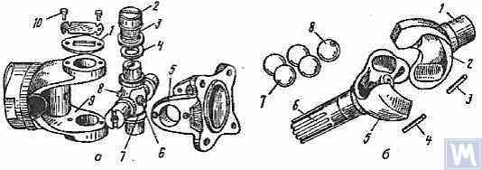
図 4.ユニバーサルジョイント: a - ユニバーサルジョイント: 1 - キャップ; 2 - カップ; 3 - ニードルベアリング; 4 - シール; 5, 9 - ヨーク; 6 - 安全バルブ; 7 - クロス; 8 - グリースフィッティング; 10 - ねじ; b - 等速ユニバーサルジョイント: 1 - インナーアクスルシャフト; 2 - 駆動ヨーク; 3, 4 - スタッド; 5 - 従動ヨーク; 6 - アウターアクスルシャフト; 7 - ボール; 8 - 中央ボール
2.ユニバーサル・ジョイント・ドライブの故障
ユニバーサル・ジョイント・ドライブの不具合は、通常、車両の走行中、特にギア間のシフトチェンジやエンジン・クランクシャフト・スピードの急激な上昇時(例えば、エンジン・ブレーキから加速への移行時)に発生するユニバーサル・ジョイントの鋭いノックとして現れます。ユニバーサルジョイントの故障の兆候として、高温(100℃以上)への加熱が考えられます。これは、ユニバーサルジョイントのブッシュやトラニオン、ニードルベアリング、クロス、スプライン接続部が著しく摩耗し、ユニバーサルジョイントのミスアライメントやニードルベアリングへの大きな衝撃アキシャル荷重が発生するために起こります。ユニバーサルジョイントのクロスのコルクシールの損傷は、トラニオンとそのベアリングの急速な摩耗につながります。
メンテナンスの際、ユニバーサルジョイントドライブは、ドライブシャフトを手で両方向に鋭く回転させてチェックします。シャフトの自由回転の程度によって、ユニバーサルジョイントとスプライン接続部の摩耗が決まる。8~10,000キロメートルごとに、ギアボックスのドリブン・シャフト・フランジとメイン・トランスミッション・ギアのドライブ・シャフトとエンド・ユニバーサル・ジョイントのフランジとのボルト接続の状態、およびドライブ・シャフトの中間サポートの締め付けを点検する。スプライン接続部のラバーブーツとユニバーサルジョイントクロスのコルクシールの状態もチェックする。すべての締め付けボルトは完全に締め付けること(締め付けトルク8~10kgf-m)。
ユニバーサルジョイントのニードルベアリングは、トランスミッションユニットに使用される液体オイルで潤滑される。ほとんどの車両のスプライン接続部は、グリース(US-1、US-2、1-13など)で潤滑される。ニードルベアリングの潤滑にグリースを使用することは固く禁じられている。一部の車両では、スプライン接続部はトランスミッションオイルで潤滑される。中間サポートベアリングは、ゴムスリーブに取り付けられており、工場での組み立て時に潤滑されるため、実質的に潤滑の必要はない。ZIL-130車両のサポートベアリングには、定期メンテナンス時(1100~1700kmごと)に圧力継手からグリースが注入されます。
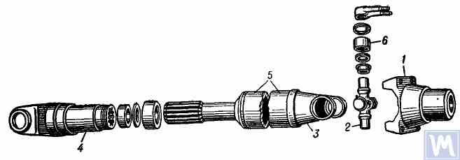
図5.ユニバーサルジョイントドライブ:1...ドライブシャフト固定用フランジ、2...ユニバーサルジョイントクロス、3...ユニバーサルジョイントヨーク、4...スライディングヨーク、5...ドライブシャフトチューブ、6...ニードルローラーベアリング(クローズドエンド付き
ユニバーサルジョイントドライブは、中空シャフトで接続されたニードルベアリング付き2つのユニバーサルジョイントと、インボリュートスプライン付きスライディングヨークで構成されています。汚れから確実に保護し、スプライン接続部に良好な潤滑を提供するため、ギアボックスのセカンダリシャフト(2)に接続されたスライディングヨーク(6)は、ギアボックスハウジングに取り付けられた延長部(1)に配置されています。さらに、スプライン接続部のこの位置(ジョイント間のゾーンの外側)は、ユニバーサルジョイントドライブの剛性を著しく高め、摺動スプライン接続部が磨耗したときのシャフト振動の可能性を低減します。
ドライブシャフトは薄肉の電気溶接管(8)で作られており、両端に同一のヨーク(9)が圧入され、アーク溶接されている。クロス(25)のニードルベアリングハウジング(18)はヨーク(9)のアイに圧入され、スプリング保持リング(20)で固定されている。各ユニバーサルジョイントベアリングには22本のニードル(21)が含まれている。スタンプキャップ(24)は、クロスの突出したトラニオンに圧入され、コルクリング(23)が取り付けられている。ベアリングは、クロス中央のねじ穴にねじ込まれた角度付きグリースフィッティング(17)によって潤滑され、クロスのトラニオンの貫通チャネルに接続されている。ユニバーサルジョイントクロスの反対側には、中央に安全弁(16)が設けられています。この安全弁は、クロスとベアリングへのグリース充填時に余分なグリースを排出し、作動中にクロス内部の圧力上昇を防ぐように設計されています(この弁は約3.5 kg/cm²の圧力で作動します)。安全弁を設ける必要があるのは、クロス内部の過度の圧力上昇がコルクシールの損傷(押し出し)につながる可能性があるためです。
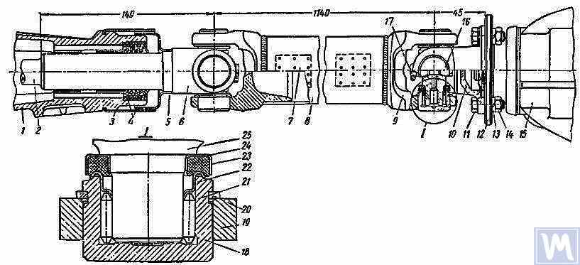
図6.ドライブシャフトアセンブリ:1...ギアボックスの延長部、2...ギアボックスのセカンダリシャフト、3および5...ダートディフレクタ、4...ゴムシール、6...スライディングヨーク、7...バランスプレート、8...ドライブシャフトチューブ、9...ヨーク、10...フランジヨーク、11...ボルト、12...リアアクスルドライブギアのフランジ;13...スプリングワッシャー; 14...ナット; 15...リアアクスル; 16...安全バルブ; 17...アンギュラーグリースフィッティング; 18...ニードルベアリング; 19...ヨークアイ; 20...スプリングリテーニングリング; 21...ニードル; 22...トロイダルエンドワッシャー; 23...コルクリング; 24...スタンプキャップ; 25...クロス
両方のユニバーサルジョイントが組み込まれたドライブシャフトは、両端でバランスプレート(7)をチューブに溶接することで、慎重に動的バランスが取られています。したがって、シャフトを分解する際には、すべての部品を元の位置に再組み立てできるように、注意深くマーキングする必要があります。この指示に従わないと、シャフトのバランスが崩れ、振動が発生し、トランスミッションや車体に損傷を与える可能性があります。個々の部品が摩耗した場合、特に衝撃によってチューブが曲がり、組み立て後にシャフトの動的バランスが取れなくなった場合は、シャフト全体を交換する必要があります。
ドライブシャフトに起こりうる故障とその原因、解決策
| 故障の原因 | ソリューション |
|---|---|
| ドライブシャフトの振動 | |
| 1.障害物によるシャフトの曲がり | 1.組み立てられたシャフトをまっすぐにし、動的バランスをとるか、組み立てられたシャフトを交換する。 |
| 2.ベアリングとクロスの摩耗 | 2.ベアリングとクロスを交換し、組み立てたシャフトの動的バランスをとる。 |
| 3.エクステンションブッシュとスライディングヨークの摩耗 | 3.エクステンションとスライディングヨークを交換し、組み立てたシャフトの動的バランスをとる。 |
| 発進時および惰性走行時のノック | |
| 1.スライディングヨークスプラインまたはセカンダリギアボックスシャフトの摩耗 | 1.摩耗した部品を交換する。スライディング・ヨークを交換する際は、組み立てたシャフトの動的バランスをとる。 |
| 2.フランジヨークをリアアクスルドライブギアの フランジに固定しているボルトの緩み。 | 2.ボルトを締める |
| ユニバーサルジョイントシールからのオイルスロー | |
| ユニバーサルジョイントのシールにおけるコルクリングの摩耗 | 再組み立ての際、すべてのドライブシャフト部品の相対位置を維持しながら、コルクリングを交換する。クロスとベアリングに摩耗がある場合は、ベアリングとクロスを交換し、組み立てたシャフトの動的バランスをとる。 |
3.ドライブシャフトのバランシング
ドライブシャフトを修理して組み立てた後、機械で動的にバランスをとる。バランシングマシンの設計のひとつを図7に示す。マシンは、プレート(18)、4本の垂直弾性ロッド(3)に取り付けられた振り子フレーム(8)で構成され、水平面内での振動を保証します。ブラケット(4)に固定されたブラケットと前部主軸台(9)は、振り子フレーム(8)の縦管に取り付けられている。後部主軸台(6)は可動トラバース(5)上にあり、異なる長さのドライブシャフトの動的バランスをとることができます。主軸台スピンドルは精密ボールベアリングに取り付けられています。フロント主軸台(9)のスピンドルは、マシンベースに設置された電気モーターによって、Vベルトドライブと中間シャフトを介して駆動され、その上にリム(10)(目盛盤)が取り付けられています。さらに、格納式ロックピン(17)を備えた2つのスタンド(15)がマシンプレート(18)上に設置され、ドライブシャフトの前端または後端のバランスに応じて振り子フレームの前端と後端の固定を保証します。
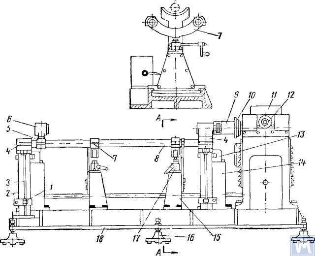
図7.ドライブシャフト用のダイナミックバランシングマシン
1-クランプ、2-ダンパー、3-弾性ロッド、4-ブラケット、5-可動式トラバース、6-後主軸台、7-クロスバー、8-振り子フレーム、9-前主軸台、10-リムディスク、11-ミリボルトメーター、12-整流子-整流子軸のリム、13-磁気センサー、14-固定スタンド、15-固定台、16-サポート、17-固定台、18-支持板
固定スタンド(14)はマシンプレートの後部に取り付けられ、その上に磁電センサー(13)が設置され、ロッドが振り子フレームの両端に接続されている。フレームの共振振動を防ぐため、ブラケット(4)の下にはオイルを満たしたダンパー(2)が取り付けられている。
動的バランス調整では、スライディングヨークを備えたドライブシャフトアセンブリがマシンに取り付けられ、固定されます。ドライブシャフトの一端はフランジヨークによって前部駆動ヘッドストックのフランジに接続され、他端はスライディングヨークのサポートネックによって後部ヘッドストックのスプラインスリーブに接続されます。次に、ドライブシャフトの回転の容易さがチェックされ、マシンの振り子フレームの一端が固定具を使用して固定されます。マシンを起動した後、整流器のリムを反時計回りに回転させ、ミリボルトメーターの針が最大読み取り値になるようにします。ミリボルトメーターの読み取り値は、アンバランスの大きさに対応します。ミリボルトメーターの目盛りは、グラムセンチメートルまたはカウンターウェイトのグラム単位で目盛りが付けられています。整流器のリムを反時計回りに回転させ続けると、ミリボルトメーターの読み取り値がゼロになり、マシンが停止します。整流器のリムの読み取り値に基づいて、角度変位(アンバランス変位角度)が決定され、ドライブシャフトを手動で回転させることにより、この値が中間シャフトのリムに設定されます。バランスプレートの溶接箇所はドライブシャフトの上部にあり、加重部分は補正面の下部にあります。次に、バランスプレートを取り付け、溶接部から10 mmの距離で細いワイヤーで結び、機械を起動して、ドライブシャフトの端とプレートのバランスを確認します。アンバランスは70 g·cm(700 g·mm)以下である必要があります。次に、振り子フレームの一端を解放し、他端を固定スタンドで固定し、上記の技術手順に従ってドライブシャフトの他端の動的バランス調整を実行します。
ドライブシャフトにはいくつかのバランシング機能があります。ほとんどの部品では、ダイナミックバランシングのベースはサポートネック(電気モーターのローター、タービン、スピンドル、クランクシャフトなど)ですが、ドライブシャフトの場合はフランジです。組み立ての際、さまざまな接続部に避けられない隙間が生じ、アンバランスが生じます。バランシング中に最小のアンバランスを達成できない場合、シャフトは不合格になります。バランシングの精度は、以下の要因に影響されます:
- ドライブシャフト・フランジのランディング・ベルトと左右のサポート・ヘッドストックのクランプ・フランジの内孔との接続部に隙間があること;
- フランジのベース面の半径方向および端部の振れ;
- ヒンジとスプライン接続部の隙間。スプライン接続部の空洞にグリースが存在すると、「浮き上がり」のような不均衡が生じる可能性があります。必要なバランス調整精度の達成を妨げる場合は、グリースを塗布せずにドライブシャフトのバランス調整を行います。
アンバランスの中には、完全に修正できないものもあります。ドライブシャフトのユニバーサルジョイントに摩擦の増加が見られる場合、補正面の相互影響が大きくなります。これは、バランシングの性能と精度の低下につながります。
OST 37.001.053-74 に従って、次のアンバランス基準が確立されています:2 つのジョイント(2 支持)を持つドライブシャフトは動的にバランス調整され、3 つのジョイント(3 支持)を持つドライブシャフトは中間支持を使用して組み立てられます。重量が 5 kg を超えるドライブシャフトとカップリングのフランジ(ヨーク)は、シャフトまたはカップリングを組み立てる前に静的にバランス調整されます。3 ジョイント ドライブシャフトの各端部または中間支持部におけるドライブシャフトの残留アンバランス基準は、特定のアンバランスによって評価されます。
シャフトの両端または中間支持部における、またバランシングスタンド上のどの位置においても、3ジョイントドライブシャフトの最大許容残留不均衡値は、乗用車、小型トラック(1トンまで)および超小型バスのトランスミッションの場合6 g-cm/kg、その他の車両の場合10 g-cm/kgを超えてはなりません。ドライブシャフトまたは3ジョイントドライブシャフトの最大許容残留不均衡値は、バランシングスタンド上で、最高車両速度におけるトランスミッションの回転周波数に対応する回転周波数で確保する必要があります。
注:OST 37.001.053-74は1974年制定のソビエト自動車産業規格であり、ここでは歴史的な参考として引用している。現代の基準で言えば、3,000 rpmにおける6 g·cm/kgはおよそG 19に、10 g·cm/kgはおよそG 31に相当する—OSTの要件はG 16とG 40の間に位置し、これはドライブシャフトに対するISO 21940-11(旧ISO 1940-1)のグレードと整合している。新規の作業ではISO 21940-11のグレードを指定すること。
積載量4t以上のトラック、小型バス、大型バスのドライブシャフトおよび3ジョイントドライブシャフトについては、最高車両速度におけるトランスミッションシャフトの回転周波数を、バランシングスタンド上で70%まで下げることが認められます。OST 37.001.053-74によれば、ドライブシャフトのバランス調整回転周波数は以下の値に等しくなければなりません。
nb = (0.7 ... 1.0) nr,
ここでb – バランス回転周波数(スタンドの主な技術データに対応する必要があり、n = 3000分-1); nr – 最大動作回転周波数、最小-1.
実際には、ジョイントとスプライン接続に隙間があるため、ドライブシャフトは推奨された回転数ではバランスを取ることができません。この場合、別の回転数を選択し、その回転数でバランスをとる。
4.ドライブシャフト用の最新のバランシングマシン
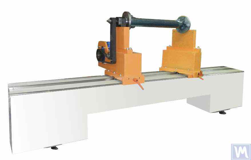
図8.長さ2メートル、重量500キロまでのドライブシャフト用のバランシングマシン
このモデルには2つのスタンドがあり、2つの補正平面でバランスを取ることができる。
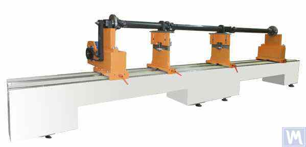
図9.長さ4200mm、重量400kgまでのドライブシャフト用のバランシングマシン
このモデルには4つのスタンドがあり、4つの補正平面で同時にバランスを取ることができる。
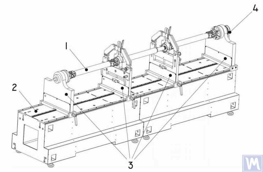
図10.ドライブシャフトの動的バランシングのための水平ハードベアリングバランシングマシン
1 – バランシング対象(ドライブシャフト);2 – 機械ベース;3 – 機械支持部;4 – 機械駆動部;機械支持部の構造要素を図11に示します。
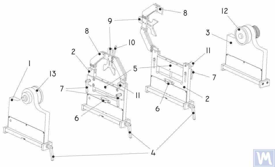
図11.ドライブシャフトの動的バランシングのためのマシンサポート要素
1 - 左非調整式サポート; 2 - 中間調整式サポート(2個); 3 - 右非調整式固定サポート; 4 - サポートフレームロックハンドル; 5 - 可動式サポートプラットフォーム; 6 - サポート垂直調整ナット; 7 - 垂直位置ロックハンドル; 8 - サポートクランプブラケット; 9 - 中間ベアリング可動式クランプ; 10 - クランプロックハンドル; 11 - クランプブラケットロック; 12 - アイテム取り付け用ドライブ(リーディング)スピンドル; 13 - ドライブスピンドル
5.ドライブシャフトのバランシングの準備
以下では、マシンサポートのセットアップと、マシンサポートへのバランスアイテム(4サポートドライブシャフト)の取り付けについて考える。
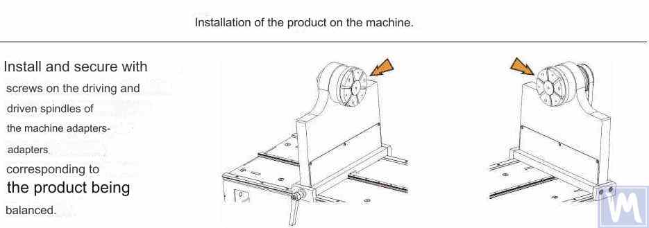
図12.バランシングマシンのスピンドルへの移行フランジの取り付け
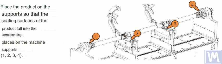
図13 バランシングマシンのサポートへのドライブシャフトの取り付け
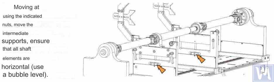
図 14.バランシングマシンのサポート上でバブルレベルを使用してドライブシャフトを水平にする
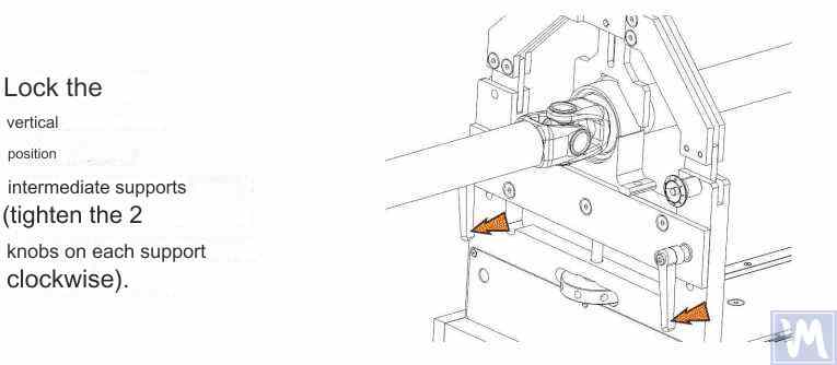
図15.ドライブシャフトの垂直方向の変位を防ぐためにバランシングマシンの中間サポートを固定する。
アイテムを手動で一回転させる。サポートに引っかかることなく、自由に回転することを確認する。この後、機械の機械部分がセットアップされ、アイテムの取り付けが完了する。
6. ドライブシャフトのバランス調整方法:ステップバイステップの手順
どのキットが必要ですか? 2平面で補正を行う2支持マシン(図8)には2チャンネルのBalanset-1Aが必要である。4平面を同時に補正する4支持マシン(図9、および以下の手順)には4チャンネルのBalanset-4Aが必要である。測定と計算のワークフローは同一であり、異なるのはチャンネル数のみである。以下の手順は4平面のセットアップについて説明しているが、ソフトウェアのスクリーンショットは2平面のBalanset-1Aでの同じワークフローを示している—Balanset-4Aでは同じ画面に平面3と平面4が単に追加されるだけである。
バランシングマシンでのドライブシャフトのバランシングプロセスを、Balanset-4A測定システムを例に検討する。Balanset-4Aは、自身のベアリング内で回転しているか、またはバランシングマシンに取り付けられたローターの1、2、3、4の修正平面でのバランシングを目的としたポータブルなバランシングキットである。この装置には、最大4個の振動センサー、位相角センサー、4チャンネル測定ユニット、そしてポータブルコンピュータが含まれる。
補正ウェイトの大きさと位置に関する情報の測定、処理、表示を含むバランシングプロセス全体は自動的に行われ、提供された取扱説明書以上の追加スキルや知識をユーザーに要求しない。すべてのバランシング作業の結果はバランシング・アーカイブに保存され、必要に応じてレポートとして印刷できる。バランシングに加えて、Balanset-4Aは通常の振動タコメーターとしても使用でき、4チャンネルで全振動の実効値(RMS)、振動の回転成分の実効値の測定、およびローター回転周波数の管理が可能である。
さらに、この装置は、振動速度による時間関数と振動スペクトルのグラフを表示することができ、バランス機械の技術的な状態を評価するのに役立ちます。
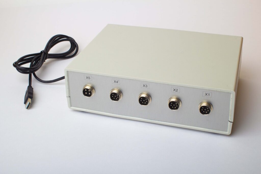
図16。ドライブシャフトバランシングマシンの測定・演算システムとして使用するBalanset-4Aデバイスの外観
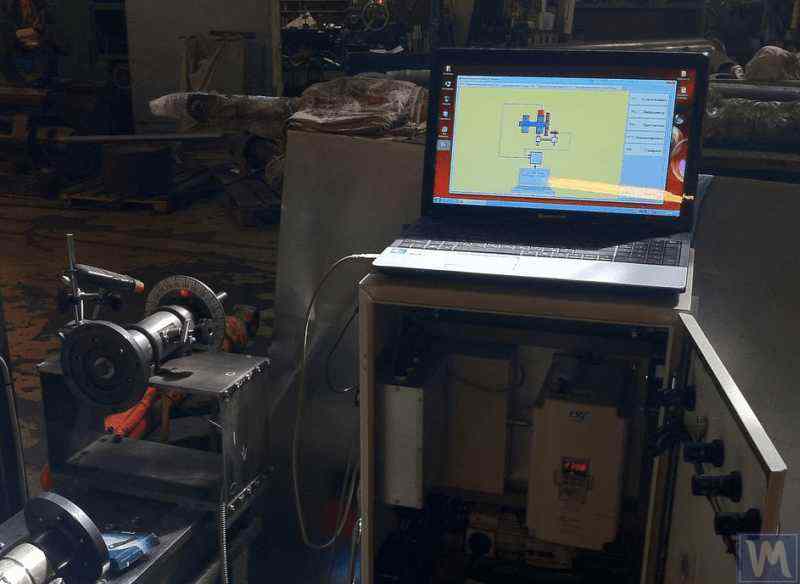
図17。ドライブシャフトバランシングマシンの測定・演算システムとしてBalanset-4Aデバイスを使用する例
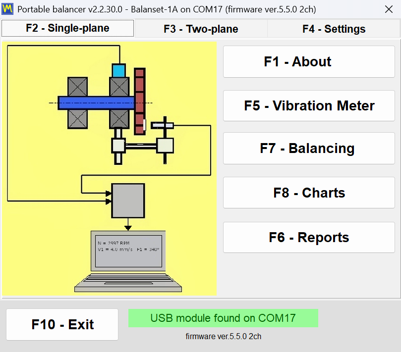
図18. Balansetソフトウェアのメインウィンドウ:F1 - About、F5 - Vibration Meter、F6 - Balancing、F7 - Charts、F8 - Reports
Balanset-4Aデバイスには振動センサーが付属しています。センサーは加速度計方式で、ソフトウェアがその信号を積分し、振動速度をmm/s RMSで表示します。
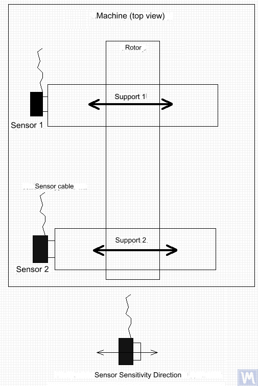
図19。バランシングマシンの支持部へのBalanset-4A振動センサーの取り付け
センサーの感度軸の方向は、支持部の振動変位の方向、この場合は水平方向と一致させる必要があります。センサーの取り付けに関する詳細は、以下を参照してください 動作条件におけるローターのバランス調整.
- バランシングマシンのサポートに振動センサー1、2、3、4を取り付けます。
- 振動センサーをコネクター X1、X2、X3、X4 に接続します。
- 位相角センサー(レーザー・タコメーター)5を、バランス・ローターのラジアル(または端)面とセンサー・ハウジングの間の公称ギャップが10~300mmの範囲になるように取り付けます。
- 少なくとも幅10~15 mmの反射テープマークをローター表面に貼り付ける。
- 位相角センサーをコネクターX5に接続する。
- 測定ユニットをコンピュータのUSBポートに接続します。
- 主電源を使用する場合は、コンピューターを電源ユニットに接続してください。
- 電源装置を220V、50Hzのネットワークに接続する。
- コンピュータの電源を入れ、Balansetソフトウェアを起動してください。
- “F6 - Balancing”ボタンでバランシングのワークスペースを開き、“Plane count”フィールドに必要な修正面の数を設定します。これにより、測定ユニットの入力に接続された振動センサーで、振動が同時に測定されます。
- センサーと測定ユニットの接続を示す模式図が、図18に示すようにコンピュータの画面に表示されます。
バランシングを行う前に、振動計モード(F5ボタン)で測定を行うことをお勧めします。
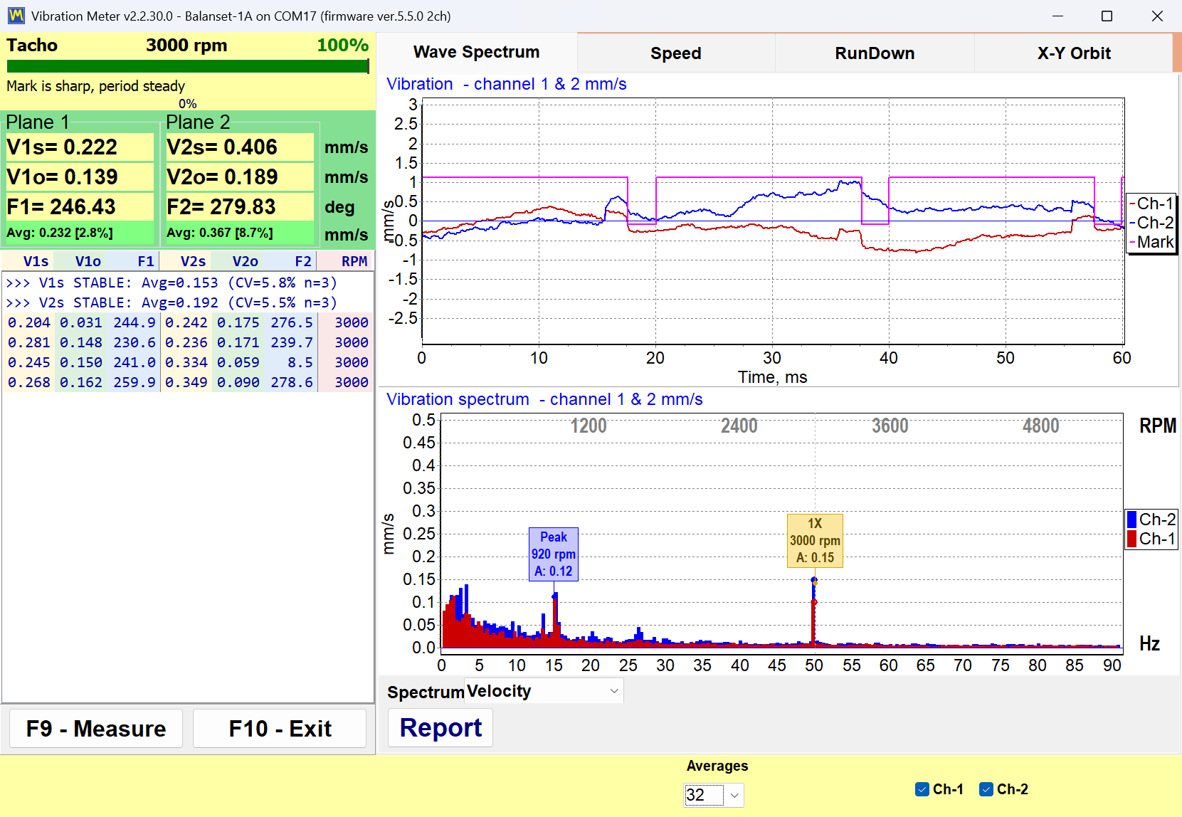
図20。Vibration Meterモード(F5):総合振動V1s、V2s、および回転成分V1o、V2o(位相F1、F2)を、mm/s RMSの振動速度として表示
振動の総振幅V1s(V2s)が回転成分の振幅V1o(V2o)とほぼ一致する場合、機構の振動の主な要因はローターのアンバランスであると推定できます。振動の総振幅V1s(V2s)が回転成分V1o(V2o)を大幅に上回る場合は、機構の点検をお勧めします。具体的には、ベアリングの状態を確認し、基礎への確実な取り付け、回転中にローターが固定部品に接触しないことを確認し、他の機構からの振動の影響を考慮することなどが挙げられます。
ここでは、チャートモード(“F7 - Charts”、“F5-Spectrum (Hz)”タブ)で時間関数のグラフや振動スペクトルを調べると役立つことがあります。
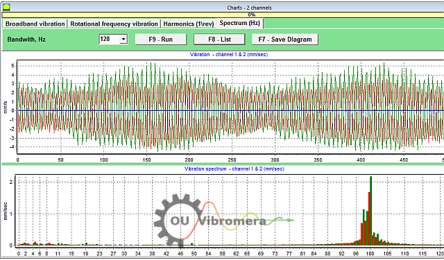
図21.振動の時間関数とスペクトルのグラフ
グラフは、振動レベルが最も高い周波数を示しています。これらの周波数がバランス機構のローターの回転周波数と異なる場合は、バランス調整前にこれらの振動成分の発生源を特定し、それらを除去する対策を講じる必要があります。
ドライブシャフトのスペクトルの読み方:1xはアンバランス、2xはジョイント自体である可能性があります。 回転周波数(1x)における支配的なピークはアンバランスを示す—これがバランシングによって除去されるものである。回転周波数の2倍(2x)における支配的なピーク、特に強い軸方向振動を伴う場合は、ジョイント角度、摩耗したクロスやスプライン、あるいは ずれ:角度γで作動するユニバーサル(カルダン)ジョイントでは、従動側のヨークが1回転につき2回、進みと遅れを繰り返すため、シャフトが完全にバランスされていても2x成分が生じます。バランシングではこれを除去できません。ジョイント角を等しくし(γ1 = γ2)、先にジョイントを点検してください。チャートモード(“F7 - Charts”)では、“F5-Spectrum (Hz)”タブにスペクトルが、“F3-1x vibration”タブに回転成分が表示されます。3000 min-1 1x = 50 Hz、2x = 100 Hz。
また、振動計モードでの測定値の安定性にも注意を払うことが重要です。測定中に振動の振幅と位相が 10-15% 以上変化してはなりません。そうでなければ、機構が共振領域付近で動作している可能性があります。この場合、ローター速度を調整する必要があります。
新しいローターの4平面バランシングを行う場合、5回のキャリブレーション運転と、少なくとも1回のトリム運転(Run T)がバランス調整済みのマシンに対して必要である。テストウェイトなしの最初のマシン運転時の振動測定は、バランシング作業画面でRun 0として実行される。以降の運転はテストウェイトを付けて行われ、各修正平面(各バランシングマシン支持部の付近)に順次ドライブシャフト上へ取り付けられる。
その後の各運転の前に、以下のステップを踏むべきである:
- バランスをとった機械のローターの回転を停止します。
- 先に取り付けた試走用ウェイトを取り外します。
- トライアルウェイトを次の平面に取り付ける。
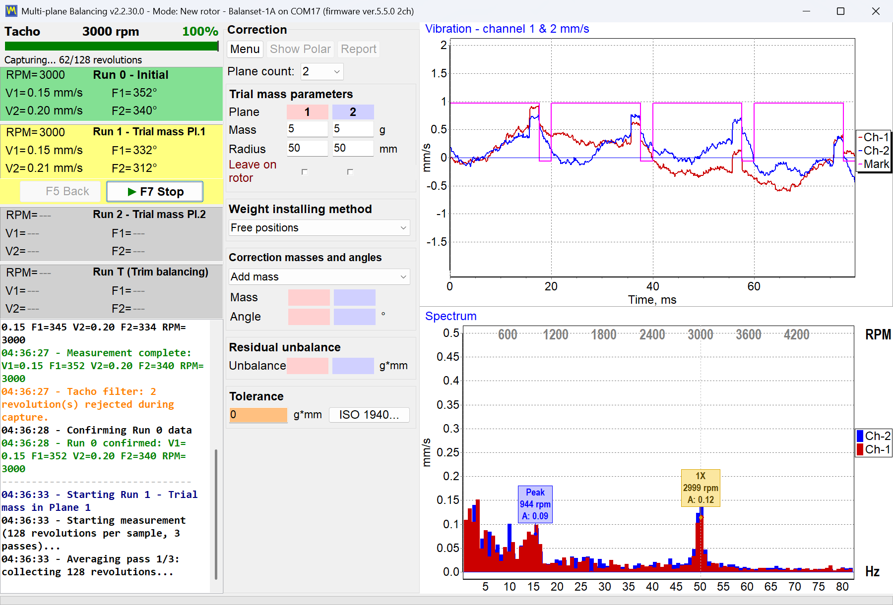
図22. 測定運転中のバランシングのワークスペース(“F6 - Balancing”):Run 0 - Initial、試し錘の運転Run 1とRun 2、およびトリム運転Run T
各測定を完了した後、ローターの回転周波数(Nオブ)、および実効値(Vo1, Vo2, Vo3, Vo4)と位相(F1, F2, F3, F4) のバランス対象ローターの回転周波数における振動が、プログラムウィンドウの対応するフィールドに保存されます。5回目の運転(Weight in Plane 4)の後、極座標プロット付きのバランシング結果(図23参照)が表示され、質量の計算値(M1, M2, M3, M4)と設置角度(f1, f2, f3, f4)のアンバランスを補正するために、4つの平面でローターに設置する必要がある補正ウェイト。
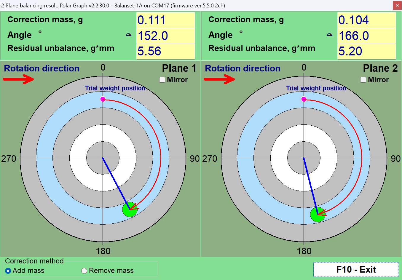
図23。バランシング結果の極座標図:各平面の計算された補正質量と角度を、試しおもりの位置から回転方向に測って示す
注意! バランス調整機の5回目の運転中に測定プロセスを完了したら、ローターの回転を停止し、以前に取り付けた試験用ウェイトを取り外します。この操作を行った後にのみ、ローターへの補正用ウェイトの取り付け(または取り外し)を進めることができます。
極座標系におけるローターへの補正用ウェイトの追加(または削除)角度位置は、試験用ウェイトの設置位置から測定されます。角度測定方向はローターの回転方向と一致します。ブレードによるバランス調整の場合、バランス調整されたローターのブレード(条件付きで1番目とみなされる)は、試験用ウェイトの設置位置と一致します。コンピュータ画面に表示されるブレードの番号方向は、ローターの回転方向に従います。
このバージョンのプログラムでは、補正ウェイトはローターに追加されることがデフォルトで想定されている。これは「Add mass」フィールドに設定されたマークで示される。ウェイトを取り除くことでアンバランスを補正する必要がある場合(例えば穴あけによる場合)は、マウスを使って「Remove mass」フィールドにマークを設定する。その後、補正ウェイトの角度位置は自動的に180度変更される。
バランス対象ローターに補正ウェイトを取り付けた後、トリム運転(Run T)を実行してバランシング作業の有効性を確認する。トリム運転完了後、ローターの回転周波数(Nオブ)と実効値(Vo1, Vo2, Vo3, Vo4)と位相(F1, F2, F3, F4) バランス対象ローターの回転周波数における振動が保存されます。同時に、バランシング結果(図23参照)が更新され、残留アンバランスを補償するためにローターに取り付ける(または取り外す)必要がある追加の補正ウェイトの計算パラメータが表示されます。さらに、このワークスペースには、バランシング後に達成された残留アンバランスの値も表示されます。バランス対象ローターの残留振動および/または残留アンバランスの値が技術文書に規定された許容範囲を満たしていれば、バランシングプロセスを完了できます。満たしていなければ、バランシングプロセスを継続できます。この方法により、バランス対象ローターへの補正ウェイトの取り付け(取り外し)時に生じ得る誤差を、逐次近似によって修正することができます。
バランシングプロセスを継続する場合は、バランシング結果に表示された計算パラメータに従って、バランス調整済みのロータに追加の補正おもりを取り付ける(または取り外す)必要があります。
5回のキャリブレーション運転の結果から計算されたローターバランシング係数(動的影響係数)は、コンピュータのメモリに保存され、同じタイプのローターをバランシングする際に「Load Coefficients」機能で再利用できる。
7.リジッドローターの推奨バランシング精度クラス
以下のグレードは、ISO 1940-1のバランス品質グレードGであり、数値を変更せずにISO 21940-11:2016に引き継がれています。グレードはG = eとして定義されper·Ω、ここでeper は許容比残留アンバランス(g·mm/kg = µm)であり、Ω = 2πn/60は使用角速度(rad/s)です。許容残留アンバランスは次のようにUとして求められますper = 9549·G·M/n [g·mm]、これを補正平面間で分割します。詳しくは弊社の ISO 1940-1 用語集記事をご覧ください。
路上走行車のドライブシャフトのデフォルトグレードはG 40であり、図面またはOEM仕様で特殊要件が求められる場合はG 16が適用される。残留アンバランスと振動は別個の合格基準であることに注意すること—組み立てられた機械の振動はISO 20816(旧ISO 10816)に基づいて評価される—詳しくは弊社の ISO 10816-1 用語集記事をご覧ください。
Gグレード表は剛性ローターにのみ適用される—すなわち、使用速度が第一曲げ危険速度のおよそ0.5~0.7倍を下回るローターである。長いドライブシャフト(2m以上、および中間支持を持つあらゆるシャフト)はこの限界に近づく可能性がある。シャフトの第一危険速度を、使用速度とバランシング速度の両方と照合すること。シャフトが運転速度でフレキシブルである場合は、モーダル法/多速度手順(ISO 21940-12)を使用すること—2平面の剛性ローター補正では対応できない。
表 2.リジッドローターの推奨バランシング精度クラス。

| 機械の種類(ローター) | バランシング精度クラス | バランス品質等級 G = eper·Ω, mm/s |
|---|---|---|
| 大型舶用低速ディーゼルエンジン(ピストン速度9m/s以下)用の駆動クランクシャフト(構造的にアンバランスなもの) | G 4000 | 4000 |
| 大型舶用低速ディーゼルエンジン(ピストン速度9m/s以下)用ドライブクランクシャフト(構造バランス型) | G 1600 | 1600 |
| 防振装置上の駆動クランクシャフト(構造的にアンバランス) | G 630 | 630 |
| リジッドサポート上の駆動クランクシャフト(構造的にアンバランス) | G 250 | 250 |
| 乗用車、トラック、機関車用に組み立てられた往復動エンジン | G 100 | 100 |
| 防振台上の駆動クランクシャフト(構造的にバランスされている) | G 40 | 40 |
| 自動車のホイール、ホイールリム、輪軸、ドライブシャフト(カルダンシャフト) | G 40 | 40 |
| 農業機械 | G 16 | 16 |
| リジッドサポート上の駆動クランクシャフト(バランス型) | G 16 | 16 |
| 粉砕機 | G 16 | 16 |
| 特別な要求事項を伴うドライブシャフト(プロペラシャフト/カルダンシャフト) | G 16 | 16 |
| 航空機用ガスタービン | G 6.3 | 6.3 |
| 遠心分離機(セパレーター、セトラー) | G 6.3 | 6.3 |
| 最大公称回転速度が毎分950回転までの電動機および発電機(シャフトの高さが80mm以上)。-1 | G 6.3 | 6.3 |
| シャフトの高さが80mm以下の電気モーター | G 6.3 | 6.3 |
| ファン | G 6.3 | 6.3 |
| ギアドライブ | G 6.3 | 6.3 |
| 汎用機 | G 6.3 | 6.3 |
| 金属切削機械 | G 6.3 | 6.3 |
| 製紙機械 | G 6.3 | 6.3 |
| ポンプ | G 6.3 | 6.3 |
| ターボチャージャー | G 6.3 | 6.3 |
| 水車 | G 6.3 | 6.3 |
| コンプレッサー | G 6.3 | 6.3 |
| コンピュータ制御ドライブ | G 2.5 | 2.5 |
| 最大公称回転速度が950 minを超える電動機および発電機(シャフトの高さが80 mm以上のもの-1 | G 2.5 | 2.5 |
| ガスタービンおよび蒸気タービン | G 2.5 | 2.5 |
| 金属切削機械のドライブ | G 2.5 | 2.5 |
| 繊維機械 | G 2.5 | 2.5 |
| オーディオ・ビデオ機器のドライブ | G 1 | 1 |
| 研削盤ドライブ | G 1 | 1 |
| 高精度機器のスピンドルとドライブ | G 0.4 | 0.4 |
ドライブシャフトのバランス調整に関するよくある質問
ドライブシャフトバランシングとは何ですか?
ドライブシャフトのバランス調整は、ドライブシャフトの質量アンバランスを修正し、振動を起こさずにスムーズに回転するようにするプロセスです。このプロセスでは、シャフトの片側が重くなっている部分を測定し、そのアンバランスを解消するために少量の重量を追加または削減(例えば、バランスウェイトの溶接)します。バランスの取れたドライブシャフトは均等に回転するため、過度の振動や車両部品の摩耗を防ぎます。
ドライブシャフトのバランス調整が重要なのはなぜですか?
ドライブシャフトのバランスが崩れると、特に特定の速度域で強い振動が発生し、加速時やギアシフト時にガタガタとした異音が発生することがあります。こうした振動は、時間の経過とともにベアリング、ユニバーサルジョイント、その他のドライブトレイン部品に損傷を与える可能性があります。ドライブシャフトのバランス調整を行うことで、こうした振動が解消され、スムーズな乗り心地が確保され、部品への負担が軽減され、高額な損傷やダウンタイムを防ぐことができます。
ドライブシャフトのバランスが崩れた場合の一般的な症状は何ですか?
ドライブシャフトのバランスが崩れたり故障したりすると、一般的には、特に速度が上昇すると、車体の床やシートに顕著な振動や震えが感じられることがあります。また、ギアチェンジ時や加減速時に、ノッキング音やガタガタ音が聞こえることもあります。場合によっては、アンバランスによりユニバーサルジョイントが過熱することもあります。これらの兆候が見られる場合は、ドライブシャフトのバランス調整または修理が必要になる可能性があります。
ドライブシャフトのバランスはどうやって取るのでしょうか?
ドライブシャフトのバランシングは通常、専用のバランシングマシンを使用して行われる。ドライブシャフトを取り付けて高速で回転させ、センサーがアンバランスを検出する。技術者は、マシンの読み取り値に基づいて、特定の位置にドライブシャフトへ小さなウェイトを取り付ける(または材料を除去する)。この工程は、ドライブシャフトが目立った振動なしに回転するようになるまで繰り返される。Balanset-4Aのような最新のシステムは、この工程を案内し、正確なバランシングのためにどこにどれだけの重量を追加すべきかを計算することができる。
結論
結論として、安全性、パフォーマンス、コスト削減には、適切なドライブシャフトのバランス調整が不可欠です。 アンバランスを検出し修正することで、部品の不要な摩耗を防ぎ、故障による損傷を回避し、機械の最適な性能を維持することができる。Balanset-1AやBalanset-4Aのような最新のバランシングシステムは、この工程を効率化し、小規模な工房でもプロフェッショナルな結果を達成できるようにする。
ドライブシャフトの振動が持続する場合や、信頼性の高いバランス調整ソリューションが必要な場合は、迷わずに行動を起こしてください。このガイドに記載されている手順を実行するか、当社の専門家にご相談ください。適切なアプローチと機器を使用することで、ドライブシャフトが今後何年もスムーズかつ確実に動作することを保証できます。 お問い合わせ 詳細を知りたい場合や、ニーズに最適なドライブ シャフト バランシング装置を探している場合は、こちらをご覧ください。








Nikolai Shelkovenko
Nikolai Shelkovenkoは、振動解析エンジニアであり、Vibromeraの創業者兼CEOです。 15年以上にわたり、彼は試験台上ではなく現場で回転機械のバランシングを行ってきました——マルチャー、産業用ファン、クラッシャー、遠心分離機、シャフト、スピンドルなど。この経験から生まれたのがBalanset計測器であり、専門家が機械のもとへ持ち運び、現場で単独で使用できる道具として設計されています。実験室用の機器ではありません。 Vibromeraは2017年に設立され、2023年以降はポルトガル・ポルトを拠点としています。Balansetシリーズの開発、組み立て、サポートはすべてここで行われています。フラッグシップ機器はBalanset-1Aであり、単一平面および二平面バランシングと振動診断のための可搬式アナライザーです。 Nikolaiは、カスタマーサポート、困難なバランシング案件への対応、そしてソフトウェアの開発に自ら携わっています。世界中の顧客と、どの言語でも対応しています。


0コメント