موازنة عمود الدفع: دليل شامل
أجهزة الموازنة الديناميكية لأعمدة الدفع ونظام قياس لآلات الموازنة Balanset-4 – 6,803 يورو
تخيل أنك تقود شاحنة وفجأة تشعر باهتزاز قوي أو تسمع صوت طقطقة مرتفع عند التسارع أو تغيير التروس. هذا أكثر من مجرد إزعاج، بل قد يكون علامة على اختلال توازن عمود الدفع. بالنسبة للمهندسين والفنيين، تشير هذه الاهتزازات والضوضاء إلى انخفاض الكفاءة، وتآكل متسارع للمكونات، وتوقف محتمل ومكلف إذا تُرك دون علاج.
في هذا الدليل الشامل، نقدم حلولاً عملية لمشاكل توازن عمود الدفع. ستتعلم ما هو عمود الدفع ولماذا يحتاج إلى الموازنة، وتتعرف على الأعطال الشائعة التي تسبب الاهتزاز أو الضوضاء، وتتبع عملية واضحة خطوة بخطوة لموازنة عمود الدفع الديناميكي. بتطبيق هذه الممارسات الفضلى، يمكنك توفير المال على الإصلاحات، وتقليل وقت استكشاف الأخطاء وإصلاحها، وضمان تشغيل آلاتك أو مركبتك بكفاءة مع أقل قدر من الاهتزاز.
Table of Contents
- 1. Types of Driveshafts
- 2. Universal Joint Drive Malfunctions
- 3. Driveshaft Balancing
- 4. Modern Balancing Machines for Driveshafts
- 5. Preparation for Driveshaft Balancing
- 6. Driveshaft Balancing Procedure
- 7. Recommended Balancing Accuracy Classes for Rigid Rotors


1. Types of Driveshafts
A universal joint drive (driveshaft) is a mechanism that transmits torque between shafts that intersect at the center of the universal joint and can move relative to each other at an angle. In a vehicle, the driveshaft transmits torque from the gearbox (or transfer case) to the driven axles in the case of a classical or all-wheel-drive configuration. For all-wheel-drive vehicles, the universal joint usually connects the driven shaft of the gearbox to the drive shaft of the transfer case, and the driven shafts of the transfer case to the drive shafts of the main drives of the driven axles.
يمكن للوحدات المُثبّتة على الهيكل (مثل علبة التروس وعلبة النقل) أن تتحرك بالنسبة لبعضها البعض بسبب تشوه دعائمها والهيكل نفسه. في الوقت نفسه، تُثبّت محاور الدفع بالهيكل عبر نظام التعليق، ويمكنها أن تتحرك بالنسبة للهيكل والوحدات المُثبّتة عليه بسبب تشوه عناصر التعليق المرنة. لا تُغيّر هذه الحركة زوايا أعمدة الدفع التي تربط الوحدات فحسب، بل تُغيّر أيضًا المسافة بينها.
The universal joint drive has a significant disadvantage: the non-uniform rotation of the shafts. If one shaft rotates uniformly, the other does not, and this non-uniformity increases with the angle between the shafts. This limitation prevents the use of a universal joint drive in many applications, such as in the transmission of front-wheel-drive vehicles, where the main issue is transmitting torque to the turning wheels. This disadvantage can be partially compensated by using double universal joints on one shaft, which are turned a quarter of a turn relative to each other. However, in applications requiring uniform rotation, constant velocity joints (CV joints) are typically used instead. CV joints are a more advanced but also more complex design serving the same purpose.
Universal joint drives can consist of one or more universal joints connected by driveshafts and intermediate supports.
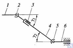
Figure 1. Diagram of a universal joint drive: 1, 4, 6 — driveshafts; 2, 5 — universal joints; 3 — compensating connection; u1, u2 — angles between shafts
بشكل عام، يتكون محرك المفصل العالمي من المفصلين العالميين 2 و5، وأعمدة الدفع 1 و4 و6، ووصلة تعويضية 3. في بعض الأحيان، يُركّب عمود الدفع على دعامة وسيطة متصلة بالعارضة المتقاطعة لإطار السيارة. تضمن المفاصل العالمية نقل عزم الدوران بين الأعمدة التي تتقاطع محاورها بزاوية. تُقسّم المفاصل العالمية إلى أنواع غير منتظمة السرعة وثابتة السرعة. كما تُصنّف المفاصل غير المنتظمة السرعة إلى أنواع مرنة وصلبة. يمكن أن تكون مفاصل السرعة الثابتة كروية ذات أخاديد فاصلة، أو كروية ذات ذراع فاصل، أو كامة. تُركّب عادةً في محرك العجلات الأمامية المتحكم بها، حيث يمكن أن تصل الزاوية بين الأعمدة إلى 45 درجة، ويجب أن يتطابق مركز المفصل العالمي مع نقطة تقاطع محاور دوران العجلة ومحور دورانها.
تنقل الوصلات العامة المرنة عزم الدوران بين أعمدة ذات محاور متقاطعة بزاوية تتراوح بين 2 و3 درجات، وذلك بفضل التشوه المرن لعناصر التوصيل. أما الوصلة الصلبة غير المنتظمة السرعة، فتنقل عزم الدوران من عمود إلى آخر عبر وصلة متحركة لأجزاء صلبة. تتكون من نيرين - 3 و5 - مثبتين في فتحات أسطوانية تُثبت فيها أطراف عنصر التوصيل - الصليب 4 - A وB وV وG - على محامل. يتصل النيران بشكل صارم بالعمودين 1 و2. يدور النير 5 حول المحور BG للصليب، وفي الوقت نفسه، مع الصليب، حول المحور AV، مما يسمح بنقل الدوران من عمود إلى آخر بزاوية متغيرة بينهما.
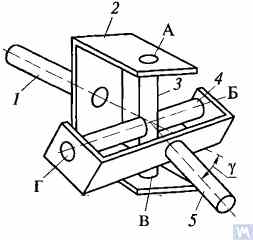
Figure 2. Diagram of a rigid non-uniform velocity universal joint
If shaft 7 rotates around its axis by an angle α, then shaft 2 will rotate by an angle β over the same period. The relationship between the rotation angles of shafts 7 and 2 is determined by the expression tanα = tanβ * cosγحيث γ هي الزاوية التي تقع عندها محاور الأعمدة. يشير هذا التعبير إلى أن الزاوية β تكون أحيانًا أقل أو مساوية أو أكبر من الزاوية α. وتحدث تساوي هذه الزوايا كل 90 درجة من دوران العمود 7. لذلك، مع الدوران المنتظم للعمود 1، تكون السرعة الزاوية للعمود 2 غير منتظمة وتتغير وفقًا لقانون جيبي. ويزداد عدم انتظام دوران العمود 2 بازدياد الزاوية γ بين محاور الأعمدة.
If the non-uniform rotation of shaft 2 is transmitted to the shafts of the units, additional pulsating loads will occur in the transmission, increasing with the angle γ. To prevent the non-uniform rotation of shaft 2 from being transmitted to the unit shafts, two universal joints are used in the universal joint drive. They are installed so that the angles γ1 and γ2 are equal; the forks of the universal joints, fixed on the non-uniformly rotating shaft 4, should be positioned in the same plane.
يوضح الشكل 3 تصميم الأجزاء الرئيسية لمحركات المفصل العالمي. يتكون المفصل العالمي غير المنتظم السرعة من نيرين (1) متصلين بصليب (3). يحتوي أحد النيرين أحيانًا على شفة، بينما يكون الآخر ملحومًا بأنبوب عمود الدفع أو يحتوي على طرف مسنن (6) (أو غلاف) للتوصيل بعمود الدفع. يتم تثبيت محاور الصليب في عيون كلا النير على محامل الإبرة (7). يوجد كل محمل في علبة (2) ويتم تثبيته في عين النير بغطاء، متصل بالنير بمسامير مثبتة بألسنة على الغسالة. في بعض الحالات، يتم تأمين المحامل في النير بحلقات سريعة. للحفاظ على التزييت في المحمل وحمايته من الماء والأوساخ، يوجد ختم مطاطي ذاتي الشد. يتم ملء التجويف الداخلي للصليب بالشحم من خلال وصلة شحم تصل إلى المحامل. عادةً ما يكون للصليب صمام أمان لحماية الختم من التلف الناتج عن ضغط الشحم المُضخّ فيه. يُزيّت الوصلة المُسننة (6) باستخدام وصلة الشحم (5).
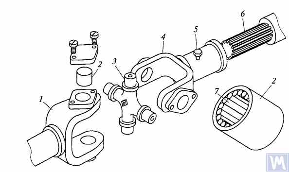
Figure 3. Details of a rigid non-uniform velocity universal joint
عادةً لا تتجاوز الزاوية القصوى بين محاور الأعمدة المتصلة بمفاصل عالمية صلبة غير منتظمة السرعة 20 درجة، حيث تنخفض الكفاءة بشكل ملحوظ عند زوايا أكبر. إذا تفاوتت الزاوية بين محاور الأعمدة في حدود 0...2%، فإن محاور الوصلة المتقاطعة تتشوه بفعل محامل الإبرة، مما يؤدي إلى تلف المفصل العالمي بسرعة.
في عمليات نقل الحركة للمركبات المجنزرة عالية السرعة، غالبًا ما يتم استخدام الوصلات العالمية مع أنواع اقتران التروس، والتي تسمح بنقل عزم الدوران بين الأعمدة ذات المحاور المتقاطعة بزوايا تصل إلى 1.5...2 درجة.
Driveshafts are typically made tubular, using special steel seamless or welded tubes. The yokes of the universal joints, splined sleeves, or tips are welded to the tubes. To reduce the transverse loads acting on the driveshaft, dynamic balancing is performed with the universal joints assembled. Imbalance is corrected by welding balancing plates to the driveshaft or sometimes by installing balancing plates under the bearing caps of the universal joints. The relative position of the splined connection parts after assembly and balancing of the universal joint drive at the factory is usually marked with special labels.
The compensating connection of the universal joint drive is usually made in the form of a splined connection, allowing axial movement of the universal joint drive parts. It consists of a splined tip that fits into the splined sleeve of the universal joint drive. Lubrication is introduced into the splined connection through a grease fitting or applied during assembly and replaced after prolonged use of the vehicle. A seal and a cover are typically installed to prevent grease leakage and contamination.
For long driveshafts, intermediate supports are usually used in universal joint drives. An intermediate support typically consists of a bracket bolted to the vehicle frame cross member, in which a ball bearing is mounted in a rubber elastic ring. The bearing is sealed on both sides with caps and has a lubrication device. The elastic rubber ring helps to compensate for assembly inaccuracies and bearing misalignment that may occur due to frame deformations.
A universal joint with needle bearings (Figure 4a) consists of yokes, a cross, needle bearings, and seals. The cups with needle bearings are fitted onto the trunnions of the cross and sealed with seals. The cups are secured in the yokes with snap rings or caps fastened with screws. Universal joints are lubricated through a grease fitting via internal drillings in the cross. A safety valve is used to eliminate excess oil pressure in the joint. During uniform rotation of the driving yoke, the driven yoke rotates non-uniformly: it advances and lags behind the driving yoke twice per revolution. To eliminate non-uniform rotation and reduce inertial loads, two universal joints are used.
In the drive to the front driving wheels, constant velocity universal joints are installed. The constant velocity joint drive of GAZ-66 and ZIL-131 vehicles consists of yokes 2, 5 (Figure 4b), four balls 7, and a central ball 8. The driving yoke 2 is integral with the inner axle shaft, while the driven yoke is forged together with the outer axle shaft, at the end of which the wheel hub is fixed. The driving moment from yoke 2 to yoke 5 is transmitted through balls 7, which move along circular grooves in the yokes. The central ball 8 serves to center the yokes and is held in place by studs 3, 4. The rotation frequency of yokes 2, 5 is the same due to the symmetry of the mechanism relative to the yokes. The change in shaft length is ensured by the free splined connections of the yokes with the shaft.
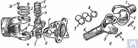
Figure 4. Universal Joints: a — universal joint: 1 — cap; 2 — cup; 3 — needle bearing; 4 — seal; 5, 9 — yokes; 6 — safety valve; 7 — cross; 8 — grease fitting; 10 — screw; b — constant velocity universal joint: 1 — inner axle shaft; 2 — driving yoke; 3, 4 — studs; 5 — driven yoke; 6 — outer axle shaft; 7 — balls; 8 — central ball
2. Universal Joint Drive Malfunctions
Universal joint drive malfunctions typically manifest as sharp knocks in the universal joints that occur when the vehicle is moving, especially during shifts between gears and sudden increases in the engine crankshaft speed (for example, when transitioning from engine braking to acceleration). A sign of universal joint malfunction can be its heating to a high temperature (over 100°C). This happens due to significant wear of the bushings and trunnions of the universal joint, needle bearings, crosses, and splined connections, resulting in misalignment of the universal joint and significant impact axial loads on the needle bearings. Damage to the cork seals of the universal joint cross leads to rapid wear of the trunnion and its bearing.
During maintenance, the universal joint drive is checked by sharply rotating the driveshaft by hand in both directions. The degree of free rotation of the shaft determines the wear of the universal joints and splined connections. Every 8-10 thousand kilometers, the condition of the bolted connections of the driven shaft flanges of the gearbox and the drive shaft of the main transmission gear with the flanges of the end universal joints and the fastening of the intermediate support of the driveshaft are checked. The condition of the rubber boots on the splined connections and the cork seals of the universal joint cross is also checked. All fastening bolts must be tightened fully (tightening torque 8-10 kgf·m).
Needle bearings of the universal joints are lubricated with liquid oil used for transmission units; splined connections in most vehicles are lubricated with greases (US-1, US-2, 1-13, etc.); the use of grease for lubricating needle bearings is strictly prohibited. In some vehicles, splined connections are lubricated with transmission oil. The intermediate support bearing, mounted in a rubber sleeve, practically does not require lubrication, as it is lubricated during assembly at the factory. The support bearing of the ZIL-130 vehicle is lubricated with grease through a pressure fitting during regular maintenance (every 1100-1700 km).
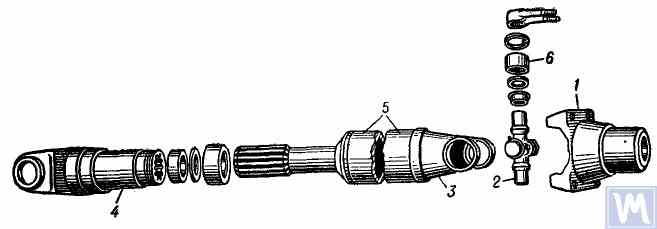
Figure 5. Universal joint drive: 1 — flange for securing the driveshaft; 2 — universal joint cross; 3 — universal joint yoke; 4 — sliding yoke; 5 — driveshaft tube; 6 — needle roller bearing with closed end
The universal joint drive consists of two universal joints with needle bearings, connected by a hollow shaft, and a sliding yoke with involute splines. To ensure reliable protection from dirt and provide good lubrication of the splined connection, the sliding yoke (6), connected to the secondary shaft (2) of the gearbox, is placed in an extension (1) attached to the gearbox housing. Additionally, this location of the splined connection (outside the zone between the joints) significantly increases the stiffness of the universal joint drive and reduces the likelihood of shaft vibrations when the sliding splined connection wears out.
عمود الدفع مصنوع من أنبوب رفيع الجدار ملحوم كهربائيًا (8)، يُثبَّت فيه نيرتان متطابقتان (9) بالضغط من كل طرف، ثم يُلحمان بالقوس الكهربائي. تُثبَّت أغلفة محامل الإبر (18) للصليب (25) بالضغط في عيون النير (9)، وتُثبَّت بحلقات تثبيت زنبركية (20). يحتوي كل محمل وصلة عامة على 22 إبرة (21). تُثبَّت أغطية مختومة (24) بالضغط على محاور الصلبان البارزة، حيث تُثبَّت حلقات الفلين (23). تُشحَّن المحامل باستخدام وصلة شحم زاوية (17) تُثبَّت في فتحة ملولبة في وسط الصليب، متصلة بقنوات مرورية في محاور الصليب. على الجانب الآخر من وصلة المفصل العالمي، يوجد صمام أمان (16) في مركزها، مصمم لتصريف الشحم الزائد عند ملء الوصلة والمحامل، ولمنع تراكم الضغط داخل الوصلة أثناء التشغيل (يُفعّل الصمام عند ضغط حوالي 3.5 كجم/سم²). ترجع ضرورة تركيب صمام أمان إلى أن زيادة الضغط المفرطة داخل الوصلة قد تؤدي إلى تلف (انبثاق) أختام الفلين.
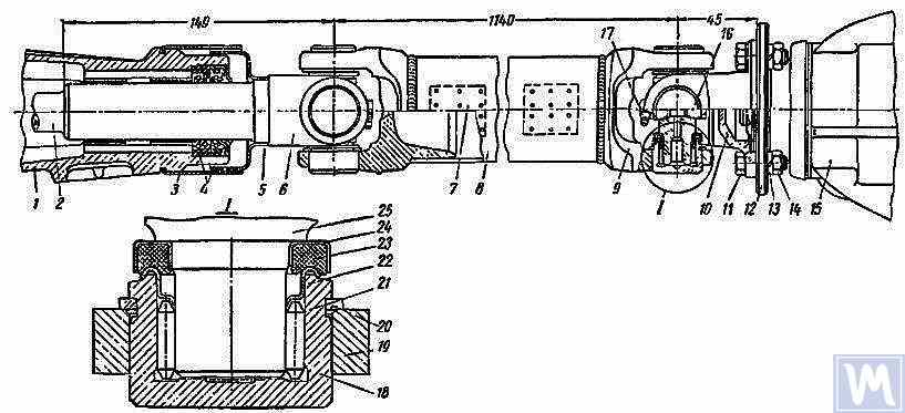
Figure 6. Driveshaft Assembly: 1 — gearbox extension; 2 — secondary shaft of the gearbox; 3 and 5 — dirt deflectors; 4 — rubber seals; 6 — sliding yoke; 7 — balancing plate; 8 — driveshaft tube; 9 — yoke; 10 — flange yoke; 11 — bolt; 12 — flange of the rear axle drive gear; 13 — spring washer; 14 — nut; 15 — rear axle; 16 — safety valve; 17 — angular grease fitting; 18 — needle bearing; 19 — yoke eye; 20 — spring retaining ring; 21 — needle; 22 — washer with toroidal end; 23 — cork ring; 24 — stamped cap; 25 — cross
عمود الدفع، المُجمّع بمفصلين عالميين، مُوازن ديناميكيًا بعناية من كلا الطرفين عن طريق لحام ألواح الموازنة (7) بالأنبوب. لذلك، عند تفكيك العمود، يجب وضع علامات دقيقة على جميع أجزائه لإعادة تجميعها في مواضعها الأصلية. يؤدي عدم اتباع هذه التعليمات إلى اختلال توازن العمود، مما يُسبب اهتزازات قد تُلحق الضرر بناقل الحركة وهيكل السيارة. في حال تآكل بعض الأجزاء، خاصةً إذا انثنى الأنبوب بسبب الاصطدام، واستحالة موازنة العمود ديناميكيًا بعد التجميع، يجب استبدال العمود بأكمله.
Possible Driveshaft Malfunctions, Their Causes, and Solutions
| Cause of Malfunction | Solution |
|---|---|
| Driveshaft Vibration | |
| 1. Shaft bending due to an obstacle | 1. Straighten and dynamically balance the assembled shaft or replace the assembled shaft |
| 2. Bearing and cross wear | 2. Replace bearings and crosses and dynamically balance the assembled shaft |
| 3. Wear of extension bushings and sliding yoke | 3. Replace the extension and sliding yoke and dynamically balance the assembled shaft |
| Knocks When Starting and Coasting | |
| 1. Wear of sliding yoke splines or secondary gearbox shaft | 1. Replace worn parts. When replacing the sliding yoke, dynamically balance the assembled shaft |
| 2. Loose bolts securing the flange yoke to the rear axle drive gear flange | 2. Tighten bolts |
| Oil Throwing from Universal Joint Seals | |
| Wear of cork rings in universal joint seals | Replace cork rings, maintaining the relative position of all driveshaft parts during reassembly. If there is wear on crosses and bearings, replace the bearings and crosses and dynamically balance the assembled shaft |
3. Driveshaft Balancing
After repairing and assembling the driveshaft, it is dynamically balanced on a machine. One design of a balancing machine is shown in Figure 7. The machine consists of a plate (18), a pendulum frame (8) mounted on four vertical elastic rods (3), ensuring its oscillation in the horizontal plane. A bracket and front headstock (9), secured on a bracket (4), are mounted on the longitudinal tubes of the pendulum frame (8). The rear headstock (6) is on a movable traverse (5), allowing dynamic balancing of driveshafts of different lengths. The headstock spindles are mounted on precision ball bearings. The spindle of the front headstock (9) is driven by an electric motor installed in the machine base, through a V-belt drive and an intermediate shaft, on which a limb (10) (graduated disk) is mounted. Additionally, two stands (15) with retractable locking pins (17) are installed on the machine plate (18), ensuring the fixation of the front and rear ends of the pendulum frame depending on the balancing of the front or rear end of the driveshaft.
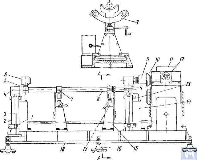
Figure 7. Dynamic Balancing Machine for Driveshafts
1—clamp; 2—dampers; 3—elastic rod; 4—bracket; 5—movable traverse; 6—rear headstock; 7—crossbar; 8—pendulum frame; 9—front driving headstock; 10—limb-disk; 11—millivoltmeter; 12—limb of the commutator-rectifier shaft; 13—magnetoelectric sensor; 14—fixed stand; 15—fixator stand; 16—support; 17—fixator; 18—support plate
The fixed stands (14) are mounted at the rear of the machine plate, and magnetoelectric sensors (13) are installed on them, with rods connected to the ends of the pendulum frame. To prevent resonance vibrations of the frame, dampers (2) filled with oil are installed under the brackets (4).
أثناء الموازنة الديناميكية، يتم تثبيت مجموعة عمود الدفع مع نير الانزلاق على الآلة. يتم توصيل أحد طرفي عمود الدفع بواسطة نير شفة بشفة رأس المحرك الأمامي، والطرف الآخر بواسطة عنق دعم نير الانزلاق بالكم المسنن لرأس المحرك الخلفي. بعد ذلك، يتم التحقق من سهولة دوران عمود الدفع، ويتم تثبيت أحد طرفي إطار البندول الخاص بالآلة باستخدام المثبت. بعد بدء تشغيل الآلة، يتم تدوير طرف المقوم عكس اتجاه عقارب الساعة، مما يجعل إبرة الملي فولتميتر تصل إلى أقصى قراءة لها. تتوافق قراءة الملي فولتميتر مع مقدار الخلل. يتم تدرج مقياس الملي فولتميتر بالجرام-سنتيمتر أو جرامات ثقل الموازنة. مع الاستمرار في تدوير طرف المقوم عكس اتجاه عقارب الساعة، يتم إرجاع قراءة الملي فولتميتر إلى الصفر، وتتوقف الآلة. بناءً على قراءة طرف المقوم، يتم تحديد الإزاحة الزاوية (زاوية إزاحة عدم التوازن)، ومن خلال تدوير عمود الدفع يدويًا، تُضبط هذه القيمة على طرف العمود الوسيط. يكون موضع لحام صفيحة الموازنة أعلى عمود الدفع، والجزء الموزون أسفله في مستوى التصحيح. بعد ذلك، تُثبت صفيحة الموازنة وتُربط بسلك رفيع على مسافة 10 مم من اللحام، وتُشغّل الآلة، ويُتحقق من توازن طرف عمود الدفع مع الصفيحة. يجب ألا يزيد اختلال التوازن عن 70 جم/سم². بعد ذلك، بعد تحرير أحد الطرفين وتثبيت الطرف الآخر لإطار البندول بحامل التثبيت، تُجرى الموازنة الديناميكية للطرف الآخر من عمود الدفع وفقًا للتسلسل التكنولوجي الموضح أعلاه.
Driveshafts have some balancing features. For most parts, the base for dynamic balancing is the support necks (e.g., rotors of electric motors, turbines, spindles, crankshafts, etc.), but for driveshafts, it is the flanges. During assembly, there are unavoidable gaps in different connections leading to imbalance. If the minimum imbalance cannot be achieved during balancing, the shaft is rejected. The accuracy of balancing is influenced by the following factors:
- Gap in the connection between the landing belt of the driveshaft flange and the inner hole of the clamping flange of the left and right support headstocks;
- Radial and end runout of the base surfaces of the flange;
- فجوات في المفصلة والوصلات المسننة. قد يؤدي وجود شحم في تجويف الوصلة المسننة إلى اختلال التوازن "العائم". إذا حال ذلك دون تحقيق دقة التوازن المطلوبة، فسيتم موازنة عمود الدفع بدون شحم.
Some imbalances may be completely uncorrectable. If increased friction is observed in the universal joints of the driveshaft, the mutual influence of the correction planes increases. This leads to a decrease in the performance and accuracy of balancing.
وفقًا لـ OST 37.001.053-74، يتم تحديد معايير عدم التوازن التالية: أعمدة الدفع ذات المفصلين (الدعامة المزدوجة) متوازنة ديناميكيًا، ومع ثلاثة (الدعامة الثلاثية) - مجمعة مع الدعم الوسيط؛ تتم موازنة حواف (نير) أعمدة الدفع والوصلات التي يزيد وزنها عن 5 كجم بشكل ثابت قبل تجميع العمود أو الوصلة؛ يتم تقييم معايير عدم التوازن المتبقية لأعمدة الدفع في كل طرف أو عند الدعم الوسيط لأعمدة الدفع ذات الثلاثة وصلات من خلال اختلال التوازن المحدد؛
يجب ألا يتجاوز الحد الأقصى المسموح به لمعامل عدم التوازن المتبقي النوعي عند كل طرف من طرفي العمود أو عند الدعامة الوسيطة، وكذلك لأعمدة الدفع ثلاثية الوصلات في أي موضع على حامل الموازنة، ما يلي: لنواقل الحركة في سيارات الركاب والشاحنات الصغيرة (حتى طن واحد) والحافلات الصغيرة جدًا: 6 غ-سم/كغ، وللباقي: 10 غ-سم/كغ. يجب ضمان الحد الأقصى المسموح به لمعامل عدم التوازن المتبقي لعمود الدفع أو عمود الدفع ثلاثي الوصلات على حامل الموازنة بتردد دوران يتوافق مع تردداتهما في ناقل الحركة عند أقصى سرعة للمركبة.
بالنسبة لأعمدة الدفع وأعمدة الدفع ثلاثية الوصلات للشاحنات التي تبلغ حمولتها 4 أطنان فأكثر، والحافلات الصغيرة والكبيرة، يُسمح بخفض تردد دوران أعمدة ناقل الحركة على حامل الموازنة إلى 70% عند أقصى سرعة للمركبة. وفقًا للمعيار OST 37.001.053-74، يجب أن يكون تردد دوران أعمدة الدفع عند الموازنة مساويًا لما يلي:
نb = (0.7 ... 1.0) نr,
where nb - تردد الدوران المتوازن (يجب أن يتوافق مع البيانات الفنية الرئيسية للموقف، n=3000 دقيقة-1; nr - أقصى تردد دوران العمل، الحد الأدنى-1.
In practice, due to the gap in the joints and splined connections, the driveshaft cannot be balanced at the recommended rotation frequency. In this case, another rotation frequency is chosen, at which it balances.
4. Modern Balancing Machines for Driveshafts
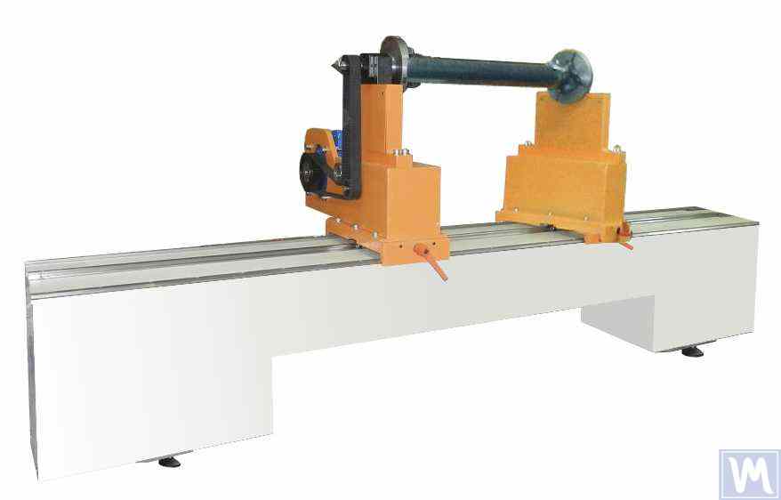
Figure 8. Balancing Machine for Driveshafts up to 2 Meters Long, Weighing up to 500 kg
The model has 2 stands and allows balancing in 2 correction planes.
Balancing Machine for Driveshafts up to 4200 mm Long, Weighing up to 400 kg
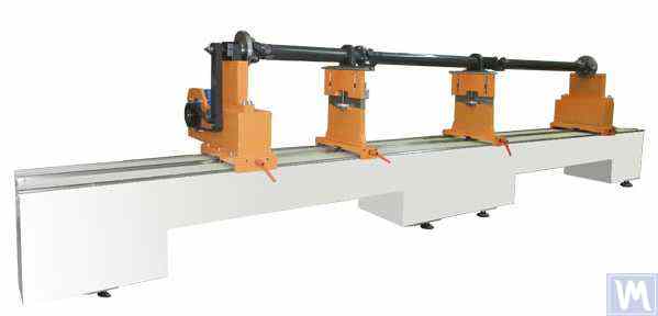
Figure 9. Balancing Machine for Driveshafts up to 4200 mm Long, Weighing up to 400 kg
The model has 4 stands and allows balancing in 4 correction planes simultaneously.
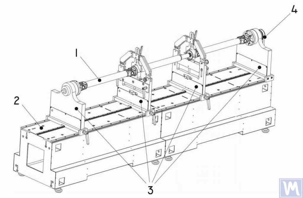
Figure 10. Horizontal Hard Bearing Balancing Machine for Dynamic Balancing of Driveshafts
1 – Balancing item (driveshaft); 2 – Machine base; 3 – Machine supports; 4 – Machine drive; The structural elements of the machine supports are shown in Figure 9.
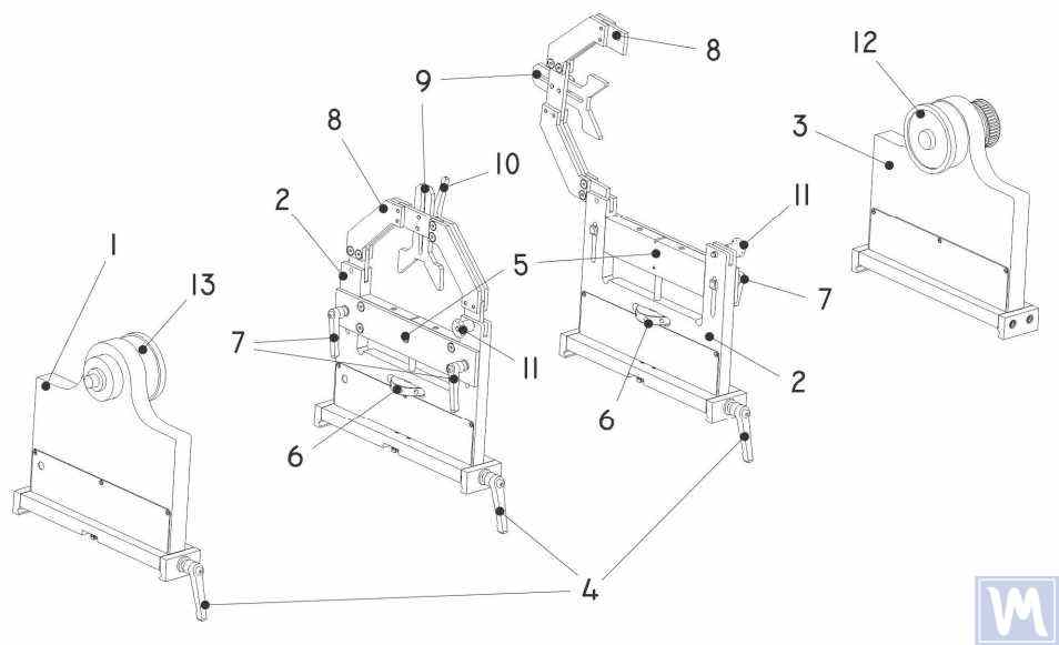
Figure 11. Machine Support Elements for Dynamic Balancing of Driveshafts
1 – Left non-adjustable support; 2 – Intermediate adjustable support (2 pcs.); 3 – Right non-adjustable fixed support; 4 – Support frame lock handle; 5 – Movable support platform; 6 – Support vertical adjustment nut; 7 – Vertical position lock handles; 8 – Support clamping bracket; 9 – Intermediate bearing movable clamp; 10 – Clamp lock handle; 11 – Clamping bracket lock; 12 – Drive (leading) spindle for item installation; 13 – Driven spindle
5. Preparation for Driveshaft Balancing
Below, we will consider the setup of the machine supports and the installation of the balancing item (four-support driveshaft) on the machine supports.
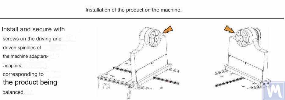
Figure 12. Installation of Transitional Flanges on the Spindles of the Balancing Machine
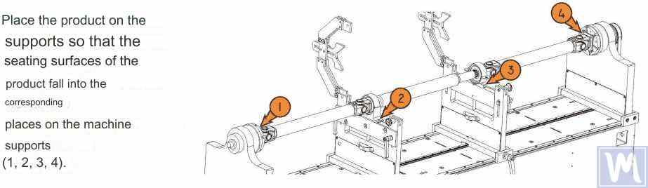
Figure 13. Installation of the Driveshaft on the Supports of the Balancing Machine
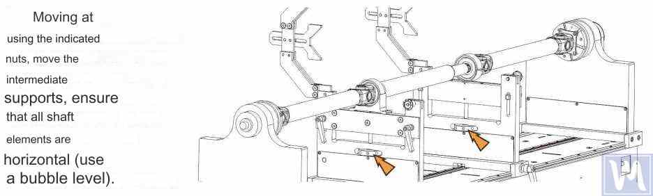
Figure 14. Leveling the Driveshaft Horizontally on the Supports of the Balancing Machine Using a Bubble Level
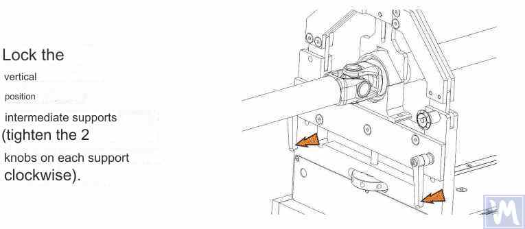
Figure 15. Fixing the Intermediate Supports of the Balancing Machine to Prevent Vertical Displacement of the Driveshaft
Rotate the item manually for a full turn. Ensure that it rotates freely and without jamming on the supports. After this, the mechanical part of the machine is set up, and the item installation is complete.
6. Driveshaft Balancing Procedure
The process of driveshaft balancing on the balancing machine will be considered using the Balanset-4 measuring system as an example. The Balanset-4 is a portable balancing kit designed for balancing in one, two, three, and four correction planes of rotors, either rotating in their own bearings or mounted on a balancing machine. The device includes up to four vibration sensors, a phase angle sensor, a four-channel measuring unit, and a portable computer.
The entire balancing process, including measurement, processing, and display of information on the magnitude and location of corrective weights, is performed automatically and does not require the user to have additional skills and knowledge beyond the provided instructions. The results of all balancing operations are saved in the Balancing Archive and can be printed as reports if necessary. In addition to balancing, the Balanset-4 can also be used as a regular vibro-tachometer, allowing measurement on four channels of the root mean square (RMS) value of total vibration, RMS of the rotational component of vibration, and control of rotor rotation frequency.
Furthermore, the device allows displaying graphs of the time function and vibration spectrum by vibration velocity, which can be useful in assessing the technical condition of the balanced machine.
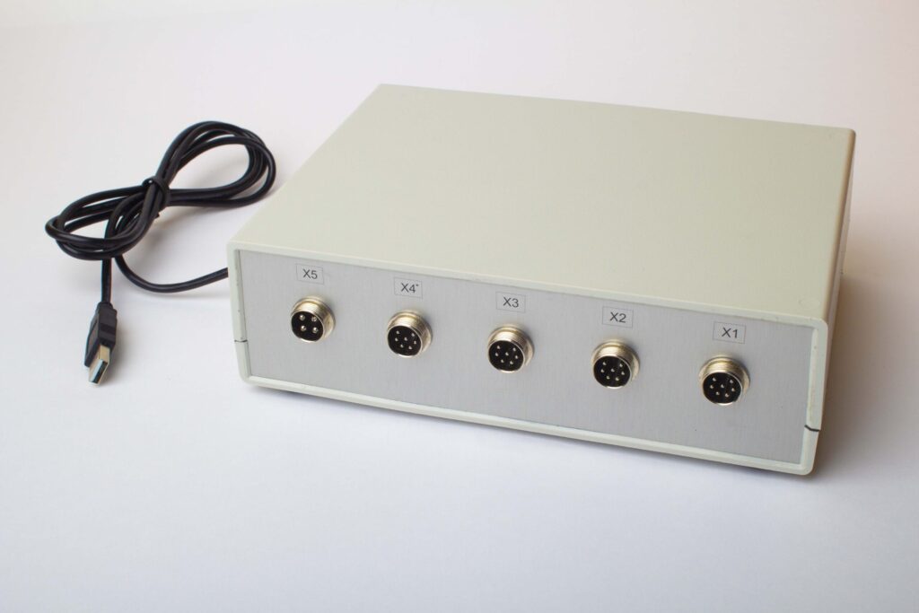
Figure 16. External View of the Balanset-4 Device for Use as a Measuring and Computing System of the Driveshaft Balancing Machine
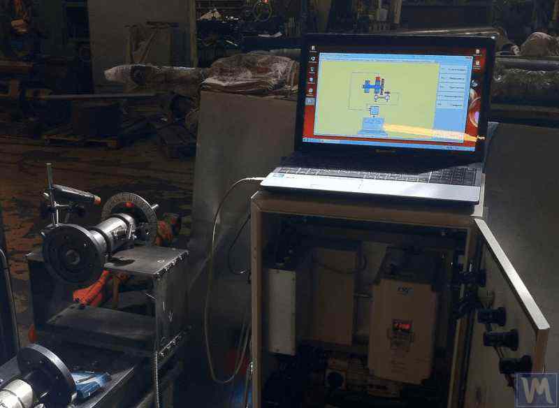
Figure 17. Example of Using the Balanset-4 Device as a Measuring and Computing System of the Driveshaft Balancing Machine
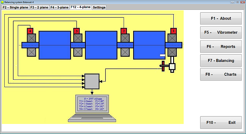
Figure 18. User Interface of the Balanset-4 Device
يُمكن تجهيز جهاز Balanset-4 بنوعين من المستشعرات: مقاييس تسارع الاهتزاز لقياس الاهتزاز (تسارع الاهتزاز)، ومستشعرات القوة. تُستخدم مستشعرات الاهتزاز في آلات الموازنة ما بعد الرنين، بينما تُستخدم مستشعرات القوة في آلات الموازنة ما قبل الرنين.
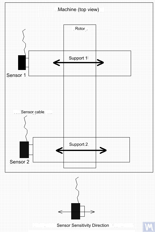
Figure 19. Installation of Balanset-4 Vibration Sensors on the Supports of the Balancing Machine
يجب أن يتطابق اتجاه محور حساسية المستشعرات مع اتجاه إزاحة اهتزاز الدعامة، أي أفقيًا في هذه الحالة. لمزيد من المعلومات حول تركيب المستشعر، يُرجى مراجعة قسم "موازنة الدوارات في ظروف التشغيل". يعتمد تركيب مستشعرات القوة على خصائص تصميم الآلة.
- Install vibration sensors 1, 2, 3, 4 on the supports of the balancing machine.
- Connect the vibration sensors to connectors X1, X2, X3, X4.
- Install the phase angle sensor (laser tachometer) 5 so that the nominal gap between the radial (or end) surface of the balanced rotor and the sensor housing is in the range of 10 to 300 mm.
- Attach a reflective tape mark with a width of at least 10-15 mm to the rotor surface.
- Connect the phase angle sensor to connector X5.
- Connect the measuring unit to the computer’s USB port.
- When using mains power, connect the computer to the power supply unit.
- Connect the power supply unit to a 220 V, 50 Hz network.
- Turn on the computer and select the “BalCom-4” program.
- Press the “F12-four-plane” button (or the F12 function key on the computer keyboard) to select the mode for measuring vibration simultaneously in four planes using vibration sensors 1, 2, 3, 4, connected respectively to inputs X1, X2, X3, and X4 of the measuring unit.
- A mnemonic diagram illustrating the process of measuring vibration simultaneously on four measurement channels (or the process of balancing in four planes) appears on the computer display, as shown in Figure 16.
Before performing balancing, it is recommended to take measurements in the vibrometer mode (F5 button).
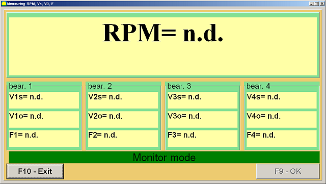
Figure 20. Vibrometer Mode Measurements
إذا كان إجمالي مقدار الاهتزاز V1s (V2s) يتطابق تقريبًا مع مقدار الاهتزاز للمكون الدوراني V1o (V2o)، فيمكن افتراض أن السبب الرئيسي لاهتزاز الآلية هو اختلال توازن الدوار. أما إذا تجاوز إجمالي مقدار الاهتزاز V1s (V2s) بشكل ملحوظ مقدار الاهتزاز للمكون الدوراني V1o (V2o)، فيُنصح بفحص الآلية - فحص حالة المحامل، والتأكد من تثبيتها بإحكام على القاعدة، والتأكد من عدم ملامسة الدوار للأجزاء الثابتة أثناء الدوران، ومراعاة تأثير الاهتزازات الصادرة عن الآليات الأخرى، وما إلى ذلك.
يمكن أن تكون دراسة الرسوم البيانية لدالة الوقت وأطياف الاهتزاز التي تم الحصول عليها في وضع "تحليل الرسوم البيانية الطيفية" مفيدة هنا.
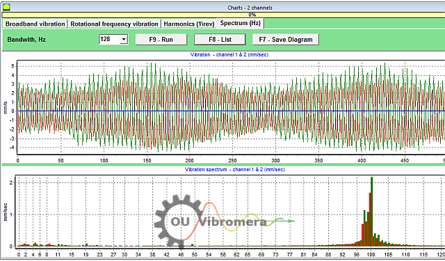
Figure 21. Vibration Time Function and Spectrum Graphs
يوضح الرسم البياني أعلى ترددات لمستويات الاهتزاز. إذا اختلفت هذه الترددات عن تردد دوران دوار آلية التوازن، فمن الضروري تحديد مصادر هذه الاهتزازات واتخاذ الإجراءات اللازمة لإزالتها قبل الموازنة.
It is also important to pay attention to the stability of the readings in vibrometer mode – the amplitude and phase of the vibration should not change by more than 10-15% during measurement. Otherwise, the mechanism might be operating near a resonance region. In this case, the rotor speed should be adjusted.
عند إجراء موازنة رباعية المستويات في الوضع "الأساسي"، يلزم إجراء خمس عمليات معايرة ومرة واحدة على الأقل للتحقق من الآلة المتوازنة. يُجرى قياس الاهتزاز خلال أول عملية معايرة للآلة بدون وزن تجريبي في مساحة عمل "موازنة رباعية المستويات". تُجرى عمليات المعايرة اللاحقة باستخدام وزن تجريبي، يُركّب بالتتابع على عمود الدفع في كل مستوى تصحيح (في منطقة كل دعامة لآلة الموازنة).
Before each subsequent run, the following steps should be taken:
- إيقاف دوران دوار الآلة المتوازنة.
- Remove the previously installed trial weight.
- Install the trial weight in the next plane.
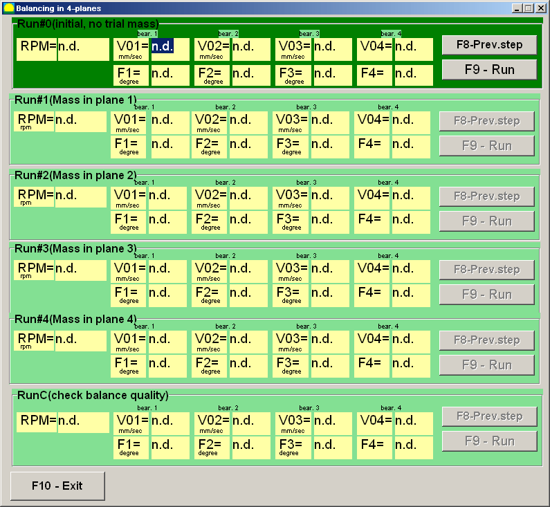
Figure 23. Four-Plane Balancing Workspace
بعد الانتهاء من كل قياس، يتم الحصول على نتائج تردد دوران الدوار (Nob), as well as the RMS values (Vo1، الخامسo2، الخامسo3، الخامسo4) and the phases (F1, F2, F3, F4) للاهتزاز عند تردد دوران الدوار المتوازن، تُحفظ في الحقول المقابلة في نافذة البرنامج. بعد التشغيل الخامس (الوزن في المستوى 4)، تظهر مساحة عمل "أوزان الموازنة" (انظر الشكل 24)، حيث تعرض القيم المحسوبة للكتل (م³).1, M2, M3, M4) and the installation angles (f1, f2, f3, f4) of the corrective weights that need to be installed on the rotor in four planes to compensate for its imbalance.
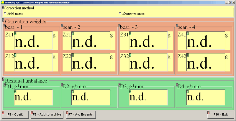
Figure 24. Workspace with Calculated Parameters of Corrective Weights in Four Planes
انتباه! بعد إتمام عملية القياس خلال الجولة الخامسة من تشغيل الآلة المتوازنة، يجب إيقاف دوران الدوار وإزالة وزن الاختبار المُثبّت سابقًا. بعد ذلك فقط، يُمكنك متابعة تركيب (أو إزالة) الأوزان التصحيحية على الدوار.
يُقاس الموضع الزاوي لإضافة (أو إزالة) الوزن التصحيحي على الدوار في نظام الإحداثيات القطبية من موقع تركيب الوزن التجريبي. يتطابق اتجاه قياس الزاوية مع اتجاه دوران الدوار. في حالة الموازنة باستخدام الشفرات، تتطابق شفرة الدوار المتوازن، التي تُعتبر، بشكل مشروط، الشفرة الأولى، مع موقع تركيب الوزن التجريبي. يتبع اتجاه ترقيم الشفرات الموضح على شاشة الكمبيوتر اتجاه دوران الدوار.
في هذا الإصدار من البرنامج، يُفترض افتراضيًا إضافة الوزن التصحيحي إلى الدوار. يُشار إلى ذلك بالعلامة المحددة في حقل "إضافة". إذا كان تصحيح الخلل بإزالة الوزن (مثلاً، بالحفر) ضروريًا، فاضبط العلامة في حقل "إزالة" باستخدام الفأرة، وبعد ذلك سيتغير الموضع الزاوي للوزن التصحيحي تلقائيًا بمقدار 180 درجة.
بعد تثبيت الأوزان التصحيحية على الدوار المتوازن، اضغط على زر "خروج - F10" (أو مفتاح الوظيفة F10 على لوحة مفاتيح الكمبيوتر) للعودة إلى مساحة عمل "موازنة المستويات الأربعة" السابقة والتحقق من فعالية عملية الموازنة. بعد إكمال عملية التحقق، ستظهر نتائج تردد دوران الدوار (N)ob) and the RMS values (Vo1، الخامسo2، الخامسo3، الخامسo4) and phases (F1, F2, F3, F4يتم حفظ قيم الاهتزازات عند تردد دوران الدوار المتوازن. في الوقت نفسه، تظهر مساحة عمل "أوزان الموازنة" (انظر الشكل 21) فوق مساحة عمل "موازنة المستويات الأربعة"، حيث تعرض المعلمات المحسوبة للأوزان التصحيحية الإضافية التي يجب تركيبها (أو إزالتها) على الدوار لتعويض اختلال التوازن المتبقي. بالإضافة إلى ذلك، تعرض مساحة العمل هذه قيم اختلال التوازن المتبقي المحقق بعد الموازنة. إذا كانت قيم الاهتزازات المتبقية و/أو اختلال التوازن المتبقي للدوار المتوازن تلبي متطلبات التسامح المحددة في الوثائق الفنية، فيمكن إكمال عملية الموازنة. وإلا، يمكن مواصلة عملية الموازنة. تتيح هذه الطريقة تصحيح الأخطاء المحتملة من خلال عمليات تقريب متتالية قد تحدث عند تركيب (إزالة) الوزن التصحيحي على الدوار المتوازن.
إذا استمرت عملية الموازنة، فيجب تثبيت (أو إزالة) أوزان تصحيحية إضافية على الدوار المتوازن وفقًا للمعلمات المحددة في مساحة العمل "أوزان الموازنة".
يتم استخدام زر "المعاملات - F8" (أو مفتاح الوظيفة F8 على لوحة مفاتيح الكمبيوتر) لعرض معاملات موازنة الدوار (معاملات التأثير الديناميكي) المحسوبة من نتائج عمليات المعايرة الخمس وحفظها في ذاكرة الكمبيوتر.
7. Recommended Balancing Accuracy Classes for Rigid Rotors
Table 2. Recommended Balancing Accuracy Classes for Rigid Rotors.

Recommended Balancing Accuracy Classes for Rigid Rotors
| Types of Machines (Rotors) | Balancing Accuracy Class | Value eper Ω mm/s |
|---|---|---|
| Drive crankshafts (structurally unbalanced) for large low-speed marine diesel engines (piston speed less than 9 m/s) | G 4000 | 4000 |
| Drive crankshafts (structurally balanced) for large low-speed marine diesel engines (piston speed less than 9 m/s) | G 1600 | 1600 |
| Drive crankshafts (structurally unbalanced) on vibration isolators | G 630 | 630 |
| Drive crankshafts (structurally unbalanced) on rigid supports | G 250 | 250 |
| Reciprocating engines assembled for passenger cars, trucks, and locomotives | G 100 | 100 |
| Automobile parts: wheels, wheel rims, wheelsets, transmissions | ||
| Drive crankshafts (structurally balanced) on vibration isolators | G 40 | 40 |
| Agricultural machines | G 16 | 16 |
| Drive crankshafts (balanced) on rigid supports | ||
| Crushers | ||
| Drive shafts (driveshafts, screw shafts) | ||
| Aircraft gas turbines | G 6.3 | 6.3 |
| Centrifuges (separators, settlers) | ||
| Electric motors and generators (with a shaft height of at least 80 mm) with a maximum nominal rotation speed of up to 950 min-1 | ||
| Electric motors with a shaft height of less than 80 mm | ||
| Fans | ||
| Gear drives | ||
| General-purpose machines | ||
| Metal cutting machines | ||
| Papermaking machines | ||
| Pumps | ||
| Turbochargers | ||
| Water turbines | ||
| Compressors | ||
| Computer-controlled drives | G 2.5 | 2.5 |
| Electric motors and generators (with a shaft height of at least 80 mm) with a maximum nominal rotation speed over 950 min-1 | ||
| Gas and steam turbines | ||
| Metal cutting machine drives | ||
| Textile machines | ||
| Audio and video equipment drives | G 1 | 1 |
| Grinding machine drives | ||
| Spindles and drives of high-precision equipment | G 0.4 | 0.4 |
الأسئلة الشائعة حول موازنة عمود القيادة
ما هو موازنة عمود القيادة؟
موازنة عمود الدفع هي عملية تصحيح أي خلل في كتلة عمود الدفع لضمان دورانه بسلاسة دون أي اهتزازات. تتضمن هذه العملية قياس موضع ثقل العمود على أحد الجانبين، ثم إضافة أو إزالة كميات صغيرة من الوزن (مثل لحام أوزان الموازنة) لموازنة هذا الخلل. يتحرك عمود الدفع المتوازن بالتساوي، مما يمنع الاهتزازات المفرطة والتآكل في مكونات السيارة.
لماذا يعد موازنة عمود القيادة أمرًا مهمًا؟
قد يؤدي عدم توازن عمود الدفع إلى اهتزازات قوية، خاصةً عند سرعات معينة، وقد يُصدر أصوات طقطقة أثناء التسارع أو تغيير التروس. مع مرور الوقت، قد تُتلف هذه الاهتزازات المحامل والوصلات العامة ومكونات نظام نقل الحركة الأخرى. يُزيل موازنة عمود الدفع هذه الاهتزازات، مما يضمن قيادة أكثر سلاسة، ويُقلل الضغط على الأجزاء، ويمنع التلف المُكلف أو توقف السيارة عن العمل.
ما هي الأعراض الشائعة لعمود القيادة غير المتوازن؟
تشمل الأعراض الشائعة لعمود نقل الحركة غير المتوازن أو المعيب اهتزازًا ملحوظًا أو ارتعاشًا في أرضية السيارة أو مقعدها، خاصةً مع زيادة السرعة. قد تسمع أيضًا أصوات طرق أو خشخشة عند تغيير التروس أو أثناء التسارع والتباطؤ. في بعض الحالات، قد ترتفع درجة حرارة المفصل العالمي بسبب اختلال التوازن. إذا لاحظت هذه العلامات، فمن المرجح أن عمود نقل الحركة بحاجة إلى موازنة أو إصلاح.
كيف تقوم بموازنة عمود القيادة؟
عادةً ما تُجرى موازنة عمود الدفع باستخدام آلة موازنة متخصصة. يُركّب عمود الدفع ويُدار بسرعة عالية بينما تكتشف المستشعرات أي خلل. ثم يُثبّت الفني أوزانًا صغيرة على عمود الدفع (أو يُزيل المواد) في مواضع محددة بناءً على قراءات الآلة. تُكرّر هذه العملية حتى يدور عمود الدفع دون اهتزاز يُذكر. تُمكّن الأنظمة الحديثة، مثل Balanset-4، من توجيه هذه العملية وحساب مكان وكمية الوزن المُضافة بدقة لتحقيق موازنة دقيقة.
Conclusion
وفي الختام، يعد تحقيق التوازن الصحيح لعمود القيادة أمرًا ضروريًا للسلامة والأداء وتوفير التكاليف. من خلال اكتشاف اختلال التوازن وتصحيحه، يمكنك منع التآكل غير الضروري للأجزاء، وتجنب الأعطال الضارة، والحفاظ على الأداء الأمثل للماكينة. أنظمة الموازنة الحديثة، مثل جهازي Balanset-1 وBalanset-4، تجعل العملية أكثر كفاءة، مما يساعد حتى الورش الصغيرة على تحقيق نتائج احترافية.
إذا كنت تعاني من اهتزازات مستمرة في عمود نقل الحركة أو كنت بحاجة إلى حل موازنة موثوق، فلا تتردد في اتخاذ الإجراء اللازم. اتبع الخطوات الموضحة في هذا الدليل أو استشر خبرائنا للحصول على المساعدة. باتباع النهج الصحيح والمعدات المناسبة، يمكنك ضمان عمل عمود نقل الحركة بسلاسة وموثوقية لسنوات قادمة. اتصل بنا لمعرفة المزيد أو لاستكشاف أفضل معدات موازنة عمود القيادة التي تناسب احتياجاتك.

0 تعليقات