Usluge balansiranja › Ventilatori, rotori i mihaljevi
Uravnotežavanje ventilatora i mihalja — na mjestu, pri radnoj brzini
Industrijski ventilatori, radijalni i aksijalni rotori, izvlačni ventilatori i mihaljevi vibriraju čim se nakuplja prašina, lopatice trošu ili popravka pomakne težinu. Uravnotežavamo ih na mjestu, pri radnoj brzini — bez uklanjanja iz kanala ili kućišta — eliminirajući uzrok propasti ležajeva, pukotina u konstrükaciji i gubitka energije u jednoj sesiji na mjestu.
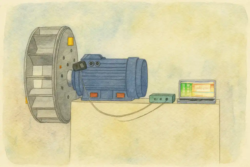
In short: Balansiranje ventilatora i puhača izvršava se na mjestu (in-situ), pri normalnoj brzini rada, koristeći metodu koeficijenta uticaja. Vibracijski akcelerometar na kućištu ležaja i laserski tahometar na vratilu mjere stanje neuravnoteženosti; Balanset-1A izračunava točnu korekcijsku masu i kutnu poziciju. Bez potrebe za skidanjem ventilatora, bez odvajanja kanala – tipičan posao u jednoj ravnini je gotov za manje od jedan sat, smanjujući vibracije za 70 % ili više i produžavajući trajnost ležaja osam ili više puta.
Znakovi da je vaš ventilator ili puhač neuravnotežen
Impeleri ventilatora su najmanje česti posao balansiranja na mjestu (in-situ) – a simptomi se lako prepoznaju čim ih znate:
Zašto ventilatoru nestaje balansa – i šta to košta
Ventilator napušta tvoricu uravnotežen, ali radni vijek neprekidno napada to stanje. Neravnomjerna nakupljanja prašine i proizvoda na lopaticama je najčešći uzrok: čak i tanka asimetrična sloja na jednoj lopatici dodaje dovoljno mase da generiše značajnu centrifugalnu silu pri punoj brzini. Erozija abrazivnim materijalom uklanja materijal s prednjeg ruba neravnomjerno; corrosion razara jednu stranu impelera prije druge; oštećenja od udaraca prikupljenih stranih predmeta savijaju ili čipaju pojedine lopatice; a teške lopate za zavaravanje ili zamjenske lopatice dodaju lokalizirane mase što pomjera centar gravitacije dalje od ose vratila.
Budući da centrifugalna sila raste s kvadratom square brzine rotacije, čak i nekoliko grama pomjeraja mase na 1.500 o/min postaje stotine njutna sile vibracija — pomnoženo na hiljade njutna na 3.000 o/min. Ako se ostavi bez ispravljanja, ta ciklična sila uništava ležajeve i brtvenice, puca rotor i okolnu konstrukciju, rasipa se električna energija i na kraju forsirava neplanirano zaustavljanje cijele procesne linije. Jedna sesija terenske balanciranja — često manja od sat vremena na mjestu — uklanja uzrok umjesto da se stalno zamjenjuju komponente koje uništava.
Zašto polavljenje vibracija mnogostruko produžava vijek trajanja ležaja
Kako balanciramo ventilator — korak po korak
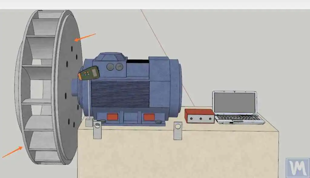
Terenska balanciranja sa Balanset-1A slijedi metod koeficijenata uticaja — istu sistematsku proceduru koju možete sprovesti sami na mjestu, bez demontaže ventilatora iz njene kućišta:
- Montaža senzora. Vibracijski akselerometar se pričvrsti na kućište ležaja ventilatora a laserski tahometar se usmjeri na reflektujuću traku na vratilu ili centrifugalnoj rozetici. Nije potrebna demontaža — ventilator se nastavlja sa normalnom radnom brzinom tokom cijelog procesa.
- Izmjerite baznu vrijednost. Jedan prolaz pri punoj radnoj brzini bilježi amplitudu vibracija i kut faznog pomaka, établi uspostavljajući trenutno stanje neuravnoteženosti u magnitudu i smjeru.
- Dodajte probnu masu. Poznata testna masa se pričvrsti ili priveže na lopaticu ili centrifugalnoj rozetici na poznatoj kutnoj poziciji. Drugi pokret pokazuje kako se rotor odziva — to je koeficijent uticaja.
- Dozvoli uređaju da izračuna. Balanset-1A primjenjuje algoritam koeficijenata uticaja da izračuna tačnu masu korekcije i kutnu poziciju — jednu ravninu za uske diskaste rotore, dvije ravnine za široke dvoulazne rotore ili dugačke sklopove vratila.
- Montaž korekcijske mase. Zavarenu, zakovano, prikovanu ili pričvrsti izračunatu masu na navedenu poziciju na lopatici, vrhu lopatice ili centrifugalnoj rozetici. Uklonite testnu masu osim ako nije dio rješenja.
- Provjerite i dokumentirajte. Završni pokus mjerenja potvrđuje da je rezidualna nebalansiramnost u okviru ISO tolerancijskog pojasa za kategoriju primjene ventilatora. Balanset-1A čuva izvještaj o balanciranju za vaše zapisnike održavanja.
Što balansiramo
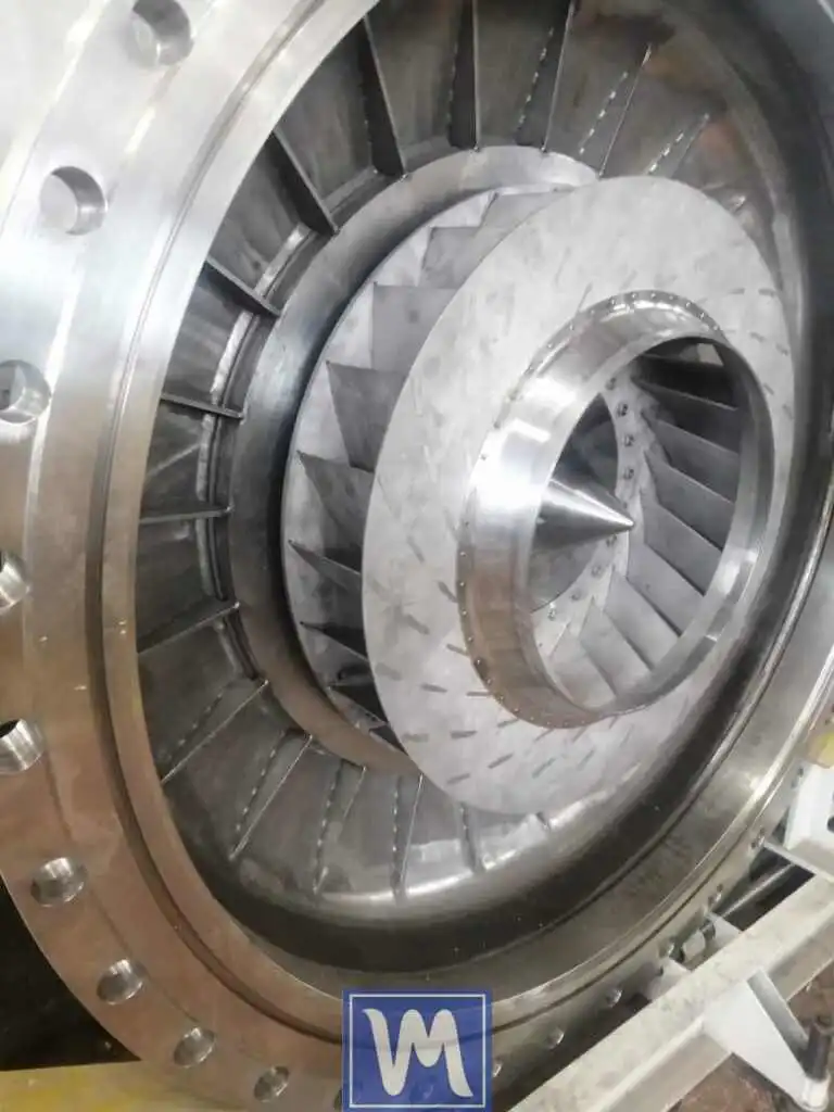
- Centrifugalni (radijalni) rotori ventilatora
- Aksijalni i vanski aksijalni ventilatori
- Ventilatori za ID/FD kotlove i peći
- Ispušni ventilatori i usisivači prašine
- Industrijske puhaljke i pokretači zraka visokog pritiska
- Ventilatori rashladnih tornjeva
- HVAC dovodne i povratne ventilatore zraka
- Dvoulazni (dvopločni) rotori
- Rotori sa unatrag zakrivljenim i naprijed zakrivljenim lopaticama
- Mali rashladni i preciozni mikro ventilatori
Tolerancije i standardi
ISO 14694 postavlja granice kvalitete balanciranja i brzine vibracija specijalnih industrijskih ventilatora, organizirane po kategoriji primjene BV-1 (opća ventilacija, niski zahtjevi vibracija) kroz BV-5 (precizni procesni ventilatori, najtanja tolerancija). Dozvoljeno rezidualna nebalansiramnost po kategoriji primjene određuje koje ISO 21940-11 G-klase primjenjuje.
ISO 21940-11 (prije ISO 1940-1) definiše klase kvalitete balanciranja krutih rotora G0.4 do G4000. Većina industrijskih procesnih ventilatora je balansirano na G2.5 or G1.0; HVAC dovodni i povratni ventilatori su obično do G6.3. Formula je: dozvoljeni specifični nebalancirani moment (g·mm/kg) = G × 9549 / n, gdje je n maksimalna radna brzina u rpm. Koristite naš kalkulator rezidualne neuravnoteženosti da pronađete vašu toleranciju prije nego što počnete. Balansiram na razredu koji zahtijeva vaša primjena i dokumentiram postignuti brojka preostale nebalanciranosti u izvještaju o balansiranju.
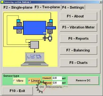
Balanset-1A — vaš kompletan komplet za balansiranje na terenu
Sve što je na ovoj stranici obavljeno je jednim prenosivim instrumentom: sa Balanset-1A. To je dvokanalski dinamički balancer i analizator vibracija koji balansira rotore ventilatora i puhala u njihovim sopstvenim ležajevima, pri radnoj brzini, koristeći metodu sa tri pokreta koeficijenta uticaja — softver izračunava tačnu masu i ugao korekcije i čuva izveštaj.
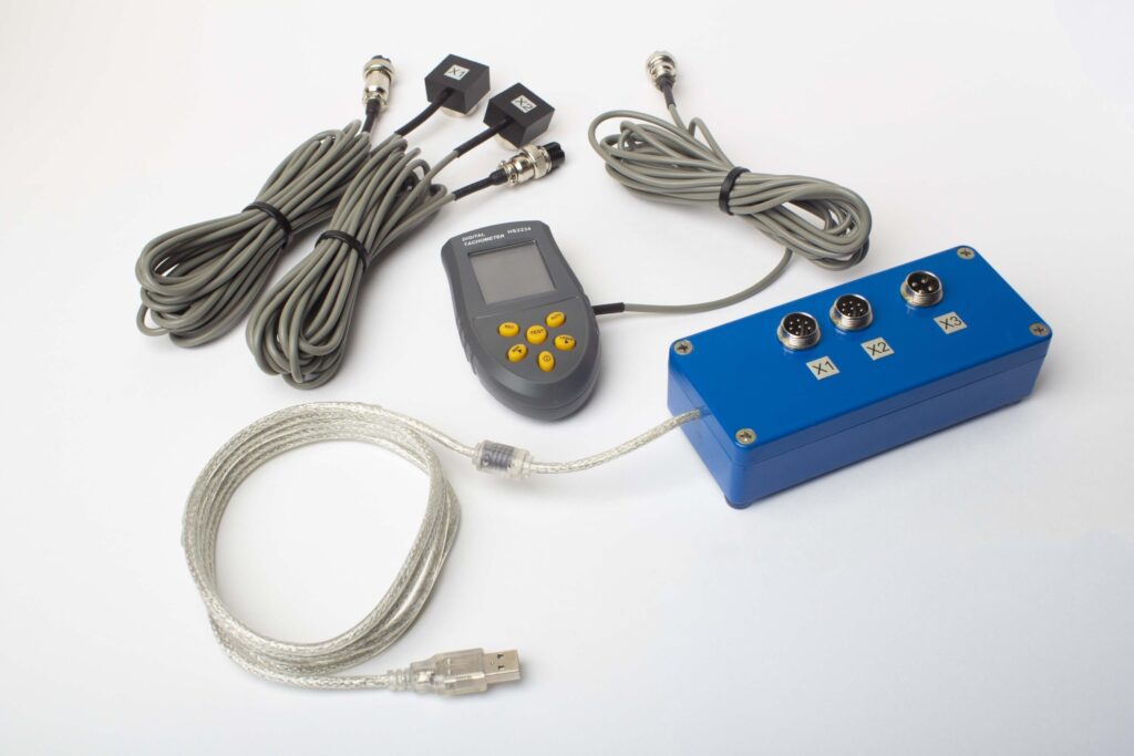
Šta se nalazi u kompletu
€1,975 · Kompletan komplet, dostupan, račun sa PDV-om
- Interfejsna mernajedinca (USB, 2 kanala)
- Dva akceleromera za vibracije (4 m kabel, 10 m opciono)
- Laserski tahometar / optički senzor faze (50–500 mm)
- Magnetni stalak za senzor
- Digitalna vaga za probne i korektivne težine
- Windows softver za balansiranje i analizu
- Plastični transportni kofer
Full Kit
Uređaj · 2 senzora · laserski tahometar · magnetni stalak · digitalna vaga · softver · transportni kofer. Sve što je potrebno da počnete sa balansiranjem ventilatora i puhala iz kutije.
OEM set
Uređaj · 2 senzora · laserski tahometar · softver. Za integratere koji već imaju stalak, vagu i kofer, ili koji ugrađuju uređaj u namenski rig za balansiranje ventilatora.
| Parameter | Value |
|---|---|
| Kanali merenja | 2 (jednoplanski i dvoplanski balans) |
| Raspon brzine vibracije | 0.2–80 mm/s RMS |
| Raspon frekvencije | 5–1000 Hz (≤10% amplitude error above 550 Hz) |
| Tačnost mjerenja | ±5% pune skale |
| Method | 3-prolazni koeficijent uticaja (1 ili 2 ravni) |
| Analysis | Amplituda i faza na 1×, FFT spektar i talasni oblik, sačuvana izvještaja |
| Laptop | Nije uključeno (Windows PC, dostupno na zahtjev) |
Terenske balansiranje nasuprot balanciranju na mašini — šta je pravo za vaš ventilator?
| Factor | Balansiranje u pogonu (Balanset-1A) | Stroj za balansiranje (radionica) |
|---|---|---|
| Ventilator uklonjen iz kanala/kućišta? | Ne — radi u mjestu | Da — potrebno potpuno rastavljanje |
| Odvajanje kanala? | No | Yes |
| Zastoj proizvodnje | Samo ugradnja senzora (<15 min) | Sati do dana (demontaža, transport, balansiranje, ponovno postavljanje) |
| Brzina balansiranja | Stvarna operativna brzina & uvjeti | Odvojena niskobrzinska vretena |
| Uzima u obzir fleksibilnost vratila i spajač | Da — kompletan sklop balansiran u realnim uslovima | Samo radni dio, bez dinamike vratila |
| Standards met | ISO 14694, ISO 21940-11 | ISO 21940-11 |
| Equipment cost | €1,975 (Kompletna oprema) | €10,000 – €50,000+ |
| Tipično vrijeme posla | <1 sat na terenu | 1–3 dana ukupno |
Terenske balansiranje je preferirani izbor kad god ventilator može raditi i kriterij rigidnosti rotora je zadovoljen. Radionica za balansiranje ostaje prikladna za nove lopatice koje nikad nisu rotirala, ili za rotore koje je potrebno rastaviti za zamjenu lopatica ili glavnu popravku prije ponovnog balansiranja.
Pravi slučajevi balansiranja ventilatora
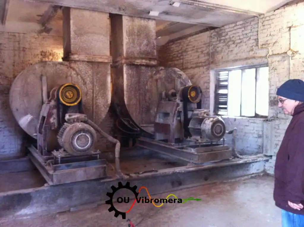
Industrijska balansiranje ventilatora
Dvoplanski terenske balansiranje velikog industrijskog centrifugalnog ventilatora pri radnoj brzini.
Vodič za balansiranje ispušnog ventilatora
Korak-po-korak procedura in-situ za HVAC ispušni ventilator, sa dokumentiranim rezultatima.
Industrijska puhala
Dinamička balansiranja na mjestu rotora kompresora visokog pritiska prema ISO 14694 tolerancijama.
Radijalni ventilatorski rotor
Jednostavna balansiranja rotora centrifugalnog radialnog ventilatora, korekcijska masa zavarena na glavinu.
Mali ventilatori i hladnjaci
Precizna balansiranja malih hladnih ventilatora gdje su čak i miligamske korekcije važne.
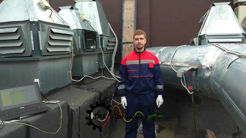
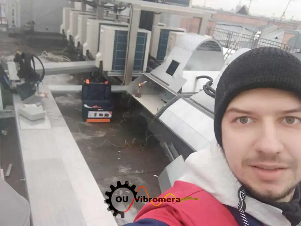
Ispušni ventilator na mjestu rada
Balansiranje ispušnog ventilatora na mjestu bez odvajanja cjevovoda.
Besplatni kalkulatori za balansiranje ventilatora
Često postavljana pitanja o balansiranju ventilatora
Treba li ventilator biti uklonjen iz kanala ili kućišta za balansiranje?
Kada je potrebna jednostavna balansiranja nasuprot dvostranoj balansiranju?
Moj ventilator i dalje vibrira nakon čišćenja lopatica — je li to neravnoteža?
Koliko dugo traje tipična balansiranja ventilatora?
Mogu li naš tim za održavanje to učiniti sami sa Balanset-1A?
Koji razred balansiranja moraju ispuniti ventilatori i kako se on izračunava?
Naučite teoriju
Balansirajte svoj ventilator na mjestu — danas
Balanset-1A vas vodi kroz jednostavno- i dvoslojno balansiranje ventilatora i puhala pri brzini rada, izračunava točnu masu korekcije i kut, te dokumentira rezultat u skladu s ISO 14694 i ISO 21940-11. Bez demontaže, bez izgubljene proizvodnje — samo tiši, hladniji, duže trajan ventilator.
Primjer iz stvarnog svijeta: see kako je industrijski ventilator balansiран na mjestu s Balanset-1A — praktični primjer na terenu korak po korak.
