
PRIJENOSNI BALANSER "BALANSET-1A"
Dvokanalnog PC-baziranog sistema za dinamičko balansiranje
UPUTSTVO ZA UPOTREBU
rev. 1.56 maj 2023
2023 | Estonija, Narva
SIGURNOSNA NAPOMENA: Ovaj uređaj je u skladu sa EU normama sigurnosti. Laserski proizvod klase 2. Pratite procedure sigurnosti rotacijske opreme. Pogledajte sve informacije o sigurnosti ispod →
1. PREGLED SISTEMA ZA BALANSIRANJE
Balanset-1A balanser omogućava usluge jednoravnog i dvostrukoravnog dinamičkog uravnoteživanja za ventilatore, brusne ploče, vretena, drobilice, pumpe i druge rotirajuće mašine.
Balanset-1A uravnotežavač uključuje dva vibrosenzora (akserometara), laserski senzor faze (tahometar), 2-kanalni USB interfejs sa predojačivačima, integratorima i ADC modulom za prikupljanje podataka i Windows softvera za uravnoteživanje. Balanset-1A zahteva prijenosno računalo ili drugi Windows (WinXP...Win11, 32 ili 64bit) kompatibilan računar.
Softver za balansiranje pruža ispravno rješenje za balansiranje u jednoj i dvije ravni automatski. Balanset-1A jednostavan je za upotrebu i za one koji nisu stručnjaci za vibracije.
Svi rezultati balansiranja se čuvaju u arhivi i mogu se koristiti za kreiranje izvještaja.
Ključne karakteristike
Jednostavan za upotrebu
- • Pokusna masa - izbor korisnika
- • Popup validnosti pokusne mase
- • Ručni unos podataka
Mogućnosti mjerenja
- • Broj okretaja, amplituda i faza
- • FFT spektralna analiza
- • Prikaz talasa i spektra
- • Istovremeni podaci dvaju kanala
Napredne funkcije
- • Sačuvani koeficijenti uticaja
- • Finije uravnoteživanje
- • Proračun ekscentričnosti mandre
- • Proračun tolerancije ISO 1940
Upravljanje podacima
- • Neograničena pohrana podataka o balansiranju
- • Pohrana talasnog oblika vibracija
- • Arhiva i izvještaji
Alati za proračun
- • Proračun podijeljene težine
- • Proračun bušenja
- • Promjena ravnina korekcije
- • Vizuelizacija polarnog grafa
Opcije analize
- • Uklanjanje ili zadržavanje pokusnih težina
- • Grafikoni RunDown (eksperimentalno)
2. SPECIFIKACIJA
| Parametar | Specifikacija |
|---|---|
| Mjerni opseg srednje kvadratne vrijednosti (RMS) brzine vibracije, mm/sec (za 1x vibraciju) | od 0,02 do 80 |
| Frekvencijski opseg RMS mjerenja brzine vibracije, Hz | od 5 do 1000 (greška amplitude ≤10% od 5 do 550 Hz; do 20% od 550 do 1000 Hz) |
| Broj ravni korekcije | 1 ili 2 |
| Opseg mjerenja frekvencije rotacije, o/min | 100 – 100000 |
| Opseg mjerenja faze vibracije, ugaoni stepeni | od 0 do 360 |
| Greška mjerenja faze vibracije, ugaoni stepeni | ± 1 |
| Tačnost mjerenja RMS brzine vibracija | ±(0.1 + 0.1×Vizmjereno) mm/s |
| Tačnost mjerenja frekvencije rotacije | ±(1 + 0.005×Nizmjereno) o/min |
| Srednje vrijeme između kvarova (MTBF), sati, min | 1000 |
| Prosječni vijek trajanja, godine, min | 6 |
| Dimenzije (u tvrdom koferu), cm | 39*33*13 |
| Masa, kg | <5 |
| Ukupne dimenzije senzora vibratora, mm, maks | 25*25*20 |
| Masa senzora vibratora, kg, maks | 0.04 |
|
Uslovi rada: - Temperaturni opseg: od 5°C do 50°C - Relativna vlažnost: < 85%, nezasićena - Bez jakog elektromagnetskog polja i jakih udara |
|
3. PAKET
Balanset-1A uključuje dva jednoosnovna akcelerometra, laserski marker za referencu faze (digitalni tahometar), 2-kanalni USB interfejsni modul sa predpojačivačima, integratorima i ADC modulom za prikupljanje podataka te Windows software za balansiranje.
Isporučeni komplet
| Opis | Broj | Bilješka |
|---|---|---|
| USB interfejs jedinica | 1 | |
| Referentni marker laserske faze (tahometar) | 1 | |
| Jednoosnovna akcelerometra | 2 | |
| Magnetno postolje | 1 | |
| Digitalne vage | 1 | |
| Tvrdi kofer za transport | 1 | |
| "Balanset-1A". Korisničko uputstvo. | 1 | |
| Flash disk sa softverom za balansiranje | 1 |
4. PRINCIPI BALANSIRANJA
4.1. "Balanset-1A" uključuje (sl. 4.1) USB interfejsni modul (1), dva akcelerometra (2) i (3), marker za referencu faze (4) i prijenosno računalo (nije uključeno) (5).
Komplet isporuke također uključuje magnetni stalak (6) koristi se za montažu referentnog markera faze i digitalnih vaga 7.
Konektori X1 i X2 namijenjeni su za povezivanje senzora vibracija sa 1. i 2. mjernim kanalom, a konektor X3 koristi se za povezivanje referentnog markera faze.
USB kabel obezbjeđuje napajanje i povezivanje USB interfejsne jedinice sa računarom.

Sl. 4.1. Komplet isporuke "Balanset-1A"
Mehaničke vibracije uzrokuju električni signal proporcionalan ubrzanju vibracija na izlazu senzora vibracija. Digitalizovani signali iz ADC modula prenose se putem USB-a na prenosivi računar (5). Marker za referencu faze generiše signal impulsa koji se koristi za izračunavanje frekvencije rotacije i ugla faze vibracije. Windows software nudi rješenja za balansiranje u jednoj i dvije ravnine, analizu spektra, dijagrame, izvještaje i pohranu koeficijenata utjecaja.
5. SIGURNOSNE MJERE OPREZA
⚡ OPASNOST - Električna sigurnost
5.1. Prilikom rada na 220V moraju se poštovati propisi o električnoj sigurnosti. Nije dozvoljeno popravljati uređaj dok je spojen na 220 V.
5.2. Ako koristite uređaj u okruženju slabe kvalitete napajanja AC strujom ili u prisustvu smetnji na mreži, preporučuje se korištenje baterije prijenosnog računala.
⚠️ Dodatni zahtjevi sigurnosti za rotirajuću opremu
- !Blokiranje mašine: Uvijek primijenite odgovarajuće procedure zaključavanja/označavanja prije instalacije senzora
- !Lična zaštitna oprema: Nositi zaštitne naočale, zaštitu za sluh i izbjegavati labavu odjeću blizu rotirajućih dijelova
- !Sigurna instalacija: Osigurati da su svi senzori i kablovi čvrsto učvršćeni i da ne mogu biti zahvaćeni rotirajućim dijelovima
- !Nužne mjere: Poznavati lokaciju zaustavnog gumba za hitne slučajeve i proceduru gašenja
- !Obuka: Samo obučeni osoblje smije raditi sa opremom za balansiranje na rotirajućim dijelovima
6. SOFTVERSKE I HARDVERSKE POSTAVKE
6.1. Instalacija USB drajvera i softvera za balansiranje
Prije rada instalirajte drajvere i softver za balansiranje.
Spisak foldera i datoteka
Instalacioni disk (flash drive) sadrži sljedeće fajlove i foldere:
- Bs1Av###Setup – folder sa softverom za balansiranje "Balanset-1A" (### – broj verzije)
- ArdDrv – USB drajveri
- EBalancer_manual.pdf – ovo uputstvo
- Bal1Av###Setup.exe – datoteka instalacije. Ova datoteka sadrži sve arhivirane datoteke i foldere navedene gore. ### – verzija softvera "Balanset-1A".
- Ebalanc.cfg – vrijednost osjetljivosti
- Bal.ini – neki podaci inicijalizacije
Procedura instalacije softvera
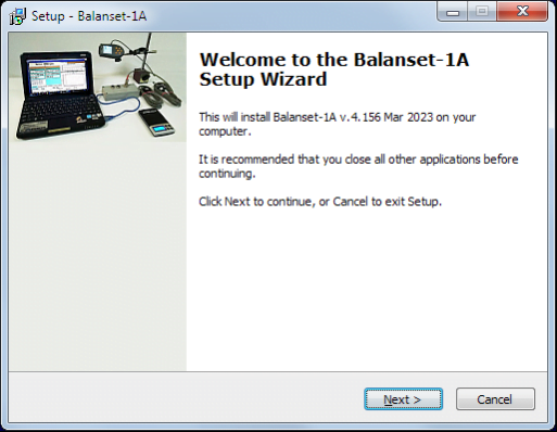
Za instalaciju drajvera i specijalizovanog softvera pokrenite fajl Bal1Av###Setup.exe i slijedite uputstva za instalaciju pritiskom na dugmad «Dalje», «ОК» itd.
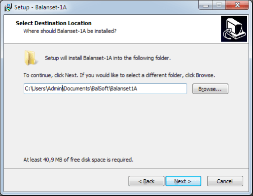
Izaberite folder za instalaciju. Obično se dati folder ne smije mijenjati.
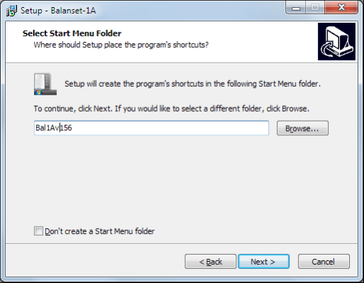
Zatim program zahtijeva specificiranje grupe programa i foldera na desktopu. Pritisnite dugme Dalje.
Završetak instalacije
- ✓Instalirajte senzore na inspekcioni ili balansirani mehanizam (Detaljne informacije o tome kako instalirati senzore date su u Prilogu 1)
- ✓Povežite senzore vibracija 2 i 3 sa ulazima X1 i X2, a senzor faznog ugla sa ulazom X3 USB interfejsne jedinice.
- ✓Povežite USB interfejsnu jedinicu sa USB portom računara.
- ✓Prilikom korištenja napajanja iz AC izvora, priključiti računar na mrežu. Priključiti napajanje na 220 V, 50 Hz.
- ✓Kliknuti na prečicu "Balanset-1A" na radnoj površini.
7. SOFTVER ZA BALANSIRANJE
7.1. Opšte informacije
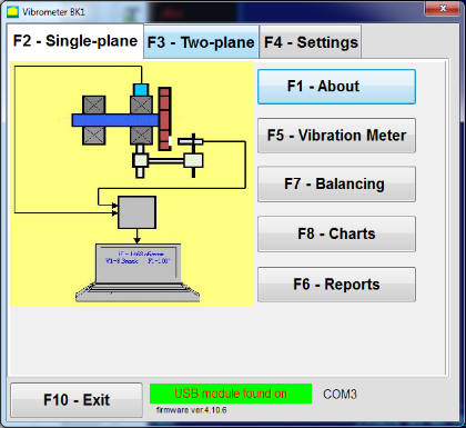
Početni prozor
Prilikom pokretanja programa "Balanset-1A" pojavljuje se početni prozor, prikazan na Sl. 7.1.

Sl. 7.1. Početni prozor "Balanset-1A"
U početnom prozoru nalaze se 4 dugmeta sa nazivima funkcija koje se realizuju klikom na njih.
F1-«O programu»
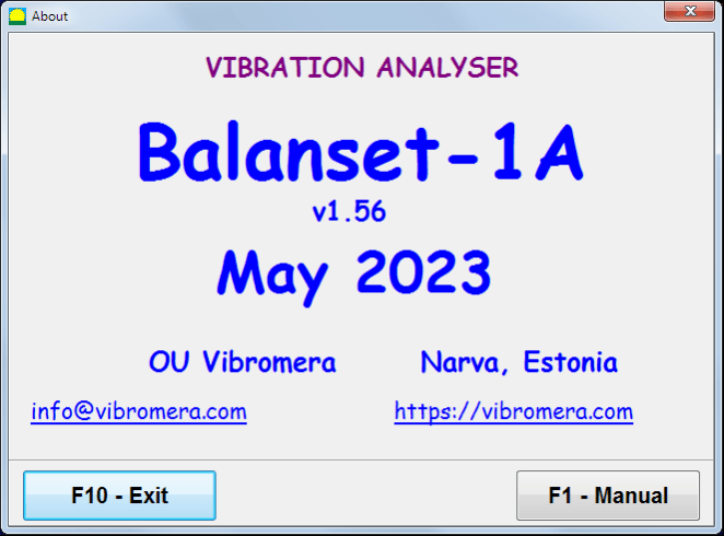
Sl. 7.2. Prozor F1–«O programu»
F2-«Jedna ravnina», F3-«Dvije ravnine»
Pritiskom na "F2- Jednoravninsko" (ili F2 funkcijsku tipku F2 na tastaturi računara) bira mjerenje vibracija na X1.
Nakon klika na ovo dugme, na ekranu računara se prikazuje dijagram prikazan na Sl. 7.1 koji ilustruje proces mjerenja vibracija samo na prvom mjernom kanalu (ili proces balansiranja u jednoj ravni).
Pritiskom na dugme "F3-Dvije ravnine" (ili F3 funkcijski taster na tastaturi računara) bira režim mjerenja vibracija na dva kanala X1 i X2 istovremeno. (Sl. 7.3.)
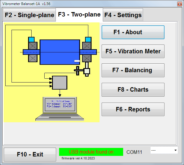
Sl. 7.3. Početni prozor "Balanset-1A". Balansiranje u dvije ravni.
F4 – "Postavke"
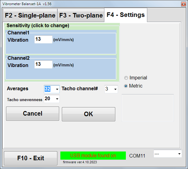
Sl. 7.4. Prozor "Postavke"
U ovom prozoru možete promijeniti neke postavke Balanset-1A.
- Osjetljivost. Nominalna vrijednost je 13 mV / mm/s.
Mijenjanje koeficijenata osjetljivosti senzora je potrebno samo pri zamjeni senzora!
Pažnja!
Kada unesete koeficijent osjetljivosti, njegov decimalni dio je odvojen od cijeloga dijela sa decimalnom točkom (znakom ",").
- Usrednjavanje - broj usrednjavanja (broj obrtaja rotora tokom kojih se podaci usrednjavaju radi veće tačnosti)
- Tahometarski kanal# - kanal na koji je priključen tahometar. Podrazumevanom - 3. kanal.
- Neravnomjernost - razlika u trajanju između susjednih impulsa tahometra koja iznad daje upozorenje "Neispravnost tahometra"
- Imperijalni/Metrički - Odaberite sistem jedinica.
Broj COM porta se dodjeljuje automatski.
F5 – "Mjerač vibracija"
Pritiskom na ovo dugme (ili funkcijsku tipku F5 na tastaturi računara) aktivira režim mjerenja vibracija na jednom ili dva mjerna kanala virtualnog mjerača vibracija, u zavisnosti od stanja dugmadi “F2-jedna ravnina", "F3-dvije ravni".
F6 – «Izvještaji»
Pritiskom na ovo dugme (ili F6 funkcijski taster na tastaturi računara) uključuje Arhivu balansiranja, iz koje možete štampati izvještaj sa rezultatima balansiranja za specifični mehanizam (rotor).
F7 – «Balansiranje»
Pritiskom na ovo dugme (ili funkcijsku tipku F7 na tastaturi) aktivira se režim balansiranja u jednoj ili dvije korekcijske ravnine, u zavisnosti od toga koji je režim mjerenja odabran pritiskom na dugmad “F2-jedna ravnina", "F3-dvije ravni".
F8 – «Grafikoni»
Pritiskom na ovo dugme (ili F8 funkcijsku tipku na tastaturi računara) omogućava grafički mjerač vibracija, čija realizacija na ekranu prikazuje istovremeno sa digitalnim vrijednostima amplitude i faze grafikon vremenske funkcije vibracija.
F10 – «Izlaz»
Pritiskom na ovo dugme (ili F10 tipka funkcije na računarskoj tipkovnici) završava program "Balanset-1A".
7.2. "Mjerač vibracija"
Prije rada u modu "Mjerač vibracija" način rada, instalirajte senzore vibracija na stroj i povežite ih redom na konektore X1 i X2 USB jedinice sučelja. Senzor tahometra treba biti priključen na ulaz X3 USB jedinice sučelja.

Sl. 7.5 USB interfejsna jedinica
Postavite reflektivnu traku na površinu rotora radi rada tahometra.

Sl. 7.6. Reflektivna traka.
Preporuke za instalaciju i konfiguraciju senzora date su u Prilogu 1.
Za početak mjerenja u modu Mjerač vibracija kliknite na dugme "F5 – Vibrometar" u početnom prozoru programa (vidjeti sl. 7.1).
Vibrometar prozor se otvara (vidi sl. 7.7)

Sl. 7.7. Način rada mjerača vibracija. Val i spektar.
Za početak mjerenja vibracija kliknite dugme "F9 – Pokreni" (ili pritisnite tipku funkcije F9 na tipkovnici).
Ako Način pokretanja Automatski je označeno – rezultati mjerenja vibracija će se periodično prikazivati na ekranu.
U slučaju istovremenog mjerenja vibracija na prvom i drugom kanalu, prozori smješteni ispod riječi “Ravan 1" i "Ravan 2" će biti popunjeno."
Mjerenje vibracija u režimu „Vibrometar” također se može izvesti sa isključenim senzorom faznog ugla. U početnom prozoru programa prikazat će se samo vrijednost ukupne RMS vibracije (V1s, V2s
U modu "Vibrometar" dostupna su sljedeća podešavanja
- RMS Nisko, Hz – najniža frekvencija za izračunavanje RMS-a ukupne vibracije
- Propusni opseg – propusni opseg frekvencije vibracije na grafikonu
- Prosjeci – broj usrednjavanja za veću tačnost mjerenja
Za završetak rada u modu "Vibrometar" kliknite gumb "F10 – Izlaz" i vratite se na početni prozor.

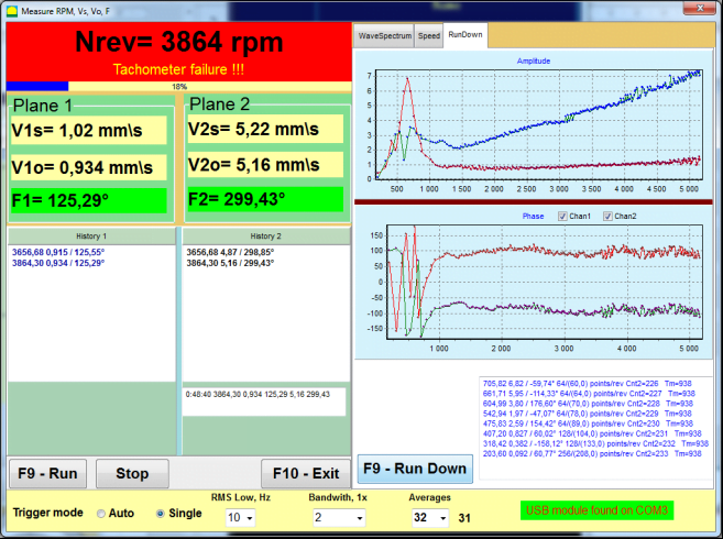
Sl. 7.8. Način rada mjerača vibracija. Brzina rotacije, neravnina, oblik vala vibracija 1x.
Sl. 7.9. Način rada mjerača vibracija. Rundown (beta verzija, bez garancije!).
7.3 Postupak balansiranja
Balansiranje se izvodi za mehanizme u dobrom tehničkom stanju i ispravno montirane. U suprotnom, prije balansiranja mehanizam se mora popraviti, postaviti u odgovarajuće ležajeve i učvrstiti. Rotor treba očistiti od nečistoća koje mogu ometati postupak balansiranja.
Prije balansiranja izmjerite vibracije u načinu rada mjerača vibracija (tipka F5) kako biste bili sigurni da je vibracija uglavnom vibracija 1x.
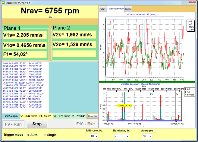
Sl. 7.10. Način rada mjerača vibracija. Provjera ukupne (V1s,V2s) i 1x (V1o,V2o) vibracije.
Ako je vrijednost ukupne vibracije V1s (V2s) približno jednaka amplitudi vibracije na frekvenciji rotacije (vibracija 1x) V1o (V2o), može se zaključiti da je nebalansiranost rotora glavni uzrok mehanizma vibracije. Ako je vrijednost ukupne vibracije V1s (V2s) značajno veća od komponente 1x vibracije V1o (V2o), preporučuje se provjeriti stanje mehanizma – stanje ležajeva, njegovo pričvršćivanje na osnovu, osigurati da nema kontakta između fiksnih dijelova i rotora tijekom rotacije, itd.
Također treba obratiti pažnju na stabilnost izmjerenih vrijednosti u načinu rada mjerača vibracija – amplituda i faza vibracije ne smiju varirati više od 10-15% tokom procesa mjerenja. U suprotnom, može se pretpostaviti da mehanizam radi u blizini rezonantnog područja. U tom slučaju, promijenite brzinu rotacije rotora, a ako to nije moguće – promijenite uslove postavljanja mašine na temelj (na primjer, privremeno postavljanje na opružne oslonce).
Za balansiranje rotora metoda koeficijenata utjecaja balansiranja (metoda 3 pokušaja) trebalo bi se koristiti.
Probna pokretanja se izvode kako bi se utvrdio uticaj probne mase na promjenu vibracija, te masa i mjesto (ugao) postavljanja korekcionih tegova.
Prvo odredite početnu vibraciju mehanizma (prvi start bez tegova), a zatim postavite probni teg na prvu ravninu i izvršite drugi start. Zatim uklonite probni teg iz prve ravnine, postavite ga u drugu ravninu i izvršite drugi start.
Program zatim izračunava i prikazuje na ekranu masu i lokaciju (ugao) postavljanja korekcionih tegova.
Kod balansiranja u jednoj ravnini (statički), drugi start nije potreban.
Probni teg se postavlja na proizvoljno mjesto na rotoru gdje je to pogodno, a zatim se stvarni radijus unosi u program postavki.
(Položajni radijus se koristi samo za izračunavanje količine neuravnoteženosti u gramima * mm)
Važno!
- Mjerenja treba provoditi pri konstantnoj brzini rotacije mehanizma!
- Korekcijski tegovi moraju biti instalirani na istom radijusu kao i probni tegovi!
Masa probnog tega se bira tako da nakon njegove instalacije faza (> 20-30°) i (20-30%) amplituda vibracija značajno promijeni. Ako su promjene premale, greška se znatno povećava u naknadnim proračunima. Pogodno je postaviti probnu masu na isto mjesto (isti ugao) kao i fazna oznaka.
Formula za izračunavanje mase probne težine
Mt = Mr × Ksupport × Kvibration / (Rt × (N/100)²)
Gdje:
- Mt — masa ispitne težine, g
- Mr – masa rotora, g
- Ksupport — koeficijent krutosti oslonca (1-5)
- Kvibration – koeficijent nivoa vibracije (0,5–2,5)
- Rt – radijus instalacije probne težine, cm
- N – brzina rotora, RPM
Koeficijent krutosti oslonca (Ksupport):
- 1.0 - Vrlo meki oslonci (gumeni prigušivači)
- 2.0-3.0 - Srednja krutost (standardni ležajevi)
- 4.0-5.0 - Kruti oslonci (masivna temeljna konstrukcija)
Koeficijent nivoa vibracije (Kvibration):
- 0.5 – Niska vibracija (do 5 mm/s)
- 1.0 – Normalna vibracija (5–10 mm/s)
- 1.5 – Povišena vibracija (10–20 mm/s)
- 2.0 - Visoka vibracija (20-40 mm/sec)
- 2.5 - Vrlo visoka vibracija (>40 mm/sec)
🔗 Koristite naš online kalkulator:
Kalkulator za ispitnu masu →⚠️ Važno!
Nakon svakog probnog rada probne mase se uklanjaju! Korekcijski tegovi se postavljaju pod uglom izračunatim od mjesta instalacije probnog tegova u smjeru rotacije rotora!
Objašnjenje izračunavanja ugla:
Ugao instalacije korekcijske mase je UVIJEK brojano od točke instalacije ispitne mase u smjeru rotacije rotora.
- Nulta točka (0°): Točno mjesto gdje ste instalirali ispitnu masu postaje vaša referentna točka (0 stepeni).
- Smjer: Izmjerite ugao u istom smjeru u kojem se rotor vrti.
Primjer: Ako se rotor vrti u smjeru kazaljke na satu, izmjerite ugao u smjeru kazaljke na satu od položaja ispitne mase. - Tumačenje: Ako program prikazuje ugao od 120°, morate instalirati korekcijsku masu 120 stepeni unaprijed od položaja ispitne mase u smjeru rotacije.
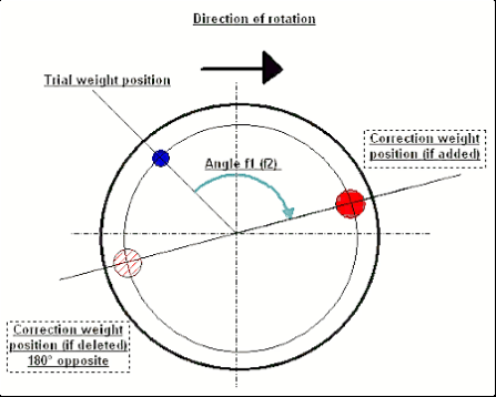
Sl. 7.11. Montaža korekcijskog tega.
Preporučeno!
Prije izvođenja dinamičkog balansiranja, preporučuje se provjeriti da statička neuravnoteženost nije previsoka. Za rotore sa horizontalnom osi, rotor se može ručno rotirati za ugao od 90 stepeni od trenutne pozicije. Ako je rotor statički neuravnotežen, rotirat će se u položaj ravnoteže. Nakon što rotor preuzme položaj ravnoteže, potrebno je postaviti teg za balansiranje u gornju tačku približno u srednjem dijelu dužine rotora. Težina tega treba biti odabrana na takav način da se rotor ne pomjera u bilo kojem položaju.
Ovakvo pred-balansiranje smanjit će količinu vibracija pri prvom pokretanju jako neuravnoteženog rotora.
Instalacija i montaža senzora
VSenzor vibracija mora biti instaliran na mašini na odabranoj tački mjerenja i spojen na ulaz X1 USB interfejsne jedinice.
Postoje dvije konfiguracije montaže:
- Magneti
- Navojni svornjaci M4
Optički tahometarski senzor treba spojiti na ulaz X3 USB interfejsne jedinice. Štaviše, za korištenje ovog senzora na površinu rotora treba nanijeti posebnu reflektujuću oznaku.
📏 Zahtjevi za instalaciju optičkog senzora
- ✓Udaljenost do površine rotora: 50-500 mm (ovisno o modelu senzora)
- ✓Širina refleksivne trake: Minimalno 1-1,5 cm (zavisi od brzine i radijusa)
- ✓Orijentacija: Okomito na površinu rotora
- ✓Montaža: Koristite magnetni stalak ili stezač za stabilno pozicioniranje
- ✓Izbjegavajte direktnu sunčevu svjetlost ili jaku vještačku rasvjetu na senzoru/traci
💡 Izračunavanje širine trake: Za optimalnu performansu, izračunajte širinu trake koristeći:
L ≥ (N × R)/30000 ≥ 1.0-1.5 cm
Gdje: L - širina trake (cm), N - brzina rotora (rpm), R - radijus trake (cm)
Detaljni zahtjevi za odabir mjesta senzora i njihovo pričvršćivanje na objekt pri balansiranju navedeni su u Prilogu 1.
7.4 Balansiranje u jednoj ravnini
Sl. 7.12. "Balansiranje u jednoj ravnini"
Arhiv balansiranja
Da biste počeli rad na programu u modusu "Balansiranje u jednoj ravni" modu, kliknite na dugme "F2-Jedna ravan" (ili pritisnite F2 na tipkovnici računara).
Zatim kliknite na dugme "F7 – Balansiranje" dugme, nakon čega će Arhiva balansiranja u jednoj ravni pojavit će se prozor u kojem će se sačuvati podaci o balansiranju (vidi Sl. 7.13).

Sl. 7.13 Prozor za odabir arhiva balansiranja u jednoj ravnini.
U ovom prozoru potrebno je unijeti podatke o nazivu rotora (Naziv rotora), mjesto instalacije rotora (Postavite), tolerancije za vibracije i preostalu neuravnoteženost (Tolerancija), datum mjerenja. Ovi podaci se čuvaju u bazi podataka. Također, kreira se mapa Arc###, gdje je ### broj arhive u kojoj će se sačuvati grafikoni, izvještajna datoteka, itd. Nakon završetka balansiranja, generirat će se izvještajna datoteka koju je moguće uređivati i štampati u ugrađenom uređivaču.
Nakon unosa potrebnih podataka, potrebno je kliknuti na “F10-OK" dugme, nakon čega će "Balansiranje u jednoj ravni" prozor biti otvoren (vidjeti Sl. 7.13)
Postavke balansiranja (1 ravan)
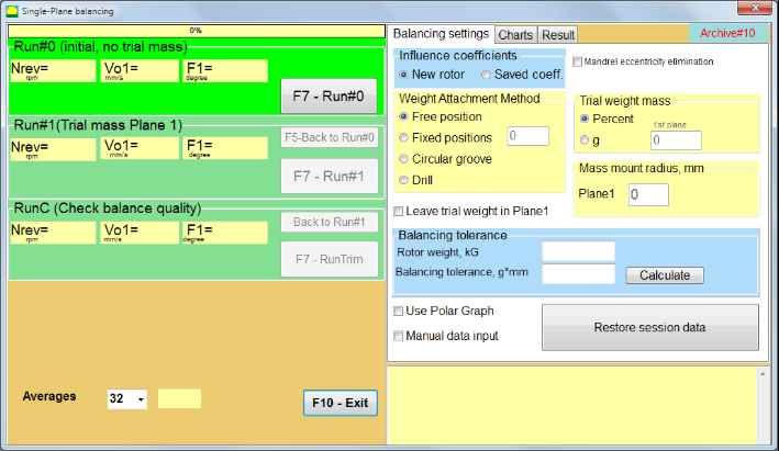
Sl. 7.14. Jedna ravan. Postavke balansiranja
Na lijevoj strani ovog prozora prikazani su podaci mjerenja vibracija i dugmadi za kontrolu mjerenja "Run # 0", "Run # 1", "RunTrim".
Na desnoj strani ovog prozora nalaze se tri kartice:
- Postavke balansiranja
- Grafikoni
- Rezultat
"Postavke balansiranja" kartica se koristi za unos postavki balansiranja:
- "Koeficijent uticaja" -
- "Novi rotor" – izbor balansiranja novog rotora, za koji ne postoje sačuvani koeficijenti balansiranja i potrebna su dva pokretanja za određivanje mase i ugla instalacije korekcijske težine.
- "Sačuvani koef." – izbor ponovnog balansiranja rotora, za koji postoje sačuvani koeficijenti balansiranja i potrebno je samo jedno pokretanje za određivanje mase i ugla instalacije korekcijske težine.
- "Masa probnog tega" -
- "Procenat" - korekcijska težina se izračunava kao procenat pokusne težine.
- "Gram" - poznata masa pokusne težine se unosi i masa korekcijske težine se izračunava u grama or in oz za imperijalni sistem.
⚠️ Pažnja! Ako je potrebno koristiti "Sačuvani koef.” Način rada za daljnji rad tokom početnog balansiranja, masa probnog tega mora biti unesena u gramima ili unčama, a ne u %. Vage su uključene u isporuku.
- "Metodu prikačivanja težine"
- "Slobodna pozicija" - težine se mogu instalirati na proizvoljna uglovna pozicija na obodu rotora.
- "Fiksna pozicija” – teg se može instalirati na fiksnim ugaonim pozicijama na rotoru, na primjer na lopaticama ili rupama (na primjer 12 rupa – 30 stepeni), itd. Broj fiksnih pozicija mora biti unesen u odgovarajuće polje. Nakon balansiranja, program će automatski podijeliti teg na dva dijela i naznačiti pozicije na kojima je potrebno postaviti dobijene mase.
- "Kružni žlijeb" – koristi se za uravnoteživanje brusnog toka U ovom slučaju koriste se 3 protuteže za eliminaciju neuravnoteženosti
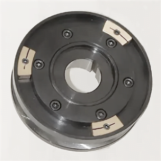
Sl. 7.17 Balansiranje brusnog kamena sa 3 protuteže
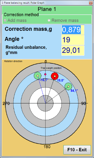
Sl. 7.18. Balansiranje brusnog kamena. Polarni grafikon.

Sl. 7.15. Kartica Rezultat. Fiksna pozicija montaže korekcijskog tegova.
Z1 i Z2 – pozicije instaliranih korekcijskih težina, izračunate od Z1 pozicije prema smjeru rotacije. Z1 je pozicija gdje je instalirana pokusna težina.
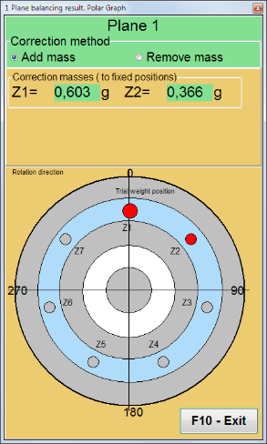
Sl. 7.16. Fiksne pozicije. Polarni dijagram.
- "Radijus montaže mase, mm" - "Ravnina1" - Radijus pokusne težine u 1. ravnini. Potreban je za izračunavanje veličine početne i rezidualne neuravnoteženosti kako bi se odredilo poštivanje dozvoljene vrijednosti rezidualne neuravnoteženosti nakon uravnoteživanja.
- "Ostavite probnu masu u Ravni1.” Obično se probni teg uklanja tokom procesa balansiranja. Ali u nekim slučajevima nije moguće ukloniti ga, tada je potrebno postaviti oznaku (kvačicu) da bi se masa probnog tega uzela u obzir u proračunima.
- "Ručni unos podataka” – koristi se za ručni unos vrijednosti vibracije i faze u odgovarajuća polja na lijevoj strani prozora i izračunavanje mase i ugla instalacije korekcijskog tega prilikom prebacivanja na “Rezultati" kartica
- Dugme "Vrati podatke sesije”. Tokom balansiranja, izmjereni podaci se čuvaju u fajlu session1.ini. Ako je proces mjerenja prekinut zbog zamrzavanja računara ili iz drugih razloga, klikom na ovo dugme možete vratiti izmjerene podatke i nastaviti balansiranje od trenutka prekida.
- Eliminacija ekscentričnosti trna (Indeksno balansiranje) Balansiranje sa dodatnim startom za eliminaciju uticaja ekscentričnosti mandrine (balansirne osovine). Montirajte rotor naizmjenično na 0° i 180° u odnosu na. Izmjerite neuravnoteženosti u oba položaja.
- Tolerancija balansiranja Unos ili izračunavanje tolerancija preostale neuravnoteženosti u g x mm (G-klase)
- Koristi polarni grafikon Koristi polarni grafikon za prikaz rezultata balansiranja
Balansiranje u 1 ravni. Novi rotor
Kao što je navedeno gore, "Novi rotor" uravnoteživanje zahtijeva dva pokusna prolaza i najmanje jedan prilagođavajući prolaz mašine za uravnoteživanje.
Pokretanje#0 (Početno pokretanje)
Nakon instalacije senzora na rotor za balansiranje i unosa parametara postavki, potrebno je uključiti rotaciju rotora i, kada dostigne radnu brzinu, pritisnuti dugme “Run#0" dugme za početak mjerenja. Kartica "Grafikoni" će se otvoriti u desnom panelu, gdje će biti prikazani oblik vala i spektar vibracija. U donjoj části kartice vodi se istorijska datoteka u kojoj se čuvaju rezultati svih pokretanja sa vremenskom referencom. Na disku se ova datoteka čuva u arhivskoj mapi pod imenom memo.txt
Pažnja!
Prije početka mjerenja, potrebno je pokrenuti rotaciju rotora mašine za balansiranje (Run#0) i uvjeriti se da je brzina rotora stabilna.
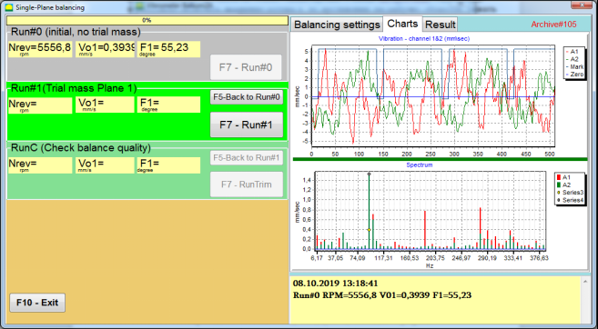
Slika 7.19. Balansiranje u jednoj ravnini. Početno pokretanje (Run#0). Kartica Grafikoni
Nakon završetka procesa mjerenja, u Run#0 dio u lijevoj paneli pojavljuju se rezultati mjerenja - brzina rotora (RPM), RMS (Vo1) i faza (F1) vibracija 1x.
"F5-Nazad na pokretanje#0” dugme (ili funkcijsku tipku F5) koristi se za povratak na odjeljak Run#0 i, po potrebi, ponovno mjerenje parametara vibracija.
Pokretanje#1 (Probna masa, ravan 1)
Prije početka mjerenja parametara vibracija u dijelu "Pokretanje#1 (Probna masa, ravan 1), pokusna težina bi trebala biti instalirana prema "Masa probnog tega" polje.
Cilj postavljanja probnog teg je procijeniti kako se vibracija rotora mijenja kada se poznata masa postavi na poznato mjesto (ugao). Probni teg mora promijeniti amplitudu vibracije za najmanje 30% niže ili više od početne amplitude ili promijeniti fazu za 30 stepeni ili više od početne faze.
Ako je potrebno koristiti "Sačuvani koef.” balansiranje za dalji rad, mjesto (ugao) instalacije probnog tega mora biti isto kao mjesto (ugao) reflektujuće oznake.
Ponovo uključite rotaciju rotora mašine za balansiranje i uvjerite se da je frekvencija rotacije stabilna. Zatim kliknite na “F7-Run#1" dugme (ili pritisnite F7 na tastaturi računara).
Nakon mjerenja u odgovarajućim poljima dijela "Pokretanje#1 (Probna masa, ravan 1)" dio, pojavljuju se rezultati mjerenja brzine rotora (RPM), kao i vrijednost RMS komponente (Vo1) i faze (F1) vibracija 1x.
U isto vrijeme, kartica "Rezultat" se otvara na desnoj strani prozora.
Ova kartica prikazuje rezultate izračunavanja mase i ugla korekcionog tega, koji se mora postaviti na rotor kako bi se kompenzovala neuravnoteženost.
Štaviše, u slučaju korištenja polarnog koordinatnog sistema, prikaz pokazuje vrijednost mase (M1) i ugao instalacije (f1) korekcijskog tega.
U slučaju da je "Fiksne pozicije" prikazaće se brojevi pozicija (Zi, Zj) i podijeljena masa probne težine.
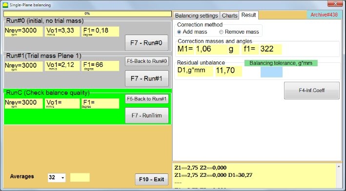
Slika 7.20. Balansiranje u jednoj ravnini. Run#1 i rezultat balansiranja.
Ako Polarni graf je označeno, prikazat će se polarni dijagram.
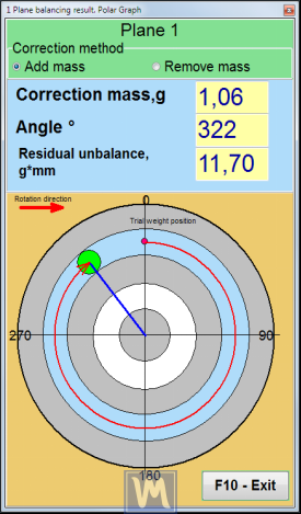
Slika 7.21. Rezultat balansiranja. Polarni grafikon.
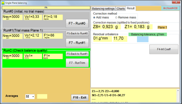
Slika 7.22. Rezultat balansiranja. Podijeljena masa (fiksne pozicije)
Također, ako "Polarni graf" bilo označeno, prikazat će se polarni grafikon.
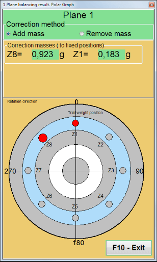
Slika 7.23. Masa podijeljena na fiksne pozicije. Polarni grafikon
⚠️ Pažnja!
- Nakon završetka procesa mjerenja pri drugom pokretanju („Pokretanje#1 (Probna masa, ravan 1)”) mašine za balansiranje, potrebno je zaustaviti rotaciju i ukloniti instalirani probni teg. Zatim instalirati (ili ukloniti) korekcijski teg na rotoru prema podacima na kartici Rezultat.
Ako probni teg nije uklonjen, potrebno je prebaciti se na “Postavke balansiranja" kartice i uključite polje za potvrdu u "Ostavite probni uteg u Ravni1". Zatim se vratite na karticu "Rezultat" kartici. Masa i ugao instalacije korekcijske težine se automatski ponovo izračunavaju.
- Kutni položaj korigovane težine vrši se od mjesta postavljanja ispitne težine. Smjer referencije kuta poklapa se sa smjerom rotacije rotora.
- U slučaju da je "Fiksna pozicija" - 1st pozicija (Z1), poklapa se sa mjestom postavljanja probnog tega. Smjer brojanja broja pozicije je u smjeru rotacije rotora.
- Po defaultu će se korigovana težina dodati na rotor. To je navedeno oznakom postavljenom u polju "Dodaj". Ako trebate ukloniti težinu (npr. bušenjem), morate postaviti oznaku u "Obriši" polju, nakon čega će se ugaona pozicija korekcijske težine automatski promijeniti za 180º.
Nakon postavljanja korekcionog tega na rotor za balansiranje u radnom prozoru, potrebno je izvršiti RunC (trim) i procijeniti efikasnost izvršenog balansiranja.
PokretanjeC (Provjera kvaliteta balansiranja)
⚠️ Pažnja! Prije početka mjerenja na RunC, potrebno je pokrenuti rotaciju rotora mašine i uvjeriti se da je ušla u radni režim (stabilna frekvencija rotacije).
Da biste izvršili mjerenje vibracija u "PokretanjeC (Provjera kvaliteta balansiranja)" odjeljenju, kliknite na dugme "F7 – RunTrim" (ili pritisnite tipku F7 na tastaturi).
Nakon uspješnog završetka procesa mjerenja, u "PokretanjeC (Provjera kvaliteta balansiranja)" odjeljenju u lijevoj ploči pojavljuju se rezultati mjerenja brzine rotora (RPM), kao i vrijednost RMS komponente (Vo1) i faza (F1) vibracije 1x.
U "Rezultat" kartici prikazuju se rezultati izračuna mase i ugla instalacije dodatne korekcijske težine.
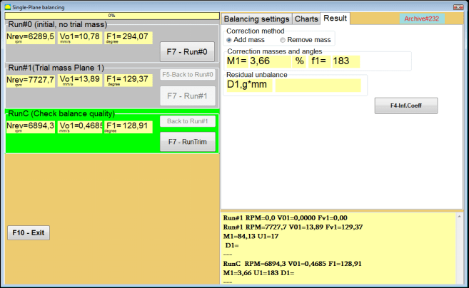
Slika 7.24. Balansiranje u jednoj ravnini. Izvršavanje RunTrim. Kartica Rezultati
Ova masa se može dodati korekcijskom tegu koji je već montiran na rotor kako bi se kompenzovala preostala neuravnoteženost. Pored toga, u donjem dijelu ovog prozora prikazuje se preostala neuravnoteženost rotora postignuta nakon balansiranja.
U slučaju kada količina preostalih vibracija i/ili preostale neuravnoteženosti balansiranih rotora zadovoljava zahtjeve tolerancije utvrđene u tehničkoj dokumentaciji, proces balansiranja se može završiti.
U suprotnom, proces balansiranja može se nastaviti. Ovo omogućava metodi sukcesivnih aproksimacija da ispravi moguće greške koje se mogu pojaviti tokom postavljanja (skidanja) korekcione mase na balansirani rotor.
Ako se proces balansiranja nastavlja na rotoru za balansiranje, potrebno je instalirati (ukloniti) dodatnu korekcijsku masu čiji su parametri navedeni u odjeljku “Korekcione mase i uglovi".
Koeficijenti uticaja (1 ravan)
"F4-Koef.uticaja" dugme u "Rezultat" kartica se koristi za pregled i pohranu u memoriju računala koeficijenata balansiranja rotora (Koeficijenti uticaja) izračunati iz rezultata kalibracionih pokusa.
Kada se pritisne, prozor "Koeficijenti uticaja (jedna ravan)" se pojavljuje na ekranu računala, u kojem se prikazuju koeficijenti balansiranja izračunati iz rezultata kalibracije (testnih) pokusa. Ako se tokom naknadnog balansiranja ove mašine pretpostavlja korištenje "Sačuvani koef.” način rada, ovi koeficijenti moraju biti sačuvani u memoriji računara.
Da biste to učinili, kliknite na dugme "F9 - Sačuvaj" i idite na drugu stranicu od "Arhiva koeficijenta uticaja. Jednoplanski."

Sl. 7.25. Koeficijenti balansiranja u 1. ravni
Zatim je potrebno unijeti naziv ove mašine u “Rotor" kolona i kliknite na "F2-Sačuvaj" dugme za čuvanje navedenih podataka na računaru.
Zatim se možete vratiti na prethodni prozor pritiskom na “F10-Izlaz" dugme (ili F10 tipka na računarskoj tastaturi).
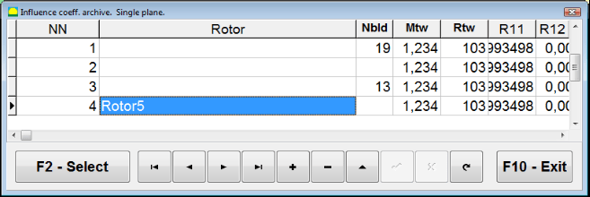
Sl. 7.26. "Arhiva koeficijenta uticaja. Jednoplanski."
Izvještaj o balansiranju
Nakon balansiranja svi podaci se čuvaju i kreira se izvještaj o balansiranju. Izvještaj možete pregledati i uređivati u ugrađenom uređivaču. U "Arhiva balansiranja u jednoj ravni" (Sl. 7.9) pritisnite dugme "F9 -Izvještaj" da biste pristupili editoru izveštaja o balansiranju.
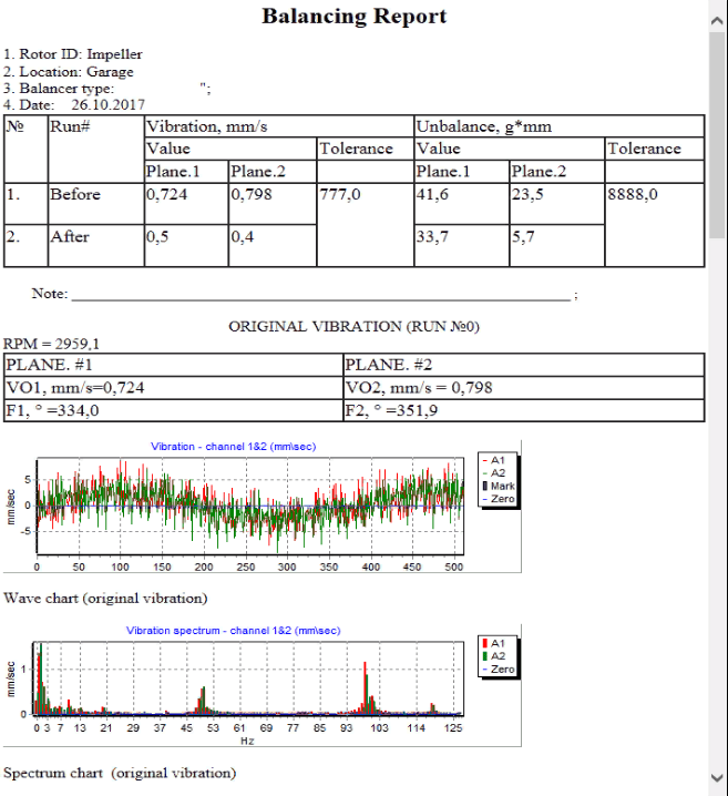
Sl. 7.27. Izveštaj o balansiranju.
Saved coeff. postupak balansiranja sa sačuvanim koeficijentima uticaja u 1 ravni.
Podešavanje mjernog sistema (unos početnih podataka).
Balansiranje sa sačuvanim koef. može se izvršiti na mašini za koju su koeficijenti balansiranja već određeni i uneseni u memoriju računara.
⚠️ Pažnja! Prilikom balansiranja sa sačuvanim koeficijentima, mjerni senzor vibracija i senzor faznog ugla moraju biti instalirani na isti način kao i tokom početnog balansiranja.
Unos početnih podataka za Balansiranje sa sačuvanim koef. (kao u slučaju primarnog("Novi rotor") balansiranja) počinje u "Balansiranje u jednoj ravnini. Postavke balansiranja.".
U ovom slučaju, u "Koeficijenti uticaja" sekciji, izaberite "Sačuvani koef" stavku. U ovom slučaju, druga stranica "Arhiva koef. uticaja. Jedna ravan.", koja čuva arhivu sačuvanih koeficijenata balansiranja.
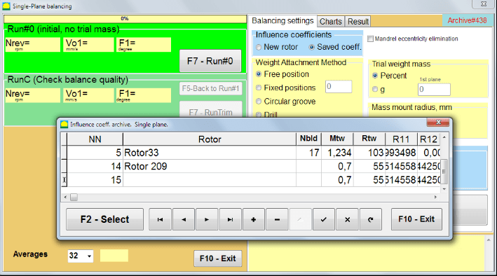
Sl. 7.28. Balansiranje sa sačuvanim koeficijentima uticaja u 1 ravni
Krećući se kroz tabelu ove arhive pomoću "►" ili "◄" kontrolnih dugmadi, možete izabrati željeni zapis sa koeficijentima balansiranja mašine od interesa. Zatim, da biste koristili ove podatke u trenutnim merenjima, pritisnite "F2 – Odaberi" dugme.
Nakon toga, sadržaj svih ostalih prozora “Balansiranje u jednoj ravnini. Postavke balansiranja." se popunjavaju automatski.
Nakon završetka unosa početnih podataka, možete početi sa mjerenjem.
Merenja tokom balansiranja sa sačuvanim koeficijentima uticaja
Balansiranje sa sačuvanim koeficijentima uticaja zahtijeva samo jedan početni radni ciklus i najmanje jedan probni radni ciklus mašine za balansiranje.
⚠️ Pažnja! Prije početka mjerenja, potrebno je uključiti rotaciju rotora i provjeriti da li je frekvencija rotacije stabilna.
Da biste izvršili merenje parametara vibracija u "Pokretanje#0 (Početno, bez probne mase)" sekciji, pritisnite "F7 – Run#0" (ili pritisnite F7 tipku na računarskoj tastaturi).
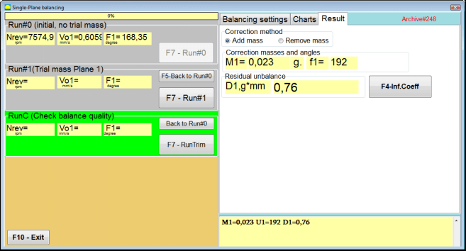
Sl. 7.29. Balansiranje sa sačuvanim koeficijentima uticaja u jednoj ravni. Rezultati nakon jednog radnog ciklusa.
U odgovarajućim poljima "Run#0" odjeljka pojavljuju se rezultati mjerenja brzine rotora (RPM), vrijednost RMS komponente (Vo1) i faze (F1) vibracije 1x.
U isto vrijeme, kartica "Rezultat” prikazuje rezultate izračunavanja mase i ugla korekcijskog tega koji se mora postaviti na rotor da bi se kompenzovala neuravnoteženost.
Štoviše, u slučaju korištenja polarnog koordinatnog sustava, prikaz pokazuje vrijednosti mase i uglove instalacije korekcijskih utega.
U slučaju raspodjele korekcionog tega na fiksne pozicije, prikazuju se brojevi pozicija rotora za balansiranje i masa tegova koji se moraju instalirati na njih.
Dalje, proces balansiranja se izvodi u skladu sa preporukama navedenim u odjeljku 7.4.2. za primarno balansiranje.
Eliminacija ekscentričnosti trna (Indeksno balansiranje)
Ako je tokom balansiranja rotor instaliran na cilindričnom trnu, ekscentričnost trna može unijeti dodatnu grešku. Da bi se ova greška eliminisala, rotor treba okrenuti na trnu za 180 stepeni i izvršiti dodatni radni ciklus. Ovo se naziva indeksno balansiranje.
Za izvršenje indeksnog balansiranja, u programu Balanset-1A je predviđena posebna opcija. Kada je označeno Eliminacija ekscentriciteta trna, u prozoru za balansiranje se pojavljuje dodatna sekcija RunEcc.

Sl. 7.30. Radni prozor za indeksno balansiranje.
Nakon pokretanja Run # 1 (Probna masa Ravan 1), pojavit će se prozor
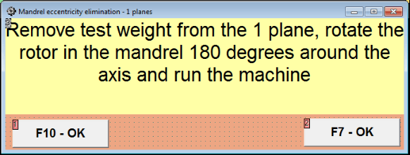
Sl. 7.31 Prozor upozorenja indeksnog balansiranja.
Nakon instalacije rotora sa okretom od 180°, potrebno je izvršiti RunEcc. Program će automatski izračunati stvarnu neuravnoteženost rotora bez uticaja ekscentričnosti mandrine.
7.5 Balansiranje u dvije ravnine
Prije početka rada u Balansiranje u dvije ravni režimu, neophodno je instalirati senzore vibracija na kućište mašine na odabranim mjernim mjestima i povezati ih sa ulazima X1 i X2 mjerne jedinice, redom.
Optički senzor faznog ugla mora biti povezan sa ulazom X3 mjerne jedinice. Pored toga, za korištenje ovog senzora, reflektujuća traka se mora zalijepiti na dostupnu površinu rotora mašine za balansiranje.
Detaljni zahtjevi za odabir mjesta instalacije senzora i njihovo montažiranje na objektu tokom balansiranja navedeni su u Prilogu 1.
Rad na programu u "Balansiranje u dvije ravni" režimu počinje iz Glavnog prozora programa.
Kliknite na "F3-Dvije ravni" tipka (ili pritisnite F3 na računalnoj tipkovnici).
Nadalje, kliknite na dugme “F7 – Balancing”, nakon čega će se na ekranu računara prikazati radni prozor (vidi Sl. 7.13) – izbor arhive za spremanje podataka pri balansiranju u dvije ravnine.
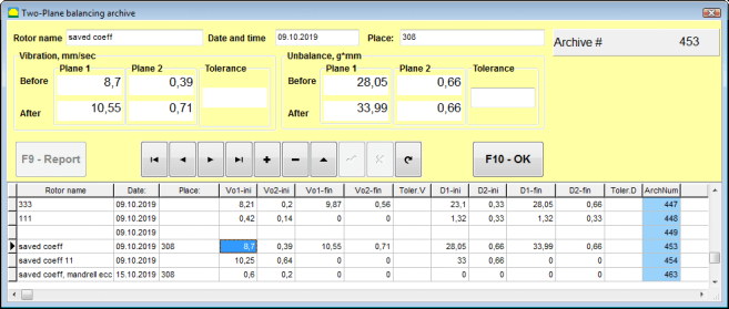
Sl. 7.32 Prozor arhive balansiranja u dvije ravni.
U ovom prozoru potrebno je unijeti podatke o balansiranom rotoru. Nakon pritiska na “F10-OK" tipka, pojavit će se prozor balansiranja.
Postavke balansiranja (2 ravni)
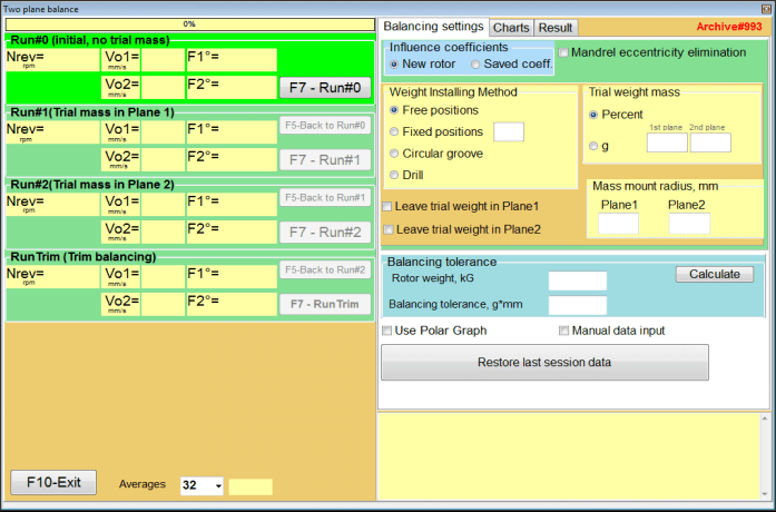
Sl. 7.33. Prozor balansiranja u dvije ravnine.
Na desnoj strani prozora nalazi se "Postavke balansiranja" kartica za unos postavki prije balansiranja.
- Koeficijenti uticaja - Balansiranje novog rotora ili balansiranje korištenjem sačuvanih koeficijenata uticaja (koeficijenti balansiranja)
- Eliminacija ekscentriciteta trna - Balansiranje s dodatnim pokretanjem za eliminaciju utjecaja ekscentričnosti mandrelja
- Način pričvršćivanja tega Instalacija korekcijskih tegova na proizvoljnom mjestu na obodu rotora ili na fiksnoj poziciji. Proračun bušenja pri uklanjanju mase.
- "Slobodna pozicija" - težine se mogu instalirati na proizvoljna uglovna pozicija na obodu rotora.
- "Fiksna pozicija” – teg se može instalirati na fiksnim ugaonim pozicijama na rotoru, na primjer na lopaticama ili rupama (na primjer 12 rupa – 30 stepeni), itd. Broj fiksnih pozicija mora biti unesen u odgovarajuće polje. Nakon balansiranja, program će automatski podijeliti teg na dva dijela i naznačiti pozicije na kojima je potrebno postaviti dobijene mase.
- Masa probnog tega - Probni uteg
- Ostavite probnu masu u ravnini 1 / ravnini 2 - Uklonite ili ostavite pokusni uteg pri balansiranju.
- Radijus montaže mase, mm - Radijus montaže pokusnih i korekcijskih utega
- Tolerancija balansiranja - Unos ili izračun tolerancija preostalog debalansa u g-mm
- Koristi polarni grafikon - Koristi polarni graf za prikaz rezultata balansiranja
- Ručni unos podataka - Ručni unos podataka za izračunavanje utega balansiranja
- Vrati podatke posljednje sesije - Oporavak podataka mjerenja iz zadnje sesije u slučaju neuspjeha nastavka balansiranja.
Balansiranje u 2 ravni. Novi rotor
Podešavanje mjernog sistema (unos početnih podataka).
Unos početnih podataka za Balansiranje novog rotora u stavki "Balansiranje u dvije ravnine. Postavke".
U ovom slučaju, u "Koeficijenti uticaja" sekciji, izaberite "Novi rotor".
Dalje, u odjeljku "Masa probnog tega", morate odabrati mjernu jedinicu mase pokusnog utega - "Gram" ili "Procenat".
Pri odabiru mjerne jedinice "Procenat”, svi daljnji proračuni mase korekcijskog tega vršit će se u procentima u odnosu na masu probnog tega.
Prilikom izbora "Gram" mjernu jedinicu, svi daljnji proračuni mase korekcijske težine vršit će se u gramima. Zatim unesite u prozore koji se nalaze desno od natpisa "Gram" masa pokusnih težina koje će biti postavljene na rotor.
⚠️ Pažnja! Ako je potrebno koristiti "Sačuvani koef.” način rada za dalji rad tokom početnog balansiranja, masa probnih tegova mora biti unesena u grama.
Zatim odaberite "Način pričvršćivanja tega" - "Obim" ili "Fiksna pozicija".
Ako odaberete "Fiksna pozicija", morate uneti broj pozicija.
Proračun tolerancije za preostalu neuravnoteženost (Tolerancija balansiranja)
Dozvoljeno odstupanje za preostalu nebalansu (Tolerancija balansiranja) može se izračunati u skladu sa postupkom opisanim u ISO 1940 Vibrations. Zahtevi za kvalitet balansa rotora u stalnom (krutom) stanju. Deo 1. Specifikacija i provera tolerancija balansa.

Slika 7.34. Prozor za izračun tolerancije balansiranja
Početno pokretanje (Pokretanje#0)
Pri balansiranju u dvije ravni u "Novi rotor" načinu, balansiranje zahtijeva tri kalibracijska prolaza i najmanje jedan testni prolaz balansne mašine.
Merenje vibracija pri prvom pokretanju mašine vrši se u "Balansiranje u dvije ravni" radnoj prozoru u "Run#0" odjeljak.
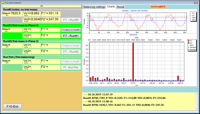
Sl. 7.35. Rezultati merenja pri balansiranju u dvije ravni nakon početnog pokretanja.
⚠️ Pažnja! Prije početka mjerenja, potrebno je uključiti rotaciju rotora mašine za balansiranje (prvo pokretanje) i uvjeriti se da je ušao u radni režim sa stabilnom brzinom.
Za mjerenje parametara vibracija u Run#0 sekcija, kliknite na "F7 – Run#0" dugme (ili pritisnite taster F7 na računarskoj tastaturi)
Rezultati mjerenja brzine rotora (RPM), vrijednost RMS (VО1, VО2) i faze (F1, F2) vibracije 1x pojavljuju se u odgovarajućim prozorima Run#0 odjeljak.
Pokretanje#1.Probna masa u ravni 1
Pre nego što počnete sa merenjem parametara vibracija u "Pokretanje#1.Probna masa u ravni 1" odjeljku, trebate zaustaviti rotaciju rotora mašine za balansiranje i instalirati na njega probnu težinu, masu odabranu u "Masa probnog tega" odjeljak.
⚠️ Pažnja!
- Pitanje odabira mase probnih tegova i mjesta njihove instalacije na rotoru mašine za balansiranje detaljno je razmotreno u Dodatku 1.
- Ako je potrebno koristiti Sačuvani koef. režimu u budućem radu, mjesto za postavljanje probnog tega mora se nužno poklapati sa mjestom za postavljanje oznake koja se koristi za očitavanje faznog ugla.
Nakon toga potrebno je ponovo uključiti rotaciju rotora balansne mašine i uvjeriti se da je ušao u radni način.
Za merenje parametara vibracija u "Pokretanje # 1.Probna masa u ravni 1" odjeljenju, kliknite na dugme "F7 – Run#1" dugme (ili pritisnite F7 na tastaturi računara).
Uspešnom završetku procesa merenja, vraćeni ste na kartici sa rezultatima merenja.
U ovom slučaju, u odgovarajućim prozorima "Pokretanje#1. Probna masa u ravni 1" odjeljku pojavljuju se rezultati mjerenja brzine rotora (RPM), kao i vrijednost komponenti RMS (Vо1, Vо2) i faza (F1, F2) vibracije 1x.
"Pokus br. 2.Pokusna masa u Ravni 2"
Pre nego što počnete sa merenjem parametara vibracija u sekciji "Pokretanje # 2.Probna masa u ravni 2", morate izvršiti sledeće korake:
- zaustaviti rotaciju rotora mašine za balansiranje;
- ukloniti pokušajnu masu instaliranu u ravnini 1;
- instalirati pokušajnu masu u ravnini 2, masa odabrana u odjeljku "Masa probnog tega".
Nakon toga uključite rotaciju rotora balansne mašine i uvjerite se da je ušao u radnu brzinu.
Za početak mjerenja vibracija u "Pokretanje # 2.Probna masa u ravni 2" odjeljenju, kliknite na dugme "F7 – Run # 2" dugme (ili pritisnite tipku F7 na tipkovnici računara). Tada će se "Rezultat" otvara se kartica.
U slučaju korištenja Način pričvršćivanja tega" - "Slobodne pozicije, displej prikazuje vrijednosti masa (M1, M2) i kutove instalacije (f1, f2) korekcijskih utega.
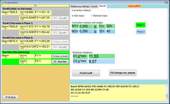
Slika 7.36. Rezultati izračuna korekcijskih tegova – slobodan položaj
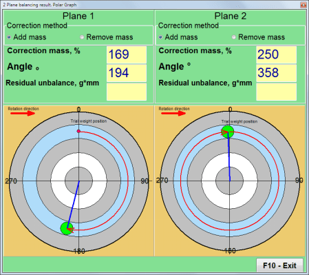
Sl. 7.37. Rezultati proračuna korekcijskih težina – slobodna pozicija. Polarni dijagram
U slučaju korištenja metode pričvršćivanja tegova" – "Fiksne pozicije

Sl. 7.38. Rezultati proračuna korekcijskih utega – fiksna pozicija.
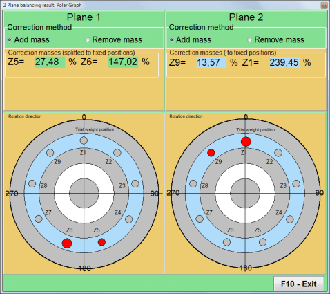
Slika 7.39. Rezultati proračuna korektivnih težina – fiksna pozicija. Polarni dijagram.
U slučaju korištenja metode pričvršćivanja utega" – "Kružni žlijeb"
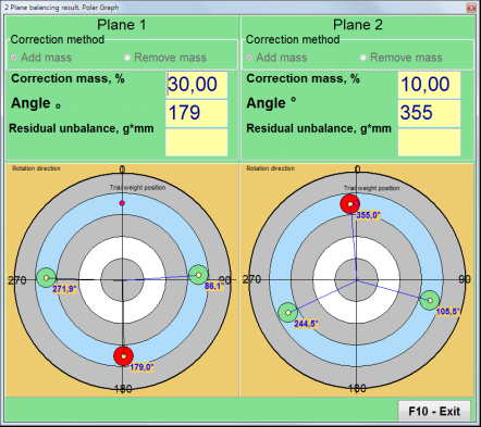
Sl. 7.40. Rezultati proračuna korekcijskih utega – Kružni žlijeb.
⚠️ Pažnja!
- Nakon dovršetka procesa mjerenja na RUN#2 balansne mašine, zaustavite rotaciju rotora i uklonite prethodno postavljeni probni teg. Tada možete postaviti (ili ukloniti) korekcijske tegove.
- Kutna pozicija korekcijskih utega u polarnom koordinatnom sustavu računa se od mjesta instalacije pokušajne mase u smjeru vrtnje rotora.
- U slučaju da je "Fiksna pozicija" - 1st pozicija (Z1), poklapa se sa mjestom postavljanja probnog tega. Smjer brojanja broja pozicije je u smjeru rotacije rotora.
- Po defaultu će se korigovana težina dodati na rotor. To je navedeno oznakom postavljenom u polju "Dodaj". Ako trebate ukloniti težinu (npr. bušenjem), morate postaviti oznaku u "Obriši" polju, nakon čega će se ugaona pozicija korekcijske težine automatski promijeniti za 180º.
PokretanjeC (Dotjerivanje)
Nakon postavljanja korekcijskog tega na rotor balansne mašine potrebno je izvršiti RunC (dotjerivanje) i procijeniti efikasnost izvršenog balansiranja.
⚠️ Pažnja! Prije početka mjerenja na probnom pokretanju, potrebno je uključiti rotaciju rotora mašine i uvjeriti se da je ušao u radni režim sa stabilnom brzinom.
Za mjerenje parametara vibracija u odjeljku RunTrim (Provjera kvalitete uravnoteženja), kliknite na "F7 – RunTrim" dugme (ili pritisnite F7 na tastaturi računara).
Rezultati mjerenja frekvencije rotacije rotora (RPM), kao i vrijednost RMS komponente (Vо1) i faze (F1) vibracija 1x biće prikazani.
"Rezultat" kartica se pojavljuje na desnoj strani radnog prozora s tablicom rezultata mjerenja, koja prikazuje rezultate proračuna parametara dodatnih korekcijskih utega.
Ovi tegovi se mogu dodati korekcijskim tegovima koji su već postavljeni na rotor kako bi se kompenzovala preostala neuravnoteženost.
Pored toga, u donjem dijelu ovog prozora prikazuje se preostala neuravnoteženost rotora postignuta nakon balansiranja.
U slučaju kada vrijednosti rezidualne vibracije i/ili rezidualnog neuravnoteženja uravnoteženog rotora zadovoljavaju tolerancijske zahtjeve uspostavljene u tehničkoj dokumentaciji, proces uravnoteženja može biti završen.
U suprotnom, proces balansiranja može se nastaviti. Ovo omogućava metodi sukcesivnih aproksimacija da ispravi moguće greške koje se mogu pojaviti tokom postavljanja (skidanja) korekcione mase na balansirani rotor.
Ako se proces balansiranja nastavlja na rotoru za balansiranje, potrebno je instalirati (ukloniti) dodatnu korekcijsku masu čiji su parametri navedeni u prozoru “Result”.
U "Rezultat" prozor postoje dva kontrolna dugmeta koja se mogu koristiti - "F4-Koef.uticaja", "F5 – Promjena korekcionih ravni".
Koeficijenti uticaja (2 ravni)
"F4-Koef.uticaja" dugme (ili tipka funkcije F4 na tipkovnici računara) koristi se za pregled i spremanje koeficijenata uravnoteženja rotora u memoriji računara, izračunatih iz rezultata dva kalibracijska pokretanja.
Kada se pritisne, prozor "Koeficijenti uticaja (dvije ravni)" radni prozor se pojavljuje na zaslonu računala, u kojem se prikazuju koeficijenti uravnoteženja izračunati na osnovu rezultata prva tri kalibracijiskog pokretanja.

Slika 7.41. Radni prozor sa koeficijentima balansiranja u 2 ravnine.
Ubuduće, kada se za balansiranje ove vrste mašine predviđa korištenje “Sačuvani koef." način rada i koeficijenti uravnoteženja pohranjeni u memoriji računara.
Za spremanje koeficijenata, kliknite na "F9 – Sačuvaj" dugme i idite na "Arhiva koeficijenata uticaja (2 ravni)" prozore (vidi sl. 7.42)
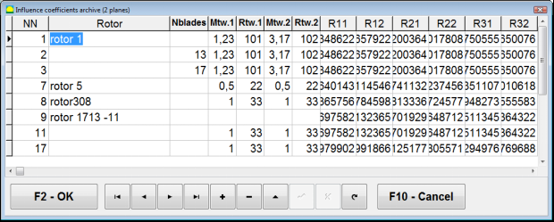
Slika 7.42. Druga stranica radnog prozora sa koeficijentima balansiranja u 2 ravnine.
Promjena korekcionih ravni
"F5 – Promjena korekcionih ravni" gumb se koristi kada trebate promijeniti poziciju ravnina korekcije, kada je potrebno ponovno izračunati mase i kutove instalacije korekcijskih utega.
Ovaj način je prvenstveno koristan pri balansiranju rotora složenog oblika (na primjer, radilica).
Kada se pritisne ovaj gumb, radni prozor "Ponovni izračun mase i ugla korekcijskih tegova na druge korekcijske ravnine" je prikazan na prikazu računala.
U ovom radnom prozoru treba odabrati jednu od 4 moguće opcije klikom na odgovarajuću sliku.
Originalne korekcijske ravni (Н1 i Н2) na Sl. 7.29 označene su zelenom bojom, a nove (K1 i K2), za koje se vrši ponovni proračun, crvenom bojom.
Zatim, u kartici "Podaci proračuna" odjeljak, unesite tražene podatke, uključujući:
- udaljenost između odgovarajućih ravnina korekcije (a, b, c);
- nove vrijednosti polumjera instalacije korekcijskih utega na rotoru (R1', R2').
Nakon unosa podataka, morate pritisnuti gumb "F9 – Izračunaj"
Rezultati proračuna (mase M1, M2 i uglovi instalacije korekcijskih tegova f1, f2) prikazuju se u odgovarajućem odjeljku ovog radnog prozora (vidi Sl. 7.42).
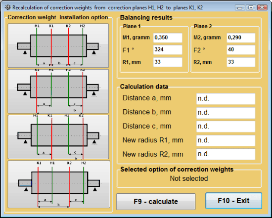
Slika 7.43 Promjena ravnina korekcije. Ponovno izračunavanje korekcijske mase i kuta za druge ravnine korekcije.
Sačuvani koef. balansiranja u 2 ravnine
Balansiranje sa sačuvanim koef. može se izvršiti na mašini za koju su koeficijenti balansiranja već određeni i sačuvani u memoriji računara.
⚠️ Pažnja! Prilikom ponovnog balansiranja, senzori vibracija i senzor faznog ugla moraju biti instalirani na isti način kao i tokom početnog balansiranja.
Unos početnih podataka za ponovno balansiranje počinje u "Balansiranje u 2 ravnine. Postavke balansiranja".
U ovom slučaju, u "Koeficijenti uticaja" sekciji, izaberite "Sačuvani koef." stavka. U tom slučaju, prozor "Arhiva koeficijenata uticaja (2 ravni)" će se pojaviti, u kojem se pohranjuje arhiva prethodno određenih koeficijenata balansiranja.
Krećući se kroz tabelu ove arhive pomoću "►" ili "◄" kontrolnih dugmadi, možete izabrati željeni zapis sa koeficijentima balansiranja mašine od interesa. Zatim, da biste koristili ove podatke u trenutnim merenjima, pritisnite "F2 – OK” dugme i vratite se na prethodni radni prozor.
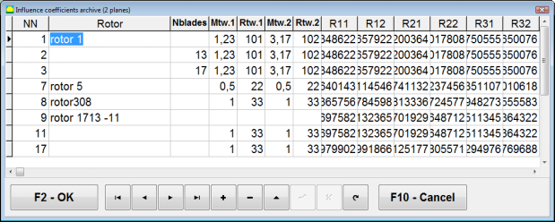
Sl. 7.44. Druga stranica radnog prozora sa koeficijentima balansiranja u 2 ravnine.
Nakon toga, sadržaj svih ostalih prozora “Balansiranje u 2 rav. Početni podaci" se popunjava automatski.
Balansiranje sa sačuvanim koef.
"Sačuvani koef." balansiranje zahtijeva samo jedan start podešavanja i najmanje jedan testni start mašine za balansiranje.
Mjerenje vibracija na početku podešavanja (Run # 0") stroja se provodi u "Balansiranje u 2 ravni" radnom prozoru s tablicom rezultata balansiranja u Run # 0 odjeljak.
⚠️ Pažnja! Prije početka mjerenja, potrebno je uključiti rotaciju rotora mašine za balansiranje i uvjeriti se da je ušao u radni režim sa stabilnom brzinom.
Za mjerenje parametara vibracija u Run # 0 odjeljak, kliknite na "F7 – Run#0" dugme (ili pritisnite F7 na tastaturi računara).
Rezultati mjerenja brzine rotora (RPM), kao i vrijednosti komponenti RMS (VО1, VО2) i faza (F1, F2) vibracija 1x pojavljuju se u odgovarajućim poljima Run # 0 odjeljak.
U isto vrijeme, kartica "Rezultat" kartica se otvara, koja prikazuje rezultate izračunavanja parametara korekcijskih utega koji moraju biti instalirani na rotoru kako bi se kompenzirala njegova neuravnoteženost.
Štoviše, u slučaju korištenja polarnog koordinatnog sustava, prikaz pokazuje vrijednosti mase i kutove instalacije korekcijskih utega.
U slučaju dekompozicije korekcijskih tegova na lopaticama, prikazuju se brojevi lopatica balansiranog rotora i masa tegova koji moraju biti instalirani na njima.
Dalje, proces balansiranja se izvodi u skladu sa preporukama navedenim u odjeljku 7.6.1.2. za primarno balansiranje.
⚠️ Pažnja!
- Nakon završetka procesa mjerenja nakon drugog starta balansirane mašine, zaustavite rotaciju njenog rotora i uklonite prethodno postavljeni probni teg. Tek tada možete početi sa instaliranjem (ili uklanjanjem) korekcijskih tegova na rotoru.
- Brojanje ugaone pozicije mjesta dodavanja (ili uklanjanja) korekcijskog tega sa rotora vrši se od mjesta postavljanja probnog tega u polarnom koordinatnom sistemu. Smjer brojanja se poklapa sa smjerom rotacije rotora.
- U slučaju balansiranja na lopaticama – lopatica uravnoteženog rotora, označena kao pozicija 1, poklapa se sa mjestom instalacije pokusne težine. Smjer referentnog broja lopatice prikazane na ekranu računara izvršava se u smjeru rotacije rotora.
- U ovoj verziji programa pretpostavlja se po zadanoj vrijednosti da će se korekcijska težina dodati na rotor. Oznaka postavljena u polju "Dodavanje" to potvrđuje. U slučaju korekcije neuravnoteženosti uklanjanjem težine (na primjer bušenjem) potrebno je postaviti oznaku u polju "Uklanjanje" tada će se kutna pozicija korekcijske težine automatski promijeniti za 180º.
Eliminacija ekscentričnosti vretena (Indeksno balansiranje) - Dvije ravnine
Ako je tokom balansiranja rotor instaliran na cilindričnom trnu, ekscentričnost trna može unijeti dodatnu grešku. Da bi se ova greška eliminisala, rotor treba okrenuti na trnu za 180 stepeni i izvršiti dodatni radni ciklus. Ovo se naziva indeksno balansiranje.
Za izvršenje indeksnog balansiranja, u programu Balanset-1A je predviđena posebna opcija. Kada je označeno Eliminacija ekscentriciteta trna, u prozoru za balansiranje se pojavljuje dodatna sekcija RunEcc.
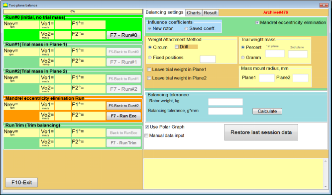
Sl. 7.45. Radni prozor za indeksno balansiranje.
Nakon pokretanja Run # 2 (Probna masa Ravnina 2), pojaviće se prozor
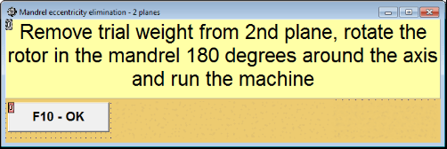
Sl. 7.46. Prozori upozorenja
Nakon instalacije rotora sa okretom od 180°, potrebno je izvršiti RunEcc. Program će automatski izračunati stvarnu neuravnoteženost rotora bez uticaja ekscentričnosti mandrine.
7.6 Režim grafika
Rad u režimu "Grafika" počinje iz početnog prozora (vidi sl. 7.1) pritiskom na "F8 – Grafika". Tada se otvara prozor "Mjerenje vibracija na dva kanala. Grafika" (vidi sl. 7.19).

Sl. 7.47. Radni prozor "Mjerenje vibracija na dva kanala. Grafika".
Tokom rada u ovom režimu moguće je iscrtati četiri verzije grafikona vibracija.
Prva verzija omogućava dobijanje vremenske funkcije ukupne vibracije (brzine vibracije) na prvom i drugom mjernom kanalu.
Druga verzija vam omogućava da dobijete grafike vibracija (brzine vibracije), koje se javljaju na frekvenciji rotacije i njenim višim harmonijskim komponentama.
Ovi grafikoni su dobijeni kao rezultat sinhronog filtriranja ukupne funkcije vremena vibracije.
Treća verzija daje grafikone vibracija sa rezultatima harmonijske analize.
Četvrta verzija omogućava dobijanje grafikona vibracija sa rezultatima analize spektra.
Grafici ukupne vibracije
Za crtanje grafa ukupne vibracije u radnom prozoru "Mjerenje vibracija na dva kanala. Grafikoni" potrebno je odabrati režim rada "ukupne vibracije” klikom na odgovarajuće dugme. Zatim podesite mjerenje vibracije u okviru „Trajanje, u sekundama“, klikom na dugme «▼» i sa padajuće liste izaberite željeno trajanje procesa merenja, koje može biti jednako 1, 5, 10 , 15 ili 20 sekundi;
Kada je spreman pritisnite (kliknite) dugme "F9-Mjerenje" tada počinje proces mjerenja vibracija istovremeno na dva kanala.
Nakon završetka procesa mjerenja u radnom prozoru se pojavljuju grafikoni vremenske funkcije ukupne vibracije prvog (crvenog) i drugog (zeleno) kanala (vidi. Sl. 7.47).
Na ovim grafikonima vrijeme je iscrtano na X-osi, a amplituda brzine vibracije (mm/sec) je iscrtana na Y-osi.
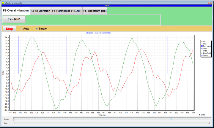
Sl. 7.48. Radni prozor za prikaz vremenske funkcije grafika ukupne vibracije
Na ovim grafikonima postoje i oznake (plave boje) koje povezuju grafikone ukupne vibracije sa frekvencijom rotacije rotora. Osim toga, svaka oznaka označava početak (kraj) sljedećeg okretaja rotora.
Za promjenu skale grafikona na X-osi klizač, usmjeren strelicom na sl. 7.20, može se koristiti.
Grafici 1x vibracije
Za crtanje grafa 1x vibracije u radnom prozoru "Mjerenje vibracija na dva kanala. Grafikoni" potrebno je odabrati režim rada "1x vibracija" klikom na odgovarajuće dugme.
Tada se pojavljuje radni prozor "1x vibracija".
Pritisnite (kliknite) "F9-Mjerenje" tada počinje proces mjerenja vibracija istovremeno na dva kanala.
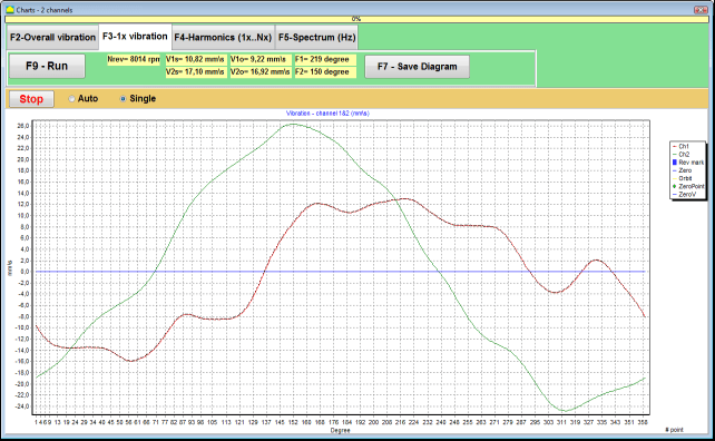
Sl. 7.49. Radni prozor za prikaz grafika 1x vibracije.
Nakon završetka procesa mjerenja i matematičkog izračunavanja rezultata (sinhrono filtriranje vremenske funkcije ukupne vibracije) na displeju u glavnom prozoru u periodu jednakom jedan okret rotora pojavljuju se grafikoni 1x vibracija na dva kanala.
U ovom slučaju, grafikon za prvi kanal je prikazan crvenom, a za drugi kanal zelenom bojom. Na ovim dijagramima ugao obrtaja rotora je iscrtan (od oznake do oznake) na X-osi, a amplituda brzine vibracije (mm/sec) na Y-osi.
Osim toga, u gornjem dijelu radnog prozora (desno od dugmeta “F9 – Mjeri") numeričke vrijednosti mjerenja vibracija oba kanala, slične onima koje dobijamo u "Mjerač vibracija" režim, se prikazuju.
Posebno: RMS vrijednost ukupne vibracije (V1s, V2s), veličina RMS (V1o, V2o) i faza (Fi, Fj) od 1x vibracije i brzine rotora (Nrev).
Dijagrami vibracija s rezultatima harmonijske analize
Da biste nacrtali dijagram s rezultatima harmonijske analize u radnom prozoru "Mjerenje vibracija na dva kanala. Grafikoni" potrebno je odabrati režim rada "Harmonijska analiza" klikom na odgovarajuće dugme.
Zatim se pojavljuje operativni prozor za simultani izlaz dijagrama privremene funkcije i spektra aspekata harmoničnih vibracija čiji je period jednak ili višestruki frekvenciji rotacije rotora (vidi sliku 7.49)
Pažnja!
Pri radu u ovom režimu potrebno je koristiti senzor faznog ugla koji sinhronizira proces mjerenja sa frekvencijom rotora mašine na koju je senzor podešen.
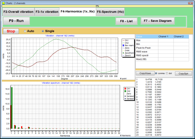
Sl. 7.50. Radni prozor harmonika vibracija 1x.
Kada je spreman pritisnite (kliknite) dugme "F9-Mjerenje" tada počinje proces mjerenja vibracija istovremeno na dva kanala.
Nakon završetka mjernog procesa u radnom prozoru pojavljuju se dijagrami vremenske funkcije (gornji dijagram) i harmonika vibracija 1x (donji dijagram).
Broj harmonijskih komponenti je iscrtan na X-osi, a RMS brzine vibracije (mm/sec) je prikazan na Y-osi.
Dijagrami vremenske domene vibracija i spektra
Da biste nacrtali dijagram spektra, koristite "F5-Spektar" kartici:
Tada se pojavljuje radni prozor za istovremeni prikaz dijagrama valnog oblika i spektra vibracija.

Sl. 7.51. Radni prozor za prikaz spektra vibracija.
Kada je spreman pritisnite (kliknite) dugme "F9-Mjerenje" tada počinje proces mjerenja vibracija istovremeno na dva kanala.
Nakon završetka mjernog procesa u radnom prozoru pojavljuju se dijagrami vremenske funkcije (gornji dijagram) i spektra vibracija (donji dijagram).
Frekvencija vibracije je iscrtana na X-osi, a RMS brzine vibracije (mm/sec) je nacrtana na Y-osi.
U ovom slučaju, grafikon za prvi kanal je prikazan crvenom, a za drugi kanal zelenom bojom.
Opće upute o radu i održavanju uređaja
8.1 Kriteriji kvalitete balansiranja (Standard ISO 2372)
Kvaliteta balansiranja može se procijeniti korištenjem razina vibracija utvrđenih standardom ISO 2372. Tablica dolje prikazuje prihvatljive razine vibracija za različite klase strojeva:
| Klasa mašine | Dobro (mm/s RMS) |
Prihvatljivo (mm/s RMS) |
Još uvijek prihvatljivo (mm/s RMS) |
Neprihvatljivo (mm/s RMS) |
|---|---|---|---|---|
| Klasa 1 Mali strojevi na krutim temeljima (motori do 15 kW) |
< 0.7 | 0.7 - 1.8 | 1.8 - 4.5 | > 4.5 |
| Klasa 2 Srednji strojevi bez temelja (motori 15-75 kW), pogonski mehanizmi do 300 kW |
< 1.1 | 1.1 - 2.8 | 2.8 - 7.1 | > 7.1 |
| Klasa 3 Veliki strojevi na krutim temeljima (oprema preko 300 kW) |
< 1.8 | 1.8 - 4.5 | 4.5 - 11 | > 11 |
| Klasa 4 Veliki strojevi na laganim temeljima (oprema preko 300 kW) |
< 2.8 | 2.8 - 7.1 | 7.1 - 18 | > 18 |
Napomena: Ove vrijednosti pružaju smjernice za procjenu kvalitete balansiranja. Uvijek se obratite specifičnim specifikacijama proizvođača opreme i primjenjivim normama za vašu primjenu.
8.2 Zahtjevi održavanja
🔧 Redovno održavanje
- ✓Redovna kalibracija senzora u skladu sa specifikacijama proizvođača
- ✓Čuvajte senzore čistim i slobodnim od magnetnog otpada
- ✓Čuvajte opremu u zaštitnoj kutiji kada se ne koristi
- ✓Zaštitite laserski senzor od prašine i vlage
- ✓Redovno provjeravajte kabelske veze na znakove trošenja ili oštećenja
- ✓Ažurirajte softver kako je preporučio proizvođač
- ✓Održavajte sigurnosne kopije važnih podataka o balansiranju
📋 EU standardi održavanja
Održavanje opreme mora biti u skladu sa:
- EN ISO 9001: Zahtjevi sistema upravljanja kvalitetom
- EN 13306: Terminologija i definicije održavanja
- EN 15341: Ključni indikatori performansi održavanja
- Redovne inspekcije sigurnosti prema EU direktivi o mašinama
PRILOG 1. BALANSIRANJE ROTORA
Rotor je telo koje se rotira oko određene ose i drži se površinama svojih ležajeva na nosačima. Površine ležaja rotora prenose težine na nosače preko kotrljajućih ili kliznih ležaja. Koristeći termin "površina ležaja" jednostavno se odnosi na čep* ili površine koje zamjenjuju čep.
*Čep (Zapfen na njemačkom jeziku za "čep", "pin") - je dio osovine ili ose koji se nosi od strane držača (kutije ležaja).
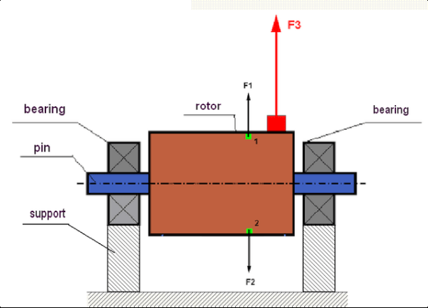
Sl.1 Rotor i centrifugalne sile.
U savršeno balansiranom rotoru, njegova masa je simetrično raspoređena u odnosu na osu rotacije. To znači da bilo koji element rotora može odgovarati drugom elementu koji se nalazi simetrično u odnosu na osu rotacije. Tokom rotacije, na svaki element rotora djeluje centrifugalna sila usmjerena u radijalnom pravcu (okomito na osu rotacije rotora). U balansiranom rotoru, centrifugalna sila koja djeluje na bilo koji element rotora uravnotežena je centrifugalnom silom koja djeluje na simetrični element. Na primjer, na elemente 1 i 2 (prikazane na sl.1 i obojene zeleno) djeluju centrifugalne sile F1 i F2: jednake po vrijednosti i apsolutno suprotne po pravcu. Ovo važi za sve simetrične elemente rotora i tako je ukupna centrifugalna sila koja djeluje na rotor jednaka 0, rotor je balansiran. Ali ako je simetrija rotora narušena (na Slici 1, asimetrični element je označen crveno), tada na rotor počinje djelovati neuravnotežena centrifugalna sila F3.
Tokom rotacije, ova sila mijenja smjer zajedno sa rotacijom rotora. Dinamičko opterećenje proizašlo iz ove sile prenosi se na ležajeve, što dovodi do njihovog ubrzanog trošenja. Pored toga, pod uticajem ove promjenjive sile, dolazi do cikličke deformacije nosača i temelja na kojem je rotor fiksiran, što proizvodi vibracije. Da bi se eliminirala neuravnoteženost rotora i pratećih vibracija, potrebno je postaviti mase za balansiranje koje će obnoviti simetriju rotora.
Balansiranje rotora je operacija eliminacije neuravnoteženosti dodavanjem masa za balansiranje.
Zadatak balansiranja je da se odredi vrijednost i mjesta (ugao) instalacije jedne ili više masa za balansiranje.
Vrste rotora i nebalansiranosti
S obzirom na čvrstoću materijala rotora i veličinu centrifugalnih sila koje na njega djeluju, rotori se mogu podijeliti u dvije vrste: krute i fleksibilne.
Kruti rotori se u radnim uvjetima pod utjecajem centrifugalne sile mogu blago deformirati, pa se utjecaj te deformacije u proračunima može zanemariti.
Deformacija fleksibilnih rotora, s druge strane, nikada ne smije biti zanemarena. Deformacija fleksibilnih rotora komplicira rješenje problema balansiranja i zahtijeva upotrebu nekih drugih matematičkih modela u poređenju sa zadatkom balansiranja krutih rotora. Važno je napomenuti da se isti rotor pri niskim brzinama rotacije može ponašati kao kruti, a pri visokim brzinama kao fleksibilni. Dalje ćemo razmatrati samo balansiranje krutih rotora.
U zavisnosti od raspodjele neubalansirane mase duž dužine rotora, mogu se razlikovati dvije vrste nebalansiranosti – statička i dinamička. Isto tako se razlikuju statičko i dinamičko balansiranje rotora.
Statička neuravnoteženost rotora javlja se bez rotacije rotora. Drugim riječima, ona je prisutna u mirovanju, kada je rotor pod utjecajem gravitacije, koja okreće „tešku tačku” prema dolje. Primjer rotora sa statičkom neuravnoteženošću prikazan je na Sl.2

Sl.2
Dinamička neuravnoteženost se javlja samo kada se rotor vrti.
Primjer rotora sa dinamičkom neuravnotežnošću prikazan je na slici 3.
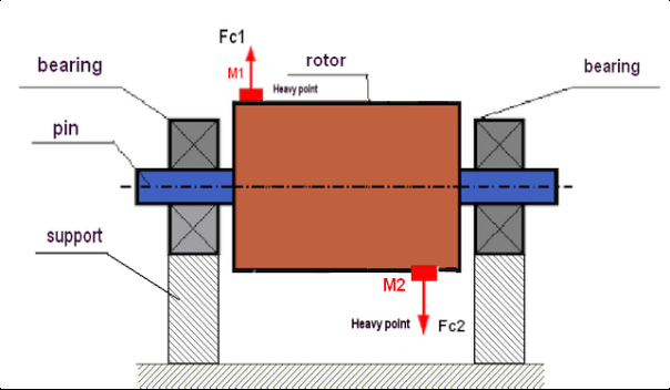
Slika 3. Dinamička neuravnoteženost rotora – spreg centrifugalnih sila
U ovom slučaju, neuravnotežene jednake mase M1 i M2 nalaze se na različitim površinama – na različitim mjestima duž dužine rotora. U statičkom položaju, tj. kada se rotor ne okreće, na rotor djeluje samo gravitacija, pa se mase međusobno uravnotežuju. U dinamici, kada se rotor okreće, na mase M1 i M2 počinju djelovati centrifugalne sile FЎ1 i FЎ2. Ove sile su jednake po vrijednosti i suprotne po smjeru. Međutim, budući da se nalaze na različitim mjestima duž dužine vratila i nisu na istoj liniji, sile se ne kompenziraju međusobno. Sile FЎ1 i FЎ2 stvaraju moment koji djeluje na rotor. Zato se ova neuravnoteženost naziva i „momentna”. Shodno tome, nekompenzirane centrifugalne sile djeluju na oslonce ležajeva, što može znatno premašiti sile na koje smo se oslanjali i također skratiti radni vijek ležajeva.
Budući da se ova vrsta neuravnoteženosti javlja samo tokom rotacije rotora, naziva se dinamičkom. Ne može se ukloniti statičkim balansiranjem (takozvano „na noževima”) niti bilo kojim sličnim načinom. Da bi se uklonila dinamička neuravnoteženost, potrebno je postaviti dva kompenzaciona tega koja će stvoriti moment jednak po vrijednosti, a suprotan po smjeru momentu koji nastaje od masa M1 i M2. Kompenzacione mase ne moraju nužno biti postavljene nasuprot masama M1 i M2 niti biti jednake njima po vrijednosti. Najvažnije je da stvaraju moment koji u potpunosti kompenzira upravo taj moment neuravnoteženosti.
Općenito, mase M1 i M2 mogu biti nejednakog opterećenja, pa će biti kombinacija statičke i dinamičke nebalansiranosti. Teorijski je dokazano da je za eliminaciju nebalansiranosti krutog rotora potrebno i dovoljno ugraditi dva težinska tereta raspoređena duž dužine rotora. Ti će tereti kompenzirati i moment koji proistječe iz dinamičke nebalansiranosti i centrifugalnu silu koja je rezultat asimetrije mase u odnosu na os rotora (statička nebalansiranost). Kao što je uobičajeno, dinamička nebalansiranost je tipična za duge rotore, kao što su vratila, a statička – za uske. Međutim, ako je uski rotor montiran pod kutom u odnosu na os, ili gore, deformiran (takozvana "oscilacija točka"), u tom slučaju će biti teško eliminirati dinamičku nebalansiranost (vidjeti Sl.4), zbog činjenice da je teško postaviti korekcijske terete koji stvaraju pravi kompenzacijski moment.
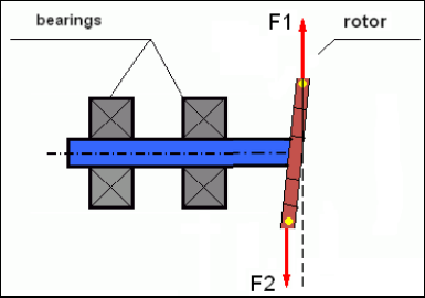
Sl.4 Dinamičko balansiranje titrajućeg kola
Budući da uski krak rotora stvara kratak moment, mogu biti potrebni korekcioni tegovi velike mase. Ali istovremeno postoji dodatna takozvana „inducirana neuravnoteženost” povezana sa deformacijom uskog rotora pod utjecajem centrifugalnih sila korekcionih masa.
Pogledajte primjer:
" Metodička uputstva o balansiranju krutih rotora" ISO 1940-1:2003 Mehaničke vibracije – Zahtjevi za kvalitetu balansiranja rotora u konstantnom (krutom) stanju – Dio 1: Specifikacija i verifikacija tolerancija balansiranja
To je vidljivo kod uskih radnih kola ventilatora, na koja, osim sile neuravnoteženosti, utiče i aerodinamička neuravnoteženost. I važno je imati na umu da je aerodinamička neuravnoteženost, zapravo aerodinamička sila, direktno proporcionalna ugaonoj brzini rotora, a za njenu kompenzaciju koristi se centrifugalna sila korekcijske mase, koja je proporcionalna kvadratu ugaone brzine. Stoga se efekat balansiranja može javiti samo na određenoj frekvenciji balansiranja. Pri drugim brzinama pojavila bi se dodatna preostala vibracija. Isto se može reći i o elektromagnetnim silama u elektromotoru, koje su također proporcionalne ugaonoj brzini. Drugim riječima, nemoguće je eliminisati sve uzroke vibracija mehanizma bilo kojim sredstvima balansiranja.
Osnove vibracija
Vibracija je reakcija dizajna mehanizma na djelovanje cikličke sile pobude. Ova sila može imati različitu prirodu.
- Centrifugalna sila koja nastaje zbog nebalansiranosti rotora je nekompenzirana sila koja utječe na "tešku točku". Posebno se ta sila i vibracije koje ona uzrokuje eliminiraju balansiranjem rotora.
- Sile interakcije, koje imaju „geometrijsku” prirodu i nastaju usljed grešaka u proizvodnji i montaži spojenih dijelova. Ove sile mogu nastati, na primjer, zbog neokruglosti rukavca vratila, grešaka u profilu zubaca zupčanika, valovitosti staza kotrljanja ležajeva, neusklađenosti spojenih vratila itd. U slučaju neokruglosti rukavaca, osa vratila će se pomjerati u zavisnosti od ugla rotacije vratila. Iako se ova vibracija ispoljava na brzini rotora, gotovo je nemoguće ukloniti je balansiranjem.
- Aerodinamičke sile nastale rotacijom radnih kola ventilatora i drugih mehanizama sa lopaticama. Hidrodinamičke sile nastale rotacijom radnih kola hidrauličnih pumpi, turbina itd.
- Elektromagnetske sile koje nastaju tijekom rada elektičnih strojeva kao rezultat, na primjer, asimetrije rotorskog namotaja, prisutnosti kratko spojenih zavoja, itd.
Veličina vibracije (na primjer, njena amplituda AB) ne zavisi samo od veličine sile pobude Fт koja djeluje na mehanizam kružnom frekvencijom ω, već i od krutosti k konstrukcije mehanizma, njegove mase m i koeficijenta prigušenja C.

Za mjerenje vibracija i balansiranje mehanizama mogu se koristiti različite vrste senzora, uključujući:
- apsolutni senzori vibracija dizajnirani za mjerenje ubrzanja vibracija (akcelerometri) i senzori brzine vibracija;
- relativni senzori vibracija vrtložne struje ili kapacitivni, namijenjeni za mjerenje vibracija.
U nekim slučajevima (kada struktura mehanizma to dozvoljava) senzori sile se mogu koristiti i za ispitivanje njegove težine vibracija.
Posebno, oni se široko koriste za mjerenje težine vibracija nosača mašina za balansiranje na krutim ležajevima.
Stoga je vibracija reakcija mehanizma na utjecaj vanjskih sila. Količina vibracije ne zavisi samo od veličine sile koja djeluje na mehanizam, već i od krutosti mehanizma. Dvije sile iste veličine mogu dovesti do različitih vibracija. U mehanizmima sa krutom strukturom nosača, čak i pri malim vibracijama, ležajne jedinice mogu biti značajno pod utjecajem dinamičkih težina. Stoga, pri balansiranju mehanizama sa krutim nogama, primjenjuju se senzori sile i vibracije (vibro akcelerometri). Senzori vibracija se koriste samo na mehanizmima sa relativno elastičnim nosačima, upravo kada djelovanje neuravnoteženih centrifugalnih sila dovodi do primjetne deformacije nosača i vibracije. Senzori sile se koriste na krutim nosačima čak i kada značajne sile nastale neuravnotežnošću ne dovode do značajnih vibracija.
Rezonancija strukture
Ranije smo pomenuli da se rotori dijele na krute i fleksibilne. Krutost ili fleksibilnost rotora ne smije se miješati sa krutošću ili pokretljivošću nosača (temelja) na kojima se rotor nalazi. Rotor se smatra krutim kada se njegova deformacija (savijanje) pod djelovanjem centrifugalnih sila može zanemariti. Deformacija fleksibilnog rotora je relativno velika: ne može se zanemariti.
U ovom članku proučavamo samo balansiranje krutih rotora. Kruti (nedeformabilni) rotor se sa svoje strane može nalaziti na krutim ili pokretljivi (fleksibilnim) osloncima. Jasno je da je ova krutost/pokretljivost oslonaca relativna i ovisi o brzini rotacije rotora i veličini rezultirajućih centrifugalnih sila. Konvencionalna granica je frekvencija slobodnih oscilacija oslonaca/temelja rotora. Za mehaničke sisteme, oblik i frekvencija slobodnih oscilacija određeni su masom i elastičnošću elemenata mehaničkog sistema. To znači da je frekvencija prirodnih oscilacija unutarnja karakteristika mehaničkog sistema i ne ovisi o vanjskim silama. Budući odmaknuta iz stanja ravnoteže, oslonci nastoje vratiti se u položaj ravnoteže zbog elastičnosti. Ali zbog inercije masivnog rotora, ovaj proces je prirode prigušenih oscilacija. Te oscilacije su vlastite oscilacije sistema rotor-oslonac. Njihova frekvencija ovisi o odnosu mase rotora i elastičnosti oslonaca.

Kada rotor počne da se rotira i kada se frekvencija njegove rotacije približi frekvenciji njegovih vlastitih oscilacija, amplituda vibracije naglo raste, što može čak dovesti do uništenja strukture.
Postoji pojava mehaničke rezonance. U rezonantnom području, promjena brzine rotacije za 100 RPM može dovesti do desetstrukog povećanja vibracije. U ovom slučaju (u rezonantnom području) faza vibracije se mijenja za 180°.
Ako je konstrukcija mehanizma loše projektirana, a radna brzina rotora je blizu prirodne frekvencije oscilacija, rad mehanizma postaje nemoguć zbog neprihvatljivo visokih vibracija. Standardne metode balansiranja su također nemoguće jer se parametri dramično mijenjaju čak i sa malenom promjenom brzine rotacije. Koriste se posebne metode u polju rezonantnog balansiranja, ali nisu dovoljno opisane u ovom članku. Frekvenciju prirodnih oscilacija mehanizma možete odrediti tijekom razgona (kada je rotor isključen) ili udaranjem s naknadnom spektralnom analizom odziva sistema na udar. "Balanset-1" pruža mogućnost određivanja prirodnih frekvencija mehaničkih struktura tim metodama.
Za mehanizme čija je radna brzina veća od rezonantne frekvencije, odnosno koji rade u rezonantnom režimu, nosači se smatraju pokretnim i koriste se senzori vibracija za mjerenje, prvenstveno akcelerometri vibracija koji mjere ubrzanje strukturnih elemenata. Za mehanizme koji rade u režimu krutih ležajeva, nosači se smatraju krutim. U ovom slučaju koriste se senzori sile.
Linearni i nelinearni modeli mehaničkog sistema
Matematički modeli (linearni) koriste se za proračune pri balansiranju krutih rotora. Linearitet modela znači da je jedna veličina direktno proporcionalno (linearno) zavisna od druge. Na primjer, ako se nekompenzirana masa na rotoru udvostruči, tada će se i vrijednost vibracije udvostručiti. Za krute rotore se može koristiti linearni model jer se takvi rotori ne deformišu. Za fleksibilne rotore više nije moguće koristiti linearni model. Kod fleksibilnog rotora, sa povećanjem mase teške tačke tokom rotacije, doći će do dodatne deformacije, a osim mase, povećat će se i poluprečnik teške tačke. Stoga će se kod fleksibilnog rotora vibracija više nego udvostručiti, a uobičajeni metodi proračuna neće raditi. Takođe, narušavanje lineariteta modela može dovesti do promjene elastičnosti nosača pri njihovim velikim deformacijama, na primjer, kada pri malim deformacijama nosača rade neki strukturni elementi, a pri velikim se u rad uključuju drugi strukturni elementi. Stoga je nemoguće balansirati mehanizme koji nisu fiksirani na temelj, a koji su, na primjer, jednostavno postavljeni na pod. Pri značajnim vibracijama, sila neuravnoteženosti može odvojiti mehanizam od poda, čime se značajno mijenjaju karakteristike krutosti sistema. Noge motora moraju biti sigurno pričvršćene, vijčani spojevi zategnuti, debljina podloški mora osigurati dovoljnu krutost itd. Kod pohabanih ležajeva moguće je značajno pomjeranje vratila i njegovi udari, što će također dovesti do narušavanja lineariteta i nemogućnosti izvođenja kvalitetnog balansiranja.
Metode i uređaji za balansiranje
Kao što je gore navedeno, balansiranje je proces poklapanja glavne centralne ose inercije sa osom rotacije rotora.
Navedeni proces može se izvesti na dva načina.
Prvi metod podrazumijeva obradu vratila rotora, koja se izvodi na takav način da osa koja prolazi kroz centre presjeka vratila poklapa sa glavnom centralnom osom inercije rotora. Ova tehnika se rijetko koristi u praksi i neće se detaljno raspravljati u ovom članku.
Drugi (najčešći) metod podrazumijeva premještanje, postavljanje ili uklanjanje korekcijskih masa na rotoru, koje su postavljene na takav način da osa inercije rotora bude što bliža osi njegove rotacije.
Premještanje, dodavanje ili uklanjanje korekcijskih masa tokom balansiranja može se izvršiti korištenjem različitih tehnoloških operacija, uključujući: bušenje, frezanje, navarivanje, zavarivanje, uvrtanje ili odvrtanje vijaka, spaljivanje laserskim ili elektronskim snopom, elektrolizu, elektromagnetno zavarivanje itd.
Proces balansiranja može se izvršiti na dva načina:
- balansirani skupovi rotora (u vlastitim ležajima);
- balansiranje rotora na balansnim mašinama.
Za balansiranje rotora u vlastitim ležajevima obično koristimo specijalizovane uređaje za balansiranje (komplete), koji nam omogućavaju da mjerimo vibracije balansiranog rotora na brzini njegove rotacije u vektorskom obliku, tj. da mjerimo i amplitudu i fazu vibracije.
Trenutno se ovi uređaji proizvode na osnovu mikroprocesorske tehnologije i (osim mjerenja i analize vibracija) omogućavaju automatizovani proračun parametara korekcijskih tegova koji moraju biti instalirani na rotoru kako bi se kompenzovala njegova neuravnoteženost.
Ovi uređaji uključuju:
- – mjerno-računska jedinica, izrađena na bazi računara ili industrijskog kontrolera;
- dva (ili više) senzora vibracija;
- senzor faznog kuta;
- oprema za montaž senzora na objektu;
- specijalizovani softver namenjen izvršavanju punog ciklusa mjerenja parametara nebalansiranosti rotora u jednoj, dvije ili više ravnina korekcije.
Za balansiranje rotora na balansirnim mašinama, pored specijalizovanog uređaja za balansiranje (mjernog sistema mašine), potreban je i pogonski mehanizam dizajniran za postavljanje rotora na oslonce i osiguravanje njegove rotacije konstantnom brzinom.
Trenutno, najčešće mašine za balansiranje postoje u dva tipa:
- nadrezonantni (sa fleksibilnim osloncima);
- krut ležaj (sa krutim osloncima).
Nadrezonantne mašine imaju relativno savitljive oslonce, izrađene, na primjer, na bazi ravnih opruga.
Vlastita frekvencija oscilacija ovih nosača je obično 2-3 puta niža od brzine balansiranih rotora, koji su na njima montirani.
Senzori vibracija (akcelerometri, senzori brzine vibracija itd.) obično se koriste za mjerenje vibracija nosača rezonantne mašine.
U mašinama za balansiranje na krutim ležajevima koriste se relativno kruti nosači, čije vlastite frekvencije oscilacija trebaju biti 2-3 puta više od brzine balansiranih rotora.
Senzori sile se obično koriste za mjerenje težine vibracija na nosačima mašine.
Prednost mašina za balansiranje na krutim ležajevima je što se mogu balansirati pri relativno niskim brzinama rotora (do 400-500 RPM), što znatno pojednostavljuje dizajn mašine i njenog temelja, kao i povećava produktivnost i sigurnost balansiranja.
Tehnika balansiranja
Balansiranje eliminira samo vibracije koje su uzrokovane asimetrijom raspodjele mase rotora u odnosu na njegovu os rotacije. Ostale vrste vibracija ne mogu se eliminirati balansiranjem!
Balansiranje se odnosi na tehnički ispravne mehanizme, čiji dizajn osigurava odsustvo rezonanci na radnom broju obrtaja, sigurno učvršćene na temelju, instalirane u ispravne ležajeve.
Neispravan mehanizam je predmet popravka, i tek zatim – balansiranja. U suprotnom, kvalitetno balansiranje je nemoguće.
Balansiranje ne može zamijeniti popravku!
Glavni zadatak balansiranja je određivanje mase i mjesta (ugla) instalacije kompenzacionih tegova, koji su uravnoteženi centrifugalnim silama.
Kao što je gore navedeno, za krute rotore generalno je potrebno i dovoljno postaviti dva kompenzaciona tega. Ovo će eliminirati i statičku i dinamičku neuravnoteženost rotora. Opšta shema mjerenja vibracija tokom balansiranja izgleda ovako:
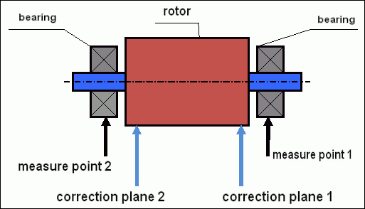
sl.5 Dinamičko balansiranje – korekcijske ravnine i mjerna mjesta
Senzori vibracija se instaliraju na nosačima ležajeva u tačkama 1 i 2. Oznaka za broj obrtaja se fiksira direktno na rotor, obično se lijepi reflektujuća traka. Oznaka za broj obrtaja se koristi od strane laserskog tahometra za određivanje broja obrtaja rotora i faze signala vibracija.
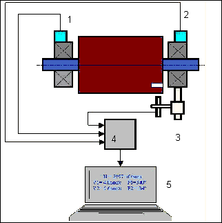
sl. 6. Instalacija senzora tijekom uravnoteživanja u dvije ravnine, korištenjem Balanset-1
1,2-senzori vibracija, 3-faza, 4- USB mjerna jedinica, 5-laptop
U većini slučajeva, dinamičko balansiranje se izvodi metodom tri pokretanja. Ova metoda se zasniva na činjenici da se probni tegovi poznate mase instaliraju na rotor u seriji u 1 i 2 ravnini; tako se mase i mjesto instalacije balansnih tegova računaju na osnovu rezultata promjene parametara vibracija.
Mjesto instalacije težine naziva se ravnina korekcije. Obično se ravnine korekcije biraju u području oslonaca ležaja na koje je rotor montiran.
Početna vibracija se mjeri pri prvom pokretanju. Zatim se na rotor, bliže jednoj od opore, instalira pokusna težina poznate mase. Tada se obavlja drugo pokretanje i mjerimo parametre vibracije koji bi trebali promijeniti zbog instalacije pokusne težine. Zatim se pokusna težina u prvoj ravnini uklanja i instalira u drugoj ravnini. Obavlja se treće pokretanje i mjere se parametri vibracije. Kada se pokusna težina uklonji, program automatski izračunava masu i mjesto (uglove) instalacije uravnoteživačkih težina.
Suština postavljanja probnih tegova je određivanje kako sistem reaguje na promjenu neuravnoteženosti. Kada znamo mase i lokaciju uzoraka tegova, program može izračunati tako zvane koeficijente uticaja, koji pokazuju kako uvođenje poznate neuravnoteženosti utiče na parametre vibracija. Koeficijenti uticaja su karakteristike samog mehaničkog sistema i zavise od krutosti nosača i mase (inercije) sistema rotor-nosač.
Za isti tip mehanizama istog dizajna, koeficijenti uticaja će biti slični. Možete ih sačuvati u memoriji računara i koristiti ih kasnije za balansiranje istog tipa mehanizama bez izvođenja probnih pokretanja, što značajno poboljšava efikasnost balansiranja. Također treba napomenuti da se masa probnih tegova treba birati tako da se parametri vibracija značajno mijenjaju pri instalaciji probnih tegova. U suprotnom, greška u računanju koeficijenata uticaja raste i kvalitet balansiranja se pogoršava.
Priručnik za uređaj Balanset-1 pruža formulu pomoću koje možete približno odrediti masu pokusne težine, ovisno o masi i brzini rotacije uravnoteženog rotora. Kao što možete razumjeti sa sl. 1 centrifugalna sila djeluje u radijalnom smjeru, odnosno okomito na os rotora. Stoga bi senzori vibracije trebali biti instalirani tako da je njihova os osjetljivosti također usmjerena u radijalnom smjeru. Obično je krutost temelja u horizontalnom smjeru manja, tako da je vibracija u horizontalnom smjeru veća. Stoga, da bi se povećala osjetljivost, senzori bi trebali biti instalirani tako da je njihova os osjetljivosti također usmjerena horizontalno. Iako nema temeljne razlike. Osim vibracije u radijalnom smjeru, potrebno je kontrolirati vibraciju u aksijalnom smjeru, duž osi rotacije rotora. Ova vibracija obično nije uzrokovana neravnotežom, već drugim razlozima, uglavnom zbog neusklađenosti i neusklađenosti vratila povezanih kroz spojku. Ova vibracija se ne uklanja uravnoteživanjem, u tom slučaju potrebno je usklađivanje. U praksi, obično u takvim mehanizmima postoji neravnoteža rotora i neusklađenost vratila, što uvelike otežava zadatak uklanjanja vibracije. U takvim slučajevima, prvo morate uskladiti, a zatim uravnotežiti mehanizam. (Iako sa jakim zakretanjem neravnoteže, vibracija se javlja i u aksijalnom smjeru zbog "uvijanja" strukture temelja).
Točnost mjerenja i analiza greške
Razumijevanje točnosti mjerenja kritično je za profesionalne operacije uravnoteživanja. Balanset-1A pruža sljedeću preciznost mjerenja:
| Parametar | Formula točnosti | Primjer (za tipične vrijednosti) |
|---|---|---|
| RMS brzina vibracije | ±(0.1 + 0.1×Vizmjereno) mm/s | Za 5 mm/s: ±0,6 mm/s Za 10 mm/s: ±1,1 mm/s |
| Frekvencija rotacije | ±(1 + 0.005×Nizmjereno) o/min | Za 1000 rpm: ±6 rpm Za 3000 rpm: ±16 rpm |
| Mjerenje Faze | ±1° | Stalna točnost na svim brzinama |
⚠️ Kritično za točno uravnoteživanje
- !Pokusna težina mora uzrokovati >20-30% promjenu amplitude i/ili >20-30° promjenu faze
- !Ako su promjene manje, greške mjerenja znatno se povećavaju
- !Amplituda vibracije i stabilnost faze ne bi trebale varirati više od 10-15% između mjerenja
- !Ako varijacija prekoračuje 15%, provjerite rezonantne uslove ili mehaničke defekte
Kriteriji za procenu kvalitete mehanizama balansiranja
Kvalitet balansiranja rotora (mehanizama) može se procijeniti na dva načina. Prva metoda podrazumijeva upoređivanje vrijednosti preostale neuravnoteženosti određene tokom balansiranja sa tolerancijom za preostalu neuravnoteženost. Navedene tolerancije za različite klase rotora instalirane u standardu ISO 21940-11 «Mehaničke vibracije – Balansiranje rotora – Dio 11: Postupci i tolerancije za rotore s krutim ponašanjem» (ranije ISO 1940-1).
Međutim, primjena ovih tolerancija ne može u potpunosti garantirati operativnu pouzdanost mehanizma povezanu sa postizanjem minimalnog nivoa vibracija. To je zbog činjenice da se vibracije mehanizma ne određuju samo količinom sile povezane sa rezidualnom neuravnoteženosti njegovog rotora, već zavise i od niza ostalih parametara, uključujući: krutost K strukturnih elemenata mehanizma, njegovu masu M, koeficijent prigušenja i brzinu. Stoga se, da bi se procijenile dinamičke karakteristike mehanizma (uključujući kvalitetu njegovog balansiranja), u nekim slučajevima preporučuje procena nivoa rezidualnih vibracija mehanizma, što je regulirano nizom standarda.
Najčešći standard koji reguliše dozvoljene nivoe vibracija mehanizama je ISO 10816-3:2009 Preview Mehaničke vibracije — Ocjena vibracija mašina mjerenjima na nerotirajućim dijelovima — Dio 3: Industrijske mašine s nominalnom snagom iznad 15 kW i nominalnim brzinama između 120 o/min i 15 000 o/min, mjereno in situ.»
Njegovom pomoću možete postaviti toleranciju na sve tipove mašina, uzimajući u obzir snagu njihovog električnog pogona.
Pored ovog univerzalnog standarda, postoji niz specijalizovanih standarda razvijenih za specifične tipove mehanizama. Na primjer,
- ISO 14694:2003 "Industrijski ventilatori – Specifikacije za kvalitetu balansiranja i nivoe vibracija"
- ISO 7919-1-2002 “Vibracije mašina bez povratno-translatornog kretanja. Mjerenja na rotirajućim vratilima i kriteriji ocjenjivanja. Opšte smjernice.»
🛡️ Važna Sigurnosna Razmatranja za EU Usklađenost
- !Procena Rizika je Obavezna: Izvedite EN ISO 12100 procenu rizika prije operacija balansiranja
- !Kvalificirano osoblje: Samo obučeni i sertificirani kadovi trebali bi izvoditi operacije balansiranja
- !Lična zaštitna oprema: Uvijek koristite odgovarajuću zaštitnu opremu prema EN 166 (zaštita očiju) i EN 352 (zaštita sluha)
- !Nužne mjere: Uspostavite jasne procedure hitnog gašenja i osigurajte da su svi operateri upoznati s njima
- !Dokumentacija: Održavajte detaljne zapise svih operacija balansiranja radi pracenja i usklađenosti
EU usklađenost i sigurnosne informacije
Izjava o usklađenosti
Prenosivi balancer Balanset-1A usklađen je sa sljedećim direktivama i standardima Evropske unije:
| EU Direktiva/Standard | Detalji Usklađenosti | Sigurnosni Zahtjevi |
|---|---|---|
| Direktiva o Mašinama 2006/42/EC | Sigurnosni zahtjevi za mašine i sigurnosne komponente | Procena rizika, sigurnosne upute, CE oznaka |
| EMC Direktiva 2014/30/EU | Zahtjevi elektromagnetske kompatibilnosti | Otpornost na elektromagnetne smetnje |
| RoHS Direktiva 2011/65/EU | Ograničenje štetnih supstanci | Komponente bez olova, žive i kadmija |
| WEEE Direktiva 2012/19/EU | Električna i elektronska oprema kao otpad | Pravilna procedura za odlaganje i reciklažu |
| EN ISO 12100:2010 | Sigurnost mašina - Opće principe za dizajn | Procjena rizika i smanjenje rizika |
| EN 60825-1:2014 | Sigurnost laserskih proizvoda - Dio 1 | Zahtjevi za sigurnost laserskog sistema klase 2 |
| EN ISO 14120:2015 | Zaštitne ograde - Opći zahtjevi | Zaštita od opasnosti rotacijskih mašina |
Standardi električne sigurnosti
- ✓EN 61010-1: Zahtjevi sigurnosti za električne uređaje za mjerenje, kontrolu i laboratorijsku upotrebu
- ✓EN 60950-1: Sigurnost opreme informacijske tehnologije (uređaj napajan USB-om)
- ✓IEC 61000 serija: Standardi elektromagnetne kompatibilnosti
- ✓Radni napon: 5V DC preko USB-a (ekstra nizak napon)
- ✓Potrošnja energije: < 2.5W
- ✓Klasa zaštite: IP54 (zaštićeno od prašine; otporno na prskanje vode)
Sigurnost rotirajuće opreme
⚠️ Obavezni sigurnosni postupci (EN ISO 12100)
UPOZORENJE: Pri radu s rotirajućom mašinerijom, poštujte sljedeće sigurnosne zahtjeve:
- !EN ISO 14118: Sprječavanje neželjenog pokretanja - Koristite LOTO postupke prije instalacije senzora
- !EN ISO 14120: Osigurajte da je sva rotirajuća oprema pravilno zaštićena
- !EN ISO 13857: Održavajte minimalnu sigurnu distancu od rotirajućih dijelova (500mm za tijelo, 120mm za prste)
- !Lična zaštitna oprema: Nosite sigurnosne naočale prema EN 166, zaštitu sluha prema EN 352 i izbjegavajte labavu odjeću
- !Nikada ne instaliraju senzore ili ispitne težine na rotirajuće strojeve koji su u pogonu
- !Osigurajte da je stroj potpuno zaustavljen i osiguran prije instalacije senzora
- !Hitno zaustavljanje: Mora biti dostupno na udaljenosti od 3 metra od položaja operatora
- !Samo kvalificirani i certificirani kadrovi trebaju izvršavati operacije balansiranja
Klasifikacija laserske sigurnosti
🔴 Laserski uređaj klase 2 (EN 60825-1:2014)
- Talasna dužina: 650 nm (crvena vidljiva svjetlost)
- Maksimalna izlazna snaga: < 1 mW
- Promjer snopa: 3-5 mm na 100mm udaljenosti
- Divergencija: < 1,5 mrad
- Klasifikacija sigurnosti: Sigurno za oko pri kratkotrajnoj izloženosti (< 0,25 sek)
- Obavezno označavanje: "LASERSKO ZRAČENJE - NE GLEDAM U SNOP - LASERSKI PROIZVOD KLASE 2"
- Klasa pristupa: Neograničeno (pristup dozvoljen opšte javnosti)
Procedure laserske sigurnosti:
- Nikada namjerno ne gledajte u laserski snop
- Ne usmjeravajte laser na osobe, vozila ili zrakoplove
- Izbjegavajte gledanje u laserski snop sa optičkim instrumentima (teleskopi, dalekozori)
- Budite svjesni spekularne refleksije sa sjajnih površina
- Isključite laser kada nije u upotrebi
- Odmah prijavite bilo koju izloženost lasera očima
- Koristite zaštitne naočale za laser (OD 2+ na 650nm) za duži boravak
Tačnost mjerenja i kalibracija
| Parametar | Tačnost | Frekvencija kalibracije |
|---|---|---|
| Amplituda vibracija | ±5% od očitanja | Godišnje ili nakon 1000 sati |
| Mjerenje faze | ±1° | Godišnje |
| Brzina rotacije | ±0,1% od očitavanja | Godišnje |
| Osjetljivost senzora | 13 mV/(mm/s) ±10% | Pri zamjeni senzora |
Usklađenost sa zahtjevima okoline
- ✓Okruženje za rad: 5°C do 50°C, < 85% RH bez kondenzacije
- ✓Okruženje za skladištenje: -20°C do 70°C, < 95% RH bez kondenzacije
- ✓Nadmorska visina: Do 2000m iznad razine mora
- ✓Otpornost na vibracije: IEC 60068-2-6 (10-500 Hz, 2g ubrzanja)
- ✓Otpornost na udare: IEC 60068-2-27 (15g, trajanje 11ms)
- ✓IP klasa zaštite: IP54 (zaštićeno od prašine; otporno na prskanje vode)
Zahtjevi za rad
- ✓Operatori moraju biti obučeni u sigurnosti makinskog rada prema EU standardima
- ✓Procjena rizika obavezna prema EN ISO 12100 prije korištenja
- ✓Održavajte opremu prema specifikacijama proizvođača
- ✓Odmah prijavite sve sigurnosne incidente ili kvarove opreme
- ✓Vodite detaljne zapise svih operacija uravnotežavanja radi praćenja
Zahtjevi za dokumentaciju
Za usklađenost sa EU, čuvajte sljedeću dokumentaciju:
- ✓Dokumentacija procjene rizika prema EN ISO 12100
- ✓Zapisi obuke operatera i sertifikati
- ✓Logovi kalibracije i održavanja opreme
- ✓Zapisi balansiranja sa datumima, operaterima i rezultatima
- ✓Izvještaji o sigurnosnim incidentima i korektivne mjere
- ✓Dokumentacija izmjena ili popravke opreme
Tehnička podrška i servis
Za tehničku podršku, usluge kalibracije i rezervne dijelove:
- ✓Proizvođač: Vibromera
- ✓Lokacija: Narva, Estonija (EU)
- ✓Web stranica: https://vibromera.eu
- ✓Jezici podrške: Svi glavni jezici. Dostupna tekstualna komunikacija.
- ✓Pokrivanje servisom: Dostupna dostava širom svijeta
- ✓Garancija: 12 mjeseci od datuma kupnje
- ✓Usluga kalibracije: Dostupno kroz ovlaštene centre servisa

