איזון גל הינע: מדריך מקיף
מכשירים לאיזון דינמי של גלי הינע ומערכת מדידה למכונות איזון Balanset-4 – 6,803 אירו
דמיינו שאתם נוהגים במשאית ולפתע מרגישים רטט חזק או שומעים נקישה חזקה בעת האצה או החלפת הילוכים. זה יותר מסתם מטרד - זה יכול להיות סימן לגל הינע לא מאוזן. עבור מהנדסים וטכנאים, רעידות ורעשים כאלה מצביעים על אובדן יעילות, בלאי מואץ של רכיבים וזמן השבתה שעלול להיות יקר אם לא מטפלים.
במדריך מקיף זה, אנו מספקים פתרונות מעשיים לבעיות איזון גל הינע. תלמדו מהו גל הינע ומדוע הוא זקוק לאיזון, תזהו את התקלות הנפוצות הגורמות לרעידות או רעש, ותעקבו אחר תהליך ברור שלב אחר שלב לאיזון דינמי של גל הינע. על ידי יישום שיטות עבודה מומלצות אלו, תוכלו לחסוך כסף על תיקונים, להפחית את זמן פתרון הבעיות ולהבטיח שהמכונה או הרכב שלכם יפעלו בצורה אמינה עם רעידות מינימליות.
תוכן העניינים
- 1. Types of Driveshafts
- 2. Universal Joint Drive Malfunctions
- 3. Driveshaft Balancing
- 4. Modern Balancing Machines for Driveshafts
- 5. Preparation for Driveshaft Balancing
- 6. Driveshaft Balancing Procedure
- 7. Recommended Balancing Accuracy Classes for Rigid Rotors


1. Types of Driveshafts
A universal joint drive (driveshaft) is a mechanism that transmits torque between shafts that intersect at the center of the universal joint and can move relative to each other at an angle. In a vehicle, the driveshaft transmits torque from the gearbox (or transfer case) to the driven axles in the case of a classical or all-wheel-drive configuration. For all-wheel-drive vehicles, the universal joint usually connects the driven shaft of the gearbox to the drive shaft of the transfer case, and the driven shafts of the transfer case to the drive shafts of the main drives of the driven axles.
יחידות המותקנות על השלדה (כגון תיבת ההילוכים ותיבת ההעברה) יכולות לנוע זו ביחס לזו עקב עיוות התומכים שלהן והשלדה עצמה. בינתיים, סרני ההינע מחוברים לשלדה דרך המתלה ויכולים לנוע יחסית לשלדה וליחידות המותקנות עליה עקב עיוות האלמנטים האלסטיים של המתלה. תנועה זו יכולה לשנות לא רק את זוויות גלי ההינע המחברים את היחידות, אלא גם את המרחק בין היחידות.
The universal joint drive has a significant disadvantage: the non-uniform rotation of the shafts. If one shaft rotates uniformly, the other does not, and this non-uniformity increases with the angle between the shafts. This limitation prevents the use of a universal joint drive in many applications, such as in the transmission of front-wheel-drive vehicles, where the main issue is transmitting torque to the turning wheels. This disadvantage can be partially compensated by using double universal joints on one shaft, which are turned a quarter of a turn relative to each other. However, in applications requiring uniform rotation, constant velocity joints (CV joints) are typically used instead. CV joints are a more advanced but also more complex design serving the same purpose.
Universal joint drives can consist of one or more universal joints connected by driveshafts and intermediate supports.
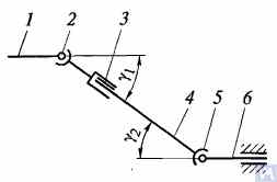
Figure 1. Diagram of a universal joint drive: 1, 4, 6 — driveshafts; 2, 5 — universal joints; 3 — compensating connection; u1, u2 — angles between shafts
באופן כללי, הנעה של מפרק אוניברסלי מורכבת ממפרקים אוניברסליים 2 ו-5, צירי הנעה 1, 4 ו-6, וחיבור מפצה 3. לעיתים גל ההינע מותקן על תומך ביניים המחובר למשקוף שלדת הרכב. מפרקים אוניברסליים מבטיחים את העברת המומנט בין צירים שציריהם מצטלבים בזווית. מפרקים אוניברסליים מחולקים לסוגים לא אחידים ומהירות קבועה. מפרקים לא אחידים מסווגים עוד לסוגים אלסטיים ונוקשים. מפרקים במהירות קבועה יכולים להיות מסוג כדורי עם חריצים מפרידים, מסוג כדורי עם ידית מפרידת, וסוג זיזים. הם מותקנים בדרך כלל בהנעה של הגלגלים הנשלטים המובילים, כאשר הזווית בין הצירים יכולה להגיע ל-45°, ומרכז המפרק האוניברסלי חייב לחפוף לנקודת החיתוך של צירי הסיבוב של הגלגל וציר הסיבוב שלו.
מפרקים אוניברסליים אלסטיים מעבירים מומנט בין צירים עם צירים מצטלבים בזווית של 2...3° עקב עיוות אלסטי של רכיבי החיבור. מפרק מהירות קשיח לא אחיד מעביר מומנט מציר אחד למשנהו באמצעות חיבור נייד של חלקים קשיחים. הוא מורכב משני עולים - 3 ו-5, שבתוך החורים הגליליים שלהם מותקנים הקצוות A, B, V ו-G של רכיב החיבור - הצלב 4, על מיסבים. העולים מחוברים באופן קשיח לצירים 1 ו-2. עול 5 יכול להסתובב סביב ציר BG של הצלב ובו זמנית, יחד עם הצלב, להסתובב סביב ציר AV, ובכך לאפשר העברת סיבוב מציר אחד למשנהו עם זווית משתנה ביניהם.
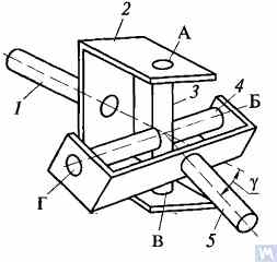
Figure 2. Diagram of a rigid non-uniform velocity universal joint
If shaft 7 rotates around its axis by an angle α, then shaft 2 will rotate by an angle β over the same period. The relationship between the rotation angles of shafts 7 and 2 is determined by the expression tanα = tanβ * cosγ, כאשר γ הוא הזווית שבה ממוקמים צירי הצירים. ביטוי זה מציין כי הזווית β לעיתים קטנה מזווית α, שווה לה או גדולה מזווית α. שוויון זוויות אלו מתרחש בכל 90° של סיבוב של ציר 7. לכן, עם סיבוב אחיד של ציר 1, המהירות הזוויתית של ציר 2 אינה אחידה ומשתנה בהתאם לחוק סינוסואידלי. חוסר האחידות של סיבוב ציר 2 הופך משמעותי יותר ככל שזווית γ בין צירי הציר עולה.
If the non-uniform rotation of shaft 2 is transmitted to the shafts of the units, additional pulsating loads will occur in the transmission, increasing with the angle γ. To prevent the non-uniform rotation of shaft 2 from being transmitted to the unit shafts, two universal joints are used in the universal joint drive. They are installed so that the angles γ1 and γ2 are equal; the forks of the universal joints, fixed on the non-uniformly rotating shaft 4, should be positioned in the same plane.
תכנון החלקים העיקריים של מפרק אוניברסלי מוצג באיור 3. מפרק אוניברסלי בעל מהירות לא אחידה מורכב משני עולים (1) המחוברים באמצעות צלב (3). לאחד העולים יש לפעמים אוגן, בעוד שהשני מרותך לצינור גל ההינע או בעל קצה חריץ (6) (או שרוול) לחיבור לגל ההינע. גלגלי הצלב מותקנים בעיניים של שני העולים על גבי מיסבי מחט (7). כל מיסב נמצא בתוך מארז (2) ומוחזק בעיני העול בעזרת מכסה, המחובר לעול בעזרת שני ברגים הנעולים על ידי לשוניות על דיסקית. במקרים מסוימים, המסבים מאובטחים בעולים בעזרת טבעות הצמדה. כדי לשמור על חומר הסיכה במיסב ולהגן עליו מפני מים ולכלוך, יש אטם גומי הידוק עצמי. החלל הפנימי של הצלב ממולא בגריז דרך צינור גריז, המגיע למסבים. לצלב יש בדרך כלל שסתום בטיחות כדי להגן על האטם מפני נזק עקב לחץ הגריז הנשאב לתוך הצלב. החיבור החריץ (6) משומן באמצעות צינור הגריז (5).
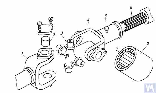
Figure 3. Details of a rigid non-uniform velocity universal joint
הזווית המקסימלית בין צירי הצירים המחוברים באמצעות מפרקים אוניברסליים קשיחים בעלי מהירות לא אחידה בדרך כלל אינה עולה על 20°, מכיוון שהיעילות פוחתת משמעותית בזוויות גדולות יותר. אם הזווית בין צירי הציר משתנה בטווח של 0...2%, גלגלי הצלב מעוותים על ידי מיסבי המחט, מה שגורם לכשל מהיר של המפרק האוניברסלי.
בתיבות הילוכים של כלי רכב זחלי במהירות גבוהה, משתמשים לעתים קרובות במפרקים אוניברסליים עם צימוד הילוכים, המאפשרים העברת מומנט בין צירים עם צירים המצטלבים בזוויות של עד 1.5...2°.
Driveshafts are typically made tubular, using special steel seamless or welded tubes. The yokes of the universal joints, splined sleeves, or tips are welded to the tubes. To reduce the transverse loads acting on the driveshaft, dynamic balancing is performed with the universal joints assembled. Imbalance is corrected by welding balancing plates to the driveshaft or sometimes by installing balancing plates under the bearing caps of the universal joints. The relative position of the splined connection parts after assembly and balancing of the universal joint drive at the factory is usually marked with special labels.
The compensating connection of the universal joint drive is usually made in the form of a splined connection, allowing axial movement of the universal joint drive parts. It consists of a splined tip that fits into the splined sleeve of the universal joint drive. Lubrication is introduced into the splined connection through a grease fitting or applied during assembly and replaced after prolonged use of the vehicle. A seal and a cover are typically installed to prevent grease leakage and contamination.
For long driveshafts, intermediate supports are usually used in universal joint drives. An intermediate support typically consists of a bracket bolted to the vehicle frame cross member, in which a ball bearing is mounted in a rubber elastic ring. The bearing is sealed on both sides with caps and has a lubrication device. The elastic rubber ring helps to compensate for assembly inaccuracies and bearing misalignment that may occur due to frame deformations.
A universal joint with needle bearings (Figure 4a) consists of yokes, a cross, needle bearings, and seals. The cups with needle bearings are fitted onto the trunnions of the cross and sealed with seals. The cups are secured in the yokes with snap rings or caps fastened with screws. Universal joints are lubricated through a grease fitting via internal drillings in the cross. A safety valve is used to eliminate excess oil pressure in the joint. During uniform rotation of the driving yoke, the driven yoke rotates non-uniformly: it advances and lags behind the driving yoke twice per revolution. To eliminate non-uniform rotation and reduce inertial loads, two universal joints are used.
In the drive to the front driving wheels, constant velocity universal joints are installed. The constant velocity joint drive of GAZ-66 and ZIL-131 vehicles consists of yokes 2, 5 (Figure 4b), four balls 7, and a central ball 8. The driving yoke 2 is integral with the inner axle shaft, while the driven yoke is forged together with the outer axle shaft, at the end of which the wheel hub is fixed. The driving moment from yoke 2 to yoke 5 is transmitted through balls 7, which move along circular grooves in the yokes. The central ball 8 serves to center the yokes and is held in place by studs 3, 4. The rotation frequency of yokes 2, 5 is the same due to the symmetry of the mechanism relative to the yokes. The change in shaft length is ensured by the free splined connections of the yokes with the shaft.
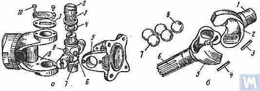
Figure 4. Universal Joints: a — universal joint: 1 — cap; 2 — cup; 3 — needle bearing; 4 — seal; 5, 9 — yokes; 6 — safety valve; 7 — cross; 8 — grease fitting; 10 — screw; b — constant velocity universal joint: 1 — inner axle shaft; 2 — driving yoke; 3, 4 — studs; 5 — driven yoke; 6 — outer axle shaft; 7 — balls; 8 — central ball
2. Universal Joint Drive Malfunctions
Universal joint drive malfunctions typically manifest as sharp knocks in the universal joints that occur when the vehicle is moving, especially during shifts between gears and sudden increases in the engine crankshaft speed (for example, when transitioning from engine braking to acceleration). A sign of universal joint malfunction can be its heating to a high temperature (over 100°C). This happens due to significant wear of the bushings and trunnions of the universal joint, needle bearings, crosses, and splined connections, resulting in misalignment of the universal joint and significant impact axial loads on the needle bearings. Damage to the cork seals of the universal joint cross leads to rapid wear of the trunnion and its bearing.
During maintenance, the universal joint drive is checked by sharply rotating the driveshaft by hand in both directions. The degree of free rotation of the shaft determines the wear of the universal joints and splined connections. Every 8-10 thousand kilometers, the condition of the bolted connections of the driven shaft flanges of the gearbox and the drive shaft of the main transmission gear with the flanges of the end universal joints and the fastening of the intermediate support of the driveshaft are checked. The condition of the rubber boots on the splined connections and the cork seals of the universal joint cross is also checked. All fastening bolts must be tightened fully (tightening torque 8-10 kgf·m).
Needle bearings of the universal joints are lubricated with liquid oil used for transmission units; splined connections in most vehicles are lubricated with greases (US-1, US-2, 1-13, etc.); the use of grease for lubricating needle bearings is strictly prohibited. In some vehicles, splined connections are lubricated with transmission oil. The intermediate support bearing, mounted in a rubber sleeve, practically does not require lubrication, as it is lubricated during assembly at the factory. The support bearing of the ZIL-130 vehicle is lubricated with grease through a pressure fitting during regular maintenance (every 1100-1700 km).
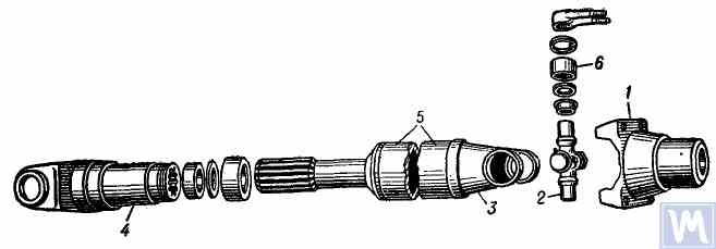
Figure 5. Universal joint drive: 1 — flange for securing the driveshaft; 2 — universal joint cross; 3 — universal joint yoke; 4 — sliding yoke; 5 — driveshaft tube; 6 — needle roller bearing with closed end
The universal joint drive consists of two universal joints with needle bearings, connected by a hollow shaft, and a sliding yoke with involute splines. To ensure reliable protection from dirt and provide good lubrication of the splined connection, the sliding yoke (6), connected to the secondary shaft (2) of the gearbox, is placed in an extension (1) attached to the gearbox housing. Additionally, this location of the splined connection (outside the zone between the joints) significantly increases the stiffness of the universal joint drive and reduces the likelihood of shaft vibrations when the sliding splined connection wears out.
גל ההינע עשוי מצינור בעל דופן דקה המופעלת באמצעות ריתוך חשמלי (8), שאליו שני עולים זהים (9) מחוברים בלחץ בכל קצה ולאחר מכן מרותכים בריתוך קשת. בתי מיסב המחטים (18) של הצלב (25) מחוברים בלחץ לתוך עיניות העולים (9) ומאובטחים באמצעות טבעות קפיציות (20). כל מיסב מפרק אוניברסלי מכיל 22 מחטים (21). מכסים חתומים (24) מחוברים בלחץ על גלגלי החיבור הבולטים של הצלבים, שאליהם מותקנות טבעות שעם (23). המסבים משומנים באמצעות מחבר גריז זוויתי (17) המוברג לחור הברגה במרכז הצלב, המחובר דרך תעלות בגלגלי החיבור של הצלב. בצד הנגדי של צלב המפרק האוניברסלי, ממוקם שסתום בטיחות (16) במרכזו, שנועד לשחרר עודפי גריז בעת מילוי הצלב והמיסבים, ולמנוע הצטברות לחץ בתוך הצלב במהלך הפעולה (השסתום מופעל בלחץ של כ-3.5 ק"ג/ס"מ²). הצורך לכלול שסתום בטיחות נובע מהעובדה שעלייה מוגזמת בלחץ בתוך הצלב עלולה לגרום נזק (בליטה) של אטמי השעם.
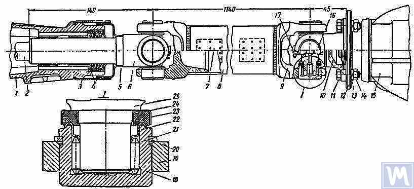
Figure 6. Driveshaft Assembly: 1 — gearbox extension; 2 — secondary shaft of the gearbox; 3 and 5 — dirt deflectors; 4 — rubber seals; 6 — sliding yoke; 7 — balancing plate; 8 — driveshaft tube; 9 — yoke; 10 — flange yoke; 11 — bolt; 12 — flange of the rear axle drive gear; 13 — spring washer; 14 — nut; 15 — rear axle; 16 — safety valve; 17 — angular grease fitting; 18 — needle bearing; 19 — yoke eye; 20 — spring retaining ring; 21 — needle; 22 — washer with toroidal end; 23 — cork ring; 24 — stamped cap; 25 — cross
גל ההינע, המורכב עם שני המפרקים האוניברסליים, מאוזן בקפידה באופן דינמי בשני קצותיו על ידי ריתוך לוחות איזון (7) לצינור. לכן, בעת פירוק הגל, יש לסמן בקפידה את כל חלקיו כדי שניתן יהיה להרכיבם מחדש במיקומיהם המקוריים. אי הקפדה על הוראות אלה משבשת את איזון הגל, וגורמת לרעידות שעלולות לפגוע בתיבת ההילוכים ובגוף הרכב. אם חלקים בודדים נשחקים, במיוחד אם הצינור מתכופף עקב פגיעה ואי אפשר לאזן את הגל באופן דינמי לאחר ההרכבה, יש להחליף את הגל כולו.
Possible Driveshaft Malfunctions, Their Causes, and Solutions
| Cause of Malfunction | Solution |
|---|---|
| Driveshaft Vibration | |
| 1. Shaft bending due to an obstacle | 1. Straighten and dynamically balance the assembled shaft or replace the assembled shaft |
| 2. Bearing and cross wear | 2. Replace bearings and crosses and dynamically balance the assembled shaft |
| 3. Wear of extension bushings and sliding yoke | 3. Replace the extension and sliding yoke and dynamically balance the assembled shaft |
| Knocks When Starting and Coasting | |
| 1. Wear of sliding yoke splines or secondary gearbox shaft | 1. Replace worn parts. When replacing the sliding yoke, dynamically balance the assembled shaft |
| 2. Loose bolts securing the flange yoke to the rear axle drive gear flange | 2. Tighten bolts |
| Oil Throwing from Universal Joint Seals | |
| Wear of cork rings in universal joint seals | Replace cork rings, maintaining the relative position of all driveshaft parts during reassembly. If there is wear on crosses and bearings, replace the bearings and crosses and dynamically balance the assembled shaft |
3. Driveshaft Balancing
After repairing and assembling the driveshaft, it is dynamically balanced on a machine. One design of a balancing machine is shown in Figure 7. The machine consists of a plate (18), a pendulum frame (8) mounted on four vertical elastic rods (3), ensuring its oscillation in the horizontal plane. A bracket and front headstock (9), secured on a bracket (4), are mounted on the longitudinal tubes of the pendulum frame (8). The rear headstock (6) is on a movable traverse (5), allowing dynamic balancing of driveshafts of different lengths. The headstock spindles are mounted on precision ball bearings. The spindle of the front headstock (9) is driven by an electric motor installed in the machine base, through a V-belt drive and an intermediate shaft, on which a limb (10) (graduated disk) is mounted. Additionally, two stands (15) with retractable locking pins (17) are installed on the machine plate (18), ensuring the fixation of the front and rear ends of the pendulum frame depending on the balancing of the front or rear end of the driveshaft.
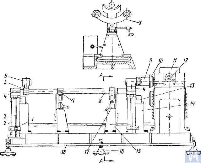
Figure 7. Dynamic Balancing Machine for Driveshafts
1—clamp; 2—dampers; 3—elastic rod; 4—bracket; 5—movable traverse; 6—rear headstock; 7—crossbar; 8—pendulum frame; 9—front driving headstock; 10—limb-disk; 11—millivoltmeter; 12—limb of the commutator-rectifier shaft; 13—magnetoelectric sensor; 14—fixed stand; 15—fixator stand; 16—support; 17—fixator; 18—support plate
The fixed stands (14) are mounted at the rear of the machine plate, and magnetoelectric sensors (13) are installed on them, with rods connected to the ends of the pendulum frame. To prevent resonance vibrations of the frame, dampers (2) filled with oil are installed under the brackets (4).
במהלך איזון דינמי, מכלול גל ההינע עם עול ההזזה מותקן ומאובטח על המכונה. קצה אחד של גל ההינע מחובר באמצעות עול אוגן לאוגן של ראש ההנעה הקדמי, והקצה השני באמצעות צוואר התמיכה של עול ההזזה לשרוול המסונן של ראש ההנעה האחורי. לאחר מכן נבדקת קלות הסיבוב של גל ההינע, וקצה אחד של מסגרת המטוטלת של המכונה מקובע באמצעות הקיבוע. לאחר הפעלת המכונה, איבר המיישר מסובב נגד כיוון השעון, מה שמביא את מחט המילי-וולטמטר לקריאה המקסימלית שלה. קריאת המילי-וולטמטר תואמת את גודל חוסר האיזון. סקלת המילי-וולטמטר מדורגת בגרם-סנטימטרים או גרמים של משקל נגד. המשך סיבוב איבר המיישר נגד כיוון השעון, קריאת המילי-וולטמטר מאפסת, והמכונה נעצרת. בהתבסס על קריאת איבר המיישר, נקבעת התזוזה הזוויתית (זווית תזוזה של חוסר איזון), ועל ידי סיבוב ידני של גל ההינע, ערך זה נקבע על איבר הציר הביניים. מקום הריתוך של לוחית האיזון יהיה בחלק העליון של גל ההינע, והחלק המשוקלל יהיה בתחתית במישור התיקון. לאחר מכן, לוחית האיזון מחוברת ונקשרת בחוט דק במרחק של 10 מ"מ מהריתוך, המכונה מופעלת, ונבדקת איזון קצה גל ההינע עם הלוח. חוסר האיזון צריך להיות לא יותר מ-70 גרם לסמ"ר. לאחר מכן, לאחר שחרור קצה אחד ואבטחת הקצה השני של מסגרת המטוטלת עם מעמד הקיבוע, מתבצע איזון דינמי של הקצה השני של גל ההינע בהתאם לרצף הטכנולוגי שתואר לעיל.
Driveshafts have some balancing features. For most parts, the base for dynamic balancing is the support necks (e.g., rotors of electric motors, turbines, spindles, crankshafts, etc.), but for driveshafts, it is the flanges. During assembly, there are unavoidable gaps in different connections leading to imbalance. If the minimum imbalance cannot be achieved during balancing, the shaft is rejected. The accuracy of balancing is influenced by the following factors:
- Gap in the connection between the landing belt of the driveshaft flange and the inner hole of the clamping flange of the left and right support headstocks;
- Radial and end runout of the base surfaces of the flange;
- פערים בחיבורי הציר והמחברים. נוכחות של גריז בחלל החיבור המחובר יכולה להוביל לחוסר איזון "צף". אם זה מונע השגת דיוק האיזון הנדרש, גל ההינע מאוזן ללא גריז.
Some imbalances may be completely uncorrectable. If increased friction is observed in the universal joints of the driveshaft, the mutual influence of the correction planes increases. This leads to a decrease in the performance and accuracy of balancing.
בהתאם ל-OST 37.001.053-74, נקבעו תקני חוסר האיזון הבאים: גלי הינע עם שני מפרקים (דו-תמיכה) מאוזנים באופן דינמי, ועם שלושה (שלוש-תמיכה) - מורכבים עם תמיכת ביניים; האוגנים (יוקים) של גלי הינע ומצמדים במשקל של יותר מ-5 ק"ג מאוזנים באופן סטטי לפני הרכבת הציר או המצמד; תקני חוסר האיזון השיורי עבור גלי הינע בכל קצה או בתמיכת הביניים של גלי הינע בעלי שלושה מפרקים מוערכים על ידי חוסר איזון ספציפי;
נורמת חוסר האיזון השיורי הספציפי המותרת בכל קצה של הציר או בתמיכה הביניים, כמו גם עבור גלי הנעה בעלי שלושה מפרקים בכל מיקום על מעמד האיזון, לא תעלה על: עבור תיבות הילוכים של מכוניות נוסעים ומשאיות קטנות (עד 1 טון) ואוטובוסים קטנים מאוד - 6 גרם-סמ"ר/ק"ג, עבור השאר - 10 גרם-סמ"ר/ק"ג. נורמת חוסר האיזון השיורי המותרת המרבית של גל ההינע או גל ההינע בעל שלושת המפרקים צריכה להיות מובטחת על מעמד האיזון בתדר סיבוב התואם לתדרים שלהם בתיבת ההילוכים במהירות הרכב המרבית.
עבור גלי הינע וגירי הינע תלת-מפרקיים של משאיות עם כושר נשיאה של 4 טון ומעלה, אוטובוסים קטנים וגדולים, מותרת הפחתה של תדירות הסיבוב על מעמד האיזון ל-70% של תדירות הסיבוב של צירי ההילוכים במהירות המרבית של הרכב. על פי OST 37.001.053-74, תדירות הסיבוב של צירי ההינע צריכה להיות שווה ל:
nb = (0.7 ... 1.0) nr,
where nb – תדירות סיבוב איזון (צריכה להתאים לנתונים הטכניים העיקריים של המעמד, n=3000 דקות)-1; nr – תדירות סיבוב עבודה מקסימלית, מינימום-1.
In practice, due to the gap in the joints and splined connections, the driveshaft cannot be balanced at the recommended rotation frequency. In this case, another rotation frequency is chosen, at which it balances.
4. Modern Balancing Machines for Driveshafts
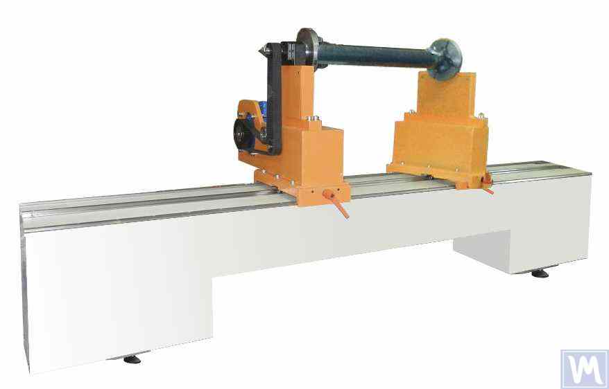
Figure 8. Balancing Machine for Driveshafts up to 2 Meters Long, Weighing up to 500 kg
The model has 2 stands and allows balancing in 2 correction planes.
Balancing Machine for Driveshafts up to 4200 mm Long, Weighing up to 400 kg
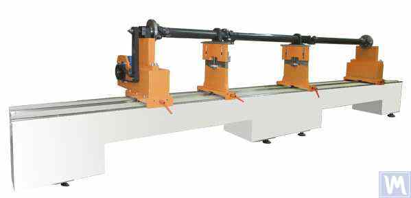
Figure 9. Balancing Machine for Driveshafts up to 4200 mm Long, Weighing up to 400 kg
The model has 4 stands and allows balancing in 4 correction planes simultaneously.
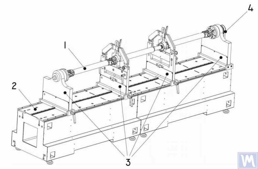
Figure 10. Horizontal Hard Bearing Balancing Machine for Dynamic Balancing of Driveshafts
1 – Balancing item (driveshaft); 2 – Machine base; 3 – Machine supports; 4 – Machine drive; The structural elements of the machine supports are shown in Figure 9.
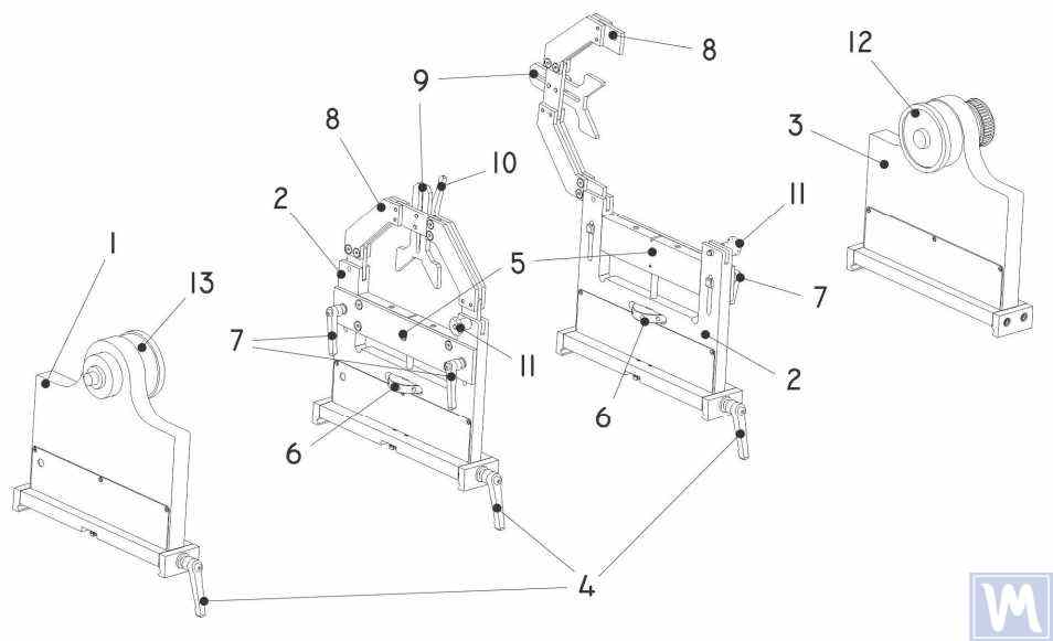
Figure 11. Machine Support Elements for Dynamic Balancing of Driveshafts
1 – Left non-adjustable support; 2 – Intermediate adjustable support (2 pcs.); 3 – Right non-adjustable fixed support; 4 – Support frame lock handle; 5 – Movable support platform; 6 – Support vertical adjustment nut; 7 – Vertical position lock handles; 8 – Support clamping bracket; 9 – Intermediate bearing movable clamp; 10 – Clamp lock handle; 11 – Clamping bracket lock; 12 – Drive (leading) spindle for item installation; 13 – Driven spindle
5. Preparation for Driveshaft Balancing
Below, we will consider the setup of the machine supports and the installation of the balancing item (four-support driveshaft) on the machine supports.
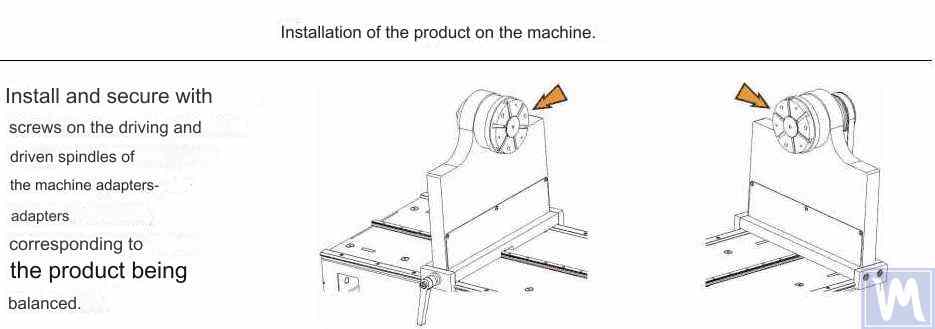
Figure 12. Installation of Transitional Flanges on the Spindles of the Balancing Machine
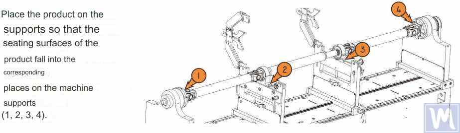
Figure 13. Installation of the Driveshaft on the Supports of the Balancing Machine
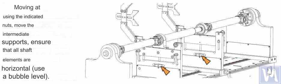
Figure 14. Leveling the Driveshaft Horizontally on the Supports of the Balancing Machine Using a Bubble Level
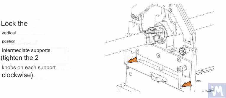
Figure 15. Fixing the Intermediate Supports of the Balancing Machine to Prevent Vertical Displacement of the Driveshaft
Rotate the item manually for a full turn. Ensure that it rotates freely and without jamming on the supports. After this, the mechanical part of the machine is set up, and the item installation is complete.
6. Driveshaft Balancing Procedure
The process of driveshaft balancing on the balancing machine will be considered using the Balanset-4 measuring system as an example. The Balanset-4 is a portable balancing kit designed for balancing in one, two, three, and four correction planes of rotors, either rotating in their own bearings or mounted on a balancing machine. The device includes up to four vibration sensors, a phase angle sensor, a four-channel measuring unit, and a portable computer.
The entire balancing process, including measurement, processing, and display of information on the magnitude and location of corrective weights, is performed automatically and does not require the user to have additional skills and knowledge beyond the provided instructions. The results of all balancing operations are saved in the Balancing Archive and can be printed as reports if necessary. In addition to balancing, the Balanset-4 can also be used as a regular vibro-tachometer, allowing measurement on four channels of the root mean square (RMS) value of total vibration, RMS of the rotational component of vibration, and control of rotor rotation frequency.
Furthermore, the device allows displaying graphs of the time function and vibration spectrum by vibration velocity, which can be useful in assessing the technical condition of the balanced machine.

Figure 16. External View of the Balanset-4 Device for Use as a Measuring and Computing System of the Driveshaft Balancing Machine
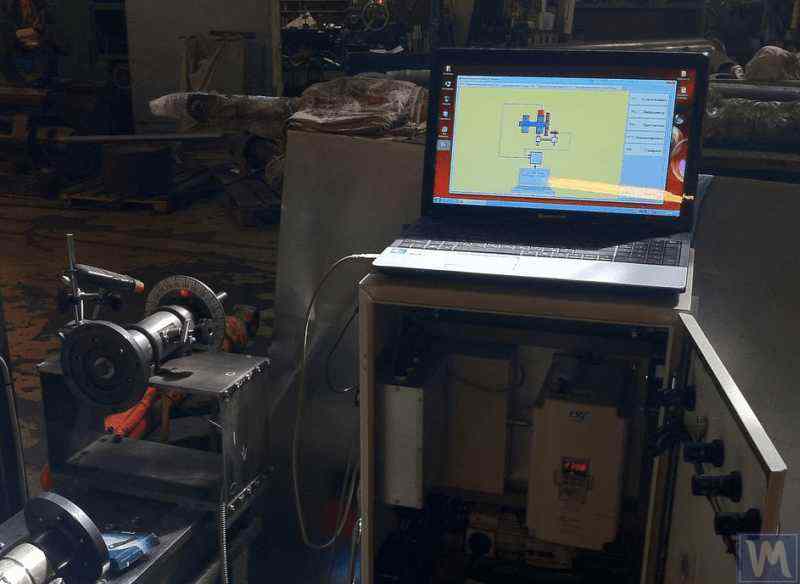
Figure 17. Example of Using the Balanset-4 Device as a Measuring and Computing System of the Driveshaft Balancing Machine
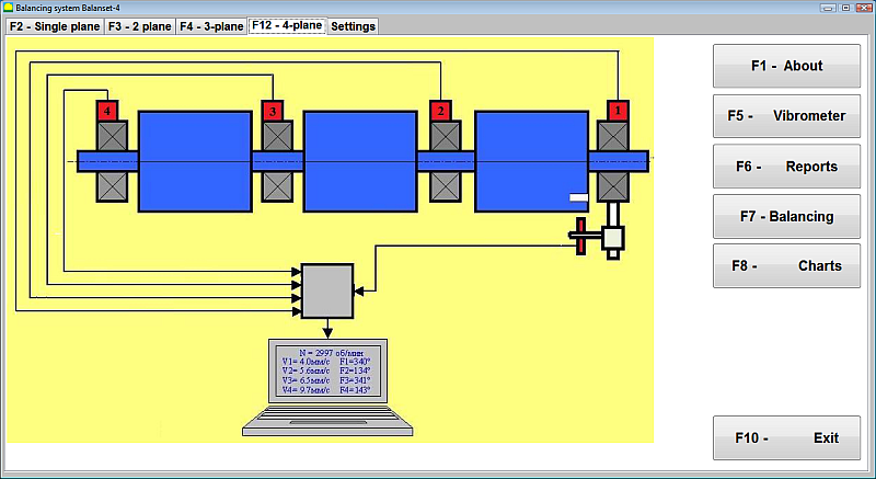
Figure 18. User Interface of the Balanset-4 Device
ניתן לצייד את מכשיר Balanset-4 בשני סוגי חיישנים - מדי תאוצה של רטט למדידת רטט (תאוצת רטט) וחיישני כוח. חיישני רטט משמשים להפעלה במכונות איזון מסוג פוסט-רזוננס, בעוד שחיישני כוח משמשים למכונות מסוג קדם-רזוננס.
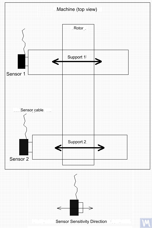
איור 19. התקנה של חיישני רטט Balanset-4 על התומכים של מכונת האיזון
כיוון ציר הרגישות של החיישנים צריך להתאים לכיוון תזוזת הרטט של התמיכה, במקרה זה - אופקי. למידע נוסף על התקנת חיישנים, ראה איזון רוטורים בתנאי הפעלה. התקנת חיישני כוח תלויה בתכונות התכנון של המכונה.
- התקן חיישני רעידות 1, 2, 3, 4 על התומכים של מכונת האיזון.
- חבר את חיישני הרטט למחברים X1, X2, X3, X4.
- התקן את חיישן זווית הפאזה (מד טכומטר לייזר) 5 כך שהפער הנומינלי בין המשטח הרדיאלי (או הקצה) של הרוטור המאוזן לבין בית החיישן יהיה בטווח של 10 עד 300 מ"מ.
- חברו למשטח הרוטור סימן סרט מחזיר אור ברוחב של 10-15 מ"מ לפחות.
- חבר את חיישן זווית הפאזה למחבר X5.
- חבר את יחידת המדידה ליציאת ה-USB של המחשב.
- בעת שימוש בחשמל, חבר את המחשב ליחידת אספקת החשמל.
- חבר את יחידת אספקת החשמל לרשת 220 וולט, 50 הרץ.
- הפעל את המחשב ובחר בתוכנית "BalCom-4".
- לחץ על כפתור "F12-four-plane" (או על מקש הפונקציה F12 במקלדת המחשב) כדי לבחור במצב למדידת רטט בו זמנית בארבעה מישורים באמצעות חיישני רטט 1, 2, 3, 4, המחוברים בהתאמה לכניסות X1, X2 , X3 ו-X4 של יחידת המדידה.
- תרשים מנמוני הממחיש את תהליך מדידת הרטט בו זמנית בארבעה ערוצי מדידה (או תהליך האיזון בארבעה מישורים) מופיע על תצוגת המחשב, כפי שמוצג באיור 16.
לפני ביצוע איזון, מומלץ לבצע מדידות במצב ויברומטר (כפתור F5).
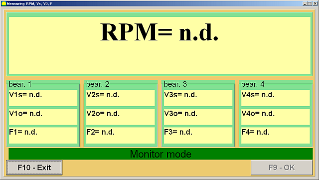
איור 20. מדידות מצב ויברומטר
אם גודל התנודה הכולל V1s (V2s) תואם בקירוב לגודל הרכיב הסיבובי V1o (V2o), ניתן להניח שהתרומה העיקרית לתנודת המנגנון נובעת מחוסר איזון ברוטור. אם גודל התנודה הכולל V1s (V2s) עולה באופן משמעותי על הרכיב הסיבובי V1o (V2o), מומלץ לבדוק את המנגנון - לבדוק את מצב המיסבים, לוודא הרכבה בטוחה על היסוד, לוודא שהרוטור אינו נוגע בחלקים נייחים במהלך הסיבוב, ולשקול את השפעת התנודות ממנגנונים אחרים וכו'.
לימוד גרפי פונקציית הזמן וספקטרום הרטט המתקבלים במצב "ניתוח גרפים-ספקטרלי" יכול להיות שימושי כאן.
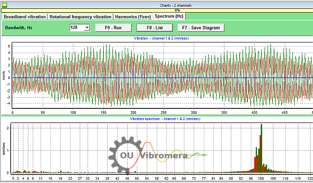
איור 21. פונקציית זמן רטט וגרפים ספקטרום
הגרף מראה באילו תדרים רמות הרטט הן הגבוהות ביותר. אם תדרים אלה שונים מתדר הסיבוב של הרוטור של המנגנון המאוזן, יש צורך לזהות את מקורות רכיבי הרטט הללו ולנקוט צעדים לביטולם לפני האיזון.
חשוב לשים לב גם ליציבות הקריאות במצב ויברומטר - המשרעת והפאזה של הרטט לא אמורים להשתנות ביותר מ-10-15% במהלך המדידה. אחרת, המנגנון עשוי לפעול ליד אזור תהודה. במקרה זה, יש להתאים את מהירות הרוטור.
בעת ביצוע איזון ארבעה מישורים במצב "ראשי", נדרשות חמש ריצות כיול ולפחות ריצת אימות אחת של המכונה המאוזנת. מדידת רעידות במהלך הריצת המכונה הראשונה ללא משקולת ניסיון מתבצעת בסביבת העבודה "איזון ארבעה מישורים". הריצות הבאות מתבצעות עם משקולת ניסיון, המותקנת ברצף על גל ההינע בכל מישור תיקון (באזור כל תומך של מכונת איזון).
לפני כל ריצה שלאחר מכן, יש לבצע את הצעדים הבאים:
- עצור את סיבוב הרוטור של המכונה המאוזנת.
- הסר את משקל הניסיון שהותקן קודם לכן.
- התקן את משקל הניסיון במטוס הבא.
איור 23. אזור עבודה באיזון ארבעה מישורים
לאחר השלמת כל מדידה, תוצאות תדר הסיבוב של הרוטור (Nob), כמו גם ערכי RMS (Vo1,Vo2,Vo3,Vo4) והשלבים (F1, פ2, פ3, פ4) של הרטט בתדר הסיבוב של הרוטור המאוזן נשמרים בשדות המתאימים בחלון התוכנית. לאחר הריצה החמישית (משקל במישור 4), מופיעה סביבת העבודה "משקולות איזון" (ראה איור 24), המציגה את הערכים המחושבים של המסות (M1, M2, M3, M4) וזוויות ההתקנה (ו1, ו2, ו3, ו4) של המשקולות המתקנות שצריך להתקין על הרוטור בארבעה מישורים כדי לפצות על חוסר האיזון שלו.
איור 24. סביבת עבודה עם פרמטרים מחושבים של משקולות מתקנות בארבעה מישורים
תשומת הלב! לאחר השלמת תהליך המדידה במהלך הריצה החמישית של המכונה המאוזנת, יש צורך לעצור את סיבוב הרוטור ולהסיר את משקולת הניסיון שהותקנה קודם לכן. רק לאחר מכן ניתן להמשיך בהתקנה (או הסרה) של משקולות התיקון על הרוטור.
המיקום הזוויתי להוספה (או הסרה) של המשקל המתקן על הרוטור במערכת הקואורדינטות הקוטביות נמדד ממיקום התקנת משקולת הניסיון. כיוון מדידת הזווית תואם את כיוון הסיבוב של הרוטור. במקרה של איזון באמצעות להבים, להב הרוטור המאוזן, הנחשב בתנאי כלהב הראשון, תואם את מיקום התקנת משקולת הניסיון. כיוון המספור של הלהבים המצוין על צג המחשב עוקב אחר כיוון הסיבוב של הרוטור.
בגרסה זו של התוכנית, ההנחה היא כברירת מחדל שמשקל התיקון יתווסף לרוטור. הדבר מצוין על ידי הסימון שנקבע בשדה "הוסף". אם יש צורך לתקן את חוסר האיזון על ידי הסרת המשקל (למשל, על ידי קידוח), יש להגדיר את הסימון בשדה "הסר" באמצעות העכבר, ולאחר מכן המיקום הזוויתי של המשקל המתקן ישתנה אוטומטית ב-180 מעלות.
לאחר התקנת משקולות התיקון על הרוטור המאוזן, לחצו על כפתור "יציאה – F10" (או על מקש הפונקציה F10 במקלדת המחשב) כדי לחזור לסביבת העבודה הקודמת של "איזון ארבעת המישורים" ולבדוק את יעילות פעולת האיזון. לאחר השלמת ריצת האימות, תוצאות תדירות הסיבוב של הרוטור (Nob) וערכי RMS (Vo1,Vo2,Vo3,Vo4) ושלבים (F1, פ2, פ3, פ4) של הרטט בתדר הסיבוב של הרוטור המאוזן נשמרים. במקביל, מרחב העבודה "משקולות איזון" (ראה איור 21) מופיע מעל מרחב העבודה "איזון ארבע-מישורי", ומציג את הפרמטרים המחושבים של משקולות תיקון נוספות שיש להתקין (או להסיר) על הרוטור כדי לפצות על חוסר האיזון השיורי שלו. בנוסף, מרחב עבודה זה מציג את ערכי חוסר האיזון השיורי שהושג לאחר האיזון. אם ערכי הרטט השיורי ו/או חוסר האיזון השיורי של הרוטור המאוזן עומדים בדרישות הסבילות שצוינו בתיעוד הטכני, ניתן להשלים את תהליך האיזון. אחרת, ניתן להמשיך את תהליך האיזון. שיטה זו מאפשרת תיקון שגיאות אפשריות באמצעות קירובים עוקבים שעלולים להתרחש בעת התקנה (הסרה) של המשקולת המתקנת על הרוטור המאוזן.
אם תהליך האיזון נמשך, יש להתקין (או להסיר) משקולות תיקון נוספות על הרוטור המאוזן בהתאם לפרמטרים שצוינו בסביבת העבודה "משקולות איזון".
כפתור "מקדמים – F8" (או מקש הפונקציה F8 במקלדת המחשב) משמש לצפייה ושמירה בזיכרון המחשב של מקדמי איזון הרוטור (מקדמי השפעה דינמיים) המחושבים מתוצאות חמשת פעולות הכיול.
7. Recommended Balancing Accuracy Classes for Rigid Rotors
טבלה 2. שיעורי דיוק איזון מומלצים עבור רוטורים קשיחים.

שיעורי דיוק איזון מומלצים לרוטורים קשיחים
| סוגי מכונות (רוטורים) | דרגת דיוק איזון | ערך eper Ω mm/s |
|---|---|---|
| גלי ארכובה הנעה (בלתי מאוזנים מבחינה מבנית) עבור מנועי דיזל ימיים גדולים במהירות נמוכה (מהירות בוכנה פחות מ-9 מ"ש) | G 4000 | 4000 |
| גלי ארכובה הנעה (מאוזנים מבנית) עבור מנועי דיזל ימיים גדולים במהירות נמוכה (מהירות בוכנה פחות מ-9 מ"ש) | G 1600 | 1600 |
| הניע גל ארכובה (לא מאוזן מבחינה מבנית) על מבודדי רעידות | G 630 | 630 |
| הניע גל ארכובה (לא מאוזן מבחינה מבנית) על תומכים קשיחים | G 250 | 250 |
| מנועי הדדיות המורכבים למכוניות נוסעים, משאיות וקטרים | G 100 | 100 |
| חלקי חילוף לרכב: גלגלים, חישוקי גלגלים, ערכות גלגלים, הילוכים | ||
| הניע גל ארכובה (מאוזן מבני) על מבודדי רעידות | G 40 | 40 |
| מכונות חקלאיות | G 16 | 16 |
| הניע גל ארכובה (מאוזן) על תומכים קשיחים | ||
| מגרסה | ||
| פירי הנעה (גלי הנעה, פירי ברגים) | ||
| טורבינות גז למטוסים | G 6.3 | 6.3 |
| צנטריפוגות (מפרידים, מתנחלים) | ||
| מנועים חשמליים וגנרטורים (עם גובה פיר של לפחות 80 מ"מ) עם מהירות סיבוב נומינלית מקסימלית של עד 950 דקות-1 | ||
| מנועים חשמליים עם גובה פיר של פחות מ-80 מ"מ | ||
| מעריצים | ||
| כונני הילוכים | ||
| מכונות לשימוש כללי | ||
| מכונות חיתוך מתכת | ||
| מכונות לייצור נייר | ||
| משאבות | ||
| מגדשי טורבו | ||
| טורבינות מים | ||
| מדחסים | ||
| כוננים נשלטי מחשב | G 2.5 | 2.5 |
| מנועים חשמליים וגנרטורים (עם גובה פיר של לפחות 80 מ"מ) עם מהירות סיבוב נומינלית מקסימלית מעל 950 דקות-1 | ||
| טורבינות גז וקיטור | ||
| כונני מכונות חיתוך מתכת | ||
| מכונות טקסטיל | ||
| כונני ציוד אודיו ווידאו | G 1 | 1 |
| כונני מכונות גריסה | ||
| צירים והנעים של ציוד בעל דיוק גבוה | G 0.4 | 0.4 |
שאלות נפוצות על איזון גל הינע
מהו איזון ציר ההינע?
איזון גל ההינע הוא תהליך של תיקון כל חוסר איזון במסה בגל ההינע כך שיסתובב בצורה חלקה מבלי לגרום לרעידות. זה כרוך במדידת היכן הגל כבד יותר בצד אחד ולאחר מכן הוספה או הסרה של כמויות קטנות של משקל (לדוגמה, ריתוך על משקולות איזון) כדי לנטרל את חוסר האיזון הזה. גל הינע מאוזן פועל באופן שווה, מה שמונע רעידות מוגזמות ובלאי של רכיבי הרכב.
מדוע איזון גל ההינע חשוב?
גל הנעה לא מאוזן יכול להוביל לתנודות חזקות, במיוחד במהירויות מסוימות, ועלול לגרום לרעשי נקישה במהלך האצה או החלפת הילוכים. עם הזמן, תנודות אלו עלולות לפגוע במסבים, במפרקים אוניברסליים וברכיבים אחרים של מערכת ההינע. איזון גל ההינע מבטל את התנודות הללו, מבטיח נסיעה חלקה יותר, מפחית את העומס על החלקים ומונע נזק יקר או זמן השבתה.
מהם התסמינים הנפוצים של גל הינע לא מאוזן?
התסמינים האופייניים של גל הינע לא מאוזן או פגום כוללים רטט מורגש או רעידות ברצפת הרכב או במושב, במיוחד ככל שהמהירות עולה. ייתכן שתשמעו גם קולות נקישה או רטטו בעת העברת הילוכים או במהלך האצה והאטה. במקרים מסוימים, המפרק האוניברסלי עלול להתחמם יתר על המידה עקב חוסר איזון. אם אתם מבחינים בסימנים אלה, סביר להניח שגל ההינע זקוק לאיזון או תיקון.
איך מאזנים גל הינע?
איזון גל ההינע מתבצע בדרך כלל באמצעות מכונת איזון ייעודית. גל ההינע מורכב ומסובב במהירות גבוהה בעוד חיישנים מזהים כל חוסר איזון. לאחר מכן, טכנאי מצמיד משקולות קטנות לגל ההינע (או מסיר חומר) במיקומים ספציפיים בהתבסס על קריאות המכונה. תהליך זה חוזר על עצמו עד שגל ההינע מסתובב ללא רעידות משמעותיות. מערכות מודרניות כמו Balanset-4 יכולות להנחות תהליך זה ולחשב בדיוק היכן וכמה משקל להוסיף לאיזון מדויק.
סיכום
לסיכום, איזון נכון של גל ההינע חיוני לבטיחות, ביצועים וחיסכון בעלויות. על ידי זיהוי ותיקון חוסר איזון, אתם מונעים בלאי מיותר של חלקים, נמנעים מתקלות מזיקות ושומרים על ביצועי מכונה אופטימליים. מערכות איזון מודרניות כמו מכשירי Balanset-1 ו-Balanset-4 שלנו הופכות את התהליך ליעיל, ועוזרות אפילו לסדנאות קטנות להשיג תוצאות מקצועיות.
אם אתם מתמודדים עם רעידות מתמשכות בגל ההינע או זקוקים לפתרון איזון אמין, אל תהססו לפעול. יש ליישם את השלבים המפורטים במדריך זה או להתייעץ עם המומחים שלנו לקבלת סיוע. בעזרת הגישה והציוד הנכונים, תוכלו להבטיח שגל ההינע שלכם יפעל בצורה חלקה ואמינה במשך שנים רבות. צרו קשר למידע נוסף או לחקור את ציוד איזון גל ההינע הטוב ביותר לצרכים שלך.

0 תגובות