ಸಮತೋಲನ ಸೇವೆಗಳು › ಅಭಿಮಾನಿಗಳು › ಎಕ್ಸ್ಹಾಸ್ಟರ್ಗಳು & ಡ್ರಾಫ್ಟ್ ಫ್ಯಾನ್ಗಳು
ಎಕ್ಸ್ಹಾಸ್ಟರ್ & ಇಂಡ್ಯೂಸ್ಡ್-ಡ್ರಾಫ್ಟ್ ಫ್ಯಾನ್ ಬ್ಯಾಲೆನ್ಸಿಂಗ್ — ಇನ್-ಸಿಟು, ಕಾರ್ಯಾಚರಣಾ ವೇಗದಲ್ಲೇ
ಎಕ್ಸ್ಹಾಸ್ಟರ್ಗಳು, ಧೂಳು ಎಕ್ಸ್ಟ್ರಾಕ್ಟರ್ಗಳು ಮತ್ತು ಇಂಡ್ಯೂಸ್ಡ್-ಡ್ರಾಫ್ಟ್ ಫ್ಯಾನ್ಗಳು ಅತ್ಯಂತ ಕಠಿಣ ಪ್ರೊಸೆಸ್ ಪರಿಸರಗಳಲ್ಲಿ ಕಾರ್ಯನಿರ್ವಹಿಸುತ್ತವೆ — ಬ್ಲೇಡ್ಗಳನ್ನು ನಿರಂತರವಾಗಿ ಅರಿಗೊಳಿಸಿ ಅಸಮಮಿತ ಜಮಾವಣೆಗಳನ್ನು ರೂಪಿಸುವ ಘರ್ಷಣಾತ್ಮಕ, ಬಿಸಿ ಅಥವಾ ಕರೋಸಿವ್ ಅನಿಲ ಹರಿವನ್ನು ಹಸ್ತಾಂತರಿಸುತ್ತವೆ. ನಾವು ಮೃದುವಾದ ಕಾರ್ಯಾಚರಣೆಯನ್ನು ಮರುಸ್ಥಾಪಿಸುತ್ತೇವೆ ಸ್ಥಳದಲ್ಲಿ, ಕಾರ್ಯಾಚರಣೆ ವೇಗದಲ್ಲಿ, ಇಂಪೆಲ್ಲರ್ನ್ನು ಬೇರ್ಪಡಿಸದೆ ಅಥವಾ ಡಕ್ಟ್ವರ್ಕ್ ಸಂಪರ್ಕವನ್ನು ಕಡಿತಗೊಳಿಸದೆ — ಒಂದೇ ಆನ್-ಸೈಟ್ ಸೆಷನ್ನಲ್ಲಿ ಬೇಯರಿಂಗ್ ವೈಫಲ್ಯ ಮತ್ತು ಸಂರಚನಾ ದಣಿವಿನ ಪ್ರಮುಖ ಕಾರಣವನ್ನು ನಿವಾರಿಸುತ್ತೇವೆ.
ಸಂಕ್ಷಿಪ್ತವಾಗಿ: ಎಕ್ಸ್ಹಾಸ್ಟರ್ ಮತ್ತು ಇಂಡ್ಯೂಸ್ಡ್-ಡ್ರಾಫ್ಟ್ ಫ್ಯಾನ್ ಬ್ಯಾಲೆನ್ಸಿಂಗ್ ಅನ್ನು ಇನ್-ಸಿಟುವಾಗಿ, ಸಾಮಾನ್ಯ ಕಾರ್ಯಾಚರಣಾ ವೇಗದಲ್ಲೇ, influence-coefficient ವಿಧಾನವನ್ನು ಬಳಸಿ ಮಾಡಲಾಗುತ್ತದೆ. ಬೇಯರಿಂಗ್ ಹೌಸಿಂಗ್ ಮೇಲಿನ ಕಂಪನ ಅಕ್ಸೆಲರೋಮೀಟರ್ ಮತ್ತು ಶಾಫ್ಟ್ ಮೇಲಿನ ಲೇಸರ್ ಟ್ಯಾಕೋಮೀಟರ್ ಪ್ರಸ್ತುತ ಅಸಮತೋಲನ ಸ್ಥಿತಿಯನ್ನು ಅಳೆಯುತ್ತವೆ; Balanset-1A ನಿಖರ ತಿದ್ದುಪಡಿ ಭಾರ ಮತ್ತು ಕೋಣವನ್ನು ಲೆಕ್ಕಿಸುತ್ತದೆ. ಇಂಪೆಲ್ಲರ್ ತೆಗೆದುಹಾಕುವುದು ಬೇಡ, ಡಕ್ಟ್ ಬೇರ್ಪಡಿಸುವುದು ಬೇಡ — ಸಾಮಾನ್ಯ ಸಿಂಗಲ್-ಪ್ಲೇನ್ ಕೆಲಸ ಒಂದು ಗಂಟೆಯೊಳಗೆ ಪೂರ್ಣಗೊಳ್ಳುತ್ತದೆ, ಕಂಪನವನ್ನು 70 % ಅಥವಾ ಅದಕ್ಕಿಂತ ಹೆಚ್ಚು ಕಡಿಮೆ ಮಾಡುತ್ತದೆ ಮತ್ತು ಬೇಯರಿಂಗ್ ಸೇವಾ ಆಯುಷ್ಯವನ್ನು ಎಂಟರಿಂದ ಹತ್ತು ಪಟ್ಟು ಹೆಚ್ಚಿಸುತ್ತದೆ. ಅರಿಕೆ ಮತ್ತು ಜಮಾವಣೆಯಿಂದ ಉಂಟಾಗುವ ಮರು-ಅಸಮತೋಲನವನ್ನು ಅದೇ ಭೇಟಿ ಅಂತರದಲ್ಲೇ ಯಾವುದೇ ವರ್ಕ್ಶಾಪ್ ಸಹಾಯವಿಲ್ಲದೆ ಪುನಃ ತಿದ್ದುಪಡಿಸಬಹುದು.
ನಿಮ್ಮ ಎಕ್ಸ್ಹಾಸ್ಟರ್ ಅಥವಾ ಡ್ರಾಫ್ಟ್ ಫ್ಯಾನ್ ಅಸಮತೋಲನಗೊಂಡಿದೆ ಎಂಬ ಸೂಚನೆಗಳು
ಸಮತೋಲನ ಕಳೆದುಕೊಂಡಿರುವ ಎಕ್ಸ್ಹಾಸ್ಟರ್ಗಳು ಮತ್ತು ID ಫ್ಯಾನ್ಗಳು ಯಂತ್ರದ ಆರೋಗ್ಯ ಕುಸಿಯುತ್ತಿರುವುದು ಸ್ಪಷ್ಟವಾಗುವ ಮಾದರಿಯನ್ನು ತೋರಿಸುತ್ತವೆ. ಈ ಲಕ್ಷಣಗಳಲ್ಲಿ ಯಾವುದಾದರೂ ಒಂದು ಕಂಪನ ಮಾಪನಕ್ಕೆ ಸಮರ್ಥನೆ ನೀಡುತ್ತದೆ, ಮತ್ತು 1× RPM ಘಟಕ ಪ್ರಾಬಲ್ಯದಲ್ಲಿದ್ದರೆ ಇನ್-ಸಿಟು ಬ್ಯಾಲೆನ್ಸಿಂಗ್ ಸೆಷನ್ ಅಗತ್ಯವಾಗುತ್ತದೆ:
ಎಕ್ಸ್ಹಾಸ್ಟರ್ಗಳು & ಡ್ರಾಫ್ಟ್ ಫ್ಯಾನ್ಗಳು ಏಕೆ ಅಸಮತೋಲನಗೊಳ್ಳುತ್ತವೆ — ಮತ್ತು ಅದರ ವೆಚ್ಚ ಏನು
ಎಕ್ಸ್ಹಾಸ್ಟರ್ಗಳು ಮತ್ತು ಇಂಡ್ಯೂಸ್ಡ್-ಡ್ರಾಫ್ಟ್ ಫ್ಯಾನ್ಗಳನ್ನು ಪ್ರೊಸೆಸ್ ಹರಿವಿನ ಮಲಿನ, ಘರ್ಷಣಾತ್ಮಕ ಅಥವಾ ರಾಸಾಯನಿಕವಾಗಿ ಆಕ್ರಮಕ ಭಾಗ ಹರಿಯುವ ಸ್ಥಳದಲ್ಲೇ ಇಡಲಾಗುತ್ತದೆ — ಅಂದರೆ ಅವುಗಳ ಇಂಪೆಲ್ಲರ್ಗಳು ನಿರಂತರ ದಾಳಿಯಲ್ಲಿರುತ್ತವೆ. ಫ್ಲೈ-ಆಶ್, ಕ್ಲಿಂಕರ್ ಧೂಳು ಮತ್ತು ಖನಿಜ ಕಣಗಳು ಬ್ಲೇಡ್ಗಳನ್ನು ಅಸಮಮಿತವಾಗಿ ಅರಿಗೊಳಿಸಿ, ಒಂದು ವಿಭಾಗದಿಂದ ಇನ್ನೊಂದಕ್ಕಿಂತ ಹೆಚ್ಚು ವಸ್ತುವನ್ನು ತೆಗೆದುಹಾಕುತ್ತವೆ. ಸ್ಕೇಲ್, ಟಾರ್ ಮತ್ತು ಅಂಟಿಕೊಳ್ಳುವ ಕಣಗಳು ಬ್ಲೇಡ್ ಮುಖಗಳು ಮತ್ತು ಇಂಪೆಲ್ಲರ್ ಡಿಸ್ಕ್ ಮೇಲೆ ಊಹಿಸಲಾಗದ ರೀತಿಯಲ್ಲಿ ಜಮೆಯಾಗುತ್ತವೆ. ನಿರ್ವಹಣೆ ವೇಳೆ ಅಳವಡಿಸುವ ರಕ್ಷಕ wear linerಗಳು ಅಥವಾ ವೆಲ್ಡ್ hard-facing ಸ್ಥಳೀಯ ಭಾರವನ್ನು ಹೆಚ್ಚಿಸುತ್ತವೆ. ಕರೋಷನ್ ಕೆಲವು ನಿರ್ದಿಷ್ಟ ಬ್ಲೇಡ್ಗಳು ಅಥವಾ ವಿಭಾಗಗಳನ್ನು ಇತರಕ್ಕಿಂತ ವೇಗವಾಗಿ ಹಾಳುಮಾಡುತ್ತದೆ. ಸ್ಟಾರ್ಟ್-ಅಪ್ ಮತ್ತು ಶಟ್ಡೌನ್ ಚಕ್ರಗಳಲ್ಲಿ ಉಂಟಾಗುವ ಥರ್ಮಲ್ ವಿಕೃತಿ ರೋಟರ್ ವಿಸ್ತರಿಸಿ ಕುಗ್ಗುವಾಗ ಭಾರಕೇಂದ್ರವನ್ನು ಸ್ಥಳಾಂತರಿಸಬಹುದು.
ಈ ಪ್ರತಿಯೊಂದು ಕ್ರಮಣವೂ ಭಾರಕೇಂದ್ರವನ್ನು ಜ್ಯಾಮಿತೀಯ ಭ್ರಮಣ ಅಕ್ಷದಿಂದ ದೂರ ಸರಿಸುತ್ತದೆ. ಕೇಂದ್ರಭ್ರಮಣ ಬಲವು ವರ್ಗ ಭ್ರಮಣ ವೇಗದ ವರ್ಗದಂತೆ ಹೆಚ್ಚಾಗುವುದರಿಂದ, ಬ್ಲೇಡ್ ಟಿಪ್ನಲ್ಲಿ ಕೇವಲ 50 g ಭಾರ ಆಫ್ಸೆಟ್ ಇದ್ದರೂ 750–1,500 rpm ಕೈಗಾರಿಕಾ ಫ್ಯಾನ್ ವೇಗಗಳಲ್ಲಿ ಹಲವು ಕಿಲೋನ್ಯೂಟನ್ಗಳ ಡೈನಾಮಿಕ್ ರೇಡಿಯಲ್ ಲೋಡ್ ಉಂಟಾಗುತ್ತದೆ — ಹೆಚ್ಚಿನ ವೇಗಗಳಲ್ಲಿ ಇನ್ನೂ ಹೆಚ್ಚಾಗುತ್ತದೆ.
ಪ್ಲಾಂಟ್ ಇಂಜಿನಿಯರ್ಗಳಿಗೆ ಇದರ ಆರ್ಥಿಕ ಹೊರೆ ಚೆನ್ನಾಗಿ ಗೊತ್ತಿದೆ: ತುರ್ತು ಬೇಯರಿಂಗ್ ಬದಲಾವಣೆಗಾಗಿ ಅನಿಯೋಜಿತ ಶಟ್ಡೌನ್ಗಳು, ದೊಡ್ಡ ಹಾಟ್-ಗ್ಯಾಸ ಫ್ಯಾನ್ಗಳಿಗೆ ಪ್ರವೇಶಿಸಲು ಕಾರ್ಮಿಕ ಮತ್ತು ಕ್ರೇನ್ ಸಮಯ, ಕಡಿಮೆಯಾದ ಡ್ರಾಫ್ಟ್ ಸಾಮರ್ಥ್ಯ, ಹೆಚ್ಚಿದ ನಿರ್ದಿಷ್ಟ ಶಕ್ತಿ ಬಳಕೆ, ಮತ್ತು ಕೊನೆಗೆ ಇಂಪೆಲ್ಲರ್ ಡಿಸ್ಕ್ ಅಥವಾ ಶಾಫ್ಟ್ಗೆ ಸಂರಚನಾ ಹಾನಿ. ಅವಧಿಪರ ಇನ್-ಸಿಟು ಬ್ಯಾಲೆನ್ಸಿಂಗ್ — ಸಾಮಾನ್ಯವಾಗಿ ಒಂದು ಗಂಟೆಯೊಳಗೆ ಪೂರ್ಣಗೊಳ್ಳುತ್ತದೆ — ಮೂಲದಲ್ಲೇ ಡೈನಾಮಿಕ್ ಲೋಡ್ ಅನ್ನು ಕಡಿತಗೊಳಿಸಿ, ದೊಡ್ಡ ನಿರ್ವಹಣಾ ಹಸ್ತಕ್ಷೇಪಗಳ ನಡುವೆ ಇರುವ ಅವಧಿಯನ್ನು ಗಮನಾರ್ಹವಾಗಿ ವಿಸ್ತರಿಸುತ್ತದೆ.
ಕಂಪನವನ್ನು ಅರ್ಧೇಕ ಮಾಡುವುದು ಬೀರಿಂಗ್ ಆಯುಶ್ಯನನ್ನು ಗುಣಿಸುವುದು ಏಕೆ
ನಾವು ಎಕ್ಸ್ಹಾಸ್ಟರ್ನ್ನು ಹೇಗೆ ಬ್ಯಾಲೆನ್ಸ್ ಮಾಡುತ್ತೇವೆ — ಹಂತ ಹಂತವಾಗಿ
Balanset-1A ಬಳಸಿ ಮಾಡುವ ಫೀಲ್ಡ್ ಬ್ಯಾಲೆನ್ಸಿಂಗ್ influence-coefficient ವಿಧಾನವನ್ನು ಅನುಸರಿಸುತ್ತದೆ — ರೋಟರ್ ಜ್ಯಾಮಿತಿ, ಪ್ರೊಸೆಸ್ ತಾಪಮಾನ ಅಥವಾ ಧೂಳು ಲೋಡ್ ಏನೇ ಇರಲಿ ಕೆಲಸ ಮಾಡುವ ಅದೇ ಕ್ರಮಬದ್ಧ ವಿಧಾನ:
- ಸಂವೇದಕಗಳನ್ನು ಮೌಂಟ್ ಮಾಡಿ. ಕಂಪನ ಅಕ್ಸೆಲರೋಮೀಟರ್ನ್ನು ಚುಂಬಕದ ಮೂಲಕ ಬೇಯರಿಂಗ್ ಹೌಸಿಂಗ್ಗೆ ಅಳವಡಿಸಲಾಗುತ್ತದೆ ಮತ್ತು ಲೇಸರ್ ಟ್ಯಾಕೋಮೀಟರ್ನ್ನು ಶಾಫ್ಟ್ ಅಥವಾ ಇಂಪೆಲ್ಲರ್ ಹಬ್ ಮೇಲಿನ ಪ್ರತಿಫಲಕ ಪಟ್ಟಿಗೆ ಗುರಿಮಾಡಲಾಗುತ್ತದೆ. ಡಿಸಅಸೆಂಬ್ಲಿ ಅಗತ್ಯವಿಲ್ಲ — ಫ್ಯಾನ್ ಇಡೀ ಪ್ರಕ್ರಿಯೆಯಲ್ಲೂ ಸಾಮಾನ್ಯ ಪ್ರೊಸೆಸ್ ಪರಿಸ್ಥಿತಿಗಳಲ್ಲೇ ಓಡುತ್ತದೆ. ಸಿಂಗಲ್-ಪ್ಲೇನ್ಗೆ ಒಂದು ಬೇಯರಿಂಗ್ಗೆ ಪ್ರವೇಶ ಸಾಕು; ಎರಡು-ಸಮತಲ ತಿದ್ದುಪಡಿಗೆ ಎರಡೂ ತುದಿ ಬೇಯರಿಂಗ್ಗಳಿಗೆ ಪ್ರವೇಶ ಅಗತ್ಯ.
- ಮೂಲ ಅಳತೆಯನ್ನು ಪಡೆಯಿರಿ. ಪೂರ್ಣ ಕಾರ್ಯಾಚರಣಾ ವೇಗದ ಒಂದು ರನ್ 1× RPM ನಲ್ಲಿ ಕಂಪನ ಆಂಪ್ಲಿಟ್ಯೂಡ್ ಮತ್ತು ಫೇಸ್ ಕೋಣವನ್ನು ದಾಖಲಿಸಿ, ಅಸಮತೋಲನದ ಪ್ರಸ್ತುತ ಪ್ರಮಾಣ ಮತ್ತು ದಿಕ್ಕನ್ನು ಸ್ಥಾಪಿಸುತ್ತದೆ.
- ಪರೀಕ್ಷೆಯ ತೂಕವನ್ನು ಸೇರಿಸಿ. ತಿಳಿದಿರುವ ಪರೀಕ್ಷಾ ಭಾರವನ್ನು ದಾಖಲಾಗಿದ ಕೋಣೀಯ ಸ್ಥಾನದಲ್ಲಿ ಇಂಪೆಲ್ಲರ್ ಡಿಸ್ಕ್ ಅಥವಾ ಹಬ್ ಫ್ಲಾಂಜ್ಗೆ ಬೋಲ್ಟ್ ಅಥವಾ ಕ್ಲ್ಯಾಂಪ್ ಮಾಡಲಾಗುತ್ತದೆ. ಎರಡನೇ ರನ್ ಬದಲಾಗಿದ ಕಂಪನ ಪ್ರತಿಕ್ರಿಯೆಯನ್ನು ಸೆರೆಹಿಡಿಯುತ್ತದೆ — ಇದರಿಂದ ಸಾಧನಕ್ಕೆ ತಿದ್ದುಪಡಿ ಗಣನೆಗೆ ಬೇಕಾದ influence coefficient ದೊರೆಯುತ್ತದೆ.
- ಸಾಧನವನ್ನು ಗಣನೆ ಮಾಡುವ ಅವಕಾಶ ನೀಡಿ. Balanset-1A influence-coefficient ಆಲ್ಗೊರಿಥಮ್ ಅನ್ನು ಅನ್ವಯಿಸಿ ನಿಖರ ತಿದ್ದುಪಡಿ ಭಾರ ಮತ್ತು ಕೋಣೀಯ ಸ್ಥಾನವನ್ನು ನೀಡುತ್ತದೆ — ಕಾಂಪ್ಯಾಕ್ಟ್ ಡಿಸ್ಕ್ ಇಂಪೆಲ್ಲರ್ಗಳಿಗೆ ಒಂದು ಸಮತಲ, ಹಾಗೂ ಅಸಮತೋಲನವು ರೋಟರ್ ಉದ್ದದ ಮಟ್ಟಿಗೆ ಹಂಚಿಕೊಂಡಿರುವ ಅಗಲವಾದ ಅಥವಾ ಆಳವಾದ ಇಂಪೆಲ್ಲರ್ಗಳಿಗೆ ಎರಡು ಸಮತಲಗಳು.
- ಸುಧಾರಣೆಯ ತೂಕವನ್ನು ಸ್ಥಿರ ಮಾಡಿ. ಲೆಕ್ಕಿಸಲಾದ ಭಾರವನ್ನು ನಿಗದಿತ ಕೋಣದಲ್ಲಿ ಇಂಪೆಲ್ಲರ್ ಡಿಸ್ಕ್, ಹಬ್ ಫ್ಲಾಂಜ್ ಅಥವಾ ಬ್ಲೇಡ್ ರೂಟ್ ಮೇಲೆ ವೆಲ್ಡ್, ಬೋಲ್ಟ್ ಅಥವಾ ಕ್ಲ್ಯಾಂಪ್ ಮಾಡಲಾಗುತ್ತದೆ. ಜಮಾವಣೆ ಮತ್ತೆ ಸೇರುವಾಗ ಮರುಬ್ಯಾಲೆನ್ಸಿಂಗ್ ವೇಗವಾಗಲು ಶಾಶ್ವತ stud ಸ್ಥಾನಗಳನ್ನು ಮುಂಚಿತವಾಗಿ ಅಳವಡಿಸಬಹುದು.
- ಪರಿಶೀಲಿಸಿ ಮತ್ತು ದಾಖಲೆ ಮಾಡಿ. ಅಂತಿಮ ಮಾಪನ ರನ್ ಉಳಿದ ಅಸಮತೋಲನವು ಫ್ಯಾನ್ನ ಬ್ಯಾಲೆನ್ಸ್ ಗ್ರೇಡ್ಗೆ ಹೊಂದುವ ISO ಸಹಿಷ್ಣುತೆ ಪಟ್ಟಿಯೊಳಗಿದೆ ಎಂದು ದೃಢೀಕರಿಸುತ್ತದೆ. Balanset-1A ನಿರ್ವಹಣಾ ದಾಖಲೆಗೆ ಬ್ಯಾಲೆನ್ಸಿಂಗ್ ವರದಿಯನ್ನು ಉಳಿಸುತ್ತದೆ.
ನಾವು ಸಮತೋಲಿತ ಮಾಡುವುದು
- ಇಂಡ್ಯೂಸ್ಡ್-ಡ್ರಾಫ್ಟ್ (ID) ಬಾಯ್ಲರ್ ಮತ್ತು ಭಟ್ಟಿ ಫ್ಯಾನ್ಗಳು
- ಸಿಮೆಂಟ್ ಮತ್ತು ಖನಿಜ-ಪ್ರಸಂಸ್ಕರಣಾ ಲೈನ್ಗಳಲ್ಲಿನ ಎಕ್ಸ್ಹಾಸ್ಟರ್ ಫ್ಯಾನ್ಗಳು
- ಧೂಳು-ಎಕ್ಸ್ಟ್ರಾಕ್ಷನ್ ಮತ್ತು ಹೊಗೆ-ಎಕ್ಸ್ಟ್ರಾಕ್ಷನ್ ಫ್ಯಾನ್ಗಳು
- ಬ್ಯಾಗ್-ಫಿಲ್ಟರ್ ಎಕ್ಸ್ಹಾಸ್ಟ್ ಫ್ಯಾನ್ಗಳು
- ಕ್ಲಿಂಕರ್ ಕೂಲರ್ ಎಕ್ಸ್ಹಾಸ್ಟ್ ಫ್ಯಾನ್ಗಳು
- ಕೈಗಾರಿಕಾ ಸ್ಪ್ರೇ-ಬೂತ್ ಮತ್ತು ಪೇಂಟ್-ಶಾಪ್ ಎಕ್ಸ್ಹಾಸ್ಟರ್ಗಳು
- ವುಡ್ವರ್ಕಿಂಗ್ ಮತ್ತು ಚಿಪ್-ಕನ್ವೇಯಿಂಗ್ ಎಕ್ಸ್ಹಾಸ್ಟ್ ಫ್ಯಾನ್ಗಳು
- ಹೆಚ್ಚಿನ ತಾಪಮಾನದ ಫ್ಲೂ-ಗ್ಯಾಸ ರಿಸರ್ಕ್ಯುಲೇಷನ್ ಫ್ಯಾನ್ಗಳು
- ಖನಿ ವಾತಾಯನ ಎಕ್ಸ್ಹಾಸ್ಟ್ ಫ್ಯಾನ್ಗಳು
- ಫೋರ್ಸ್ಡ್-ಡ್ರಾಫ್ಟ್ (FD) ಬಾಯ್ಲರ್ ಫ್ಯಾನ್ಗಳು
- ರಾಸಾಯನಿಕ-ಪ್ರೊಸೆಸ್ ಎಕ್ಸ್ಹಾಸ್ಟರ್ ಫ್ಯಾನ್ಗಳು
- ದೊಡ್ಡ ವ್ಯಾಸದ ಸೆಂಟ್ರಿಫ್ಯೂಗಲ್ ಫ್ಯಾನ್ ಇಂಪೆಲ್ಲರ್ಗಳು
ಸಹನಶೀಲತೆ ಮತ್ತು ಮಾನದಂಡಗಳು
ISO 14694 BV-1 ರಿಂದ BV-5 ಅನ್ವಯ ವರ್ಗಗಳ ಪ್ರಕಾರ ಕೈಗಾರಿಕಾ ಫ್ಯಾನ್ಗಳಿಗೆ ಬ್ಯಾಲೆನ್ಸ್-ಗುಣಮಟ್ಟದ ಗ್ರೇಡ್ಗಳು ಮತ್ತು ಕಂಪನ ಮಿತಿಗಳನ್ನು ವ್ಯಾಖ್ಯಾನಿಸುತ್ತದೆ, ಮತ್ತು ಅದರ ಅವಶ್ಯಕತೆಗಳು ಎಕ್ಸ್ಹಾಸ್ಟರ್ಗಳು ಹಾಗೂ ಇಂಡ್ಯೂಸ್ಡ್-ಡ್ರಾಫ್ಟ್ ಫ್ಯಾನ್ಗಳಿಗೆ ನೇರವಾಗಿ ಅನ್ವಯಿಸುತ್ತವೆ. ಪ್ರತಿ ಬ್ಯಾಲೆನ್ಸ್ ಗ್ರೇಡ್ಗೆ ಅನುಮತಿಸಲಾದ ಉಳಿದ ಅಸಮತೋಲನವನ್ನು ಕೆಳಗಿನಂತೆ ಲೆಕ್ಕಿಸಲಾಗುತ್ತದೆ ISO 21940-11 (ಹಿಂದೆ ISO 1940-1), ರೋಟರ್ ಭಾರ ಮತ್ತು ಸೇವಾ ವೇಗದ ಆಧಾರದ ಮೇಲೆ.
ಬಹುತೇಕ ಕೈಗಾರಿಕಾ ಎಕ್ಸ್ಹಾಸ್ಟರ್ ಇಂಪೆಲ್ಲರ್ಗಳನ್ನು G6.3 ಅಥವಾ G2.5 ಪರಿಧಿ ವೇಗ ಮತ್ತು ಬೇಯರಿಂಗ್ ವಿನ್ಯಾಸದ ಮೇಲೆ ಅವಲಂಬಿಸಿ ಬ್ಯಾಲೆನ್ಸ್ ಮಾಡಲಾಗುತ್ತದೆ. ವಿದ್ಯುತ್ ಉತ್ಪಾದನೆ ಅಥವಾ ಸಿಮೆಂಟ್ ಉತ್ಪಾದನಾ ಸೇವೆಗಳಲ್ಲಿರುವ ಫ್ಯಾನ್ಗಳು ಬಹುಸಾರಿ ಇನ್ನಷ್ಟು ಕಠಿಣ ಪ್ಲಾಂಟ್-ನಿರ್ದಿಷ್ಟ ಅಥವಾ OEM ಅವಶ್ಯಕತೆಗಳೊಂದಿಗೆ ಕಾರ್ಯನಿರ್ವಹಿಸುತ್ತವೆ. ನಿಮ್ಮ ಅನ್ವಯಕ್ಕೆ ಅಗತ್ಯವಾದ ಗ್ರೇಡ್ಗೆ ಅನುಗುಣವಾಗಿ ನಾವು ಬ್ಯಾಲೆನ್ಸ್ ಮಾಡಿ, ಸಾಧಿಸಿದ ಉಳಿದ-ಅಸಮತೋಲನ ಮೌಲ್ಯಗಳನ್ನು ಪ್ರತೀ ತಿದ್ದುಪಡಿ ಸಮತಲಕ್ಕೂ ಬ್ಯಾಲೆನ್ಸಿಂಗ್ ವರದಿಯಲ್ಲಿ ದಾಖಲಿಸುತ್ತೇವೆ. ನಮ್ಮ ಶೇಷ-ಅಸಮತೋಲನ ಕ್ಯಾಲ್ಕುಲೇಟರ್ ಆರಂಭಿಸುವ ಮೊದಲು ನಿಮ್ಮ ಅನುಮತಿಸಲಾದ ಸಹಿಷ್ಣುತೆಯನ್ನು ನಿರ್ಧರಿಸಲು.
Balanset-1A — ನಿಮ್ಮ ಸಂಪೂರ್ಣ ಪ್ರಾಂಗಣ-ಸಮತೋಲನ ಸಾಧನ ಪೆಟ್ಟಿಗೆ
ಈ ಪುಟದಲ್ಲಿ ಎಲ್ಲವೂ ಒಂದು ಪೋರ್ಟೇಬಲ್ ಯಂತ್ರದೊಂದಿಗೆ ಮಾಡಲಾಗುತ್ತದೆ: ಬ್ಯಾಲೆನ್ಸೆಟ್-1ಎ. ಇದು ಎಕ್ಸ್ಹಾಸ್ಟರ್ ಮತ್ತು ಇಂಡ್ಯೂಸ್ಡ್-ಡ್ರಾಫ್ಟ್ ಫ್ಯಾನ್ ರೋಟರ್ಗಳನ್ನು ಬ್ಯಾಲೆನ್ಸ್ ಮಾಡುವ ಎರಡು-ಚಾನೆಲ್ ಡೈನಾಮಿಕ್ ಬ್ಯಾಲೆನ್ಸರ್ ಮತ್ತು ಕಂಪನ ವಿಶ್ಲೇಷಕವಾಗಿದೆ ಅವುಗಳ ಸ್ವಂತ ಬೆಲ್ಲಾಣಿಗಳಲ್ಲಿ, ಕಾರ್ಯಾಚರಣ ವೇಗದಲ್ಲಿ, 3-ರನ್ ಪ್ರಭಾವ-ಗುಣಾಂಕ ವಿಧಾನವನ್ನು ಬಳಸಿ — ತಂತ್ರಾಂಶವು ನಿಖರ ತಿದ್ದುಪಡಿ ದ್ರವ್ಯರಾಶಿ ಮತ್ತು ಕೋನವನ್ನು ಲೆಕ್ಕಿಸುತ್ತದೆ ಮತ್ತು ವರದಿಯನ್ನು ಉಳಿಸುತ್ತದೆ.
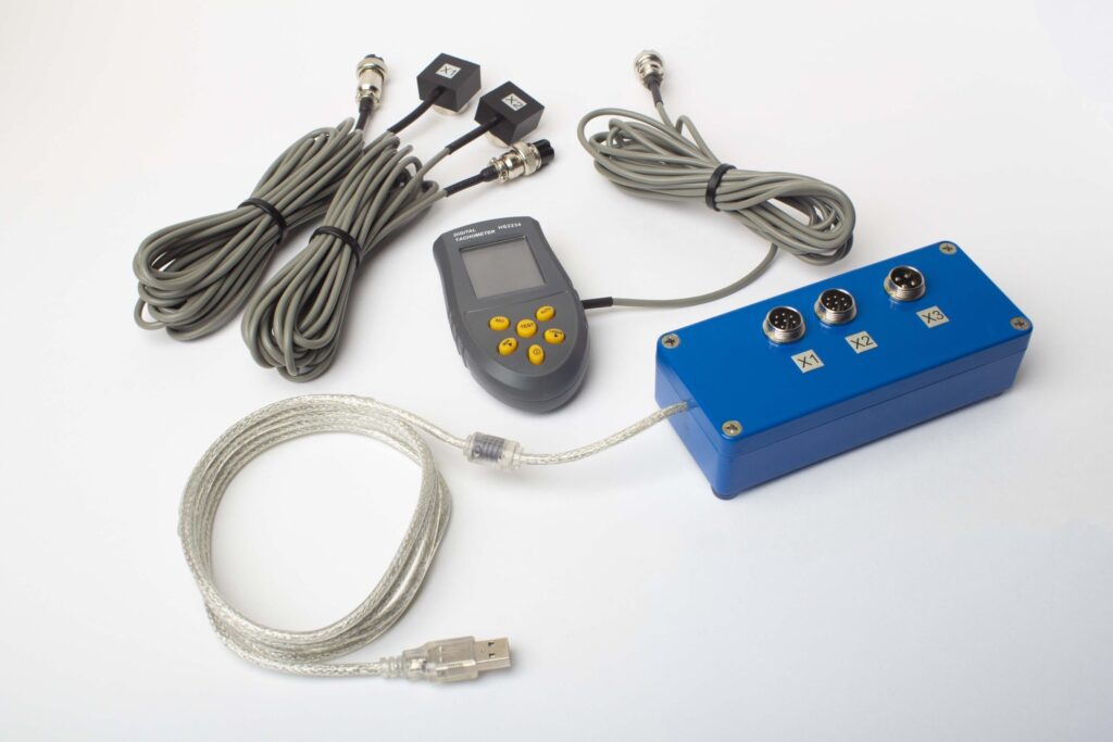
ಪೂರ್ಣ ಸಾಧನ ಪೆಟ್ಟಿಗೆಯಲ್ಲಿ ಏನಿದೆ
€1,975 · ಪೂರ್ಣ ಸಾಧನ ಪೆಟ್ಟಿಗೆ, ಸ್ಟಾಕ್ನಲ್ಲಿ, VAT ಇನ್ವಾಯ್ಸ್
- ಇಂಟರ್ಫೇಸ್ ಮಾಪನ ಘಟಕ (USB, 2 ಚಾನೆಲ್ಗಳು)
- ಎರಡು ವೈಬ್ರೇಶನ್ ಆಕ್ಸೆಲೆರೋಮೀಟರ್ಗಳು (4 ಮೀ ಕೇಬಲ್, 10 ಮೀ ಐಚ್ಛಿಕ)
- ಲೇಜರ್ ಟ್ಯಾಕೋಮೀಟರ್ / ಆಪ್ಟಿಕಲ್ ಹಂತ ಸಂವೇದಕ (50–500 ಮಿಮೀ)
- ಸಂವೇದಕದ ಮ್ಯಾಗ್ನೆಟಿಕ್ ಸ್ಟ್ಯಾಂಡ್
- ಪರೀಕ್ಷಾ ಮತ್ತು ತಿದ್ದುಪಡಿ ತೂಕಗಳಿಗೆ ಡಿಜಿಟಲ್ ಸ್ಕೇಲ್
- ವಿಂಡೋಸ್ ಬ್ಯಾಲೆನ್ಸಿಂಗ್ ಮತ್ತು ವಿಶ್ಲೇಷಣ ಸಾಫ್ಟ್ವೇರ್
- ಪ್ಲಾಸ್ಟಿಕ್ ಟ್ರಾನ್ಸ್ಪೋರ್ಟ್ ಕೇಸ್
ಸಂಪೂರ್ಣ ಕಿಟ್
ಯೂನಿಟ್ · 2 ಸೆನ್ಸರ್ಗಳು · ಲೇಜರ್ ಟ್ಯಾಕೋಮೀಟರ್ · ಮ್ಯಾಗ್ನೆಟಿಕ್ ಸ್ಟ್ಯಾಂಡ್ · ಡಿಜಿಟಲ್ ಸ್ಕೇಲ್ · ಸಾಫ್ಟ್ವೇರ್ · ಟ್ರಾನ್ಸ್ಪೋರ್ಟ್ ಕೇಸ್. ಬಾಕ್ಸ್ನಿಂದ ಬ್ಯಾಲೆನ್ಸಿಂಗ್ ಪ್ರಾರಂಭಿಸಲು ಅಗತ್ಯವಾದ ಎಲ್ಲವೂ ಸೇರಿದೆ.
OEM ಸೆಟ್
ಯೂನಿಟ್ · 2 ಸೆನ್ಸರ್ಗಳು · ಲೇಜರ್ ಟ್ಯಾಕೋಮೀಟರ್ · ಸಾಫ್ಟ್ವೇರ್. ಈಗಾಗಲೇ ಸ್ಟ್ಯಾಂಡ್, ಸ್ಕೇಲ್ ಮತ್ತು ಕೇಸ್ ಹೊಂದಿದ ಅಥವಾ ಯೂನಿಟ್ ಅನ್ನು ಬ್ಯಾಲೆನ್ಸಿಂಗ್ ಮೆಶಿನ್ಗೆ ಅಂತರ್ಗತಗೊಳಿಸುವ ಇಂಟಿಗ್ರೇಟರ್ಗಳಿಗೆ.
| ಪ್ಯಾರಾಮೀಟರ್ | ಮೌಲ್ಯ |
|---|---|
| ಮಾಪನ ಚ್ಯಾನೆಲ್ಗಳು | 2 (ಏಕ- & ದ್ವಿ-ತಲಾ ಬ್ಯಾಲೆನ್ಸಿಂಗ್) |
| ವೈಬ್ರೇಶನ್ ವೇಗ ಶ್ರೇಣಿ | 0.2–80 mm/s RMS |
| ಆವೃತ್ತಿ ವ್ಯಾಪ್ತಿ | 5–1000 Hz (≤10% amplitude error above 550 Hz) |
| ಮಾಪನ ನಿಖುರತೆ | ±5% ಪೂರ್ಣ ಸ್ಕೇಲ್ನ |
| ವಿಧಾನ | 3-ರನ್ ಪ್ರಭಾವ-ಗುಣಾಂಕ (1 ಅಥವಾ 2 ತಲಾಗಳು) |
| ವಿಶ್ಲೇಷಣೆ | 1× ನಲ್ಲಿ ವೈಶಾಲ್ಯ & ಹಂತ, FFT ಸ್ಪೆಕ್ಟ್ರಮ್ & ತರಂಗರೂಪ, ಉಳಿಸಿದ ವರದಿಗಳು |
| ಲ್ಯಾಪ್ಟಾಪ್ | ಸೇರಿಲ್ಲ (ವಿಂಡೋಸ್ PC, ವಿನಂತಿಯ ಮೇರೆಗೆ ಲಭ್ಯವಿದೆ) |
ಫೀಲ್ಡ್ ಬ್ಯಾಲೆನ್ಸಿಂಗ್ ವಿರುದ್ಧ ಬ್ಯಾಲೆನ್ಸಿಂಗ್ ಯಂತ್ರ — ನಿಮ್ಮ ಎಕ್ಸ್ಹಾಸ್ಟರ್ಗೆ ಯಾವುದು ಸರಿಯಾಗಿದೆ?
| ಘಟಕ | ಕ್ಷೇತ್ರ ಸಮತೋಲನ (Balanset-1A) | ಸಮತೋಲನ ಯಂತ್ರ (ಕಾರ್ಯಾಲಯ) |
|---|---|---|
| ಇಂಪೆಲ್ಲರ್ನ್ನು ಹೌಸಿಂಗ್ನಿಂದ ತೆಗೆದುಹಾಕಲಾಗುತ್ತದೆಯೇ? | ಇಲ್ಲ — ಸ್ಥಳದಲ್ಲಿ ಚಲಿಸುತ್ತದೆ | ಹೌದು — ಸಂಪೂರ್ಣ ವಿಘಟನ ಅಗತ್ಯ |
| ಡಕ್ಟ್ವರ್ಕ್ ಬೇರ್ಪಡಿಸಬೇಕೇ? | ಇಲ್ಲ | ಹೌದು |
| ಉತ್ಪಾದನ ನಿಶ್ಚಲತೆ | ಸಂವೇದಕ ಅಳವಡಿಕೆ ಮಾತ್ರ (<15 ನಿಮಿಷ) | ಗಂಟೆಗಳಿಂದ ದಿನಗಳವರೆಗೆ (ಬೇರ್ಪಡಿಕೆ, ಸಾಗಾಟ, ಬ್ಯಾಲೆನ್ಸ್, ಮರುಸ್ಥಾಪನೆ) |
| ಸಮತೋಲನ ವೇಗ | ನಿಜವಾದ ಕಾರ್ಯಾಚರಣಾ ವೇಗ & ಪ್ರೊಸೆಸ್ ಪರಿಸ್ಥಿತಿಗಳು | ಪ್ರತ್ಯೇಕ ಕಡಿಮೆ-ವೇಗ ಸ್ಪಿಂಡಲ್ |
| ಥರ್ಮಲ್ ವಿಕೃತಿ & ಜಮಾವಣೆಗಳನ್ನು ಪರಿಗಣಿಸುತ್ತದೆ | ಹೌದು — ಸಂಪೂರ್ಣ ಅಸೆಂಬ್ಲಿಯನ್ನು ಓಡುತ್ತಿರುವ ಸ್ಥಿತಿಯಲ್ಲೇ ಬ್ಯಾಲೆನ್ಸ್ ಮಾಡಲಾಗಿದೆ | ಇಲ್ಲ — ಸ್ವಚ್ಛಗೊಳಿಸಿದ, ತಣ್ಣನೆಯ ಇಂಪೆಲ್ಲರ್ ಮಾತ್ರ |
| ಅರಿಕೆ-ಚಾಲಿತ ಮರು-ಅಸಮತೋಲನವನ್ನು ನಿರ್ವಹಿಸುತ್ತದೆ | ಹೌದು — ಸ್ಥಳದಲ್ಲೇ ಮರುಕಳಿಸಬಹುದು, ಬೇರ್ಪಡಿಕೆ ಬೇಡ | ಪ್ರತಿ ಬಾರಿ ಸಂಪೂರ್ಣವಾಗಿ ತೆಗೆದುಹಾಕಬೇಕು |
| ಮಾನದಂಡಗಳು ಪೂರೈಸಲಾಗಿದೆ | ISO 14694, ISO 21940-11 | ISO 21940-11 |
| ಉಪಕರಣ ವೆಚ್ಚ | €1,975 (ಪೂರ್ಣ ಕಿಟ್) | €10,000 – €50,000+ |
| ವಿಶಿಷ್ಟ ಕೆಲಸ ಸಮಯ | <ಸ್ಥಳದಲ್ಲಿ 1 ಘಂಟೆ | ಒಟ್ಟು 1–3 ದಿನಗಳು |
ಫ್ಯಾನ್ ಓಡಬಹುದಾದಾಗ ಮತ್ತು ರೋಟರ್ rigidity ಮಾನದಂಡ ಪೂರೈಸಿದಾಗ ಎಕ್ಸ್ಹಾಸ್ಟರ್ಗಳಿಗೆ ಫೀಲ್ಡ್ ಬ್ಯಾಲೆನ್ಸಿಂಗ್ ಪ್ರಾಥಮಿಕ ಆಯ್ಕೆ — ಮೊದಲ ಕ್ರಿಟಿಕಲ್ ವೇಗಕ್ಕಿಂತ ಕಡಿಮೆ ಕಾರ್ಯನಿರ್ವಹಿಸುವ ಬಹುಪಾಲು ಕೈಗಾರಿಕಾ ಇಂಪೆಲ್ಲರ್ಗಳಿಗೆ ಇದು ಅನ್ವಯಿಸುತ್ತದೆ. ಯಾವುದೇ ರನ್ ಸಮಯವಿಲ್ಲದ ಹೊಸ ಇಂಪೆಲ್ಲರ್ಗಳಿಗೆ, ಅಥವಾ ಬೇರೆ ಕಾರಣಗಳಿಂದ overhaul ಮಾಡಲಾಗುತ್ತಿರುವ ಬಹಳ ದೊಡ್ಡ ರೋಟರ್ಗಳಿಗೆ ವರ್ಕ್ಶಾಪ್ ಯಂತ್ರ ಇನ್ನೂ ಸೂಕ್ತವಾಗಿದೆ.
ನೈಜ ಎಕ್ಸ್ಹಾಸ್ಟರ್ ಬ್ಯಾಲೆನ್ಸಿಂಗ್ ಉದಾಹರಣೆಗಳು
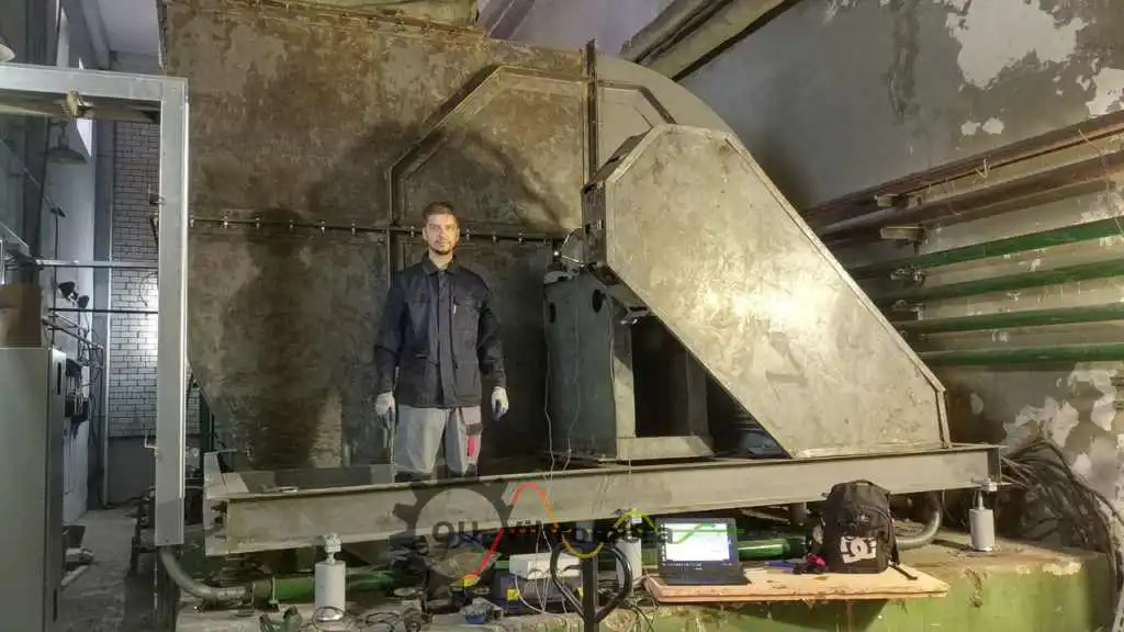
ಕೈಗಾರಿಕಾ ಎಕ್ಸ್ಹಾಸ್ಟರ್ಗಳು
ಕಾರ್ಯಾಚರಣಾ ಪರಿಸ್ಥಿತಿಗಳಲ್ಲೇ ಕೈಗಾರಿಕಾ ಎಕ್ಸ್ಹಾಸ್ಟರ್ ಫ್ಯಾನ್ಗಳ ಇನ್-ಸಿಟು ಬ್ಯಾಲೆನ್ಸಿಂಗ್, ಬ್ಯಾಲೆನ್ಸಿಂಗ್ಗೂ ಮೊದಲು ಮತ್ತು ನಂತರದ ಕಂಪನ ಡೇಟಾವೊಂದಿಗೆ.
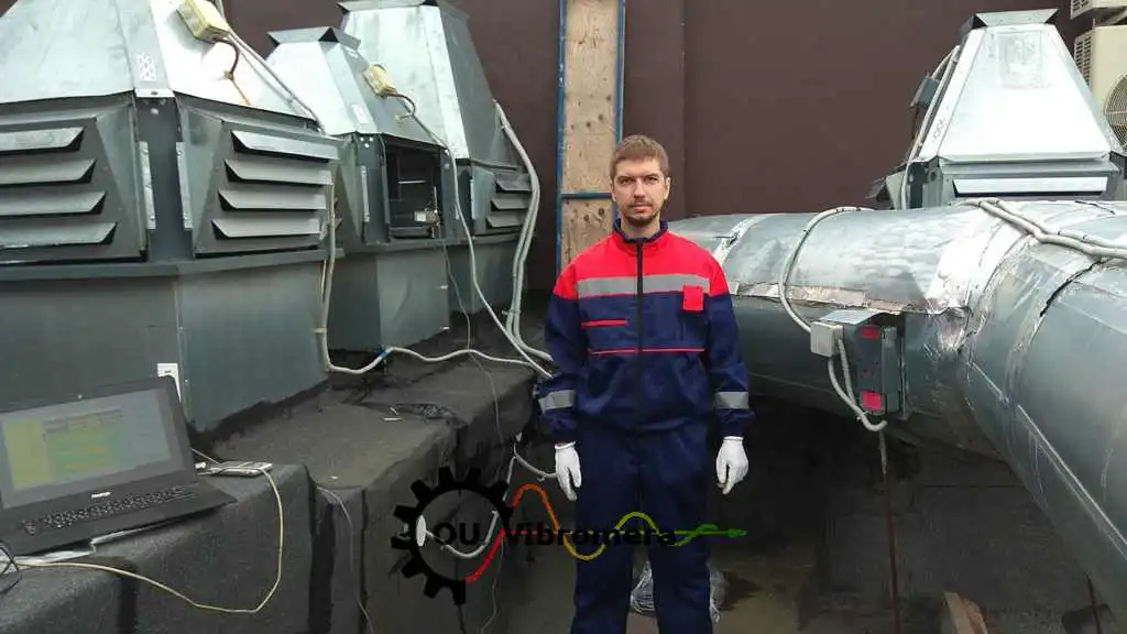
ಸೈಟ್ನಲ್ಲಿರುವ ಎಕ್ಸಾಸ್ಟ್ ಫ್ಯಾನ್
Balanset-1A ಬಳಸಿ ಸಂಪೂರ್ಣ ಕಂಪನ ಮಾಪನ ಮತ್ತು ಫೇಸ್ ವಿಶ್ಲೇಷಣೆಯೊಂದಿಗೆ ಎಕ್ಸ್ಹಾಸ್ಟ್ ಫ್ಯಾನ್ನ ಆನ್-ಸೈಟ್ ಬ್ಯಾಲೆನ್ಸಿಂಗ್.

HVAC ಎಕ್ಸ್ಹಾಸ್ಟ್ ಫ್ಯಾನ್ ಇಂಪೆಲ್ಲರ್
HVAC ಮತ್ತು ವಾತಾಯನ ಎಕ್ಸ್ಹಾಸ್ಟ್ ಫ್ಯಾನ್ ಇಂಪೆಲ್ಲರ್ನ ಹಂತ-ಹಂತದ ಫೀಲ್ಡ್ ಬ್ಯಾಲೆನ್ಸಿಂಗ್, ಸೆನ್ಸರ್ ಅಳವಡಿಕೆಯಿಂದ ಅಂತಿಮ ಪರಿಶೀಲನೆವರೆಗೆ ದಾಖಲಿಸಲಾಗಿದೆ.
ಉಚಿತ ಎಕ್ಸ್ಹಾಸ್ಟರ್ & ಫ್ಯಾನ್ ಕ್ಯಾಲ್ಕುಲೇಟರ್ಗಳು
ಎಕ್ಸ್ಹಾಸ್ಟರ್ ಬ್ಯಾಲೆನ್ಸಿಂಗ್ FAQ
ಬಿಸಿ, ಧೂಳು ಅಥವಾ ಕರೋಸಿವ್ ಅನಿಲವನ್ನು ಹಸ್ತಾಂತರಿಸುತ್ತಿರುವಾಗಲೇ ಎಕ್ಸ್ಹಾಸ್ಟರ್ಗಳನ್ನು ಬ್ಯಾಲೆನ್ಸ್ ಮಾಡಬಹುದೇ?
ನಮ್ಮ ಎಕ್ಸ್ಹಾಸ್ಟರ್ನಲ್ಲಿ ಸ್ಕೇಲ್ ಜಮಾವಣೆಗಳು ಬೇಗ ರೋಟರ್ನ್ನು ಮರು-ಅಸಮತೋಲನಗೊಳಿಸುತ್ತವೆ — ಇದನ್ನು ನಾವು ಹೇಗೆ ನಿರ್ವಹಿಸಬೇಕು?
ಒಂದು ತಿದ್ದುಪಡಿ ಸಮತಲ ಸಾಕೇ, ಅಥವಾ ಎರಡು ಬೇಕೇ?
ಬ್ಯಾಲೆನ್ಸಿಂಗ್ ನಂತರ ಕೂಡ ಕಂಪನ ಬೇಗ ಹಿಂದಿರುಗಿದರೆ ಏನು?
Balanset-1A ದೊಡ್ಡ, ಭಾರವಾದ ಎಕ್ಸ್ಹಾಸ್ಟರ್ ಫ್ಯಾನ್ಗಳ ಮೇಲೂ ಕೆಲಸ ಮಾಡುತ್ತದೆಯೇ?
ಎಕ್ಸ್ಹಾಸ್ಟರ್ ಫ್ಯಾನ್ಗಳು ಯಾವ ಬ್ಯಾಲೆನ್ಸ್ ಗ್ರೇಡ್ನ್ನು ಪೂರೈಸಬೇಕು?
ಸಿದ್ಧಾಂತ ಕಲಿಯಿರಿ
ಎಕ್ಸ್ಹಾಸ್ಟರ್ ಬೇಯರಿಂಗ್ಗಳನ್ನು ಮರುಮರು ಬದಲಿಸಬೇಡಿ — ರೋಟರ್ನ್ನು ಅದೇ ಸ್ಥಳದಲ್ಲೇ ಬ್ಯಾಲೆನ್ಸ್ ಮಾಡಿ
Balanset-1A ಎಕ್ಸ್ಹಾಸ್ಟರ್ಗಳು, ಧೂಳು ಎಕ್ಸ್ಟ್ರಾಕ್ಟರ್ಗಳು ಮತ್ತು ಇಂಡ್ಯೂಸ್ಡ್-ಡ್ರಾಫ್ಟ್ ಫ್ಯಾನ್ಗಳಿಗೆ ಕಾರ್ಯಾಚರಣಾ ವೇಗದಲ್ಲೇ, ನಿಜವಾದ ಪ್ರೊಸೆಸ್ ಪರಿಸ್ಥಿತಿಗಳಲ್ಲೇ single- ಮತ್ತು two-plane in-situ ಬ್ಯಾಲೆನ್ಸಿಂಗ್ ಮಾಡುತ್ತದೆ. ಇಂಪೆಲ್ಲರ್ ತೆಗೆದುಹಾಕುವುದು ಬೇಡ, ಡಕ್ಟ್ ಬೇರ್ಪಡಿಸುವುದು ಬೇಡ — ISO 14694 ಮತ್ತು ISO 21940-11 ಗೆ ದಾಖಲಿತ ಉಳಿದ-ಅಸಮತೋಲನ ಅಂಕಿಗಳೊಂದಿಗೆ ಇನ್ನಷ್ಟು ಮೌನವಾಗಿ, ಹೆಚ್ಚು ಕಾಲ ಇರುವ ಫ್ಯಾನ್ ಮಾತ್ರ.
