ਬੈਲੇਂਸਿੰਗ ਸੇਵਾਵਾਂ › ਪੱਖੇ › ਐਗਜ਼ੌਸਟਰ & ਡਰਾਫਟ ਫੈਨ
ਐਗਜ਼ੌਸਟਰ & ਇੰਡਿਊਸਡ-ਡਰਾਫਟ ਫੈਨ ਬੈਲੇਂਸਿੰਗ — ਇਨ-ਸੀਟੂ, ਓਪਰੇਟਿੰਗ ਸਪੀਡ ‘ਤੇ
ਐਗਜ਼ੌਸਟਰ, ਡਸਟ ਐਕਸਟਰੈਕਟਰ ਅਤੇ ਇੰਡਿਊਸਡ-ਡਰਾਫਟ ਫੈਨ ਸਭ ਤੋਂ ਕਠਿਨ ਪ੍ਰੋਸੈੱਸ ਵਾਤਾਵਰਣਾਂ ਵਿੱਚ ਕੰਮ ਕਰਦੇ ਹਨ — ਅਪਘਰਸ਼ਕ, ਗਰਮ ਜਾਂ ਖੋਰਕਾਰੀ ਗੈਸ ਧਾਰਾਵਾਂ ਨੂੰ ਸੰਭਾਲਦੇ ਹੋਏ ਜੋ ਲਗਾਤਾਰ ਬਲੇਡਾਂ ਨੂੰ ਘਸਾਉਂਦੀਆਂ ਹਨ ਅਤੇ ਅਸਮਿੱਟ ਜਮਾਵਾਂ ਬਣਾਉਂਦੀਆਂ ਹਨ। ਅਸੀਂ ਸੁਚਾਰੂ ਚਾਲ ਬਹਾਲ ਕਰਦੇ ਹਾਂ ਸਥਾਨ 'ਤੇ ਹੀ, ਓਪਰੇਟਿੰਗ ਸਪੀਡ 'ਤੇ, ਇੰਪੈਲਰ ਨੂੰ ਉਤਾਰੇ ਬਿਨਾਂ ਜਾਂ ਡਕਟਵਰਕ ਨੂੰ ਡਿਸਕਨੈਕਟ ਕੀਤੇ ਬਿਨਾਂ — ਬੇਅਰਿੰਗ ਫੇਲਿਊਰ ਅਤੇ ਸਟ੍ਰਕਚਰਲ ਫਟੀਗ ਦੇ ਮੁੱਖ ਕਾਰਨ ਨੂੰ ਇੱਕੋ ਆਨ-ਸਾਈਟ ਸੈਸ਼ਨ ਵਿੱਚ ਖ਼ਤਮ ਕਰਦੇ ਹੋਏ।
ਸੰਖੇਪ ਵਿੱਚ: ਐਗਜ਼ੌਸਟਰ ਅਤੇ ਇੰਡਿਊਸਡ-ਡਰਾਫਟ ਫੈਨ ਬੈਲੇਂਸਿੰਗ ਇਨ-ਸੀਟੂ, ਸਧਾਰਨ ਓਪਰੇਟਿੰਗ ਸਪੀਡ ‘ਤੇ, ਇਨਫਲੂਐਂਸ-ਕੋਐਫੀਸ਼ੀਐਂਟ ਵਿਧੀ ਦੀ ਵਰਤੋਂ ਕਰਕੇ ਕੀਤੀ ਜਾਂਦੀ ਹੈ। ਬੇਅਰਿੰਗ ਹਾਊਸਿੰਗ ‘ਤੇ ਲੱਗਿਆ ਇੱਕ ਵਾਈਬ੍ਰੇਸ਼ਨ ਐਕਸਲਰੋਮੀਟਰ ਅਤੇ ਸ਼ਾਫਟ ‘ਤੇ ਲੇਜ਼ਰ ਟੈਕੋਮੀਟਰ ਮੌਜੂਦਾ ਅਨਬੈਲੇਂਸ ਸਥਿਤੀ ਨੂੰ ਮਾਪਦੇ ਹਨ; Balanset-1A ਸਟੀਕ ਸੁਧਾਰ ਪੁੰਜ ਅਤੇ ਕੋਣ ਦੀ ਗਣਨਾ ਕਰਦਾ ਹੈ। ਨਾ ਇੰਪੈਲਰ ਹਟਾਉਣ ਦੀ ਲੋੜ, ਨਾ ਡਕਟ ਡਿਸਕਨੈਕਸ਼ਨ ਦੀ — ਇੱਕ ਖਾਸ ਸਿੰਗਲ-ਪਲੇਨ ਕੰਮ ਇੱਕ ਘੰਟੇ ਤੋਂ ਘੱਟ ਸਮੇਂ ਵਿੱਚ ਪੂਰਾ ਹੋ ਜਾਂਦਾ ਹੈ, ਵਾਈਬ੍ਰੇਸ਼ਨ ਨੂੰ 70 % ਜਾਂ ਵੱਧ ਘਟਾਉਂਦਾ ਹੈ ਅਤੇ ਬੇਅਰਿੰਗ ਸਰਵਿਸ ਲਾਈਫ ਨੂੰ ਅੱਠ ਤੋਂ ਦਸ ਗੁਣਾ ਵਧਾਉਂਦਾ ਹੈ। ਖੋਰ ਅਤੇ ਜਮਾਵ-ਪ੍ਰੇਰਿਤ ਮੁੜ-ਅਨਬੈਲੇਂਸ ਨੂੰ ਬਿਨਾਂ ਕਿਸੇ ਵਰਕਸ਼ਾਪ ਸ਼ਮੂਲੀਅਤ ਦੇ ਉਸੇ ਵਿਜ਼ਿਟ ਅੰਤਰਾਲ ‘ਤੇ ਵਾਰ-ਵਾਰ ਠੀਕ ਕੀਤਾ ਜਾ ਸਕਦਾ ਹੈ।
ਸੰਕੇਤ ਕਿ ਤੁਹਾਡਾ ਐਗਜ਼ੌਸਟਰ ਜਾਂ ਡਰਾਫਟ ਫੈਨ ਅਸੰਤੁਲਿਤ ਹੈ
ਸੰਤੁਲਨ ਗੁਆ ਚੁੱਕੇ ਐਗਜ਼ੌਸਟਰ ਅਤੇ ID ਫੈਨ ਮਸ਼ੀਨ ਸਿਹਤ ਦੇ ਵਿਗੜਦੇ ਹੋਏ ਇੱਕ ਪਛਾਣਯੋਗ ਪੈਟਰਨ ਦਿਖਾਉਂਦੇ ਹਨ। ਇਹਨਾਂ ਵਿੱਚੋਂ ਕੋਈ ਵੀ ਲੱਛਣ ਵਾਈਬ੍ਰੇਸ਼ਨ ਮਾਪ ਨੂੰ ਜਾਇਜ਼ ਠਹਿਰਾਉਂਦਾ ਹੈ ਅਤੇ, ਜੇ 1× RPM ਕੰਪੋਨੈਂਟ ਹਾਵੀ ਹੋਵੇ, ਤਾਂ ਇੱਕ ਇਨ-ਸੀਟੂ ਬੈਲੇਂਸਿੰਗ ਸੈਸ਼ਨ:
ਐਗਜ਼ੌਸਟਰ & ਡਰਾਫਟ ਫੈਨ ਸੰਤੁਲਨ ਕਿਉਂ ਗੁਆਉਂਦੇ ਹਨ — ਅਤੇ ਇਸ ਦੀ ਕੀਮਤ ਕੀ ਹੈ
ਐਗਜ਼ੌਸਟਰ ਅਤੇ ਇੰਡਿਊਸਡ-ਡਰਾਫਟ ਫੈਨ ਜਾਣਬੁੱਝ ਕੇ ਉਸ ਥਾਂ ਲਗਾਏ ਜਾਂਦੇ ਹਨ ਜਿੱਥੋਂ ਪ੍ਰੋਸੈੱਸ ਸਟ੍ਰੀਮ ਦਾ ਗੰਦਾ, ਅਪਘਰਸ਼ਕ ਜਾਂ ਰਸਾਇਣਕ ਤੌਰ ‘ਤੇ ਹਮਲਾਵਰ ਹਿੱਸਾ ਲੰਘਣਾ ਲਾਜ਼ਮੀ ਹੁੰਦਾ ਹੈ — ਜਿਸ ਦਾ ਮਤਲਬ ਹੈ ਕਿ ਉਹਨਾਂ ਦੇ ਇੰਪੈਲਰ ਲਗਾਤਾਰ ਹਮਲੇ ਹੇਠ ਰਹਿੰਦੇ ਹਨ। ਫਲਾਈ-ਐਸ਼, ਕਲਿੰਕਰ ਧੂੜ ਅਤੇ ਖਣਿਜ ਕਣ ਬਲੇਡਾਂ ਨੂੰ ਅਸਮਿੱਟ ਢੰਗ ਨਾਲ ਘਸਾਉਂਦੇ ਹਨ, ਇੱਕ ਸੈਕਟਰ ਤੋਂ ਦੂਜੇ ਨਾਲੋਂ ਵੱਧ ਸਮੱਗਰੀ ਹਟਾਉਂਦੇ ਹੋਏ। ਸਕੇਲ, ਟਾਰ ਅਤੇ ਚਿਪਚਿਪੇ ਕਣ ਬਲੇਡ ਫੇਸਾਂ ਅਤੇ ਇੰਪੈਲਰ ਡਿਸਕ ‘ਤੇ ਅਣਅਨੁਮਾਨਿਤ ਧੱਬਿਆਂ ਵਿੱਚ ਜਮ੍ਹਾਂ ਹੁੰਦੇ ਹਨ। ਮੇਨਟੇਨੈਂਸ ਦੌਰਾਨ ਲਗਾਏ ਗਏ ਸੁਰੱਖਿਆਤਮਕ ਵੀਅਰ ਲਾਈਨਰ ਜਾਂ ਵੈਲਡ-ਡਿਪਾਜ਼ਿਟਿਡ ਹਾਰਡ-ਫੇਸਿੰਗ ਸਥਾਨਕ ਪੁੰਜ ਜੋੜਦੇ ਹਨ। ਖੋਰ (ਕੋਰੋਜ਼ਨ) ਦੂਜਿਆਂ ਦੇ ਮੁਕਾਬਲੇ ਕੁਝ ਖਾਸ ਬਲੇਡਾਂ ਜਾਂ ਸੈਗਮੈਂਟਾਂ ‘ਤੇ ਤੇਜ਼ੀ ਨਾਲ ਹਮਲਾ ਕਰਦਾ ਹੈ। ਸ਼ੁਰੂਆਤ ਅਤੇ ਬੰਦ ਹੋਣ ਦੇ ਚੱਕਰਾਂ ਦੌਰਾਨ ਥਰਮਲ ਵਿਗਾੜ ਪੁੰਜ ਦੇ ਕੇਂਦਰ ਨੂੰ ਬਦਲ ਸਕਦਾ ਹੈ ਜਿਵੇਂ ਰੋਟਰ ਫੈਲਦਾ ਅਤੇ ਸੁੰਗੜਦਾ ਹੈ।
ਇਹਨਾਂ ਵਿੱਚੋਂ ਹਰੇਕ ਮਕੈਨਿਜ਼ਮ ਪੁੰਜ ਦੇ ਕੇਂਦਰ ਨੂੰ ਜਿਓਮੈਟ੍ਰਿਕ ਰੋਟੇਸ਼ਨ ਧੁਰੇ ਤੋਂ ਦੂਰ ਲੈ ਜਾਂਦਾ ਹੈ। ਕਿਉਂਕਿ ਸੈਂਟਰੀਫਿਊਗਲ ਫੋਰਸ ਵਰਗ ਘੁੰਮਣ ਦੀ ਸਪੀਡ ਦੇ ਨਾਲ ਵਧਦੀ ਹੈ, ਬਲੇਡ ਟਿਪ ‘ਤੇ 50 g ਦਾ ਇੱਕ ਮਾਮੂਲੀ ਪੁੰਜ ਆਫਸੈੱਟ ਵੀ 750–1,500 rpm ਦੀ ਉਦਯੋਗਿਕ ਫੈਨ ਸਪੀਡ ‘ਤੇ ਕਈ ਕਿਲੋਨੈਅਟਨ ਡਾਇਨਾਮਿਕ ਰੇਡੀਅਲ ਲੋਡ ਪੈਦਾ ਕਰਦਾ ਹੈ — ਅਤੇ ਵੱਧ ਸਪੀਡ ‘ਤੇ ਹੋਰ ਵੀ ਜ਼ਿਆਦਾ।
ਪਲਾਂਟ ਇੰਜੀਨੀਅਰ ਵਿੱਤੀ ਨੁਕਸਾਨ ਨੂੰ ਚੰਗੀ ਤਰ੍ਹਾਂ ਸਮਝਦੇ ਹਨ: ਐਮਰਜੈਂਸੀ ਬੇਅਰਿੰਗ ਬਦਲਣ ਲਈ ਗੈਰ-ਯੋਜਨਾਬੱਧ ਬੰਦ, ਵੱਡੇ ਗਰਮ-ਗੈਸ ਫੈਨਾਂ ਤੱਕ ਪਹੁੰਚਣ ਲਈ ਲੇਬਰ ਅਤੇ ਕ੍ਰੇਨ ਸਮਾਂ, ਘਟੀ ਹੋਈ ਡਰਾਟ ਸਮਰੱਥਾ, ਵਧੀ ਹੋਈ ਵਿਸ਼ੇਸ਼ ਊਰਜਾ ਖਪਤ, ਅਤੇ ਇੰਪੈਲਰ ਡਿਸਕ ਜਾਂ ਸ਼ਾਫਟ ਨੂੰ ਆਖ਼ਰਕਾਰ ਸਟ੍ਰਕਚਰਲ ਨੁਕਸਾਨ। ਸਮੇਂ-ਸਮੇਂ ‘ਤੇ ਇਨ-ਸੀਟੂ ਬੈਲੇਂਸਿੰਗ — ਆਮ ਤੌਰ ‘ਤੇ ਇੱਕ ਘੰਟੇ ਤੋਂ ਘੱਟ ਸਮੇਂ ਵਿੱਚ ਪੂਰੀ ਹੁੰਦੀ ਹੈ — ਸਰੋਤ ‘ਤੇ ਡਾਇਨਾਮਿਕ ਲੋਡ ਨੂੰ ਘਟਾਉਂਦੀ ਹੈ ਅਤੇ ਇਨਵੇਸਿਵ ਮੇਨਟੇਨੈਂਸ ਦਖਲਅੰਦਾਜ਼ੀਆਂ ਵਿਚਕਾਰ ਅੰਤਰਾਲ ਨੂੰ ਬਹੁਤ ਵਧਾਉਂਦੀ ਹੈ।
ਵਾਈਬ੍ਰੇਸ਼ਨ ਅੱਧੀ ਕਰਨ ਨਾਲ ਬੇਅਰਿੰਗ ਦੀ ਉਮਰ ਕਈ ਗੁਣਾ ਕਿਉਂ ਵਧਦੀ ਹੈ
ਅਸੀਂ ਐਗਜ਼ੌਸਟਰ ਨੂੰ ਕਿਵੇਂ ਸੰਤੁਲਿਤ ਕਰਦੇ ਹਾਂ — ਕਦਮ ਦਰ ਕਦਮ
Balanset-1A ਨਾਲ ਫੀਲਡ ਬੈਲੇਂਸਿੰਗ ਇਨਫਲੂਐਂਸ-ਕੋਐਫੀਸ਼ੀਐਂਟ ਵਿਧੀ ਦੀ ਪਾਲਣਾ ਕਰਦੀ ਹੈ — ਉਹੀ ਸਿਸਟਮੈਟਿਕ ਪ੍ਰਕਿਰਿਆ ਜੋ ਰੋਟਰ ਦੀ ਜਿਓਮੈਟਰੀ, ਪ੍ਰੋਸੈੱਸ ਤਾਪਮਾਨ ਜਾਂ ਧੂੜ ਲੋਡਿੰਗ ਦੀ ਪਰਵਾਹ ਕੀਤੇ ਬਿਨਾਂ ਕੰਮ ਕਰਦੀ ਹੈ:
- ਸੈਂਸਰ ਲਗਾਓ। ਇੱਕ ਵਾਈਬ੍ਰੇਸ਼ਨ ਐਕਸਲਰੋਮੀਟਰ ਬੇਅਰਿੰਗ ਹਾਊਸਿੰਗ ‘ਤੇ ਮੈਗਨੈਟਿਕ ਤੌਰ ‘ਤੇ ਫਿਕਸ ਕੀਤਾ ਜਾਂਦਾ ਹੈ ਅਤੇ ਇੱਕ ਲੇਜ਼ਰ ਟੈਕੋਮੀਟਰ ਸ਼ਾਫਟ ਜਾਂ ਇੰਪੈਲਰ ਹੱਬ ‘ਤੇ ਲੱਗੀ ਇੱਕ ਰਿਫਲੈਕਟਿਵ ਸਟ੍ਰਿਪ ‘ਤੇ ਨਿਸ਼ਾਨਾ ਲਗਾਇਆ ਜਾਂਦਾ ਹੈ। ਕੋਈ ਵੀ ਡਿਸਅਸੈਂਬਲੀ ਦੀ ਲੋੜ ਨਹੀਂ — ਫੈਨ ਪੂਰੇ ਸਮੇਂ ਸਧਾਰਨ ਪ੍ਰੋਸੈੱਸ ਹਾਲਤਾਂ ਹੇਠ ਚੱਲਦਾ ਰਹਿੰਦਾ ਹੈ। ਸਿੰਗਲ-ਪਲੇਨ ਲਈ ਇੱਕ ਬੇਅਰਿੰਗ ਤੱਕ ਪਹੁੰਚ ਕਾਫ਼ੀ ਹੈ; ਦੋ-ਪਲੇਨ ਸੁਧਾਰ ਲਈ ਦੋਵੇਂ ਸਿਰੇ ਦੀਆਂ ਬੇਅਰਿੰਗਾਂ ਤੱਕ ਪਹੁੰਚ ਦੀ ਲੋੜ ਹੈ।
- ਬੇਸਲਾਈਨ ਮਾਪ ਲਓ। ਪੂਰੀ ਓਪਰੇਟਿੰਗ ਸਪੀਡ 'ਤੇ ਇੱਕ ਰਨ ਵਾਈਬ੍ਰੇਸ਼ਨ ਐਂਪਲੀਟਿਊਡ ਅਤੇ 1× RPM 'ਤੇ ਫੇਜ਼ ਐਂਗਲ ਰਿਕਾਰਡ ਕਰਦਾ ਹੈ, ਜੋ ਮੌਜੂਦਾ ਅਨਬੈਲੰਸ ਸਥਿਤੀ ਨੂੰ ਮੈਗਨੀਟਿਊਡ ਅਤੇ ਦਿਸ਼ਾ ਵਿੱਚ ਸਥਾਪਿਤ ਕਰਦਾ ਹੈ।
- ਟ੍ਰਾਇਲ ਵੇਟ ਲਗਾਓ। ਇੱਕ ਜਾਣਿਆ-ਪਛਾਣਿਆ ਟੈਸਟ ਮਾਸ ਇੰਪੈਲਰ ਡਿਸਕ ਜਾਂ ਹੱਬ ਫਲੈਂਜ ‘ਤੇ ਇੱਕ ਦਰਜ ਕੋਣੀ ਪੁਜ਼ੀਸ਼ਨ ‘ਤੇ ਬੋਲਟ ਜਾਂ ਕਲੈਂਪ ਕੀਤਾ ਜਾਂਦਾ ਹੈ। ਇੱਕ ਦੂਜੀ ਰਨ ਬਦਲੀ ਹੋਈ ਵਾਈਬ੍ਰੇਸ਼ਨ ਪ੍ਰਤੀਕਿਰਿਆ ਨੂੰ ਕੈਪਚਰ ਕਰਦੀ ਹੈ — ਇਹ ਸੁਧਾਰ ਗਣਨਾ ਲਈ ਡਿਵਾਈਸ ਨੂੰ ਇਸ ਦਾ ਇਨਫਲੂਐਂਸ ਕੋਐਫੀਸ਼ੀਐਂਟ ਦਿੰਦੀ ਹੈ।
- ਉਪਕਰਨ ਨੂੰ ਗਣਨਾ ਕਰਨ ਦਿਓ। Balanset-1A ਸਟੀਕ ਸੁਧਾਰ ਪੁੰਜ ਅਤੇ ਕੋਣੀ ਪਲੇਸਮੈਂਟ ਦਿਖਾਉਣ ਲਈ ਇਨਫਲੂਐਂਸ-ਕੋਐਫੀਸ਼ੀਐਂਟ ਐਲਗੋਰਿਦਮ ਲਾਗੂ ਕਰਦਾ ਹੈ — ਕੰਪੈਕਟ ਡਿਸਕ ਇੰਪੈਲਰਾਂ ਲਈ ਇੱਕ ਪਲੇਨ, ਚੌੜੇ ਜਾਂ ਡੂੰਘੇ ਇੰਪੈਲਰਾਂ ਲਈ ਦੋ ਪਲੇਨ ਜਿੱਥੇ ਅਨਬੈਲੇਂਸ ਰੋਟਰ ਦੀ ਲੰਬਾਈ ਦੇ ਨਾਲ ਵੰਡਿਆ ਹੁੰਦਾ ਹੈ।
- ਸੁਧਾਰ ਵਜ਼ਨ ਫਿੱਟ ਕਰੋ। ਗਣਨਾ ਕੀਤਾ ਗਿਆ ਪੁੰਜ ਇੰਪੈਲਰ ਡਿਸਕ, ਹੱਬ ਫਲੈਂਜ ਜਾਂ ਬਲੇਡ ਰੂਟ ‘ਤੇ ਨਿਰਧਾਰਿਤ ਕੋਣ ‘ਤੇ ਵੈਲਡ, ਬੋਲਟ ਜਾਂ ਕਲੈਂਪ ਕੀਤਾ ਜਾਂਦਾ ਹੈ। ਜਿਵੇਂ-ਜਿਵੇਂ ਜਮਾਵ ਮੁੜ-ਜਮ੍ਹਾਂ ਹੁੰਦੇ ਹਨ, ਦੁਹਰਾਈ ਬੈਲੇਂਸਿੰਗ ਨੂੰ ਤੇਜ਼ ਬਣਾਉਣ ਲਈ ਸਥਾਈ ਸਟੱਡ ਪੁਜ਼ੀਸ਼ਨਾਂ ਪਹਿਲਾਂ ਤੋਂ ਲਗਾਈਆਂ ਜਾ ਸਕਦੀਆਂ ਹਨ।
- ਤਸਦੀਕ ਕਰੋ ਅਤੇ ਦਸਤਾਵੇਜ਼ੀਕਰਨ ਕਰੋ। ਇੱਕ ਅੰਤਿਮ ਮਾਪ ਰਨ ਪੁਸ਼ਟੀ ਕਰਦੀ ਹੈ ਕਿ ਰਹਿੰਦ-ਖੂੰਹਦ ਅਨਬੈਲੇਂਸ ਫੈਨ ਦੇ ਬੈਲੇਂਸ ਗ੍ਰੇਡ ਲਈ ISO ਸਹਿਣਸ਼ੀਲਤਾ ਬੈਂਡ ਦੇ ਅੰਦਰ ਹੈ। Balanset-1A ਮੇਨਟੇਨੈਂਸ ਰਿਕਾਰਡਾਂ ਲਈ ਇੱਕ ਬੈਲੇਂਸਿੰਗ ਰਿਪੋਰਟ ਸੇਵ ਕਰਦਾ ਹੈ।
ਅਸੀਂ ਕੀ ਬੈਲੇਂਸ ਕਰਦੇ ਹਾਂ
- ਇੰਡਿਊਸਡ-ਡਰਾਫਟ (ID) ਬਾਇਲਰ ਅਤੇ ਫਰਨੇਸ ਫੈਨ
- ਸੀਮੈਂਟ ਅਤੇ ਖਣਿਜ-ਪ੍ਰੋਸੈਸਿੰਗ ਲਾਈਨਾਂ ‘ਤੇ ਐਗਜ਼ੌਸਟਰ ਫੈਨ
- ਡਸਟ-ਐਕਸਟਰੈਕਸ਼ਨ ਅਤੇ ਫਿਊਮ-ਐਕਸਟਰੈਕਸ਼ਨ ਫੈਨ
- ਬੈਗ-ਫਿਲਟਰ ਐਗਜ਼ੌਸਟ ਫੈਨ
- ਕਲਿੰਕਰ ਕੂਲਰ ਐਗਜ਼ੌਸਟ ਫੈਨ
- ਉਦਯੋਗਿਕ ਸਪਰੇਅ-ਬੂਥ ਅਤੇ ਪੇਂਟ-ਸ਼ਾਪ ਐਗਜ਼ੌਸਟਰ
- ਲੱਕੜ ਦਾ ਕੰਮ ਅਤੇ ਚਿੱਪ-ਕਨਵੇਇੰਗ ਐਗਜ਼ੌਸਟ ਫੈਨ
- ਉੱਚ-ਤਾਪਮਾਨ ਫਲੂ-ਗੈਸ ਰੀਸਰਕੁਲੇਸ਼ਨ ਫੈਨ
- ਖਾਨ ਹਵਾਦਾਰੀ ਐਗਜ਼ੌਸਟ ਫੈਨ
- ਫੋਰਸਡ-ਡਰਾਟ (FD) ਬਾਇਲਰ ਫੈਨ
- ਰਸਾਇਣਕ-ਪ੍ਰਕਿਰਿਆ ਐਗਜ਼ੌਸਟਰ ਪੱਖੇ
- ਵੱਡੇ-ਵਿਆਸ ਵਾਲੇ ਸੈਂਟਰੀਫਿਊਗਲ ਫੈਨ ਇੰਪੈਲਰ
ਸਹਿਣਸ਼ੀਲਤਾਵਾਂ & ਮਿਆਰ
ISO 14694 ਉਦਯੋਗਿਕ ਪੱਖਿਆਂ ਲਈ ਐਪਲੀਕੇਸ਼ਨ ਸ਼੍ਰੇਣੀ (BV-1 ਤੋਂ BV-5) ਅਨੁਸਾਰ ਸੰਤੁਲਨ-ਗੁਣਵੱਤਾ ਗ੍ਰੇਡ ਅਤੇ ਵਾਈਬ੍ਰੇਸ਼ਨ ਸੀਮਾਵਾਂ ਪਰਿਭਾਸ਼ਿਤ ਕਰਦਾ ਹੈ, ਅਤੇ ਇਸ ਦੀਆਂ ਲੋੜਾਂ ਸਿੱਧੇ ਤੌਰ ‘ਤੇ ਐਗਜ਼ੌਸਟਰਾਂ ਅਤੇ ਇੰਡਿਊਸਡ-ਡਰਾਫਟ ਪੱਖਿਆਂ ਤੇ ਲਾਗੂ ਹੁੰਦੀਆਂ ਹਨ। ਹਰੇਕ ਸੰਤੁਲਨ ਗ੍ਰੇਡ ਲਈ ਮਨਜ਼ੂਰਸ਼ੁਦਾ ਬਾਕੀ ਅਸੰਤੁਲਨ ਦੀ ਗਣਨਾ ਇਸ ਅਨੁਸਾਰ ਕੀਤੀ ਜਾਂਦੀ ਹੈ ISO 21940-11 (ਪਹਿਲਾਂ ISO 1940-1), ਰੋਟਰ ਪੁੰਜ ਅਤੇ ਸੇਵਾ ਸਪੀਡ ਦੇ ਆਧਾਰ ਤੇ।
ਜ਼ਿਆਦਾਤਰ ਉਦਯੋਗਿਕ ਐਗਜ਼ੌਸਟਰ ਇੰਪੈਲਰਾਂ ਨੂੰ ਇਸ ਗ੍ਰੇਡ ਤੇ ਸੰਤੁਲਿਤ ਕੀਤਾ ਜਾਂਦਾ ਹੈ G6.3 ਜਾਂ G2.5 ਪੈਰੀਫੈਰਲ ਸਪੀਡ ਅਤੇ ਬੇਅਰਿੰਗ ਪ੍ਰਬੰਧ ਤੇ ਨਿਰਭਰ ਕਰਦਿਆਂ। ਪਾਵਰ-ਜਨਰੇਸ਼ਨ ਜਾਂ ਸੀਮਿੰਟ-ਉਤਪਾਦਨ ਡਿਊਟੀਆਂ ਵਿੱਚ ਪੱਖੇ ਅਕਸਰ ਸਖ਼ਤ ਪਲਾਂਟ-ਵਿਸ਼ੇਸ਼ ਜਾਂ OEM ਲੋੜਾਂ ਤੇ ਕੰਮ ਕਰਦੇ ਹਨ। ਅਸੀਂ ਤੁਹਾਡੀ ਐਪਲੀਕੇਸ਼ਨ ਦੀ ਲੋੜ ਅਨੁਸਾਰ ਗ੍ਰੇਡ ਤੇ ਸੰਤੁਲਨ ਕਰਦੇ ਹਾਂ ਅਤੇ ਸੰਤੁਲਨ ਰਿਪੋਰਟ ਵਿੱਚ ਹਰੇਕ ਸੁਧਾਰ ਪਲੇਨ ਤੇ ਪ੍ਰਾਪਤ ਕੀਤੇ ਬਾਕੀ-ਅਸੰਤੁਲਨ ਮੁੱਲਾਂ ਦਾ ਦਸਤਾਵੇਜ਼ੀਕਰਨ ਕਰਦੇ ਹਾਂ। ਸ਼ੁਰੂ ਕਰਨ ਤੋਂ ਪਹਿਲਾਂ ਆਪਣੀ ਮਨਜ਼ੂਰਸ਼ੁਦਾ ਸਹਿਣਸ਼ੀਲਤਾ ਨਿਰਧਾਰਤ ਕਰਨ ਲਈ ਸਾਡਾ ਬਾਕੀ-ਬਚੇ ਅਸੰਤੁਲਨ ਕੈਲਕੁਲੇਟਰ ਵਰਤੋ।
Balanset-1A — ਤੁਹਾਡੀ ਸੰਪੂਰਨ ਸਾਈਟ-ਬੈਲੇਂਸਿੰਗ ਕਿੱਟ
ਇਸ ਪੰਨੇ 'ਤੇ ਸਭ ਕੁਝ ਇੱਕ ਪੋਰਟੇਬਲ ਯੰਤਰ ਨਾਲ ਕੀਤਾ ਜਾਂਦਾ ਹੈ: Balanset-1A। ਇਹ ਇੱਕ ਦੋ-ਚੈਨਲ ਡਾਇਨਾਮਿਕ ਬੈਲੇਂਸਰ ਅਤੇ ਵਾਈਬ੍ਰੇਸ਼ਨ ਵਿਸ਼ਲੇਸ਼ਕ ਹੈ ਜੋ ਐਗਜ਼ੌਸਟਰ ਅਤੇ ਇੰਡਿਊਸਡ-ਡਰਾਫਟ ਫੈਨ ਰੋਟਰਾਂ ਨੂੰ ਸੰਤੁਲਿਤ ਕਰਦਾ ਹੈ ਆਪਣੇ ਬੇਅਰਿੰਗਾਂ ਵਿੱਚ, ਓਪਰੇਟਿੰਗ ਗਤੀ 'ਤੇ, 3-ਰਨ ਪ੍ਰਭਾਵ-ਗੁਣਾਂਕ ਵਿਧੀ ਦੀ ਵਰਤੋਂ ਕਰਕੇ — ਸੌਫ਼ਟਵੇਅਰ ਸਹੀ ਸੁਧਾਰ ਪੁੰਜ ਅਤੇ ਕੋਣ ਦੀ ਗਣਨਾ ਕਰਦਾ ਹੈ ਅਤੇ ਇੱਕ ਰਿਪੋਰਟ ਸੁਰੱਖਿਅਤ ਕਰਦਾ ਹੈ।
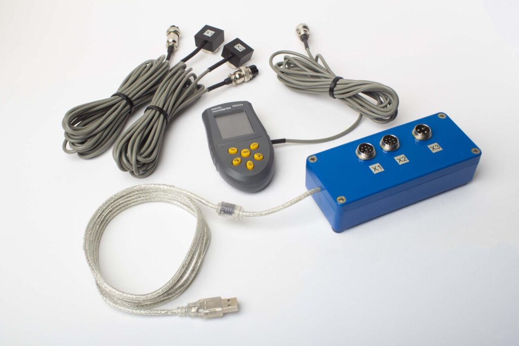
ਪੂਰੇ ਕਿੱਟ ਵਿੱਚ ਕੀ ਸ਼ਾਮਲ ਹੈ
€1,975 · ਪੂਰਾ ਕਿੱਟ, ਸਟਾਕ ਵਿੱਚ, VAT ਇਨਵੌਇਸ
- ਇੰਟਰਫੇਸ ਮਾਪ ਇਕਾਈ (USB, 2 ਚੈਨਲ)
- ਦੋ ਵਾਈਬ੍ਰੇਸ਼ਨ ਐਕਸੇਲੇਰੋਮੀਟਰ (4 m ਕੇਬਲ, 10 m ਵਿਕਲਪਿਕ)
- ਲੇਜ਼ਰ ਟੈਕੋਮੀਟਰ / ਆਪਟੀਕਲ ਫੇਜ਼ ਸੈਂਸਰ (50–500 mm)
- ਸੈਂਸਰ ਲਈ ਮੈਗਨੈਟਿਕ ਸਟੈਂਡ
- ਟਰਾਇਲ & ਸੁਧਾਰ ਵਜ਼ਨ ਲਈ ਡਿਜੀਟਲ ਸਕੇਲ
- Windows ਬੈਲੇਂਸਿੰਗ & ਵਿਸ਼ਲੇਸ਼ਣ ਸੌਫ਼ਟਵੇਅਰ
- ਪਲਾਸਟਿਕ ਟਰਾਂਸਪੋਰਟ ਕੇਸ
ਪੂਰੀ ਕਿੱਟ
ਇਕਾਈ · 2 ਸੈਂਸਰ · ਲੇਜ਼ਰ ਟੈਕੋਮੀਟਰ · ਮੈਗਨੈਟਿਕ ਸਟੈਂਡ · ਡਿਜੀਟਲ ਸਕੇਲ · ਸੌਫ਼ਟਵੇਅਰ · ਟਰਾਂਸਪੋਰਟ ਕੇਸ। ਬਾਕਸ ਤੋਂ ਬਾਹਰ ਬੈਲੇਂਸਿੰਗ ਸ਼ੁਰੂ ਕਰਨ ਲਈ ਸਭ ਕੁਝ ਲੋੜੀਂਦਾ।
OEM ਸੈੱਟ
ਇਕਾਈ · 2 ਸੈਂਸਰ · ਲੇਜ਼ਰ ਟੈਕੋਮੀਟਰ · ਸੌਫ਼ਟਵੇਅਰ। ਉਹਨਾਂ ਇੰਟੀਗ੍ਰੇਟਰਾਂ ਲਈ ਜਿਨ੍ਹਾਂ ਕੋਲ ਪਹਿਲਾਂ ਤੋਂ ਸਟੈਂਡ, ਸਕੇਲ ਅਤੇ ਕੇਸ ਹੈ, ਜਾਂ ਜੋ ਇਕਾਈ ਨੂੰ ਬੈਲੇਂਸਿੰਗ ਮਸ਼ੀਨ ਵਿੱਚ ਏਮਬੈੱਡ ਕਰਦੇ ਹਨ।
| ਪੈਰਾਮੀਟਰ | ਮੁੱਲ |
|---|---|
| ਮਾਪ ਚੈਨਲ | 2 (ਸਿੰਗਲ- & ਟੂ-ਪਲੇਨ ਬੈਲੇਂਸਿੰਗ) |
| ਵਾਈਬ੍ਰੇਸ਼ਨ ਵੇਲੋਸਿਟੀ ਰੇਂਜ | 0.2–80 mm/s RMS |
| ਫ੍ਰੀਕੁਐਂਸੀ ਰੇਂਜ | 5–1000 Hz (≤10% amplitude error above 550 Hz) |
| ਮਾਪ ਸ਼ੁੱਧਤਾ | ±5% ਪੂਰੇ ਸਕੇਲ ਦਾ |
| ਵਿਧੀ | 3-ਰਨ ਇਨਫਲੂਐਂਸ-ਕੋਏਫੀਸ਼ੀਐਂਟ (1 ਜਾਂ 2 ਸੁਧਾਰ-ਪਲੇਨ) |
| ਵਿਸ਼ਲੇਸ਼ਣ | 1× 'ਤੇ ਐਂਪਲੀਟਿਊਡ & ਫੇਜ਼, FFT ਸਪੈਕਟ੍ਰਮ & ਵੇਵਫਾਰਮ, ਸੁਰੱਖਿਅਤ ਰਿਪੋਰਟਾਂ |
| ਲੈਪਟਾਪ | ਸ਼ਾਮਲ ਨਹੀਂ (Windows PC, ਬੇਨਤੀ 'ਤੇ ਉਪਲਬਧ) |
ਫੀਲਡ ਬੈਲੇਂਸਿੰਗ ਬਨਾਮ ਬੈਲੇਂਸਿੰਗ ਮਸ਼ੀਨ — ਤੁਹਾਡੇ ਐਗਜ਼ੌਸਟਰ ਲਈ ਕਿਹੜਾ ਸਹੀ ਹੈ?
| ਫੈਕਟਰ | ਫੀਲਡ ਬੈਲੇਂਸਿੰਗ (Balanset-1A) | ਬੈਲੇਂਸਿੰਗ ਮਸ਼ੀਨ (ਵਰਕਸ਼ਾਪ) |
|---|---|---|
| ਇੰਪੈਲਰ ਹਾਊਸਿੰਗ ਤੋਂ ਹਟਾਇਆ ਗਿਆ? | ਨਹੀਂ — ਆਪਣੀ ਥਾਂ 'ਤੇ ਚੱਲਦਾ ਹੈ | ਹਾਂ — ਪੂਰੀ ਵੱਖ ਕਰਨ ਦੀ ਲੋੜ ਹੈ |
| ਡਕਟਵਰਕ ਡਿਸਕਨੈਕਸ਼ਨ? | ਨਹੀਂ | ਹਾਂ |
| ਉਤਪਾਦਨ ਬੰਦ ਸਮਾਂ | ਸਿਰਫ਼ ਸੈਂਸਰ ਲਗਾਉਣਾ (<15 ਮਿੰਟ) | ਘੰਟਿਆਂ ਤੋਂ ਦਿਨਾਂ ਤੱਕ (ਵੱਖ ਕਰਨਾ, ਢੋਆ-ਢੁਆਈ, ਸੰਤੁਲਨ, ਮੁੜ-ਸਥਾਪਨਾ) |
| ਬੈਲੇਂਸਿੰਗ ਗਤੀ | ਅਸਲ ਕਾਰਜਸ਼ੀਲ ਸਪੀਡ ਅਤੇ ਪ੍ਰਕਿਰਿਆ ਹਾਲਾਤ | ਵੱਖਰਾ ਘੱਟ-ਗਤੀ ਸਪਿੰਡਲ |
| ਥਰਮਲ ਵਿਗਾੜ ਅਤੇ ਜਮ੍ਹਾਂ ਹੋਏ ਪਦਾਰਥਾਂ ਨੂੰ ਧਿਆਨ ਵਿੱਚ ਰੱਖਦਾ ਹੈ | ਹਾਂ — ਪੂਰੀ ਅਸੈਂਬਲੀ ਚੱਲਦੀ-ਹਾਲਤ ਵਿੱਚ ਸੰਤੁਲਿਤ | ਨਹੀਂ — ਸਿਰਫ਼ ਸਾਫ਼ ਕੀਤਾ, ਠੰਢਾ ਇੰਪੈਲਰ |
| ਖੋਰ-ਪ੍ਰੇਰਿਤ ਮੁੜ-ਅਸੰਤੁਲਨ ਨੂੰ ਸੰਭਾਲਦਾ ਹੈ | ਹਾਂ — ਬਿਨਾਂ ਹਟਾਏ, ਸਾਈਟ ਤੇ ਦੁਹਰਾਓ | ਹਰ ਵਾਰ ਪੂਰੀ ਤਰ੍ਹਾਂ ਬਾਹਰ ਕੱਢਣ ਦੀ ਲੋੜ ਹੁੰਦੀ ਹੈ |
| ਪੂਰੇ ਕੀਤੇ ਗਏ ਮਿਆਰ | ISO 14694, ISO 21940-11 | ISO 21940-11 |
| ਉਪਕਰਣ ਦੀ ਲਾਗਤ | €1,975 (ਪੂਰਾ ਕਿੱਟ) | €10,000 – €50,000+ |
| ਆਮ ਕੰਮ ਦਾ ਸਮਾਂ | ਸਾਈਟ 'ਤੇ <1 ਘੰਟਾ | ਕੁੱਲ 1–3 ਦਿਨ |
ਫੀਲਡ ਬੈਲੇਂਸਿੰਗ ਐਗਜ਼ੌਸਟਰਾਂ ਲਈ ਤਰਜੀਹੀ ਵਿਕਲਪ ਹੈ ਜਦੋਂ ਵੀ ਪੱਖਾ ਚੱਲ ਸਕਦਾ ਹੈ ਅਤੇ ਰੋਟਰ ਦੀ ਕਠੋਰਤਾ ਦਾ ਮਾਪਦੰਡ ਪੂਰਾ ਹੁੰਦਾ ਹੈ — ਜੋ ਕਿ ਆਪਣੀ ਪਹਿਲੀ ਕ੍ਰਿਟੀਕਲ ਸਪੀਡ ਤੋਂ ਹੇਠਾਂ ਚੱਲ ਰਹੇ ਜ਼ਿਆਦਾਤਰ ਉਦਯੋਗਿਕ ਇੰਪੈਲਰਾਂ ਦੇ ਮਾਮਲੇ ਵਿੱਚ ਹੁੰਦਾ ਹੈ। ਵਰਕਸ਼ਾਪ ਮਸ਼ੀਨ ਨਵੇਂ-ਨਿਰਮਿਤ ਇੰਪੈਲਰਾਂ ਲਈ ਢੁਕਵੀਂ ਰਹਿੰਦੀ ਹੈ ਜਿਨ੍ਹਾਂ ਦਾ ਕੋਈ ਚਾਲੂ ਸਮਾਂ ਨਹੀਂ ਹੈ, ਜਾਂ ਹੋਰ ਕਾਰਨਾਂ ਕਰਕੇ ਮੁਰੰਮਤ ਕੀਤੇ ਜਾ ਰਹੇ ਬਹੁਤ ਵੱਡੇ ਰੋਟਰਾਂ ਲਈ।
ਅਸਲ ਐਗਜ਼ੌਸਟਰ ਬੈਲੇਂਸਿੰਗ ਕੇਸ
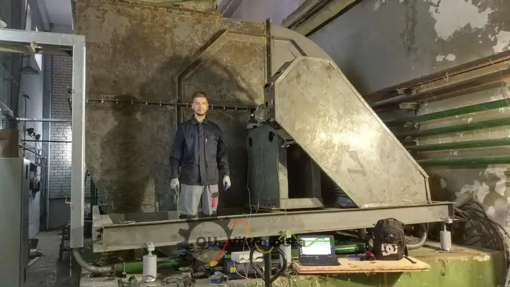
ਉਦਯੋਗਿਕ ਐਗਜ਼ੌਸਟਰ
ਕਾਰਜਸ਼ੀਲ ਹਾਲਤਾਂ ਵਿੱਚ ਉਦਯੋਗਿਕ ਐਗਜ਼ੌਸਟਰ ਪੱਖਿਆਂ ਦੀ ਇਨ-ਸਿਟੂ ਸੰਤੁਲਨ, ਪਹਿਲਾਂ ਅਤੇ ਬਾਅਦ ਦੇ ਵਾਈਬ੍ਰੇਸ਼ਨ ਡਾਟੇ ਦੇ ਨਾਲ।
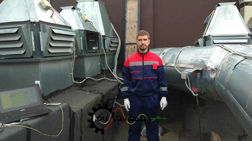
ਸਾਈਟ 'ਤੇ ਐਗਜ਼ਾਸਟ ਫੈਨ
Balanset-1A ਦੀ ਵਰਤੋਂ ਕਰਦਿਆਂ ਪੂਰੇ ਵਾਈਬ੍ਰੇਸ਼ਨ ਮਾਪ ਅਤੇ ਫੇਜ਼ ਵਿਸ਼ਲੇਸ਼ਣ ਦੇ ਨਾਲ ਐਗਜ਼ੌਸਟ ਫੈਨ ਦੀ ਆਨ-ਸਾਈਟ ਸੰਤੁਲਨ।
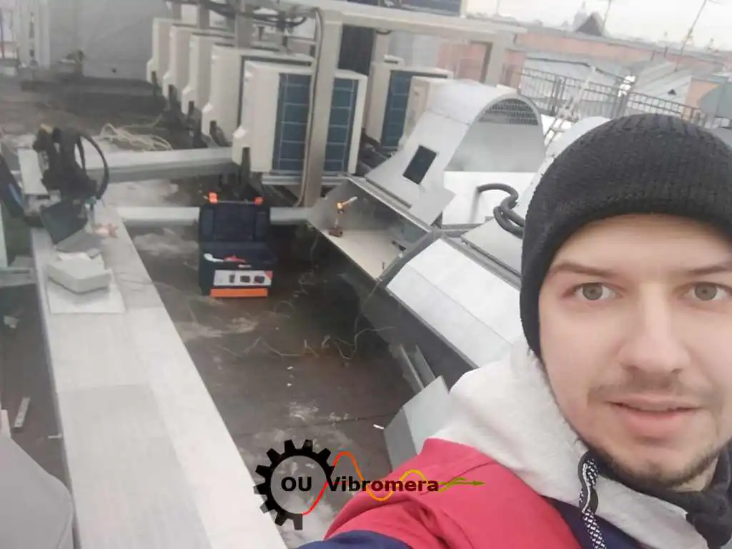
HVAC ਐਗਜ਼ੌਸਟ ਫੈਨ ਇੰਪੈਲਰ
ਸੈਂਸਰ ਮਾਊਂਟਿੰਗ ਤੋਂ ਲੈ ਕੇ ਅੰਤਿਮ ਪੁਸ਼ਟੀ ਤੱਕ ਦਸਤਾਵੇਜ਼ੀਕਰਨ ਕੀਤੀ ਗਈ, HVAC ਅਤੇ ਵੈਂਟੀਲੇਸ਼ਨ ਐਗਜ਼ੌਸਟ ਫੈਨ ਇੰਪੈਲਰ ਦੀ ਕਦਮ-ਦਰ-ਕਦਮ ਫੀਲਡ ਬੈਲੇਂਸਿੰਗ।
ਮੁਫ਼ਤ ਐਗਜ਼ੌਸਟਰ ਅਤੇ ਫੈਨ ਕੈਲਕੁਲੇਟਰ
ਐਗਜ਼ੌਸਟਰ ਬੈਲੇਂਸਿੰਗ ਸੰਬੰਧੀ ਅਕਸਰ ਪੁੱਛੇ ਜਾਂਦੇ ਸਵਾਲ
ਕੀ ਗਰਮ, ਧੂੜ ਭਰੀ ਜਾਂ ਖੋਰਦਾਰ ਗੈਸ ਸੰਭਾਲਦੇ ਹੋਏ ਐਗਜ਼ੌਸਟਰਾਂ ਨੂੰ ਸੰਤੁਲਿਤ ਕੀਤਾ ਜਾ ਸਕਦਾ ਹੈ?
ਸਾਡੇ ਐਗਜ਼ੌਸਟਰ ਵਿੱਚ ਸਕੇਲ ਜਮ੍ਹਾਂ ਹੁੰਦਾ ਹੈ ਜੋ ਰੋਟਰ ਨੂੰ ਜਲਦੀ ਮੁੜ-ਅਸੰਤੁਲਿਤ ਕਰ ਦਿੰਦਾ ਹੈ — ਅਸੀਂ ਇਸ ਨੂੰ ਕਿਵੇਂ ਸੰਭਾਲੀਏ?
ਕੀ ਇੱਕ ਸੁਧਾਰ ਪਲੇਨ ਕਾਫ਼ੀ ਹੈ, ਜਾਂ ਸਾਨੂੰ ਦੋ ਦੀ ਲੋੜ ਹੈ?
ਜੇ ਸੰਤੁਲਨ ਕਰਨ ਤੋਂ ਬਾਅਦ ਵਾਈਬ੍ਰੇਸ਼ਨ ਜਲਦੀ ਵਾਪਸ ਆ ਜਾਵੇ ਤਾਂ ਕੀ?
ਕੀ Balanset-1A ਵੱਡੇ, ਭਾਰੀ ਐਗਜ਼ੌਸਟਰ ਪੱਖਿਆਂ ਤੇ ਕੰਮ ਕਰਦਾ ਹੈ?
ਐਗਜ਼ੌਸਟਰ ਪੱਖਿਆਂ ਨੂੰ ਕਿਹੜੇ ਸੰਤੁਲਨ ਗ੍ਰੇਡ ਨੂੰ ਪੂਰਾ ਕਰਨ ਦੀ ਲੋੜ ਹੈ?
ਸਿਧਾਂਤ ਸਿੱਖੋ
ਐਗਜ਼ੌਸਟਰ ਬੇਅਰਿੰਗਾਂ ਨੂੰ ਬਦਲਣਾ ਬੰਦ ਕਰੋ — ਰੋਟਰ ਨੂੰ ਥਾਂ ਤੇ ਹੀ ਸੰਤੁਲਿਤ ਕਰੋ
Balanset-1A ਐਗਜ਼ੌਸਟਰਾਂ, ਡਸਟ ਐਕਸਟਰੈਕਟਰਾਂ ਅਤੇ ਇੰਡਿਊਸਡ-ਡਰਾਫਟ ਪੱਖਿਆਂ ਦਾ ਚਾਲੂ ਸਪੀਡ ਤੇ, ਅਸਲ ਪ੍ਰਕਿਰਿਆ ਹਾਲਾਤਾਂ ਵਿੱਚ ਸਿੰਗਲ- ਅਤੇ ਦੋ-ਪਲੇਨ ਇਨ-ਸਿਟੂ ਸੰਤੁਲਨ ਕਰਦਾ ਹੈ। ਕੋਈ ਇੰਪੈਲਰ ਹਟਾਉਣਾ ਨਹੀਂ, ਕੋਈ ਡਕਟ ਡਿਸਕਨੈਕਸ਼ਨ ਨਹੀਂ — ਬਸ ਇੱਕ ਸ਼ਾਂਤ, ਲੰਬੇ ਸਮੇਂ ਤੱਕ ਚੱਲਣ ਵਾਲਾ ਪੱਖਾ ISO 14694 ਅਤੇ ISO 21940-11 ਅਨੁਸਾਰ ਦਸਤਾਵੇਜ਼ੀਕਰਨ ਕੀਤੇ ਬਾਕੀ-ਅਸੰਤੁਲਨ ਅੰਕੜਿਆਂ ਦੇ ਨਾਲ।
