Pengukuran getaran rotor relatif menggunakan penderia pemindahan lurus tanpa sentuhan
Dengan Balanset-1A anda boleh mengukur relatif getaran daripada pemutar menggunakan pengkod linear tanpa sentuhan.
1.1 Pemilihan jenis sensor dan tetapan
Bergantung pada tugas, sama ada sensor getaran atau sensor pemindahan boleh digunakan untuk pengukuran. Untuk memilih jenis sensor, pada panel “Jenis Sensor” (di bahagian bawah tetingkap utama) tandakan kotak “Vibro” atau “Linear”.
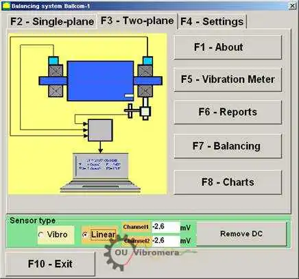
Rajah 1. Tetingkap kerja utama program Balanset.T
Before starting the measurement it is necessary to make sure that the conversion coefficients of the sensors are set correctly. For this purpose press the button “F4-Settings” in the main working window of the program (see Fig. 1) and go to the settings window designed for entering conversion coefficients (see Fig. 2).
Dalam tetingkap kerja yang ditunjukkan dalam Rajah 2, dalam medan yang sepadan hendaklah dimasukkan pekali penukaran bagi penderia linear dan getaran. Pekali ini dinyatakan dalam pasport instrumen. Biasanya anda tidak perlu mengubahnya.
Untuk yang linear anjakan Untuk penderia yang digunakan dalam set instrumen Balanset-1A, pekali penukaran masing-masing adalah sama dengan:
- Kprl1= 0.94 mV/μm (koefisien penukaran sensor saluran ke-1);
- Kprl2 = 0.94 mV/μm (koefisien penukaran sensor saluran ke-2).
For proper operation, the linear encoder must be installed at a certain distance from the surface of the object of measurement. The nominal clearance between the surface and the end of the sensor is 3.5 mm. In this case there is a constant voltage of 2.48 volts at the sensor output. This voltage will be shown in the fields “Channel1” and “Channel2” for the first and second channels respectively.
To compensate it you must press the button “Remove DC”. A small residual offset will not interfere with the measurement.
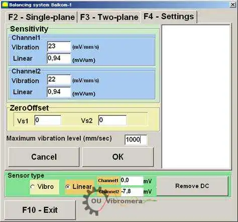
Rajah 2. Tetingkap kerja untuk memasukkan pekali penukaran dan memilih jenis sensor yang digunakan
Perhatian! Nilai celah nominal dan faktor penukaran enkoder linear yang dinyatakan diberikan untuk rotor yang diperbuat daripada keluli. Bagi rotor yang diperbuat daripada logam lain (tembaga, gangsa, aluminium), celah nominal dan koefisien penukaran sensor perlu ditentukan secara eksperimen oleh pengguna melalui kalibrasi.
To save the changed parameters press “OK” button. The new parameters will be saved in a file and used for further measurements.
1.2 Mengukur run-out jejari rotor
Rentangan radial rotor boleh diukur secara tanpa sentuhan. probe kedekatan dalam dua satah mengikut skema yang ditunjukkan dalam Rajah 3. Untuk mengukur dan melukis fungsi masa dan spektrum larian rotor, jika perlu, beberapa operasi persediaan mesti dijalankan, termasuk:
- – select diametrical sections of the rotor, in which the measurements will be carried out;
- untuk memasang penderia pemindahan lurus tanpa sentuhan 5 dan 6 dan fasa penderia sudut 7 pada katil mesin menggunakan peranti khas (contohnya tripod magnetik);
- – connect proximity sensors of linear motion to connectors X1 and X2, and phase angle sensor to connector X3 of the measuring unit;
- – set a nominal measuring gap ∆ between the rotor surface and the sensing element for each linear encoder (for the rotor made of steel ∆ = 3.5 mm);
- – place on the rotor the reflective mark required for triggering for the phase angle sensor 7 and check the sensor triggering;
- Sambungkan unit pengukur ke komputer.
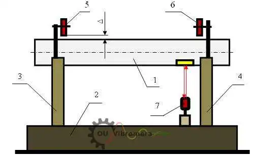
Rajah 3. Mengukur lari radial rotor
If you press the button “F8 – Charts” in the main working window (see Fig. 1), the computer display shows the working window “Graphs” (see Fig. 5), designed to build different kinds of graphs of radial run-out of the rotor.
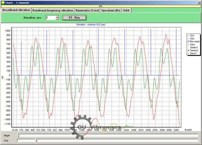
Fig. 5. The working window of the “Charts” mode
Butang-butang dalam tetingkap ini membina graf berikut:
- When you press the “Broadband vibration” button in this window, the time function of the rotor radial runout is displayed.
- If the “Rotation frequency vibration” button is pressed, the time function of the reciprocal component of the rotor radial runout is displayed.
- If you press the button “Harmonics (1/rev)”, the display will show a decomposition graph of the rotor runout into a harmonic series. The first harmonic corresponds to the value of vibration at the reverse rotor frequency (1x), the second one – at the double frequency (2x), etc.
- By pressing the button “Spectrum (Hz)” the display shows the spectrum of the radial run-out of the rotor.
- By pressing the button “Orbit” the graph of rotor orbit (precession) is displayed.
1.3 Pembinaan graf orbit rotor
Pembinaan graf orbit rotor boleh dilakukan mengikut skema yang ditunjukkan dalam Rajah 6.
Fig. 6. Scheme of rotor orbit measurement 1a – rotor (end view); 1b – rotor (side view); 2, 3 – non-contact sensors; 4 – reflection mark of phase angle sensor.
Untuk membuat pengukuran dan membina graf yang sepadan, adalah perlu untuk melaksanakan beberapa operasi persediaan, termasuk:
- – install the non-contact linear encoders 2 and 3 in one of the diametrical sections of the rotor at an angle of 90° to each other, provided that the measuring axis of encoder 2 must coincide with the X axis, and the measuring axis of encoder 3 must coincide with the Y axis;
- tetapkan jurang pengukuran nominal ∆x (∆y) antara permukaan rotor dan elemen penderia setiap pengekod linear (untuk keluli ∆ = 3.5 mm);
- – set the phase angle sensor (not shown in the scheme) in the X – Z plane, coinciding with the installation plane of non-contact sensor 2;
- – set a reflective mark 4 on the rotor 1 in the X – Z plane, which is necessary for the phase angle sensor operation;
- – connect non-contact linear encoders 2 and 3 to connectors X1 and X2, and phase angle encoder to connector X3 of the measuring unit;
- Sambungkan unit pengukur ke komputer.
Untuk memulakan pengukuran orbit rotor dalam tetingkap kerja utama (lihat Rajah 1), tekan butang “F8 – Carta” dan pergi ke tetingkap kerja “Graf” (lihat Rajah 5), yang direka untuk membina pelbagai jenis graf larian radial rotor. Dalam tetingkap kerja ini anda mesti menekan butang “Orbit”, selepas itu tetingkap kerja akan muncul pada skrin komputer, di mana kitaran pengukuran yang diperlukan dijalankan (lihat Rajah 7).
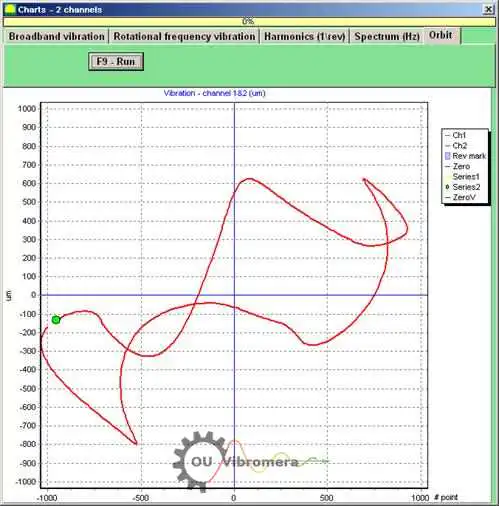
Rajah 7. Graf orbit rotor. Perisian Balanset.
Untuk meneruskan kerja dalam tetingkap kerja yang ditetapkan (lihat Rajah 7) anda mesti menghidupkan putaran rotor dan dengan menekan butang “F9 – RUN” melakukan pengukuran nilai seketika lari keluar jejari rotor Sxi dan Syi bagi tempoh yang bersamaan dengan satu pusingan rotor.
Susunan nilai seketika Sxi dan Syi yang diperoleh semasa pengukuran digunakan untuk memplot orbit rotor yang dikawal (setiap titik ke-i orbit mempunyai koordinat Sxi, Syi). Magnitud sesaran jejari seketika dikira dengan formula:
S∑i = √ (Sxi² + Syi²) (1)
di mana S∑i ialah nilai seketika magnitud sesaran jejari (panjang vektor jejari orbit rotor), yang dikira untuk titik ke-i graf;
- Sxi – nilai seketika lari keluar jejari rotor, diukur sepanjang paksi X dengan sensor 2 (lihat Rajah 6) pada titik ke-i;
- Syi – nilai seketika lari keluar jejari rotor, diukur sepanjang paksi Y dengan sensor 3 (lihat Rajah 6) pada titik ke-i.