Kontaktdan asılı olmayan xətti yer dəyişmə sensorlarından istifadə edərək nisbətən rotor vibrasiyasının ölçülməsi
ilə Balanset-1A siz nisbi vibrasiyani olce bilersiniz vibrasiya rotorun rotor Kontaktdan istifadə etməyən xətti enkoderlərdən istifadə edərək.
1.1 Sensor növünün və parametrlərinin seçilməsi
Vəzifədən asılı olaraq ölçmələr üçün ya vibrasiya sensorları, ya da yer dəyişmə sensorları istifadə oluna bilər. Sensor növünü seçmək üçün əsas pəncərənin aşağısındakı “Sensor növü” panelində “Vibro” və ya “Xətti” qutusuna işarə qoymaq lazımdır.
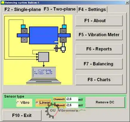
Şəkil 1. Balanset proqramının əsas iş pəncərəsi.T
Before starting the measurement it is necessary to make sure that the conversion coefficients of the sensors are set correctly. For this purpose press the button “F4-Settings” in the main working window of the program (see Fig. 1) and go to the settings window designed for entering conversion coefficients (see Fig. 2).
Şəkil 2-də göstərilən iş pəncərəsində müvafiq sahələrə xətti və vibrasiya sensorlarının çevirmə əmsalları daxil edilməlidir. Bu əmsallar cihazın pasportunda göstərilir. Adətən onları dəyişdirməyə ehtiyac olmur.
Xətti üçün yerdəyişmə Balanset-1A alətinin dəstində istifadə olunan sensorlar üçün çevirmə əmsalları müvafiq olaraq bərabərdir:
- Kprl1= 0.94 mV/μm (1-ci kanalın sensorunun çevirmə əmsalı);
- Kprl2 = 0.94 mV/μm (2-ci kanalın sensorunun çevirmə əmsalı)
For proper operation, the linear encoder must be installed at a certain distance from the surface of the object of measurement. The nominal clearance between the surface and the end of the sensor is 3.5 mm. In this case there is a constant voltage of 2.48 volts at the sensor output. This voltage will be shown in the fields “Channel1” and “Channel2” for the first and second channels respectively.
To compensate it you must press the button “Remove DC”. A small residual offset will not interfere with the measurement.
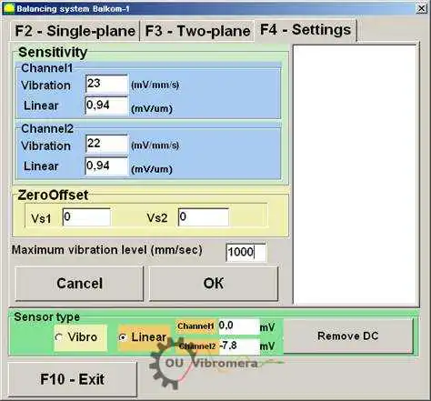
Şəkil 2. Çevirmə əmsallarını daxil etmək və istifadə olunan sensorların növünü seçmək üçün iş pəncərəsi
Diqqət! Nominal boşluq dəyərləri və xətti enkoderlərin çevirmə əmsalları poladdan hazırlanmış rotorlar üçün göstərilmişdir. Mis, bürünc və ya alüminiumdan hazırlanmış rotorlarda nominal boşluq və sensorların çevirmə əmsalları istifadəçi tərəfindən kalibrləmə aparmaqla eksperimental yolla müəyyən edilməlidir.
To save the changed parameters press “OK” button. The new parameters will be saved in a file and used for further measurements.
1.2 Rotorun radial yayılmasının ölçülməsi
Rotorun radial sapması kontaktdan istifadə etmədən ölçülə bilər. yaxınlıq zondları Şəkil 3-də göstərilən sxemə əsasən iki müstəvidə. Zaman funksiyasını və rotorun yayılma spektrini ölçmək və qrafik üzərində göstərmək üçün, lazım gəldikdə, bir sıra hazırlıq işləri aparılmalıdır, o cümlədən:
- – select diametrical sections of the rotor, in which the measurements will be carried out;
- 5 və 6 saylı kontaktdan asılı olmayan xətti yerləşmə sensorlarını quraşdırmaq və faza maşının çarpayısına xüsusi qurğular (məsələn, maqnit tripodları) istifadə edərək bucaq sensor 7-ni;
- – connect proximity sensors of linear motion to connectors X1 and X2, and phase angle sensor to connector X3 of the measuring unit;
- – set a nominal measuring gap ∆ between the rotor surface and the sensing element for each linear encoder (for the rotor made of steel ∆ = 3.5 mm);
- – place on the rotor the reflective mark required for triggering for the phase angle sensor 7 and check the sensor triggering;
- Ölçmə qurğusunu kompüterə qoşun.
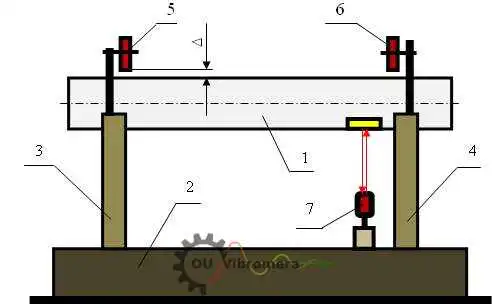
Şəkil 3. Rotorun radial sapmasını ölçmə
Əsas iş pəncərəsində (bax Şəkil 1) “F7 – Charts” düyməsini bassanız, kompüter ekranında rotorun radial çıxışının müxtəlif növ qrafiklərini qurmaq üçün nəzərdə tutulmuş “Graphs” iş pəncərəsi göstərilir (bax Şəkil 5).
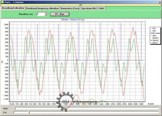
Fig. 5. The working window of the “Charts” mode
Bu pəncərədəki düymələr aşağıdakı qrafikləri qurur:
- When you press the “Broadband vibration” button in this window, the time function of the rotor radial runout is displayed.
- If the “Rotation frequency vibration” button is pressed, the time function of the reciprocal component of the rotor radial runout is displayed.
- If you press the button “Harmonics (1/rev)”, the display will show a decomposition graph of the rotor runout into a harmonic series. The first harmonic corresponds to the value of vibration at the reverse rotor frequency (1x), the second one – at the double frequency (2x), etc.
- By pressing the button “Spectrum (Hz)” the display shows the spectrum of the radial run-out of the rotor.
- By pressing the button “Orbit” the graph of rotor orbit (precession) is displayed.
1.3 Rotor orbit qrafının qurulması
Rotor orbit qrafının qurulması 6-cı fiqurda göstərilən sxemə uyğun olaraq həyata keçirilə bilər.
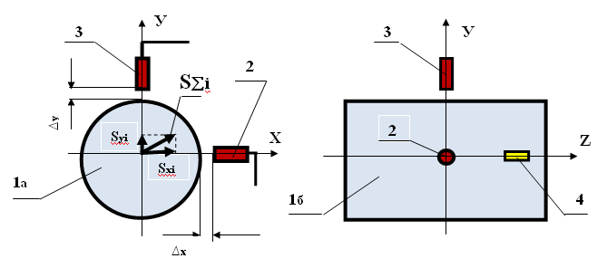
Fig. 6. Scheme of rotor orbit measurement 1a – rotor (end view); 1b – rotor (side view); 2, 3 – non-contact sensors; 4 – reflection mark of phase angle sensor.
Ölçü aparmaq və müvafiq qrafik qurmaq üçün bir sıra hazırlıq əməliyyatları aparmaq lazımdır, o cümlədən:
- – install the non-contact linear encoders 2 and 3 in one of the diametrical sections of the rotor at an angle of 90° to each other, provided that the measuring axis of encoder 2 must coincide with the X axis, and the measuring axis of encoder 3 must coincide with the Y axis;
- hər bir xətti enkoderin həssas elementi ilə rotor səthi arasında nominal ölçmə boşluğunu ∆x (∆y) təyin edin (polad üçün ∆ = 3.5 mm);
- – set the phase angle sensor (not shown in the scheme) in the X – Z plane, coinciding with the installation plane of non-contact sensor 2;
- Faza bucağı sensörünün işləməsi üçün rotor 1-də X–Z müstəvisində 4 nömrəli əks etdirici işarə qoyun;
- – connect non-contact linear encoders 2 and 3 to connectors X1 and X2, and phase angle encoder to connector X3 of the measuring unit;
- Ölçmə qurğusunu kompüterə qoşun.
Rotor orbitinin ölçülməsinə başlamaq üçün əsas iş pəncərəsində (bax Şəkil 1) “F7 – Charts” düyməsini basın və rotorun radial çıxışının müxtəlif növ qrafiklərini qurmaq üçün nəzərdə tutulmuş “Graphs” iş pəncərəsinə keçin (bax Şəkil 5). Bu iş pəncərəsində “Orbit” düyməsini basmalısınız, bundan sonra kompüter ekranında lazımi ölçmə dövrünün aparıldığı iş pəncərəsi görünür (bax Şəkil 7).
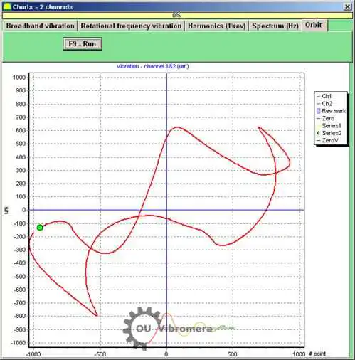
Şək.7. Rotor orbitinin qrafiki. Balanset proqramı.
Göstərilən iş pəncərəsində işi davam etdirmək üçün (bax. Şək. 7) rotorun fırlanmasını işə salmalı və “F9 – RUN” düyməsini basaraq bir rotor dövrünə bərabər müddət ərzində rotorun radial qaçmasının ani Sxi və Syi qiymətlərini ölçməlisiniz.
Ölçmə zamanı əldə edilən ani Sxi və Syi qiymətləri massivi idarə olunan rotorun orbitini qurmaq üçün istifadə olunur (orbitin hər i-ci nöqtəsi Sxi, Syi koordinatlarına malikdir). Ani radial yerdəyişmənin modulu aşağıdakı düsturla hesablanır:
S∑i = √ (Sxi² + Syi²) (1)
burada S∑i qrafikin i-ci nöqtəsi üçün hesablanmış ani radial yerdəyişmə moduludur (rotor orbitinin radius-vektorunun uzunluğu);
- Sxi – rotorun radial qaçmasının ani qiyməti, i-ci nöqtədə X oxu boyunca 2-ci sensorla ölçülmüşdür (bax. Şək. 6);
- Syi – rotorun radial qaçmasının ani qiyməti, i-ci nöqtədə Y oxu boyunca 3-cü sensorla ölçülmüşdür (bax. Şək. 6).

Nikolai Shelkovenko
Nikolai Shelkovenko vibrasiya təhlili mühəndisi, həmçinin Vibromera şirkətinin təsisçisi və baş direktorudur. 15 ildən artıqdır ki, o, fırlanan avadanlığı sınaq stendində deyil, sahədə balanslaşdırır: malçlayıcılar, sənaye ventilyatorları, qırıcılar, sentrifuqalar, vallar və işçi millər. Məhz bu işdən Balanset cihazları yarandı — onlar mütəxəssisin maşının yanına apara biləcəyi və yerində təkbaşına istifadə edə biləcəyi alət kimi hazırlanıb, laboratoriya avadanlığı kimi yox. Vibromera 2017-ci ildə təsis edilib və 2023-cü ildən Portuqaliyanın Porto şəhərində yerləşir. Balanset xəttinin işlənməsi, yığılması və dəstəyi burada həyata keçirilir. Flaqman cihaz Balanset-1A-dır — bir və iki müstəvidə balanslaşdırma, həmçinin vibrasiya diaqnostikası üçün portativ analizator. Nikolai müştəri dəstəyində, mürəkkəb balanslaşdırma hallarının həllində və proqram təminatının hazırlanmasında şəxsən iştirak edir. O, dünyanın hər yerindən olan müştərilərlə, istənilən dildə işləyir.

