Produtos
-
 Balanceador portátil & Analisador de vibração Balanset-1A
€1,975.00 – €2,025.00Price range: €1,975.00 through €2,025.00 + IVA (se aplicável)
Balanceador portátil & Analisador de vibração Balanset-1A
€1,975.00 – €2,025.00Price range: €1,975.00 through €2,025.00 + IVA (se aplicável)
-
 Balanceador dinâmico “Balanset-1A” OEM
€1,735.00 + IVA (se aplicável)
Balanceador dinâmico “Balanset-1A” OEM
€1,735.00 + IVA (se aplicável)
-
 Sensor de vibração
€90.00 – €110.00Price range: €90.00 through €110.00 + IVA (se aplicável)
Sensor de vibração
€90.00 – €110.00Price range: €90.00 through €110.00 + IVA (se aplicável)
-
 Sensor Óptico (Tacômetro a Laser)
€124.00 – €144.00Price range: €124.00 through €144.00 + IVA (se aplicável)
Sensor Óptico (Tacômetro a Laser)
€124.00 – €144.00Price range: €124.00 through €144.00 + IVA (se aplicável)
-
 Balanset-4
€6,803.00 + IVA (se aplicável)
Balanset-4
€6,803.00 + IVA (se aplicável)
Balanceamento de Bomba Hidráulica com o Dispositivo Balanset-1A
Um guia prático para engenheiros e técnicos de manutenção, cobrindo tecnologia de balanceamento dinâmico usando o dispositivo portátil Balanset-1A
1. Finalidade e Princípio de Funcionamento
O balanceamento de bombas hidráulicas é um procedimento para eliminar o desbalanceamento das partes rotativas, reduzindo a vibração e aumentando a vida útil do equipamento.
O processo de balanceamento envolve medir a vibração e a fase do rotor, adicionando ou removendo pequenas massas de correção no impelidor ou no eixo. Ao contrariar a distribuição desigual de massa, este procedimento reduz significativamente as forças centrífugas que causam vibração e danos potenciais.
Principais causas de desbalanceamento:
- Imprecisões de fabricação do impelidor e do eixo
- Desgaste e danos durante a operação
- Danos por corrosão e cavitação
- Montagem incorreta após reparo
Consequências do desbalanceamento:
- Aumento da vibração e do ruído
- Desgaste acelerado dos rolamentos e das vedações
- Redução da eficiência da bomba
- Risco de falha de emergência
2. Descrição Técnica do Balanset-1A
Balanset-1A é um dispositivo portátil de dois canais para balanceamento dinâmico de rotores diretamente no local de trabalho (in situ).
Estrutura do Sistema Balanset-1A
Especificações técnicas
| Parâmetro | Valor | Unidade |
|---|---|---|
| Faixa de medição de velocidade de vibração (RMS) | 0.02 - 80 | mm/s |
| Faixa de frequência | 5 - 1000 | Hz |
| Faixa de medição de velocidade rotacional | 100 - 100,000 | rpm |
| Precisão de medição de fase | ±1 | grau |
| Número de planos de correção | 1 ou 2 | - |
| Temperatura de operação | +5...+50 | °C |
Conteúdo da embalagem do dispositivo
Interface USB com pré-amplificadores e ADC
2 acelerômetros com montagem magnética
Sensor de fase com suporte magnético
Para instalação no eixo da bomba
Para medição precisa de peso
Em pen drive com instruções
3. Preparação para o Balanceamento
Instalação do sensor
Diagrama de instalação do sensor na bomba hidráulica
- Instale os sensores de vibração na carcaça da bomba perto dos rolamentos, orientados perpendicularmente ao eixo do eixo
- Fixe fita refletiva no eixo da bomba ou no acoplamento
- Monte o tacômetro a laser em um suporte magnético oposto à fita refletiva
- Conecte os sensores à unidade de medição
- Conecte a unidade de medição ao laptop via USB
4. Procedimento de Balanceamento
O procedimento de balanceamento com o Balanset-1A segue tipicamente um método de três corridas (método dos coeficientes de influência) usando massas de teste. Abaixo está um resumo passo a passo do processo, desde a medição da vibração inicial até a instalação das massas de correção e a verificação dos resultados.
Medição inicial de vibração
- Inicie o software Balanset-1A
- Selecione o modo de balanceamento em um plano ou dois planos
- Ligue a bomba na velocidade de operação
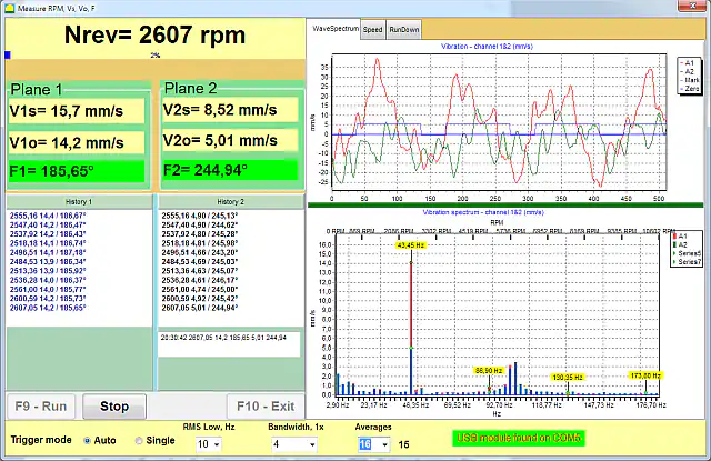
- Pressione "Run#0" no software para medir a vibração inicial
- Registre os valores de amplitude e fase de vibração
Instalação da massa de teste
- Pare a bomba
- Pese uma massa de teste adequada usando a balança eletrônica
- Instale a massa no rotor no primeiro plano de correção
- Insira a massa da massa e o raio de instalação no software
- Reinicie a bomba e execute a medição "Run#1"
Medição do segundo plano (para balanceamento em dois planos)
- Pare a bomba e remova a massa de teste do primeiro plano
- Fixe a massa de teste no segundo plano de correção
- Inicie a bomba e execute a medição "Run#2"
- O software calculará automaticamente as massas de correção necessárias
Instalação da massa de correção
- Pare a bomba e remova quaisquer massas de teste
- Fabrique ou selecione as massas de correção conforme o cálculo do software
- Fixe as massas por soldagem, parafusos ou usando grampos
- O ângulo de instalação de cada massa é medido a partir da posição da massa de teste no sentido de rotação
Medição de verificação
- Operar a bomba na velocidade de funcionamento
- Execute uma medição de controle ("RunTrim")
- Verifique se a vibração foi reduzida para níveis aceitáveis
- Ajuste as massas das massas e repita a medição, se necessário
5. Critérios de Avaliação da Qualidade do Balanceamento
Valores aceitáveis de vibração residual
| Categoria da bomba (ISO 10816-7) | Aceitável para operação de longo prazo (limite da zona B), mm/s RMS | Risco de dano (zona D), mm/s RMS |
|---|---|---|
| Categoria I (serviço de alta confiabilidade), até 200 kW | ≤ 4,0 | > 6,6 |
| Categoria I (serviço de alta confiabilidade), acima de 200 kW | ≤ 5,0 | > 7,6 |
| Categoria II (serviço geral), até 200 kW | ≤ 5,1 | > 8,5 |
| Categoria II (serviço geral), acima de 200 kW | ≤ 6,1 | > 9,5 |
Sinais de balanceamento bem-sucedido
- Redução de 70–90% na vibração na frequência rotacional 1×
- Leituras de fase de vibração estáveis e consistentes
- Ausência de ruído incomum
- Funcionamento suave e uniforme da bomba
6. Recomendações Práticas
Frequência de balanceamento
Balanceamento programado
- Equipamento novo – após o período inicial de rodagem
- Após reparos maiores – obrigatório
- Anualmente para equipamentos críticos
- Quando os níveis de vibração dobram em relação ao valor de referência
Balanceamento não programado
- Ao notar vibração ou ruído incomum
- Após qualquer substituição do impelidor
- Se a vibração exceder os níveis aceitáveis
- Após uma parada de emergência
Requisitos para balanceamento de qualidade
- Certifique-se de que a bomba esteja em bom estado mecânico
- Verifique se a bomba está firmemente montada em uma fundação estável
- Verifique se os rolamentos não têm folga excessiva
- Confirme o alinhamento adequado entre a bomba e o motor
- Mantenha a velocidade de funcionamento estável durante o balanceamento
Documentação dos resultados
- Mantenha um registro de todos os trabalhos de balanceamento realizados
- Salve os relatórios do software Balanset-1A para cada serviço de balanceamento
- Documente a massa e a posição das massas de correção instaladas
- Registre os níveis finais de vibração após o balanceamento (medições de controle)
Conclusão
O dispositivo portátil Balanset-1A fornece balanceamento eficaz de bombas hidráulicas diretamente no local de trabalho. A aplicação adequada desta tecnologia permite aos usuários:
- Reduzir a vibração do equipamento por um fator de 3–10
- Aumentar a vida útil dos rolamentos em 2–5 vezes
- Reduzir o consumo de energia em 5–15%
- Prevenir paradas de emergência
- Diminuir os custos gerais de manutenção
O balanceamento regular de bombas hidráulicas é uma parte importante do sistema de manutenção preventiva planejada para equipamentos industriais.
Perguntas Frequentes (FAQ)
O que é balanceamento de bomba hidráulica?
O balanceamento de bombas hidráulicas é o processo de correção da distribuição desigual de massa nos componentes rotativos de uma bomba (como o impelidor e o eixo). Ao adicionar ou remover pequenas massas, o objetivo é eliminar vibrações e ruídos excessivos, melhorando o desempenho e estendendo a vida útil da bomba.
Por que o balanceamento de uma bomba hidráulica é importante?
O balanceamento de uma bomba é crucial porque uma bomba desbalanceada pode causar vibrações e ruídos excessivos, levando ao desgaste acelerado de rolamentos e vedações, redução da eficiência e aumento do risco de falha súbita. O balanceamento adequado ajuda a garantir o funcionamento suave, eficiente e confiável da bomba.
Como balancear uma bomba hidráulica?
O balanceamento de bombas hidráulicas é normalmente realizado usando um dispositivo como o Balanset-1A. O processo envolve medir a vibração e a fase da bomba, adicionar uma massa de teste ao rotor, medir a mudança e, em seguida, calcular e instalar uma massa de correção em uma localização específica. Após a instalação da massa de correção, a bomba é ligada novamente para verificar se os níveis de vibração caíram para limites aceitáveis.
Que equipamento é usado para balanceamento de bombas?
O balanceamento de bombas requer um sistema de medição de vibração e balanceamento. O kit Balanset-1A, por exemplo, inclui um módulo de interface USB, dois sensores de vibração (acelerômetros), um tacômetro a laser (sensor de referência de fase), fita refletiva para o rotor, balanças eletrônicas para pesar as massas de teste e de correção, e um software especializado executado em um laptop para orientar o procedimento de balanceamento.
Com que frequência uma bomba deve ser balanceada?
As bombas devem ser balanceadas sempre que houver vibração significativa ou após eventos que possam causar desbalanceamento. Recomenda-se balancear bombas novas após um período inicial de rodagem, após reparos maiores ou substituições de impelidor, e como parte da manutenção anual para bombas críticas. O balanceamento não programado é aconselhado se aparecer vibração ou ruído incomum ou após qualquer parada de emergência.
Quais são os níveis de vibração aceitáveis para uma bomba balanceada?
Os níveis de vibração aceitáveis dependem da categoria e potência da bomba. A ISO 10816-7 (bombas rotodinâmicas acima de 1 kW) estabelece limites da zona B — aceitáveis para operação de longo prazo sem restrições — de 4,0 mm/s (RMS) para bombas da Categoria I (alta confiabilidade) até 200 kW e 5,0 mm/s acima de 200 kW; para bombas de serviço geral da Categoria II, os limites são 5,1 mm/s até 200 kW e 6,1 mm/s acima de 200 kW. Vibração acima do limite da zona C/D (6,6–9,5 mm/s dependendo da categoria e potência) indica risco de dano e necessita de atenção imediata.
O balanceamento corrige todos os problemas de vibração?
Não. O balanceamento aborda a vibração causada pelo desbalanceamento de massa do rotor. Ele reduzirá significativamente as vibrações na frequência de rotação, mas não pode corrigir outras fontes de vibração, como desalinhamento, rolamentos desgastados, eixos empenados ou outros problemas mecânicos. Esses problemas devem ser diagnosticados e reparados separadamente.

Nikolai Shelkovenko
Nikolai Shelkovenko é engenheiro de análise de vibrações e fundador e diretor executivo da Vibromera. Há mais de 15 anos ele balanceia equipamentos rotativos em campo, e não em uma bancada de testes: trituradores, ventiladores industriais, britadores, centrífugas, eixos e fusos. Foi desse trabalho que nasceram os instrumentos Balanset — eles foram concebidos como uma ferramenta que o especialista pode levar até a máquina e usar sozinho, no local, e não como equipamento de laboratório. A Vibromera foi fundada em 2017 e, desde 2023, está sediada no Porto, em Portugal. É aqui que acontecem o desenvolvimento, a montagem e o suporte da linha Balanset. O instrumento principal é o Balanset-1A, um analisador portátil para balanceamento em um e dois planos e para diagnóstico de vibrações. Nikolai participa pessoalmente do suporte ao cliente, da solução de casos difíceis de balanceamento e do desenvolvimento do software. Ele atende clientes no mundo todo, em qualquer idioma.

