การปรับสมดุลเพลาขับ: คู่มือฉบับสมบูรณ์
อุปกรณ์สำหรับการปรับสมดุลแบบไดนามิกของเพลาขับและระบบการวัดสำหรับเครื่องปรับสมดุล Balanset-4 – €6,803
ลองนึกภาพว่าคุณกำลังขับรถบรรทุก แล้วจู่ๆ ก็รู้สึกถึงแรงสั่นสะเทือนรุนแรง หรือได้ยินเสียงดังกึกก้องขณะเร่งความเร็วหรือเปลี่ยนเกียร์ นี่ไม่ใช่แค่เรื่องน่ารำคาญ แต่มันอาจเป็นสัญญาณของเพลาขับที่ไม่สมดุล สำหรับวิศวกรและช่างเทคนิค แรงสั่นสะเทือนและเสียงรบกวนเหล่านี้บ่งชี้ถึงประสิทธิภาพที่ลดลง การสึกหรอของชิ้นส่วนที่เร็วขึ้น และอาจต้องหยุดทำงานซึ่งมีค่าใช้จ่ายสูงหากไม่ได้รับการแก้ไข
คู่มือฉบับสมบูรณ์นี้นำเสนอวิธีแก้ปัญหาที่ใช้งานได้จริงสำหรับปัญหาสมดุลของเพลาขับ คุณจะได้เรียนรู้ว่าเพลาขับคืออะไรและเหตุใดจึงต้องปรับสมดุล รู้จักความผิดปกติที่พบบ่อยซึ่งทำให้เกิดการสั่นสะเทือนหรือเสียงรบกวน และปฏิบัติตามขั้นตอนที่ชัดเจนสำหรับการปรับสมดุลเพลาขับแบบไดนามิก การนำแนวทางปฏิบัติที่ดีที่สุดเหล่านี้ไปใช้จะช่วยให้คุณประหยัดค่าซ่อม ลดเวลาในการแก้ไขปัญหา และมั่นใจได้ว่าเครื่องจักรหรือยานพาหนะของคุณจะทำงานได้อย่างน่าเชื่อถือโดยมีการสั่นสะเทือนน้อยที่สุด
Table of Contents
- 1. Types of Driveshafts
- 2. Universal Joint Drive Malfunctions
- 3. Driveshaft Balancing
- 4. Modern Balancing Machines for Driveshafts
- 5. Preparation for Driveshaft Balancing
- 6. Driveshaft Balancing Procedure
- 7. Recommended Balancing Accuracy Classes for Rigid Rotors


1. Types of Driveshafts
A universal joint drive (driveshaft) is a mechanism that transmits torque between shafts that intersect at the center of the universal joint and can move relative to each other at an angle. In a vehicle, the driveshaft transmits torque from the gearbox (or transfer case) to the driven axles in the case of a classical or all-wheel-drive configuration. For all-wheel-drive vehicles, the universal joint usually connects the driven shaft of the gearbox to the drive shaft of the transfer case, and the driven shafts of the transfer case to the drive shafts of the main drives of the driven axles.
หน่วยที่ติดตั้งบนเฟรม (เช่น กระปุกเกียร์และกล่องถ่ายโอน) สามารถเคลื่อนที่สัมพันธ์กันเนื่องจากการเสียรูปของส่วนรองรับและตัวเฟรมเอง ในขณะเดียวกัน เพลาขับจะยึดติดกับเฟรมผ่านระบบช่วงล่าง และสามารถเคลื่อนที่สัมพันธ์กับเฟรมและหน่วยที่ติดตั้งบนเฟรมได้เนื่องจากการเสียรูปขององค์ประกอบยืดหยุ่นของระบบช่วงล่าง การเคลื่อนไหวนี้ไม่เพียงแต่เปลี่ยนแปลงมุมของเพลาขับที่เชื่อมต่อหน่วยต่างๆ เท่านั้น แต่ยังเปลี่ยนแปลงระยะห่างระหว่างหน่วยต่างๆ อีกด้วย
The universal joint drive has a significant disadvantage: the non-uniform rotation of the shafts. If one shaft rotates uniformly, the other does not, and this non-uniformity increases with the angle between the shafts. This limitation prevents the use of a universal joint drive in many applications, such as in the transmission of front-wheel-drive vehicles, where the main issue is transmitting torque to the turning wheels. This disadvantage can be partially compensated by using double universal joints on one shaft, which are turned a quarter of a turn relative to each other. However, in applications requiring uniform rotation, constant velocity joints (CV joints) are typically used instead. CV joints are a more advanced but also more complex design serving the same purpose.
Universal joint drives can consist of one or more universal joints connected by driveshafts and intermediate supports.
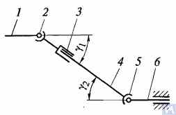
Figure 1. Diagram of a universal joint drive: 1, 4, 6 — driveshafts; 2, 5 — universal joints; 3 — compensating connection; u1, u2 — angles between shafts
โดยทั่วไป ข้อต่อแบบยูนิเวอร์แซลประกอบด้วยข้อต่อแบบยูนิเวอร์แซล 2 และ 5 เพลาขับ 1, 4 และ 6 และข้อต่อชดเชย 3 บางครั้งเพลาขับจะติดตั้งบนตัวรองรับกลางที่ติดอยู่กับโครงขวางของรถยนต์ ข้อต่อแบบยูนิเวอร์แซลทำหน้าที่ส่งผ่านแรงบิดระหว่างเพลาที่มีแกนตัดกันเป็นมุม ข้อต่อแบบยูนิเวอร์แซลแบ่งออกเป็นแบบความเร็วไม่สม่ำเสมอและแบบความเร็วคงที่ ข้อต่อแบบความเร็วไม่สม่ำเสมอยังแบ่งย่อยได้อีกเป็นแบบยืดหยุ่นและแบบแข็ง ข้อต่อความเร็วคงที่อาจเป็นแบบลูกบอลที่มีร่องแบ่ง แบบลูกบอลที่มีคันโยกแบ่ง และแบบลูกเบี้ยว โดยทั่วไปจะติดตั้งในระบบขับเคลื่อนของล้อนำที่ควบคุมได้ ซึ่งมุมระหว่างเพลาทั้งสองสามารถสูงถึง 45° และจุดศูนย์กลางของข้อต่อแบบยูนิเวอร์แซลต้องตรงกับจุดตัดของแกนหมุนของล้อและแกนหมุน
ข้อต่อยูนิเวอร์แซลแบบยืดหยุ่นส่งผ่านแรงบิดระหว่างเพลาที่มีแกนตัดกันที่มุม 2...3° เนื่องจากการเสียรูปยืดหยุ่นของชิ้นส่วนเชื่อมต่อ ข้อต่อความเร็วแบบแข็งและไม่สม่ำเสมอส่งผ่านแรงบิดจากเพลาหนึ่งไปยังอีกเพลาหนึ่งผ่านการเชื่อมต่อที่เคลื่อนที่ได้ของชิ้นส่วนแข็ง ข้อต่อนี้ประกอบด้วยแอกสองอัน คือ 3 และ 5 เข้าไปในรูทรงกระบอกซึ่งมีปลาย A, B, V และ G ของชิ้นส่วนเชื่อมต่อ ซึ่งก็คือกากบาท 4 ติดตั้งอยู่บนตลับลูกปืน แอกทั้งสองเชื่อมต่ออย่างแน่นหนากับเพลา 1 และ 2 แอก 5 สามารถหมุนรอบแกน BG ของกากบาท และในขณะเดียวกัน กากบาทยังหมุนรอบแกน AV ร่วมกับแอก ทำให้สามารถส่งผ่านการหมุนจากเพลาหนึ่งไปยังอีกเพลาหนึ่งด้วยมุมที่เปลี่ยนแปลงระหว่างกัน
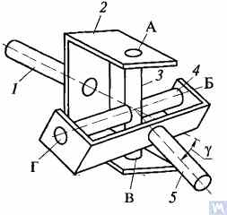
Figure 2. Diagram of a rigid non-uniform velocity universal joint
If shaft 7 rotates around its axis by an angle α, then shaft 2 will rotate by an angle β over the same period. The relationship between the rotation angles of shafts 7 and 2 is determined by the expression tanα = tanβ * cosγโดยที่ γ คือมุมที่แกนของเพลาถูกจัดวาง สมการนี้บ่งชี้ว่ามุม β บางครั้งน้อยกว่า เท่ากับ หรือมากกว่ามุม α ความเท่ากันของมุมเหล่านี้เกิดขึ้นทุกๆ 90° ของการหมุนของเพลา 7 ดังนั้น เมื่อเพลา 1 หมุนสม่ำเสมอ ความเร็วเชิงมุมของเพลา 2 จะไม่สม่ำเสมอและแปรผันตามกฎไซน์ ความไม่สม่ำเสมอของการหมุนของเพลา 2 จะยิ่งมีนัยสำคัญมากขึ้นเมื่อมุม γ ระหว่างแกนเพลาเพิ่มขึ้น
If the non-uniform rotation of shaft 2 is transmitted to the shafts of the units, additional pulsating loads will occur in the transmission, increasing with the angle γ. To prevent the non-uniform rotation of shaft 2 from being transmitted to the unit shafts, two universal joints are used in the universal joint drive. They are installed so that the angles γ1 and γ2 are equal; the forks of the universal joints, fixed on the non-uniformly rotating shaft 4, should be positioned in the same plane.
การออกแบบชิ้นส่วนหลักของชุดขับเคลื่อนข้อต่ออเนกประสงค์แสดงในรูปที่ 3 ข้อต่ออเนกประสงค์ความเร็วไม่สม่ำเสมอประกอบด้วยแอกสองอัน (1) เชื่อมต่อกันด้วยกากบาท (3) แอกอันหนึ่งบางครั้งมีหน้าแปลน ในขณะที่อีกอันเชื่อมติดกับท่อเพลาขับหรือมีปลายแบบสลัก (6) (หรือปลอก) สำหรับเชื่อมต่อกับเพลาขับ แกนยึดของแอกติดตั้งอยู่ในตาของแอกทั้งสองบนตลับลูกปืนเข็ม (7) ตลับลูกปืนแต่ละตัวบรรจุอยู่ในเคส (2) และยึดไว้ในตาของแอกด้วยฝาครอบ ซึ่งยึดติดกับแอกด้วยสลักเกลียวสองตัวที่ล็อกด้วยแถบบนแหวนรอง ในบางกรณี ตลับลูกปืนจะถูกยึดเข้ากับแอกด้วยแหวนสแนป เพื่อรักษาการหล่อลื่นในตลับลูกปืนและป้องกันน้ำและสิ่งสกปรก มีซีลยางที่ขันแน่นเองได้ โพรงด้านในของแอกถูกเติมด้วยจาระบีผ่านอุปกรณ์อัดจาระบี ซึ่งเข้าถึงตลับลูกปืน โดยทั่วไปแล้ว กากบาทจะมีวาล์วนิรภัยเพื่อป้องกันซีลจากความเสียหายอันเนื่องมาจากแรงดันของจารบีที่ถูกสูบเข้าไปในกากบาท ข้อต่อแบบสลัก (6) ได้รับการหล่อลื่นโดยใช้อุปกรณ์จารบี (5)
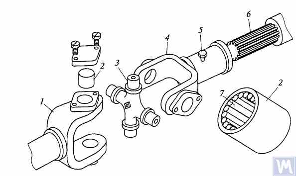
Figure 3. Details of a rigid non-uniform velocity universal joint
มุมสูงสุดระหว่างแกนของเพลาที่เชื่อมต่อด้วยข้อต่อยูนิเวอร์แซลแบบแข็งที่มีความเร็วไม่สม่ำเสมอโดยปกติแล้วจะไม่เกิน 20° เนื่องจากประสิทธิภาพจะลดลงอย่างมากที่มุมที่กว้าง หากมุมระหว่างแกนเพลาเปลี่ยนแปลงภายใน 0...2% แกนของเพลาไขว้จะถูกลูกปืนเข็มทำให้เสียรูป ซึ่งทำให้ข้อต่อยูนิเวอร์แซลเสียหายอย่างรวดเร็ว
ในระบบส่งกำลังของยานยนต์ติดตามความเร็วสูง มักใช้ข้อต่ออเนกประสงค์แบบมีข้อต่อเฟือง ซึ่งช่วยให้สามารถส่งแรงบิดระหว่างเพลาที่มีแกนตัดกันเป็นมุมได้ถึง 1.5...2°
Driveshafts are typically made tubular, using special steel seamless or welded tubes. The yokes of the universal joints, splined sleeves, or tips are welded to the tubes. To reduce the transverse loads acting on the driveshaft, dynamic balancing is performed with the universal joints assembled. Imbalance is corrected by welding balancing plates to the driveshaft or sometimes by installing balancing plates under the bearing caps of the universal joints. The relative position of the splined connection parts after assembly and balancing of the universal joint drive at the factory is usually marked with special labels.
The compensating connection of the universal joint drive is usually made in the form of a splined connection, allowing axial movement of the universal joint drive parts. It consists of a splined tip that fits into the splined sleeve of the universal joint drive. Lubrication is introduced into the splined connection through a grease fitting or applied during assembly and replaced after prolonged use of the vehicle. A seal and a cover are typically installed to prevent grease leakage and contamination.
For long driveshafts, intermediate supports are usually used in universal joint drives. An intermediate support typically consists of a bracket bolted to the vehicle frame cross member, in which a ball bearing is mounted in a rubber elastic ring. The bearing is sealed on both sides with caps and has a lubrication device. The elastic rubber ring helps to compensate for assembly inaccuracies and bearing misalignment that may occur due to frame deformations.
A universal joint with needle bearings (Figure 4a) consists of yokes, a cross, needle bearings, and seals. The cups with needle bearings are fitted onto the trunnions of the cross and sealed with seals. The cups are secured in the yokes with snap rings or caps fastened with screws. Universal joints are lubricated through a grease fitting via internal drillings in the cross. A safety valve is used to eliminate excess oil pressure in the joint. During uniform rotation of the driving yoke, the driven yoke rotates non-uniformly: it advances and lags behind the driving yoke twice per revolution. To eliminate non-uniform rotation and reduce inertial loads, two universal joints are used.
In the drive to the front driving wheels, constant velocity universal joints are installed. The constant velocity joint drive of GAZ-66 and ZIL-131 vehicles consists of yokes 2, 5 (Figure 4b), four balls 7, and a central ball 8. The driving yoke 2 is integral with the inner axle shaft, while the driven yoke is forged together with the outer axle shaft, at the end of which the wheel hub is fixed. The driving moment from yoke 2 to yoke 5 is transmitted through balls 7, which move along circular grooves in the yokes. The central ball 8 serves to center the yokes and is held in place by studs 3, 4. The rotation frequency of yokes 2, 5 is the same due to the symmetry of the mechanism relative to the yokes. The change in shaft length is ensured by the free splined connections of the yokes with the shaft.
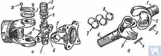
Figure 4. Universal Joints: a — universal joint: 1 — cap; 2 — cup; 3 — needle bearing; 4 — seal; 5, 9 — yokes; 6 — safety valve; 7 — cross; 8 — grease fitting; 10 — screw; b — constant velocity universal joint: 1 — inner axle shaft; 2 — driving yoke; 3, 4 — studs; 5 — driven yoke; 6 — outer axle shaft; 7 — balls; 8 — central ball
2. Universal Joint Drive Malfunctions
Universal joint drive malfunctions typically manifest as sharp knocks in the universal joints that occur when the vehicle is moving, especially during shifts between gears and sudden increases in the engine crankshaft speed (for example, when transitioning from engine braking to acceleration). A sign of universal joint malfunction can be its heating to a high temperature (over 100°C). This happens due to significant wear of the bushings and trunnions of the universal joint, needle bearings, crosses, and splined connections, resulting in misalignment of the universal joint and significant impact axial loads on the needle bearings. Damage to the cork seals of the universal joint cross leads to rapid wear of the trunnion and its bearing.
During maintenance, the universal joint drive is checked by sharply rotating the driveshaft by hand in both directions. The degree of free rotation of the shaft determines the wear of the universal joints and splined connections. Every 8-10 thousand kilometers, the condition of the bolted connections of the driven shaft flanges of the gearbox and the drive shaft of the main transmission gear with the flanges of the end universal joints and the fastening of the intermediate support of the driveshaft are checked. The condition of the rubber boots on the splined connections and the cork seals of the universal joint cross is also checked. All fastening bolts must be tightened fully (tightening torque 8-10 kgf·m).
Needle bearings of the universal joints are lubricated with liquid oil used for transmission units; splined connections in most vehicles are lubricated with greases (US-1, US-2, 1-13, etc.); the use of grease for lubricating needle bearings is strictly prohibited. In some vehicles, splined connections are lubricated with transmission oil. The intermediate support bearing, mounted in a rubber sleeve, practically does not require lubrication, as it is lubricated during assembly at the factory. The support bearing of the ZIL-130 vehicle is lubricated with grease through a pressure fitting during regular maintenance (every 1100-1700 km).
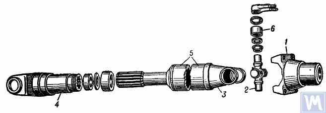
Figure 5. Universal joint drive: 1 — flange for securing the driveshaft; 2 — universal joint cross; 3 — universal joint yoke; 4 — sliding yoke; 5 — driveshaft tube; 6 — needle roller bearing with closed end
The universal joint drive consists of two universal joints with needle bearings, connected by a hollow shaft, and a sliding yoke with involute splines. To ensure reliable protection from dirt and provide good lubrication of the splined connection, the sliding yoke (6), connected to the secondary shaft (2) of the gearbox, is placed in an extension (1) attached to the gearbox housing. Additionally, this location of the splined connection (outside the zone between the joints) significantly increases the stiffness of the universal joint drive and reduces the likelihood of shaft vibrations when the sliding splined connection wears out.
เพลาขับทำจากท่อเชื่อมไฟฟ้าผนังบาง (8) ซึ่งมีแอก (9) ที่เหมือนกันสองอันถูกกดให้แน่นที่ปลายแต่ละด้าน แล้วจึงเชื่อมด้วยการเชื่อมอาร์ก ตัวเรือนลูกปืนเข็ม (18) ของกากบาท (25) ถูกกดให้แน่นเข้ากับตาของแอก (9) และยึดด้วยแหวนยึดสปริง (20) ตลับลูกปืนข้อต่ออเนกประสงค์แต่ละตัวมีเข็ม 22 อัน (21) ฝาครอบแบบปั๊ม (24) ถูกกดให้แน่นเข้ากับแกนยึดที่ยื่นออกมาของกากบาท ซึ่งติดตั้งแหวนไม้ก๊อก (23) ไว้ ตลับลูกปืนได้รับการหล่อลื่นโดยใช้อุปกรณ์อัดจาระบีแบบเหลี่ยม (17) ที่ขันเข้ากับรูเกลียวตรงกลางของกากบาท ซึ่งเชื่อมต่อกับช่องทะลุในแกนยึดของกากบาท อีกด้านหนึ่งของข้อต่อแบบยูนิเวอร์แซลครอส มีวาล์วนิรภัย (16) อยู่ตรงกลาง ออกแบบมาเพื่อระบายจาระบีส่วนเกินขณะเติมข้อต่อและลูกปืน และป้องกันแรงดันสะสมภายในข้อต่อขณะทำงาน (วาล์วจะทำงานที่แรงดันประมาณ 3.5 กก./ตร.ซม.) ความจำเป็นในการมีวาล์วนิรภัยนี้เนื่องจากแรงดันที่เพิ่มขึ้นมากเกินไปภายในข้อต่ออาจทำให้ซีลคอร์กเสียหาย (เกิดการอัดรีด) ได้
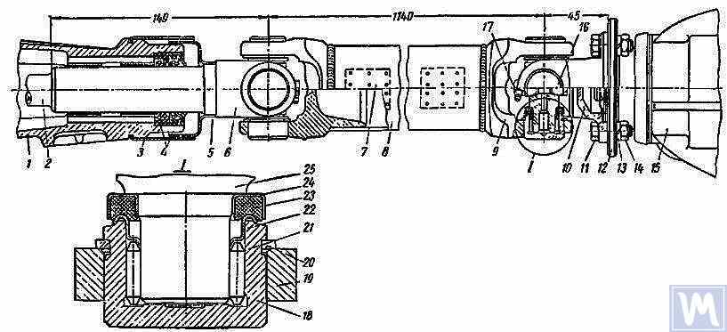
Figure 6. Driveshaft Assembly: 1 — gearbox extension; 2 — secondary shaft of the gearbox; 3 and 5 — dirt deflectors; 4 — rubber seals; 6 — sliding yoke; 7 — balancing plate; 8 — driveshaft tube; 9 — yoke; 10 — flange yoke; 11 — bolt; 12 — flange of the rear axle drive gear; 13 — spring washer; 14 — nut; 15 — rear axle; 16 — safety valve; 17 — angular grease fitting; 18 — needle bearing; 19 — yoke eye; 20 — spring retaining ring; 21 — needle; 22 — washer with toroidal end; 23 — cork ring; 24 — stamped cap; 25 — cross
เพลาขับที่ประกอบเข้ากับข้อต่ออเนกประสงค์ทั้งสองข้าง ได้รับการปรับสมดุลแบบไดนามิกอย่างระมัดระวังที่ปลายทั้งสองด้านโดยการเชื่อมแผ่นปรับสมดุล (7) เข้ากับท่อ ดังนั้น เมื่อถอดประกอบเพลา จะต้องทำเครื่องหมายชิ้นส่วนทั้งหมดอย่างระมัดระวังเพื่อให้สามารถประกอบกลับเข้าที่เดิมได้ การไม่ปฏิบัติตามคำแนะนำนี้จะรบกวนสมดุลของเพลา ทำให้เกิดการสั่นสะเทือนซึ่งอาจทำให้ระบบส่งกำลังและตัวถังรถเสียหายได้ หากชิ้นส่วนแต่ละชิ้นสึกหรอ โดยเฉพาะอย่างยิ่งหากท่อโค้งงอเนื่องจากแรงกระแทก และไม่สามารถปรับสมดุลเพลาแบบไดนามิกได้หลังจากประกอบแล้ว จำเป็นต้องเปลี่ยนเพลาทั้งหมด
Possible Driveshaft Malfunctions, Their Causes, and Solutions
| Cause of Malfunction | Solution |
|---|---|
| Driveshaft Vibration | |
| 1. Shaft bending due to an obstacle | 1. Straighten and dynamically balance the assembled shaft or replace the assembled shaft |
| 2. Bearing and cross wear | 2. Replace bearings and crosses and dynamically balance the assembled shaft |
| 3. Wear of extension bushings and sliding yoke | 3. Replace the extension and sliding yoke and dynamically balance the assembled shaft |
| Knocks When Starting and Coasting | |
| 1. Wear of sliding yoke splines or secondary gearbox shaft | 1. Replace worn parts. When replacing the sliding yoke, dynamically balance the assembled shaft |
| 2. Loose bolts securing the flange yoke to the rear axle drive gear flange | 2. Tighten bolts |
| Oil Throwing from Universal Joint Seals | |
| Wear of cork rings in universal joint seals | Replace cork rings, maintaining the relative position of all driveshaft parts during reassembly. If there is wear on crosses and bearings, replace the bearings and crosses and dynamically balance the assembled shaft |
3. Driveshaft Balancing
After repairing and assembling the driveshaft, it is dynamically balanced on a machine. One design of a balancing machine is shown in Figure 7. The machine consists of a plate (18), a pendulum frame (8) mounted on four vertical elastic rods (3), ensuring its oscillation in the horizontal plane. A bracket and front headstock (9), secured on a bracket (4), are mounted on the longitudinal tubes of the pendulum frame (8). The rear headstock (6) is on a movable traverse (5), allowing dynamic balancing of driveshafts of different lengths. The headstock spindles are mounted on precision ball bearings. The spindle of the front headstock (9) is driven by an electric motor installed in the machine base, through a V-belt drive and an intermediate shaft, on which a limb (10) (graduated disk) is mounted. Additionally, two stands (15) with retractable locking pins (17) are installed on the machine plate (18), ensuring the fixation of the front and rear ends of the pendulum frame depending on the balancing of the front or rear end of the driveshaft.
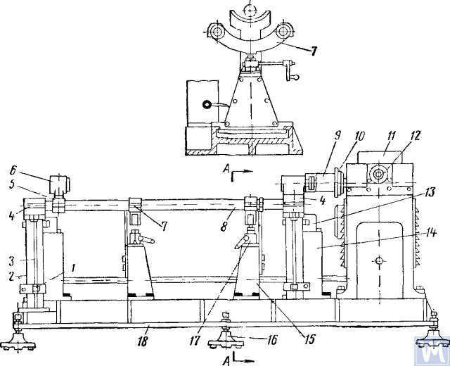
Figure 7. Dynamic Balancing Machine for Driveshafts
1—clamp; 2—dampers; 3—elastic rod; 4—bracket; 5—movable traverse; 6—rear headstock; 7—crossbar; 8—pendulum frame; 9—front driving headstock; 10—limb-disk; 11—millivoltmeter; 12—limb of the commutator-rectifier shaft; 13—magnetoelectric sensor; 14—fixed stand; 15—fixator stand; 16—support; 17—fixator; 18—support plate
The fixed stands (14) are mounted at the rear of the machine plate, and magnetoelectric sensors (13) are installed on them, with rods connected to the ends of the pendulum frame. To prevent resonance vibrations of the frame, dampers (2) filled with oil are installed under the brackets (4).
ในระหว่างการปรับสมดุลแบบไดนามิก ชุดเพลาขับพร้อมแอกเลื่อนจะถูกติดตั้งและยึดเข้ากับเครื่องจักร ปลายด้านหนึ่งของเพลาขับเชื่อมต่อกับหน้าแปลนของหัวจับขับเคลื่อนด้านหน้าด้วยแอกแบบหน้าแปลน และปลายอีกด้านหนึ่งเชื่อมต่อกับคอรองรับของแอกเลื่อนเข้ากับปลอกแบบสลักของหัวจับขับเคลื่อนด้านหลัง จากนั้นตรวจสอบความง่ายในการหมุนของเพลาขับ และตรึงปลายด้านหนึ่งของโครงลูกตุ้มของเครื่องจักรด้วยอุปกรณ์ตรึง หลังจากสตาร์ทเครื่องจักร ขาของเครื่องแปลงกระแสไฟฟ้าจะหมุนทวนเข็มนาฬิกา ทำให้เข็มมิลลิโวลต์มิเตอร์อ่านค่าได้สูงสุด ค่ามิลลิโวลต์มิเตอร์จะสอดคล้องกับขนาดของความไม่สมดุล สเกลมิลลิโวลต์มิเตอร์มีหน่วยเป็นกรัม-เซนติเมตร หรือกรัมของน้ำหนักถ่วง เมื่อหมุนขาของเครื่องแปลงกระแสไฟฟ้าทวนเข็มนาฬิกาต่อไป ค่ามิลลิโวลต์มิเตอร์จะปรับเป็นศูนย์ และเครื่องจักรจะหยุดทำงาน จากการอ่านค่าของขาเรียงกระแส (Rectifier limb) จะมีการตรวจวัดการเคลื่อนตัวเชิงมุม (มุมของความไม่สมดุล) และค่านี้จะถูกตั้งค่าบนขากลางของเพลาโดยการหมุนเพลาขับด้วยมือ ตำแหน่งการเชื่อมของแผ่นถ่วงดุลจะอยู่ที่ด้านบนของเพลาขับ และส่วนที่มีน้ำหนักจะอยู่ด้านล่างในระนาบการแก้ไข จากนั้นจึงติดตั้งแผ่นถ่วงดุลและผูกด้วยลวดเส้นเล็กที่ระยะห่าง 10 มม. จากรอยเชื่อม สตาร์ทเครื่องและตรวจสอบความสมดุลของปลายเพลาขับกับแผ่น ความไม่สมดุลไม่ควรเกิน 70 กรัม/ซม. จากนั้น ปล่อยปลายด้านหนึ่งออกและยึดปลายอีกด้านหนึ่งของโครงลูกตุ้มด้วยขาตั้งตรึง จากนั้นทำการปรับสมดุลแบบไดนามิกของปลายอีกด้านหนึ่งของเพลาขับตามลำดับขั้นตอนทางเทคโนโลยีที่อธิบายไว้ข้างต้น
Driveshafts have some balancing features. For most parts, the base for dynamic balancing is the support necks (e.g., rotors of electric motors, turbines, spindles, crankshafts, etc.), but for driveshafts, it is the flanges. During assembly, there are unavoidable gaps in different connections leading to imbalance. If the minimum imbalance cannot be achieved during balancing, the shaft is rejected. The accuracy of balancing is influenced by the following factors:
- Gap in the connection between the landing belt of the driveshaft flange and the inner hole of the clamping flange of the left and right support headstocks;
- Radial and end runout of the base surfaces of the flange;
- ช่องว่างในบานพับและจุดเชื่อมต่อแบบสลัก การมีจาระบีอยู่ในช่องว่างของจุดเชื่อมต่อแบบสลักอาจทำให้เกิดความไม่สมดุลแบบ “ลอย” หากจาระบีไม่สามารถรักษาสมดุลได้อย่างแม่นยำตามที่ต้องการ เพลาขับจะสมดุลโดยไม่ต้องใช้จาระบี
Some imbalances may be completely uncorrectable. If increased friction is observed in the universal joints of the driveshaft, the mutual influence of the correction planes increases. This leads to a decrease in the performance and accuracy of balancing.
ไทย ตาม OST 37.001.053-74 ได้มีการกำหนดมาตรฐานความไม่สมดุลดังต่อไปนี้: เพลาขับที่มีข้อต่อสองข้อ (สองจุดรองรับ) จะได้รับการปรับสมดุลแบบไดนามิก และมีสามข้อ (สามจุดรองรับ) ซึ่งประกอบเข้ากับจุดรองรับกลาง; หน้าแปลน (แอก) ของเพลาขับและข้อต่อที่มีน้ำหนักมากกว่า 5 กก. จะได้รับการปรับสมดุลแบบคงที่ก่อนที่จะประกอบเพลาหรือข้อต่อ; มาตรฐานความไม่สมดุลที่เหลือสำหรับเพลาขับที่ปลายแต่ละด้านหรือที่จุดรองรับกลางของเพลาขับสามจุดจะได้รับการประเมินโดยความไม่สมดุลที่เฉพาะเจาะจง
ค่ามาตรฐานความไม่สมดุลตกค้างสูงสุดที่อนุญาตได้ที่ปลายเพลาแต่ละด้านหรือที่จุดรองรับกลาง รวมถึงเพลาขับสามข้อต่อในตำแหน่งใดๆ บนแท่นถ่วงน้ำหนัก ไม่ควรเกิน: สำหรับระบบส่งกำลังของรถยนต์นั่งส่วนบุคคลและรถบรรทุกขนาดเล็ก (ไม่เกิน 1 ตัน) และรถโดยสารขนาดเล็กมาก – 6 กรัม-ซม./กก. สำหรับส่วนที่เหลือ – 10 กรัม-ซม./กก. ควรตรวจสอบค่ามาตรฐานความไม่สมดุลตกค้างสูงสุดของเพลาขับหรือเพลาขับสามข้อต่อบนแท่นถ่วงน้ำหนักที่ความถี่การหมุนที่สอดคล้องกับความถี่ในระบบส่งกำลังที่ความเร็วสูงสุดของรถ
สำหรับเพลาขับและเพลาขับสามข้อต่อของรถบรรทุกที่มีน้ำหนักบรรทุกตั้งแต่ 4 ตันขึ้นไป รถโดยสารขนาดเล็กและขนาดใหญ่ อนุญาตให้ลดความถี่การหมุนบนแท่นถ่วงล้อลงเหลือ 70% ของความถี่การหมุนของเพลาส่งกำลังที่ความเร็วสูงสุดของรถ ตาม OST 37.001.053-74 ความถี่การหมุนของเพลาขับเพื่อถ่วงล้อควรเท่ากับ:
nb = (0.7 ... 1.0) นr,
where nb – ความถี่การหมุนสมดุล (ควรสอดคล้องกับข้อมูลทางเทคนิคหลักของบูธ n=3000 นาที-1; nr – ความถี่รอบการทำงานสูงสุด, นาที-1.
In practice, due to the gap in the joints and splined connections, the driveshaft cannot be balanced at the recommended rotation frequency. In this case, another rotation frequency is chosen, at which it balances.
4. Modern Balancing Machines for Driveshafts
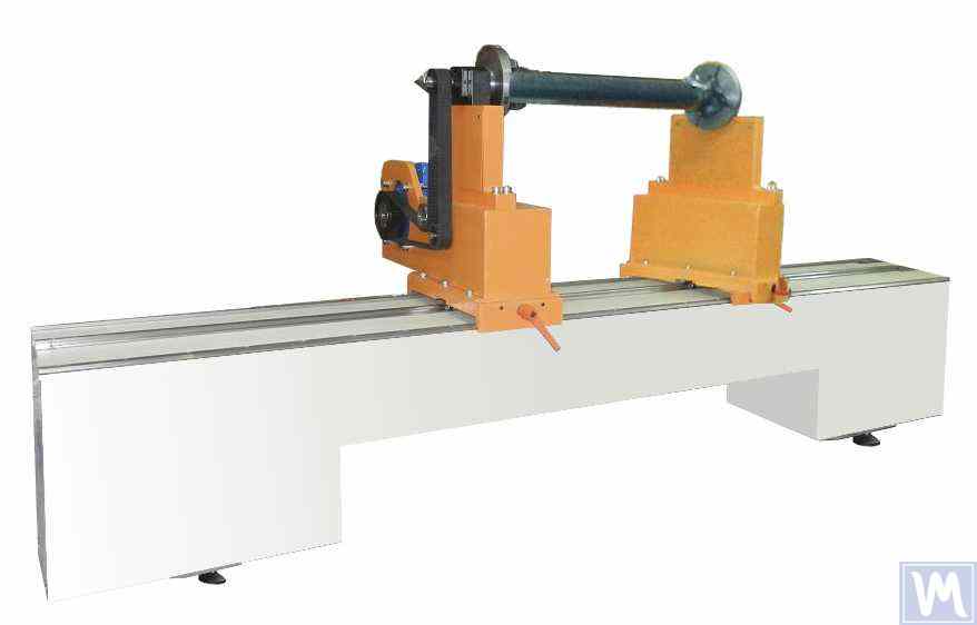
Figure 8. Balancing Machine for Driveshafts up to 2 Meters Long, Weighing up to 500 kg
The model has 2 stands and allows balancing in 2 correction planes.
Balancing Machine for Driveshafts up to 4200 mm Long, Weighing up to 400 kg
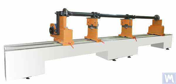
Figure 9. Balancing Machine for Driveshafts up to 4200 mm Long, Weighing up to 400 kg
The model has 4 stands and allows balancing in 4 correction planes simultaneously.
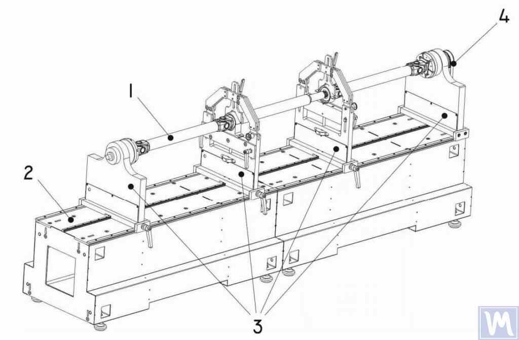
Figure 10. Horizontal Hard Bearing Balancing Machine for Dynamic Balancing of Driveshafts
1 – Balancing item (driveshaft); 2 – Machine base; 3 – Machine supports; 4 – Machine drive; The structural elements of the machine supports are shown in Figure 9.
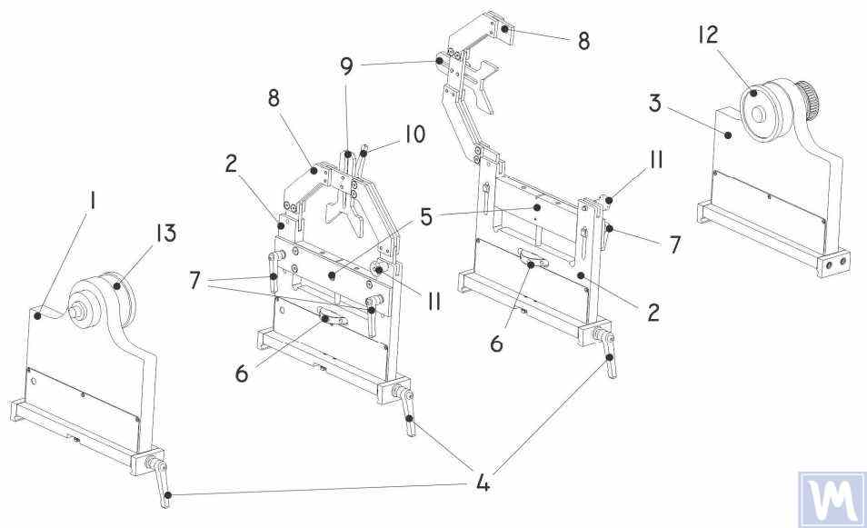
Figure 11. Machine Support Elements for Dynamic Balancing of Driveshafts
1 – Left non-adjustable support; 2 – Intermediate adjustable support (2 pcs.); 3 – Right non-adjustable fixed support; 4 – Support frame lock handle; 5 – Movable support platform; 6 – Support vertical adjustment nut; 7 – Vertical position lock handles; 8 – Support clamping bracket; 9 – Intermediate bearing movable clamp; 10 – Clamp lock handle; 11 – Clamping bracket lock; 12 – Drive (leading) spindle for item installation; 13 – Driven spindle
5. Preparation for Driveshaft Balancing
Below, we will consider the setup of the machine supports and the installation of the balancing item (four-support driveshaft) on the machine supports.
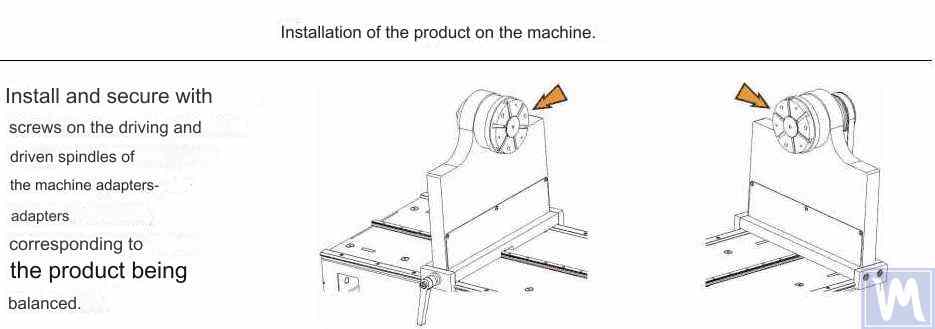
Figure 12. Installation of Transitional Flanges on the Spindles of the Balancing Machine
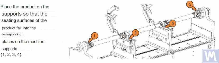
Figure 13. Installation of the Driveshaft on the Supports of the Balancing Machine
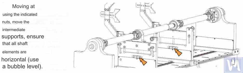
Figure 14. Leveling the Driveshaft Horizontally on the Supports of the Balancing Machine Using a Bubble Level
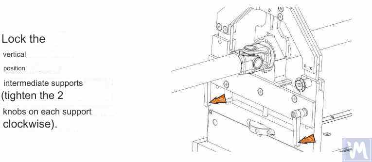
Figure 15. Fixing the Intermediate Supports of the Balancing Machine to Prevent Vertical Displacement of the Driveshaft
Rotate the item manually for a full turn. Ensure that it rotates freely and without jamming on the supports. After this, the mechanical part of the machine is set up, and the item installation is complete.
6. Driveshaft Balancing Procedure
The process of driveshaft balancing on the balancing machine will be considered using the Balanset-4 measuring system as an example. The Balanset-4 is a portable balancing kit designed for balancing in one, two, three, and four correction planes of rotors, either rotating in their own bearings or mounted on a balancing machine. The device includes up to four vibration sensors, a phase angle sensor, a four-channel measuring unit, and a portable computer.
The entire balancing process, including measurement, processing, and display of information on the magnitude and location of corrective weights, is performed automatically and does not require the user to have additional skills and knowledge beyond the provided instructions. The results of all balancing operations are saved in the Balancing Archive and can be printed as reports if necessary. In addition to balancing, the Balanset-4 can also be used as a regular vibro-tachometer, allowing measurement on four channels of the root mean square (RMS) value of total vibration, RMS of the rotational component of vibration, and control of rotor rotation frequency.
Furthermore, the device allows displaying graphs of the time function and vibration spectrum by vibration velocity, which can be useful in assessing the technical condition of the balanced machine.
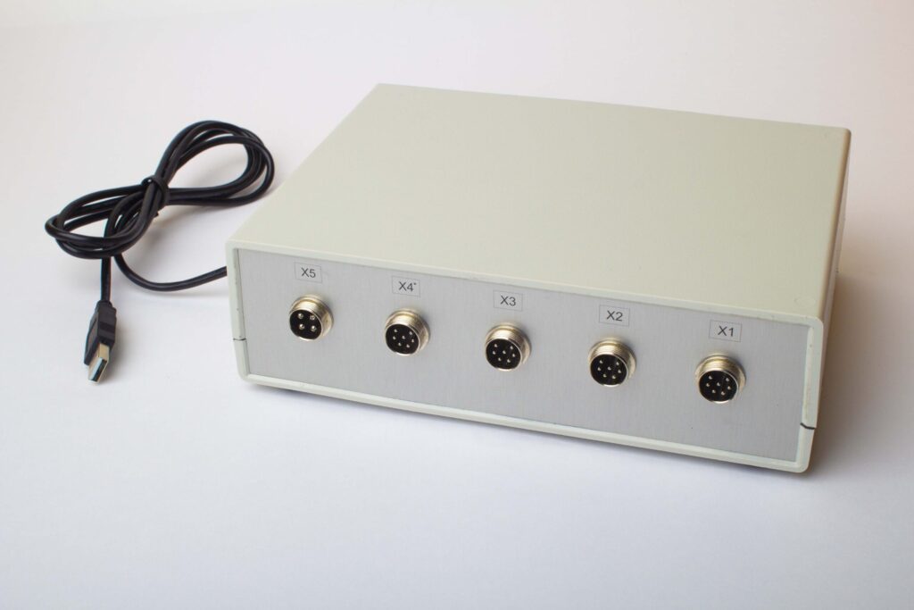
Figure 16. External View of the Balanset-4 Device for Use as a Measuring and Computing System of the Driveshaft Balancing Machine
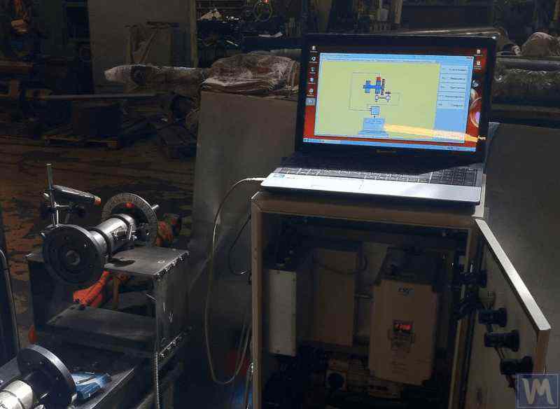
Figure 17. Example of Using the Balanset-4 Device as a Measuring and Computing System of the Driveshaft Balancing Machine
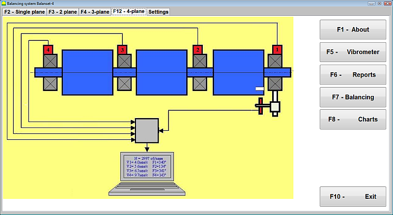
Figure 18. User Interface of the Balanset-4 Device
อุปกรณ์ Balanset-4 สามารถติดตั้งเซ็นเซอร์ได้สองประเภท ได้แก่ เซ็นเซอร์วัดความเร่งการสั่นสะเทือนสำหรับวัดการสั่นสะเทือน (ความเร่งการสั่นสะเทือน) และเซ็นเซอร์วัดแรง เซ็นเซอร์วัดการสั่นสะเทือนใช้สำหรับการทำงานของเครื่องปรับสมดุลแบบหลังการสั่นพ้อง ในขณะที่เซ็นเซอร์วัดแรงใช้สำหรับเครื่องปรับสมดุลแบบก่อนการสั่นพ้อง
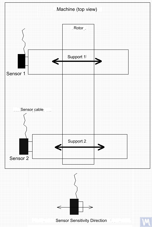
Figure 19. Installation of Balanset-4 Vibration Sensors on the Supports of the Balancing Machine
ทิศทางของแกนความไวของเซ็นเซอร์ควรสอดคล้องกับทิศทางการเคลื่อนที่ของแรงสั่นสะเทือนของตัวรองรับ ซึ่งในกรณีนี้คือแนวนอน สำหรับข้อมูลเพิ่มเติมเกี่ยวกับการติดตั้งเซ็นเซอร์ โปรดดูหัวข้อการปรับสมดุลโรเตอร์ในสภาวะการทำงาน การติดตั้งเซ็นเซอร์แรงขึ้นอยู่กับคุณสมบัติการออกแบบของเครื่องจักร
- Install vibration sensors 1, 2, 3, 4 on the supports of the balancing machine.
- Connect the vibration sensors to connectors X1, X2, X3, X4.
- Install the phase angle sensor (laser tachometer) 5 so that the nominal gap between the radial (or end) surface of the balanced rotor and the sensor housing is in the range of 10 to 300 mm.
- Attach a reflective tape mark with a width of at least 10-15 mm to the rotor surface.
- Connect the phase angle sensor to connector X5.
- Connect the measuring unit to the computer’s USB port.
- When using mains power, connect the computer to the power supply unit.
- Connect the power supply unit to a 220 V, 50 Hz network.
- Turn on the computer and select the “BalCom-4” program.
- Press the “F12-four-plane” button (or the F12 function key on the computer keyboard) to select the mode for measuring vibration simultaneously in four planes using vibration sensors 1, 2, 3, 4, connected respectively to inputs X1, X2, X3, and X4 of the measuring unit.
- A mnemonic diagram illustrating the process of measuring vibration simultaneously on four measurement channels (or the process of balancing in four planes) appears on the computer display, as shown in Figure 16.
Before performing balancing, it is recommended to take measurements in the vibrometer mode (F5 button).
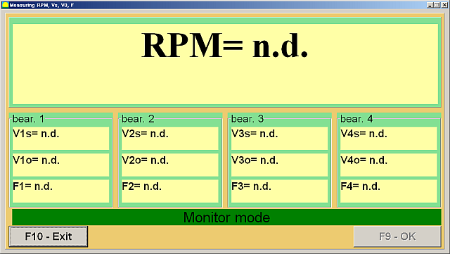
Figure 20. Vibrometer Mode Measurements
หากค่าความสั่นสะเทือนรวม V1 (V2) ใกล้เคียงกับค่าความสั่นสะเทือนของส่วนประกอบการหมุน V1o (V2o) ก็สามารถสันนิษฐานได้ว่าสาเหตุหลักของการสั่นสะเทือนของกลไกเกิดจากความไม่สมดุลของโรเตอร์ หากค่าความสั่นสะเทือนรวม V1 (V2) สูงกว่าค่าความสั่นสะเทือนของส่วนประกอบการหมุน V1o (V2o) อย่างมีนัยสำคัญ ขอแนะนำให้ตรวจสอบกลไก เช่น ตรวจสอบสภาพของตลับลูกปืน ตรวจสอบให้แน่ใจว่าติดตั้งบนฐานรากอย่างแน่นหนา ตรวจสอบว่าโรเตอร์ไม่สัมผัสกับชิ้นส่วนที่หยุดนิ่งระหว่างการหมุน และพิจารณาอิทธิพลของการสั่นสะเทือนจากกลไกอื่นๆ เป็นต้น
การศึกษาฟังก์ชันเวลาและสเปกตรัมการสั่นสะเทือนที่ได้จากโหมด "กราฟ-การวิเคราะห์สเปกตรัม" อาจเป็นประโยชน์ในกรณีนี้
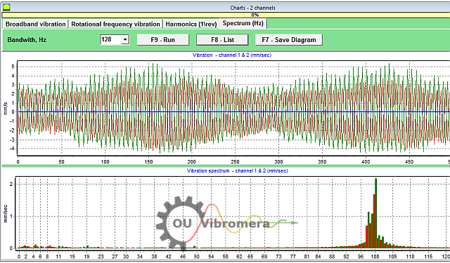
Figure 21. Vibration Time Function and Spectrum Graphs
กราฟแสดงความถี่ที่ระดับการสั่นสะเทือนสูงสุด หากความถี่เหล่านี้แตกต่างจากความถี่การหมุนของโรเตอร์ของกลไกสมดุล จำเป็นต้องระบุแหล่งที่มาขององค์ประกอบการสั่นสะเทือนเหล่านี้และดำเนินมาตรการเพื่อกำจัดออกก่อนทำการสมดุล
It is also important to pay attention to the stability of the readings in vibrometer mode – the amplitude and phase of the vibration should not change by more than 10-15% during measurement. Otherwise, the mechanism might be operating near a resonance region. In this case, the rotor speed should be adjusted.
เมื่อทำการปรับสมดุลแบบสี่ระนาบในโหมด "หลัก" จำเป็นต้องทำการปรับเทียบห้าครั้งและการตรวจสอบเครื่องที่ปรับสมดุลอย่างน้อยหนึ่งครั้ง การวัดการสั่นสะเทือนระหว่างการทำงานเครื่องครั้งแรกโดยไม่มีน้ำหนักทดลองจะดำเนินการในพื้นที่ทำงาน "การปรับสมดุลแบบสี่ระนาบ" การทำงานครั้งต่อๆ ไปจะดำเนินการโดยใช้น้ำหนักทดลองที่ติดตั้งตามลำดับบนเพลาขับในแต่ละระนาบแก้ไข (ในพื้นที่รองรับเครื่องปรับสมดุลแต่ละเครื่อง)
Before each subsequent run, the following steps should be taken:
- หยุดการหมุนของโรเตอร์ของเครื่องจักรที่สมดุล
- Remove the previously installed trial weight.
- Install the trial weight in the next plane.
Figure 23. Four-Plane Balancing Workspace
หลังจากเสร็จสิ้นการวัดแต่ละครั้ง ผลลัพธ์ของความถี่การหมุนของโรเตอร์ (Nob), as well as the RMS values (Vo1, วีo2, วีo3, วีo4) and the phases (F1, F2, F3, F4) ของการสั่นสะเทือนที่ความถี่การหมุนของโรเตอร์สมดุลจะถูกบันทึกไว้ในช่องที่เกี่ยวข้องในหน้าต่างโปรแกรม หลังจากการทำงานครั้งที่ห้า (น้ำหนักในระนาบที่ 4) พื้นที่ทำงาน "Balancing Weights" (ดูรูปที่ 24) จะปรากฏขึ้น โดยแสดงค่าที่คำนวณได้ของมวล (M)1, M2, M3, M4) and the installation angles (f1, f2, f3, f4) of the corrective weights that need to be installed on the rotor in four planes to compensate for its imbalance.
Figure 24. Workspace with Calculated Parameters of Corrective Weights in Four Planes
Attention! หลังจากเสร็จสิ้นกระบวนการวัดในระหว่างรอบที่ 5 ของเครื่องบาลานซ์ จำเป็นต้องหยุดการหมุนของโรเตอร์และนำตุ้มน้ำหนักทดลองที่ติดตั้งไว้ก่อนหน้านี้ออก หลังจากนั้นจึงจะสามารถดำเนินการติดตั้ง (หรือถอด) ตุ้มน้ำหนักแก้ไขบนโรเตอร์ได้
ตำแหน่งเชิงมุมสำหรับการเพิ่ม (หรือลบ) น้ำหนักแก้ไขบนโรเตอร์ในระบบพิกัดเชิงขั้ววัดจากตำแหน่งของการติดตั้งน้ำหนักทดลอง ทิศทางการวัดมุมจะตรงกับทิศทางการหมุนของโรเตอร์ ในกรณีที่มีการปรับสมดุลด้วยใบพัด ใบพัดของโรเตอร์ที่ปรับสมดุลจะถือว่าตรงกับตำแหน่งการติดตั้งน้ำหนักทดลองตามเงื่อนไข ทิศทางการนับหมายเลขของใบพัดที่แสดงบนจอแสดงผลคอมพิวเตอร์จะสอดคล้องกับทิศทางการหมุนของโรเตอร์
ในโปรแกรมเวอร์ชันนี้ ค่าเริ่มต้นของโปรแกรมจะถือว่าน้ำหนักแก้ไขจะถูกเพิ่มเข้าไปในโรเตอร์ ซึ่งจะแสดงด้วยเครื่องหมายที่กำหนดไว้ในช่อง "Add" หากจำเป็นต้องแก้ไขความไม่สมดุลโดยการเอาน้ำหนักออก (เช่น โดยการเจาะ) ให้กำหนดเครื่องหมายในช่อง "Remove" โดยใช้เมาส์ หลังจากนั้น ตำแหน่งเชิงมุมของน้ำหนักแก้ไขจะเปลี่ยนไป 180 องศาโดยอัตโนมัติ
หลังจากติดตั้งตุ้มน้ำหนักแก้ไขบนโรเตอร์ที่ปรับสมดุลแล้ว ให้กดปุ่ม "Exit – F10" (หรือปุ่มฟังก์ชัน F10 บนแป้นพิมพ์คอมพิวเตอร์) เพื่อกลับไปยังพื้นที่ทำงาน "การปรับสมดุลสี่ระนาบ" ก่อนหน้า และตรวจสอบประสิทธิภาพของการปรับสมดุล หลังจากเสร็จสิ้นการตรวจสอบแล้ว ผลลัพธ์ของความถี่การหมุนของโรเตอร์ (N)ob) and the RMS values (Vo1, วีo2, วีo3, วีo4) and phases (F1, F2, F3, F4) ของการสั่นสะเทือนที่ความถี่การหมุนของโรเตอร์ที่ปรับสมดุลจะถูกบันทึกไว้ พร้อมกันนี้ พื้นที่ทำงาน "Balancing Weights" (ดูรูปที่ 21) จะปรากฏขึ้นเหนือพื้นที่ทำงาน "Four-Plane Balancing" โดยแสดงพารามิเตอร์ที่คำนวณได้ของน้ำหนักแก้ไขเพิ่มเติมที่ต้องติดตั้ง (หรือถอดออก) บนโรเตอร์เพื่อชดเชยความไม่สมดุลที่เหลืออยู่ นอกจากนี้ พื้นที่ทำงานนี้ยังแสดงค่าความไม่สมดุลที่เหลืออยู่หลังจากการปรับสมดุล หากค่าการสั่นสะเทือนที่เหลืออยู่และ/หรือความไม่สมดุลที่เหลืออยู่ของโรเตอร์ที่ปรับสมดุลตรงตามข้อกำหนดความคลาดเคลื่อนที่ระบุไว้ในเอกสารทางเทคนิค กระบวนการปรับสมดุลก็จะเสร็จสมบูรณ์ หากไม่เช่นนั้น กระบวนการปรับสมดุลก็สามารถดำเนินต่อไปได้ วิธีนี้ช่วยให้สามารถแก้ไขข้อผิดพลาดที่อาจเกิดขึ้นได้ผ่านการประมาณค่าต่อเนื่องที่อาจเกิดขึ้นเมื่อติดตั้ง (ถอดออก) น้ำหนักแก้ไขบนโรเตอร์ที่ปรับสมดุล
หากกระบวนการปรับสมดุลยังคงดำเนินต่อไป จะต้องติดตั้ง (หรือถอด) น้ำหนักแก้ไขเพิ่มเติมบนโรเตอร์ที่ปรับสมดุลตามพารามิเตอร์ที่ระบุในพื้นที่ทำงาน "การปรับสมดุลน้ำหนัก"
ปุ่ม "ค่าสัมประสิทธิ์ – F8" (หรือปุ่มฟังก์ชัน F8 บนแป้นพิมพ์คอมพิวเตอร์) ใช้เพื่อดูและบันทึกค่าสัมประสิทธิ์การปรับสมดุลโรเตอร์ (ค่าสัมประสิทธิ์อิทธิพลไดนามิก) ที่คำนวณจากผลลัพธ์ของการสอบเทียบ 5 รอบไว้ในหน่วยความจำของคอมพิวเตอร์
7. Recommended Balancing Accuracy Classes for Rigid Rotors
Table 2. Recommended Balancing Accuracy Classes for Rigid Rotors.

Recommended Balancing Accuracy Classes for Rigid Rotors
| Types of Machines (Rotors) | Balancing Accuracy Class | Value eper Ω mm/s |
|---|---|---|
| Drive crankshafts (structurally unbalanced) for large low-speed marine diesel engines (piston speed less than 9 m/s) | G 4000 | 4000 |
| Drive crankshafts (structurally balanced) for large low-speed marine diesel engines (piston speed less than 9 m/s) | G 1600 | 1600 |
| Drive crankshafts (structurally unbalanced) on vibration isolators | G 630 | 630 |
| Drive crankshafts (structurally unbalanced) on rigid supports | G 250 | 250 |
| Reciprocating engines assembled for passenger cars, trucks, and locomotives | G 100 | 100 |
| Automobile parts: wheels, wheel rims, wheelsets, transmissions | ||
| Drive crankshafts (structurally balanced) on vibration isolators | G 40 | 40 |
| Agricultural machines | G 16 | 16 |
| Drive crankshafts (balanced) on rigid supports | ||
| Crushers | ||
| Drive shafts (driveshafts, screw shafts) | ||
| Aircraft gas turbines | G 6.3 | 6.3 |
| Centrifuges (separators, settlers) | ||
| Electric motors and generators (with a shaft height of at least 80 mm) with a maximum nominal rotation speed of up to 950 min-1 | ||
| Electric motors with a shaft height of less than 80 mm | ||
| Fans | ||
| Gear drives | ||
| General-purpose machines | ||
| Metal cutting machines | ||
| Papermaking machines | ||
| Pumps | ||
| Turbochargers | ||
| Water turbines | ||
| Compressors | ||
| Computer-controlled drives | G 2.5 | 2.5 |
| Electric motors and generators (with a shaft height of at least 80 mm) with a maximum nominal rotation speed over 950 min-1 | ||
| Gas and steam turbines | ||
| Metal cutting machine drives | ||
| Textile machines | ||
| Audio and video equipment drives | G 1 | 1 |
| Grinding machine drives | ||
| Spindles and drives of high-precision equipment | G 0.4 | 0.4 |
คำถามที่พบบ่อยเกี่ยวกับการปรับสมดุลเพลาขับ
การถ่วงล้อเพลาขับคืออะไร?
การปรับสมดุลเพลาขับคือกระบวนการแก้ไขความไม่สมดุลของมวลในเพลาขับเพื่อให้หมุนได้อย่างราบรื่นโดยไม่ก่อให้เกิดการสั่นสะเทือน วิธีนี้เกี่ยวข้องกับการวัดตำแหน่งที่เพลามีน้ำหนักมากกว่าด้านใดด้านหนึ่ง จากนั้นจึงเพิ่มหรือลดน้ำหนักเล็กน้อย (เช่น การเชื่อมตุ้มถ่วงน้ำหนัก) เพื่อแก้ไขความไม่สมดุลนั้น เพลาขับที่สมดุลจะทำงานได้สม่ำเสมอ ซึ่งช่วยป้องกันการสั่นสะเทือนและการสึกหรอที่มากเกินไปของชิ้นส่วนรถยนต์
เหตุใดการปรับสมดุลเพลาขับจึงมีความสำคัญ?
เพลาขับที่ไม่สมดุลอาจทำให้เกิดการสั่นสะเทือนอย่างรุนแรง โดยเฉพาะที่ความเร็วบางระดับ และอาจทำให้เกิดเสียงดังกึกก้องขณะเร่งความเร็วหรือเปลี่ยนเกียร์ เมื่อเวลาผ่านไป การสั่นสะเทือนเหล่านี้อาจสร้างความเสียหายให้กับตลับลูกปืน ข้อต่อยูนิเวอร์แซล และส่วนประกอบอื่นๆ ของระบบขับเคลื่อน การปรับสมดุลเพลาขับจะช่วยลดการสั่นสะเทือนเหล่านี้ ช่วยให้การขับขี่ราบรื่นขึ้น ลดแรงกดบนชิ้นส่วน และป้องกันความเสียหายที่มีค่าใช้จ่ายสูงหรือการหยุดทำงาน
อาการทั่วไปของเพลาขับที่ไม่สมดุลมีอะไรบ้าง
อาการทั่วไปของเพลาขับที่ไม่สมดุลหรือชำรุด ได้แก่ รู้สึกถึงแรงสั่นสะเทือนหรือแรงสั่นสะเทือนที่พื้นรถหรือเบาะ โดยเฉพาะเมื่อความเร็วเพิ่มขึ้น คุณอาจได้ยินเสียงเคาะหรือเสียงกระทบกันขณะเปลี่ยนเกียร์ หรือขณะเร่งความเร็วและลดความเร็ว ในบางกรณี ข้อต่อเพลาขับอาจร้อนเกินไปเนื่องจากความไม่สมดุล หากคุณสังเกตเห็นสัญญาณเหล่านี้ แสดงว่าเพลาขับจำเป็นต้องได้รับการถ่วงล้อหรือซ่อมแซม
จะปรับสมดุลเพลาขับอย่างไร?
การปรับสมดุลเพลาขับมักทำโดยใช้เครื่องปรับสมดุลเฉพาะทาง เพลาขับจะถูกติดตั้งและหมุนด้วยความเร็วสูง ขณะที่เซ็นเซอร์ตรวจจับความไม่สมดุล จากนั้นช่างเทคนิคจะติดตุ้มน้ำหนักขนาดเล็กเข้ากับเพลาขับ (หรือนำวัสดุออก) ในตำแหน่งที่กำหนดโดยอ้างอิงจากค่าที่อ่านได้จากเครื่อง กระบวนการนี้จะทำซ้ำจนกว่าเพลาขับจะหมุนโดยไม่มีการสั่นสะเทือนที่รุนแรง ระบบสมัยใหม่เช่น Balanset-4 สามารถแนะนำกระบวนการนี้และคำนวณได้อย่างแม่นยำว่าต้องเพิ่มน้ำหนักเท่าใดและตำแหน่งใดเพื่อการปรับสมดุลอย่างแม่นยำ
Conclusion
สรุปแล้ว การปรับสมดุลเพลาขับให้เหมาะสมถือเป็นสิ่งสำคัญสำหรับความปลอดภัย ประสิทธิภาพ และการประหยัดต้นทุน การตรวจจับและแก้ไขความไม่สมดุลจะช่วยป้องกันการสึกหรอที่ไม่จำเป็นของชิ้นส่วน หลีกเลี่ยงการเสียหายที่ก่อให้เกิดความเสียหาย และรักษาประสิทธิภาพการทำงานของเครื่องจักรให้อยู่ในระดับสูงสุด ระบบปรับสมดุลที่ทันสมัยอย่างอุปกรณ์ Balanset-1 และ Balanset-4 ของเราช่วยให้กระบวนการทำงานมีประสิทธิภาพ ช่วยให้แม้แต่โรงงานขนาดเล็กก็สามารถบรรลุผลลัพธ์ระดับมืออาชีพได้
หากคุณประสบปัญหาเพลาขับสั่นอย่างต่อเนื่องหรือต้องการวิธีแก้ไขที่น่าเชื่อถือ อย่าลังเลที่จะดำเนินการ ปฏิบัติตามขั้นตอนที่ระบุไว้ในคู่มือนี้ หรือปรึกษาผู้เชี่ยวชาญของเราเพื่อขอความช่วยเหลือ ด้วยวิธีการและอุปกรณ์ที่เหมาะสม คุณจะมั่นใจได้ว่าเพลาขับของคุณจะทำงานได้อย่างราบรื่นและเชื่อถือได้ไปอีกหลายปี ติดต่อเรา เพื่อเรียนรู้เพิ่มเติมหรือสำรวจอุปกรณ์ปรับสมดุลเพลาขับที่ดีที่สุดสำหรับความต้องการของคุณ

0 ความคิดเห็น