Meet Vibromera.com — our new international website. Visit Vibromera.com →
DIY Balancing Machines: Build Your Own Professional Rotor Balancer | Vibromera

Balancing Machines with Your Own Hands

作者: Feldman Valery Davidovich
Editor and Translation: Nikolai Andreevich Shelkovenko and ChatGPT

Comprehensive technical guide for building professional-grade balancing machines. Learn about soft bearing vs hard bearing designs, spindle calculations, support systems, and measuring equipment integration.

DIY Balancing Machine Components

Balancing Machine Assembly

便攜式平衡機 & 振動分析儀 Balanset-1A

振動感測器

光學感測器(雷射轉速計)

Balanset-4

磁吸支架 Insize-60-kgf

反光膠帶

動平衡機「Balanset-1A」OEM

1. 簡介

(為何需要撰寫本文件?)

An analysis of the consumption structure of balancing devices manufactured by LLC "Kinematics" (Vibromera) reveals that about 30% of them are purchased for use as stationary measuring and computing systems for balancing machines and/or stands. It is possible to identify two groups of consumers (customers) of our equipment.

第一類包含專門從事動平衡機量產並銷售予外部客戶之企業。這些企業僱用具備深厚知識與豐富經驗之高度專業人員,專精於各類動平衡機之設計、製造與操作。與此類消費者互動時所面臨之挑戰,通常與將我們之測量系統與軟體適配至現有或新開發之機器有關,而不涉及機器結構設計之問題。

第二類消費者則為開發並製造機器(支架)以供自身需求者。此種做法主要係出於獨立製造商降低自身生產成本之願望,在某些情況下成本可降低兩至三倍或更多。此類消費者通常缺乏製造機器之適當經驗,其工作多依賴常識、網路資訊及任何可用之類似產品。

與他們互動會引發許多問題,除動平衡機測量系統之額外資訊外,還涵蓋廣泛議題,包括機器結構設計、基礎安裝方法、驅動裝置選型,以及達成適當動平衡精度等。

Considering the significant interest shown by a large group of our consumers in the issues of independently manufacturing balancing machines, specialists from LLC "Kinematics" (Vibromera) have prepared a compilation with comments and recommendations on the most frequently asked questions.

2. 動平衡機(支架)的類型及其設計特性

A balancing machine is a technological device designed to eliminate the static or dynamic unbalance of rotors for various purposes. It incorporates a mechanism that accelerates the balanced rotor to a specified rotation frequency and a specialized measuring and computing system that determines the masses and placement of corrective weights required to compensate for the rotor's imbalance.

The construction of the mechanical part of the machine typically consists of a bedframe on which support posts (bearings) are installed. These are used to mount the balanced product (rotor) and include a drive intended for rotating the rotor. During the balancing process, which is performed while the product is rotating, the measuring system's sensors (whose type depends on the machine's design) either register vibrations in the bearings or forces at the bearings.

以此方式獲得之資料可用於確定補償不平衡所需之校正配重質量與安裝位置。

目前,兩種動平衡機(支架)設計最為普遍:

  • 軟支撐機 (具彈性支撐);
  • 硬支撐機 (具剛性支撐)。

2.1. 軟支撐機與支架

軟支撐動平衡機(支架)之基本特徵在於其支撐具相對彈性,係基於彈簧懸掛、彈簧安裝滑台、平面或圓柱彈簧支撐等設計。這些支撐之自然頻率至少比安裝於其上之待平衡轉子旋轉頻率低 2 至 3 倍。軟支撐彈性支撐結構設計之經典範例可見於 DB-50 型機器之支撐,其照片如圖 2.1 所示。
P1010213

圖 2.1. DB-50 型動平衡機支撐。

如圖 2.1 所示,可動框架(滑塊)2 透過條形彈簧 3 之懸掛系統連接至支撐之固定柱 1。在安裝於支撐上之轉子不平衡所產生之離心力影響下,滑台(滑塊)2 可相對於固定柱 1 進行水平振盪,此振盪係透過振動感測器進行測量。

此支撐之結構設計可確保滑台振盪之自然頻率較低,約為 1-2 Hz。這使得轉子可在廣泛之旋轉頻率範圍內進行動平衡,起始頻率為 200 RPM。此特性加上製造此類支撐之相對簡便性,使此設計對許多為自身各類需求製造動平衡機之消費者具吸引力。
IMAG0040

Figure 2.2. Soft Bearing Support of the Balancing Machine, Manufactured by "Polymer LTD", Makhachkala

Figure 2.2 shows a photograph of a Soft Bearing balancing machine with supports made from suspension springs, manufactured for in-house needs at "Polymer LTD" in Makhachkala. The machine is designed for balancing rollers used in the production of polymer materials.

圖 2.3 展示了一台具類似滑台條形懸掛系統之動平衡機照片,該機器用於平衡專用工具。

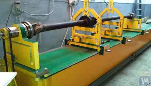
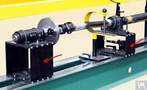
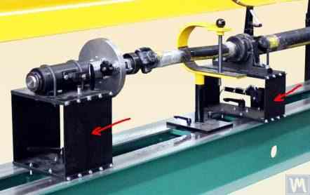
圖 2.4.a 與 2.4.b 展示了一台自製軟支撐動平衡機之照片,該機器用於平衡驅動軸,其支撐亦採用條形懸掛彈簧設計。

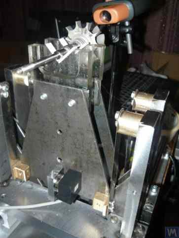
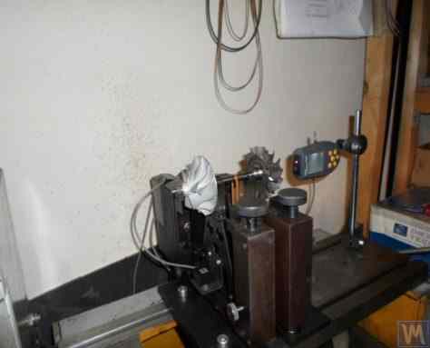
圖 2.5 presents a photograph of a Soft Bearing machine designed for balancing turbochargers, with the supports of its carriages also suspended on strip springs. The machine, made for the private use of A. Shahgunyan (St. Petersburg), is equipped with the "Balanset 1" measuring system.

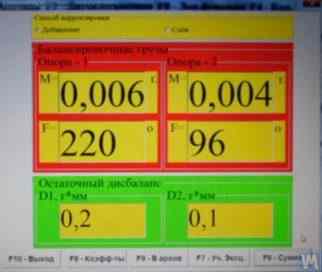
根據製造商(見圖 2.6),該機器具備平衡渦輪機之能力,其殘餘不平衡不超過 0.2 g*mm。
Инстр 1)

圖 2.3. 支撐懸掛於條形彈簧上之工具動平衡軟支撐機

Кар 1

圖 2.4.a. 驅動軸動平衡軟支撐機(機器組裝完成)

Кар2)

圖 2.4.b. 滑台支撐懸掛於條形彈簧上之驅動軸動平衡軟支撐機。 (主軸支撐具條形彈簧懸掛)
SAM_0506

圖 2.5. A. Shahgunyan(聖彼得堡)製造之渦輪增壓器動平衡軟支撐機,支撐懸掛於條形彈簧上
SAM_0504

Figure 2.6. Screen Copy of 'Balanset 1' Measuring System Showing the Results of Turbine Rotor Balancing on A. Shahgunyan's Machine

除上述討論之軟支撐動平衡機支撐經典版本外,其他結構解決方案亦已廣泛應用。

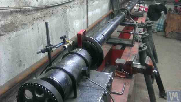
圖 2.7 與 2.8 feature photographs of balancing machines for drive shafts, whose supports are made based on flat (plate) springs. These machines were manufactured for the proprietary needs of the private enterprise "Dergacheva" and LLC "Tatcardan" ("Kinetics-M"), respectively.

Soft Bearing balancing machines with such supports are often reproduced by amateur manufacturers due to their relative simplicity and manufacturability. These prototypes are generally either VBRF series machines from "K. Schenck" or similar domestic production machines.

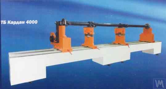
圖 2.7 與 2.8 所示之機器設計用於平衡雙支撐、三支撐與四支撐驅動軸。其結構相似,包含:

  • 焊接床身 1,基於兩根由橫向肋板連接之工字鋼;
  • 固定(前)軸支撐 2;
  • 可移動(後方)主軸支撐座 3;
  • 一個或兩個可移動(中間)支撐座 4。支撐座 2 和 3 內裝有主軸單元 5 和 6,用於在機床上安裝待校正的驅動軸 7。
IMAG1077

Figure 2.7. Soft Bearing Machine for Balancing Drive Shafts by Private Enterprise "Dergacheva" with Supports on Flat (Plate) Springs

image (3)

Figure 2.8. Soft Bearing Machine for Balancing Drive Shafts by LLC "Tatcardan" ("Kinetics-M") with Supports on Flat Springs

所有支撐座上均安裝有感測器 8,用於測量支撐座的橫向振盪。安裝在支撐座 2 上的主導主軸 5 透過皮帶驅動由電動機旋轉。

圖 2.9.a 和 2.9.b 展示了基於扁平彈簧的動平衡機支撐座的照片。
S5007480

S5007481

圖 2.9. 採用扁平彈簧的軟支撐動平衡機支撐座

  • a) 側視圖;
  • b) 前視圖

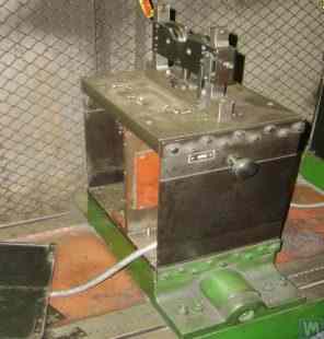
鑑於業餘製造商經常在其設計中使用此類支撐座,詳細檢查其結構特徵是有用的。如圖 2.9.a 所示,該支撐座由三個主要部件組成:

  • 下支撐板 1: 對於前主軸支撐座,該板剛性地固定在導軌上;對於中間支撐座或後主軸支撐座,下板設計為可沿框架導軌移動的滑台。
  • 上支撐板 2, 支撐單元(滾輪支撐座 4、主軸、中間軸承等)安裝在其上。
  • 兩個扁平彈簧 3, 連接下軸承板和上軸承板。

為了防止在運行期間(例如在待校正轉子加速或減速期間)支撐座振動加劇的風險,支撐座可能包含鎖定機構(見圖 2.9.b)。該機構由一個剛性支架 5 組成,該支架可通過連接到支撐座其中一個扁平彈簧的偏心鎖 6 進行接合。當鎖 6 和支架 5 接合時,支撐座被鎖定,消除了加速和減速期間振動加劇的風險。

在設計採用扁平(板狀)彈簧的支撐座時,機械製造商必須評估其自然振盪頻率,這取決於彈簧的剛性和待校正轉子的質量。了解此參數可讓設計人員有意识地選擇轉子的運行旋轉頻率範圍,避免在動平衡過程中支撐座發生共振振盪的危險。

關於計算和實驗確定支撐座以及其他動平衡機組件振盪自然頻率的建議,請參見第 3 節。

如前所述,採用扁平(板狀)彈簧的支撐座設計簡單且易於製造,這吸引了業餘開發人員開發用於各種目的的動平衡機,包括用於校正曲軸、汽車渦輪增壓器轉子等的機器。

As an example, Figures 2.10.a and 2.10.b present a general view sketch of a machine designed for balancing turbocharger rotors. This machine was manufactured and is used for in-house needs at LLC "SuraTurbo" in Penza.

Балансировка турбокомпрессора (1)

2.10.a. 渦輪增壓器轉子動平衡機(側視圖)

Балансировка турбокомпрессора(2)

2.10.b. 渦輪增壓器轉子動平衡機(前支撐座側視圖)

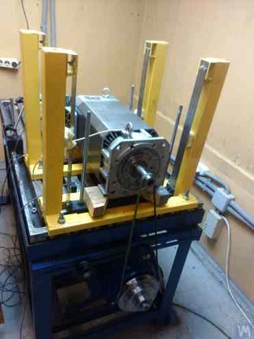
除了前面討論的軟支撐動平衡機外,有時還會創建相對簡單的軟支撐支架。這些支架允許以最小的成本對各種用途的旋轉機構進行高品質的動平衡校正。

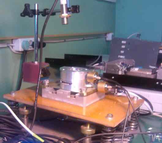
Several such stands are reviewed below, built on the basis of a flat plate (or frame) set on cylindrical compression springs. These springs are usually selected such that the natural frequency of oscillations of the plate with the balanced mechanism installed on it is 2 to 3 times lower than the rotation frequency of this mechanism's rotor during balancing.

圖 2.11 展示了 P. Asharin 為內部生產製造的砂輪動平衡支架的照片。
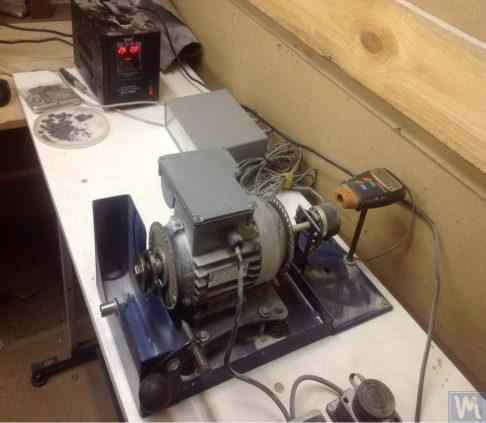
image (1)

圖 2.11. 砂輪動平衡支架

該支架由以下主要部件組成:

  • 板 1,安裝在四個圓柱彈簧 2 上;
  • 電動機 3,其轉子也作為主軸,上面安裝有心軸 4,用於在主軸上安裝和固定砂輪。

A key feature of this stand is the inclusion of a pulse sensor 5 for the rotational angle of the electric motor's rotor, which is used as part of the measuring system of the stand ("Balanset 2C") to determine the angular position for removing the corrective mass from the abrasive wheel.

圖 2.12 shows a photograph of a stand used for balancing vacuum pumps. This stand was developed to order by JSC "Measurement Plant".

Рунёв

Figure 2.12. Stand for Balancing Vacuum Pumps by JSC "Measurement Plant"

該支架的基礎也使用 板 1,安裝在圓柱彈簧 2 上。在板 1 上安裝有真空泵 3,該泵具有自己的電動驅動裝置,能夠在 0 到 60,000 RPM 的範圍內廣泛變速。振動感測器 4 安裝在泵殼上,用於測量不同高度兩個不同部分的振動。

For synchronization of the vibration measurement process with the rotational angle of the pump rotor, a laser phase angle sensor 5 is used on the stand. Despite the seemingly simplistic external construction of such stands, it allows achieving very high-quality balancing of the pump's impeller.

For example, at sub-critical rotational frequencies, the residual imbalance of the pump rotor is below the tolerance of the finest balance quality grade defined in ISO 21940-11 (formerly ISO 1940-1), G0.4 — an in-house bench result equivalent to a notional G0.16, which is tighter than any grade listed in the standard.

在高達 8,000 RPM 的旋轉速度下動平衡期間實現的泵殼殘餘振動不超過 0.01 mm/sec。

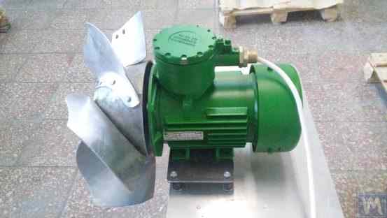
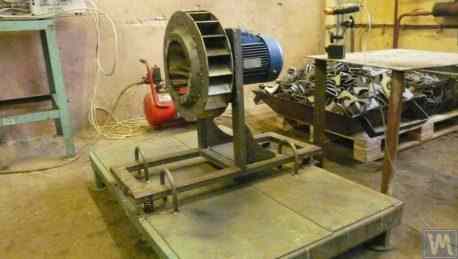
按照上述方案製造的動平衡支架在校正其他機構(如風機)時也同樣有效。圖 2.13 和 2.14 展示了設計用於校正風機的支架示例。
P1030155 (2)

圖 2.13. 風機葉輪動平衡支架

The quality of fan balancing achieved on such stands is quite high. According to specialists from "Atlant-project" LLC, on the stand designed by them based on recommendations from "Kinematics" LLC (see Fig. 2.14), the level of residual vibration achieved when balancing fans was 0.8 mm/sec. This is more than three times better than the tolerance set for fans in category BV5 according to ISO 31350-2007 "Vibration. Industrial fans. Requirements for produced vibration and balance quality."

20161122_100338 (2)

Figure 2.14. Stand for Balancing Fan Impellers of Explosion-Proof Equipment by "Atlant-project" LLC, Podolsk

Similar data obtained at JSC "Lissant Fan Factory" show that such stands, used in the serial production of duct fans, consistently ensured a residual vibration not exceeding 0.1 mm/s.

2.2. 硬支撐機

硬支撐動平衡機與前面討論的軟支撐機在支撐座設計上有所不同。它們的支撐座製成帶有複雜槽口(切口)的剛性板形式。這些支撐座的自然頻率顯著(至少 2-3 倍)高於在機器上校正的轉子的最大旋轉頻率。

硬支承機床比軟支承機床更具多功能性,因為它們通常允許在更廣泛的質量和尺寸特性範圍內對轉子進行高品質動平衡校正。這些機床的另一個重要優勢是,它們能夠在相對較低的轉速下對轉子進行高精度動平衡校正,轉速範圍可低至 200-500 RPM 甚至更低。

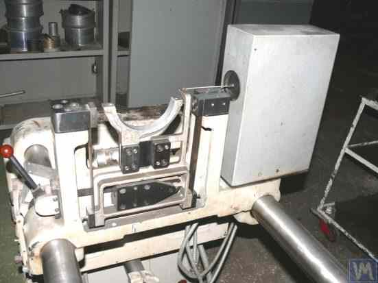
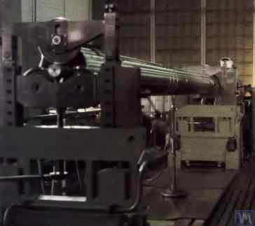
圖 2.15 shows a photograph of a typical Hard Bearing balancing machine manufactured by "K. Schenk." From this figure, it is evident that individual parts of the support, formed by the intricate slots, have varying stiffness. Under the influence of the forces of rotor unbalance, this can lead to deformations (displacements) of some parts of the support relative to others. (In Figure 2.15, the stiffer part of the support is highlighted with a red dotted line, and its relatively compliant part is in blue).

為了測量上述相對變形,硬支承機床可以使用力感測器或各種類型的高靈敏度振動感測器,包括非接觸式振動位移感測器。
Шенк бал

Figure 2.15. Hard Bearing Balancing Machine by "K. Schenk"

As indicated by the analysis of requests received from customers for the "Balanset" series instruments, interest in manufacturing Hard Bearing machines for in-house use has been continuously increasing. This is facilitated by the widespread dissemination of advertising information about the design features of domestic balancing machines, which are used by amateur manufacturers as analogs (or prototypes) for their own developments.

Let's consider some variations of Hard Bearing machines manufactured for the in-house needs of a number of consumers of the "Balanset" series instruments.

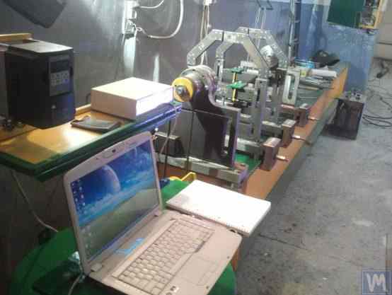
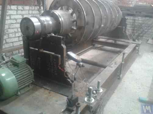
圖 2.16.a – 2.16.d show photographs of a Hard Bearing machine designed for balancing drive shafts, which was manufactured by N. Obyedkov (city of Magnitogorsk). As seen in Fig. 2.16.a, the machine consists of a rigid frame 1, on which supports 2 (two spindle and two intermediate) are installed. The main spindle 3 of the machine is rotated by an asynchronous electric motor 4 via a belt drive. A frequency controller 6 is used to control the rotation speed of the electric motor 4. The machine is equipped with the "Balanset 4" measuring and computing system 5, which includes a measuring unit, a computer, four force sensors, and a phase angle sensor (sensors not shown in Fig. 2.16.a).

2015-01-28 14

圖 2.16.a. 由 N. Obyedkov(馬格尼托哥爾斯克)製造的用於動平衡校正驅動軸的硬支承機床

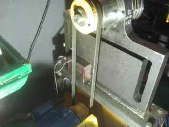
圖 2.16.b 展示了機床前支承的照片,該支承帶有主動軸 3,如前所述,由異步電動機 4 通過皮帶驅動。該支承剛性地安裝在框架上。
2015-01-28 14

圖 2.16.b. 前(主動)軸支承。

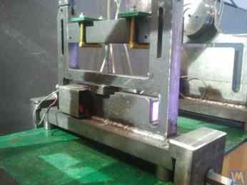
圖 2.16.c 展示了機床兩個可移動中間支承之一的照片。該支承支撐在滑塊 7 上,允許其沿框架導軌縱向移動。該支承包括一個特殊裝置 8,用於安裝和調整被動平衡校正驅動軸的中間軸承的高度。
2015-01-28 14

圖 2.16.c. 機床中間可移動支承

圖 2.16.d shows a photograph of the rear (driven) spindle support, which, like the intermediate supports, allows for movement along the machine frame's guides.

2015-01-28 14

圖 2.16.d. 後(從動)軸支承。

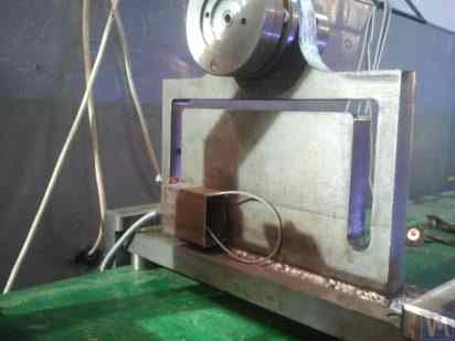
上述所有支承都是安裝在平面底座上的垂直板。板上具有 T 形槽(見圖 2.16.d),將支承分為內部部分 9(更剛性)和外部部分 10(較不剛性)。支承內部和外部部分剛性的差異可能會導致在來自被動平衡校正轉子的不平衡力作用下這些部分發生相對變形。

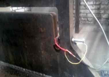
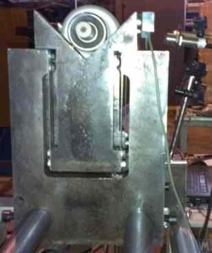
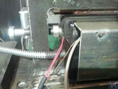
力感測器通常用於測量自製機床中支承的相對變形。圖 2.16.e 展示了力感測器安裝在硬支承動平衡機床支承上的示例。如該圖所示,力感測器 11 通過螺栓 12 壓在支承內部部分的側表面上,該螺栓穿過支承外部部分的螺紋孔。

為了確保螺栓 12 在力感測器 11 的整個平面上均勻施壓,在螺栓和感測器之間放置了一個平墊圈 13。
2015-01-28 14

圖 2.16.d. 支承上力感測器安裝示例。

During the operation of the machine, the forces of imbalance from the balanced rotor act through the support units (spindles or intermediate bearings) on the outer part of the support, which begins to cyclically move (deform) relative to its inner part at the frequency of rotor rotation. This results in a variable force acting on sensor 11, proportional to the imbalance force. Under its influence, an electrical signal proportional to the magnitude of the rotor's imbalance is generated at the output of the force sensor.

Signals from force sensors, installed on all supports, are fed into the machine's measuring and computing system, where they are used to determine the parameters of the corrective weights.

圖 2.17.a. features a photograph of a highly specialized Hard Bearing machine used for balancing "screw" shafts. This machine was manufactured for in-house use at LLC "Ufatverdosplav".

如圖所示,機床的升速機構結構簡化,由以下主要部件組成:

  • 焊接框架 1,作為床身;
  • 兩個固定支承 2,剛性地固定在框架上;
  • 電動機 3,通過皮帶驅動 4 驅動被動平衡校正軸(螺桿)5。

Фото0007 (2).jpg

Figure 2.17.a. Hard Bearing Machine for Balancing Screw Shafts, Manufactured by LLC "Ufatverdosplav"

機床的支承 2 是垂直安裝的帶有 T 形槽的鋼板。每個支承的頂部都有使用滾動軸承製造的支承滾輪,被動平衡校正軸 5 在其上旋轉。

To measure the deformation of the supports, which occurs under the action of rotor imbalance, force sensors 6 are used (see Fig. 2.17.b), which are installed in the slots of the supports. These sensors are connected to the "Balanset 1" device, which is used on this machine as a measuring and computing system.

Despite the relative simplicity of the machine's spin-up mechanism, it enables sufficiently high-quality balancing of screws, which, as seen in Fig. 2.17.a., have a complex helical surface.

According to LLC "Ufatverdosplav," the initial unbalance of the screw was reduced by almost 50 times on this machine during the balancing process.

Фото0009 (1280x905)

圖 2.17.b. 帶有 力感測器的用於動平衡校正螺桿軸的硬支承機床支承

The achieved residual imbalance was 3552 g*mm (19.2 g at a radius of 185 mm) in the first plane of the screw, and 2220 g*mm (12.0 g at a radius of 185 mm) in the second plane. For a rotor weighing 500 kg and operating at a rotational frequency of 3500 RPM, this imbalance corresponds to class G6.3 according to ISO 21940-11 (formerly ISO 1940-1), which meets the requirements set forth in its technical documentation.

An original design (see Fig. 2.18), which involves using a single base for simultaneous installation of supports for two Hard Bearing balancing machines of different sizes, was proposed by S.V. Morozov. The obvious advantages of this technical solution, which allow minimizing the manufacturer's production costs, include:

  • 節省生產空間;
  • 使用一台帶有變頻器的電動機來運行兩台不同的機床;
  • 使用一套測量系統來運行兩台不同的機床。

Figure 2.18. Hard Bearing Balancing Machine ("Tandem"), Manufactured by S.V. Morozov

3. 動平衡機基本單元與機構的結構要求

3.1. 軸承

3.1.1. 軸承設計理論基礎

In the previous section, the main design executions of Soft Bearing and Hard Bearing supports for balancing machines were discussed in detail. A crucial parameter that designers must consider when designing and manufacturing these supports is their natural frequencies of oscillation. This is important because the measurement of not only the amplitude of vibration (cyclic deformation) of the supports but also the phase of vibration is required for calculating the parameters of corrective weights by the machine's measuring and computing systems.

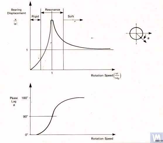
If the natural frequency of a support coincides with the rotation frequency of the balanced rotor (support resonance), accurate measurement of amplitude and phase of vibration is practically impossible. This is clearly illustrated in the graphs showing changes in amplitude and phase of the support's oscillations as a function of the rotational frequency of the balanced rotor (see Fig. 3.1).

從這些圖表可以看出,當被平衡轉子的旋轉頻率接近支撐座振動的自然頻率(即 fp/fo 比值接近 1 時),與支撐座共振振動相關的振幅會顯著增加(見圖 3.1.a)。同時,圖 3.1.b 顯示,在共振區間內,相位角 ∆F° 會發生劇烈變化,變化幅度可達 180°。

換句話說,在共振區間內對任何機構進行動平衡校正時,即使其旋轉頻率發生微小變化,也可能導致其振動振幅與相位測量結果出現顯著的不穩定性,進而造成校正配重參數計算錯誤,並對動平衡品質產生負面影響。

The above graphs confirm earlier recommendations that for Hard Bearing machines, the upper limit of the rotor's operational frequencies should be (at least) 2-3 times lower than the natural frequency of the support, fo. For Soft Bearing machines, the lower limit of permissible operational frequencies of the balanced rotor should (at least) be 2-3 times higher than the natural frequency of the support.

График резонанса

圖 3.1. 顯示動平衡機支撐座振動相對振幅與相位隨旋轉頻率變化關係的圖表。

  • A_d – 支撐座動態振動振幅;
  • e = m*r / M - Specific imbalance of the balanced rotor;
  • m – 轉子的不平衡質量;
  • M – 轉子的質量;
  • r – 轉子上不平衡質量所在的半徑;
  • fp – 轉子的旋轉頻率;
  • fo – 支撐座振動的自然頻率

基於上述資訊,不建議在支撐座的共振區間(圖 3.1 中以紅色標示)內操作機床。圖 3.1 所示的圖表還表明,在轉子不平衡量相同的情況下,軟支撐機床支撐座的實際振動顯著低於硬支撐機床支撐座的振動。

由此可知,用於測量硬支撐機床支撐座振動的感測器,其靈敏度必須高於軟支撐機床所使用的感測器。這一結論得到了實際感測器應用實踐的有力支持,實踐表明,在軟支撐動平衡機中成功使用的絕對振動感測器(振動加速規和/或振動速度感測器),在硬支撐機床上往往無法達到所需的動平衡品質。

在此類機床上,建議使用相對振動感測器,例如力感測器或高靈敏度位移感測器。

3.1.2. 使用計算方法估算支撐座自然頻率

設計人員可以將支撐座簡化為具有單一自由度的振動系統(見圖 2.19.a),該系統由在剛性為 K 的彈簧上振動的質量 M 組成,並使用公式 3.1 對支撐座的自然頻率 fo 進行近似(估算)計算。

fo​=2π1​√(K/M)​​ (3.1)

用於計算的質量 M,對於對稱跨軸承轉子,可通過公式 3.2 進行近似計算。

M=Mo​+Mr​/n​ (3.2)

where Mo​ is the mass of the moving part of the support in kg; Mr​ is the mass of the balanced rotor in kg; n is the number of machine supports involved in the balancing.

支撐座的剛性 K 根據公式 3.3 計算,該計算基於實驗研究結果,實驗中測量了支撐座在靜力 P 負荷下的變形量 ΔL(見圖 3.2.a 和 3.2.b)。

K=P/ΔL (3.3)

where ΔL is the deformation of the support in meters; P is the static force in Newtons.

負荷力 P 的大小可使用測力儀(例如測力計)進行測量。支撐座的位移 ΔL 則使用線性位移測量裝置(例如千分表)確定。

3.1.3. 確定支撐座自然頻率的實驗方法

Given that the above-discussed calculation of natural frequencies of supports, performed using a simplified method, can lead to significant errors, most amateur developers prefer to determine these parameters by experimental methods. For this, they utilize capabilities provided by modern vibration measuring systems of balancing machines, including the "Balanset" series instruments.

3.1.3.1. 使用衝擊激振法確定支撐座自然頻率

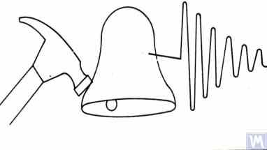
衝擊激振法是確定支撐座或任何其他機械部件振動自然頻率最簡單且最常用的方法。該方法基於以下事實:當任何物體(例如鐘,見圖 3.3)受到衝擊激振時,其響應表現為逐漸衰減的振動響應。振動信號的頻率由物體的結構特性決定,並對應於其自然振動頻率。對於振動的衝擊激振,可以使用任何重型工具,例如橡膠錘或普通鐵錘。
Удар

圖 3.3. 用於確定物體自然頻率的衝擊激振示意圖

錘子的質量應約為被激振物體質量的 10%。為了捕捉振動響應,應在被檢查物體上安裝振動感測器,並使其測量軸與衝擊激振方向對齊。在某些情況下,可以使用噪聲測量設備的麥克風作為感測器,以感知物體的振動響應。

The vibrations of the object are converted into an electrical signal by the sensor, which is then sent to a measuring instrument, such as the input of a spectrum analyzer. This instrument records the time function and the spectrum of the decaying vibrational process (see Fig. 3.4), analysis of which allows determining the frequency (frequencies) of the object's natural vibrations.

圖 3.5. 顯示被檢查結構衰減衝擊振動時間函數圖表與頻譜的程式介面

對圖 3.5 所示頻譜圖(見工作視窗下半部分)的分析表明,被檢查結構自然振動的主要成分(相對於圖表的橫軸確定)出現在 9.5 Hz 的頻率處。此方法可推薦用於研究軟支撐和硬支撐動平衡機支撐座的自然振動。

3.1.3.2. 在惰轉模式下確定支撐座自然頻率

In some cases, the natural frequencies of supports can be determined by cyclically measuring the amplitude and phase of vibration "on the coast." In implementing this method, the rotor installed on the examined machine is initially accelerated to its maximum rotation speed, after which its drive is disconnected, and the frequency of the disturbing force associated with the rotor's imbalance gradually decreases from maximum to the point of stop.

在此情況下,可以通過以下兩個特徵確定支撐座的自然頻率:

  • 通過在共振區間觀察到的振動振幅局部突變;
  • 通過在振幅突變區間觀察到的振動相位劇烈變化(可達 180°)。

In the "Balanset" series devices, the "Vibrometer" mode ("Balanset 1") or the "Balancing. Monitoring" mode ("Balanset 2C" and "Balanset 4") can be used to detect the natural frequencies of objects "on the coast," allowing cyclic measurements of amplitude and phase of vibration at the rotor's rotational frequency.

Furthermore, the "Balanset 1" software additionally includes a specialized "Graphs. Coasting" mode, which allows plotting graphs of changes in amplitude and phase of support vibrations on the coast as a function of changing rotation frequency, significantly facilitating the process of diagnosing resonances.

需要注意的是,出於明顯的原因(見第 3.1.1 節),在惰轉過程中識別支撐座自然頻率的方法僅適用於研究軟支撐動平衡機的情況,在此類機床中,轉子的工作旋轉頻率顯著高於支撐座橫向的自然頻率。

在硬支承機床的情況下,轉子旋轉的工作頻率(激發惰態下支承振動的頻率)顯著低於支承的自然頻率,因此實際上無法使用此方法。

3.1.4. 動平衡機床支承設計與製造的實用建議

3.1.2. 使用計算方法計算支撐座自然頻率

使用上述討論的計算方案計算支撐座自然頻率,可沿兩個方向進行:

  • 沿支撐座的橫向方向,該方向與測量由轉子不平衡力引起的振動的方向一致;
  • 沿軸向方向,該方向與安裝在機床支撐座上的被平衡轉子的旋轉軸線一致。

Calculating the natural frequencies of supports in the vertical direction requires the use of a more complex calculation technique, which (in addition to the parameters of the support and balanced rotor itself) must take into account the parameters of the frame and the specifics of the machine's installation on the foundation. This method is not discussed in this publication. Analysis of formula 3.1 allows for some simple recommendations that should be considered by machine designers in their practical activities. In particular, the natural frequency of a support can be altered by changing its stiffness and/or mass. Increasing the stiffness increases the natural frequency of the support, while increasing the mass decreases it. These changes have a non-linear, square-inverse relationship. For example, doubling the stiffness of the support increases its natural frequency only by a factor of 1.4. Similarly, doubling the mass of the moving part of the support reduces its natural frequency only by a factor of 1.4.

3.1.4.1. 採用平板彈簧的軟支承機床

Several design variations of balancing machine supports made with flat springs have been discussed above in section 2.1 and illustrated in Figures 2.7 - 2.9. According to our information, such designs are most commonly used in machines intended for balancing drive shafts.

As an example, let's consider the spring parameters used by one of the clients (LLC "Rost-Service", St. Petersburg) in the manufacturing of their own machine supports. This machine was intended for balancing 2, 3, and 4-support drive shafts, with a mass not exceeding 200 kg. The geometric dimensions of the springs (height * width * thickness) used in the supports of the leading and driven spindles of the machine, chosen by the client, were respectively 300*200*3 mm.

The natural frequency of the unloaded support, determined experimentally by the impact excitation method using the standard measuring system of the "Balanset 4" machine, was found to be 11 - 12 Hz. At such a natural frequency of vibrations of the supports, the recommended rotational frequency of the balanced rotor during balancing should not be lower than 22-24 Hz (1320 – 1440 RPM).

The geometric dimensions of the flat springs used by the same manufacturer on the intermediate supports were respectively 200*200*3 mm. Moreover, as the studies showed, the natural frequencies of these supports were higher, reaching 13-14 Hz.

Based on the test results, the manufacturers of the machine were advised to align (equalize) the natural frequencies of the spindle and intermediate supports. This should facilitate the selection of the range of operational rotational frequencies of the drive shafts during balancing and avoid potential instabilities of the measuring system's readings due to the supports entering the area of resonant vibrations.

調整平板彈簧支承振動自然頻率的方法顯而易見。此調整可透過改變平板彈簧的幾何尺寸或形狀來實現,例如透過銑削縱向或橫向槽來降低其剛性。

如前所述,可以透過使用第 3.1.3.1 和 3.1.3.2 節中描述的方法來識別支承振動的自然頻率,從而驗證此類調整的結果。

圖 3.6 展示了 A. Sinitsyn 在其一台機床中使用的平板彈簧支承設計的經典版本。如圖所示,該支承包括以下組件:

  • 上板 1;
  • 兩塊平板彈簧 2 和 3;
  • 下板 4;
  • 止擋支架 5。

Figure 3.6 — flat-spring support design for a soft-bearing balancing machine

圖 3.6. 平板彈簧支承設計變體

支承的上板 1 可用於安裝主軸或 intermediate 軸承。根據支承的用途,下板 4 可以剛性地附著在機床導軌上,或安裝在可移動的滑塊上,允許支承沿導軌移動。支架 5 用於安裝支承的鎖定機構,使其在被校正轉子加速和減速期間能夠牢固固定。

Flat springs for Soft Bearing machine supports should be made from leaf-spring or high-quality alloyed steel. The use of ordinary structural steels with a low yield strength is not advisable, as they may develop residual deformation under static and dynamic loads during operation, leading to a reduction in the machine's geometric accuracy and even to the loss of support stability.

Figure 3.7 — balancing machine for electric motor rotors developed by A. Mokhov

圖 3.7. 由 A. Mokhov 開發的電機轉子動平衡機床,已組裝。

Figure 3.8 — balancing machine for turbopump rotors developed by G. Glazov

圖 3.8. 由 G. Glazov(比什凱克)開發的渦輪泵轉子動平衡機床

3.1.4.2. 採用條形彈簧懸掛的軟支承機床支承

在設計用於支承懸掛的條形彈簧時,應注意選擇彈簧條的厚度和寬度,這一方面必須承受轉子對支承的靜態和動態負荷,另一方面必須防止支承懸掛出現扭轉振動的可能性,這種振動表現為軸向偏擺。

Examples of structural implementation of balancing machines using strip spring suspensions are shown in Figures 2.1 - 2.5 (see section 2.1), as well as in Figures 3.7 and 3.8 of this section.

3.1.4.4. Hard Bearing Supports for Machines

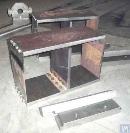
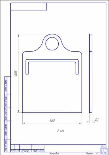
As our extensive experience with clients shows, a significant portion of self-made balancer manufacturers have recently begun to prefer hard bearing machines with rigid supports. In section 2.2, Figures 2.16 – 2.18 depict photographs of various structural designs of machines employing such supports. A typical sketch of a rigid support, developed by one of our clients for their machine construction, is presented in Fig. 3.10. This support consists of a flat steel plate with a P-shaped groove, conventionally dividing the support into "rigid" and "flexible" parts. Under the influence of imbalance force, the "flexible" part of the support can deform relative to its "rigid" part. The magnitude of this deformation, determined by the thickness of the support, depth of the grooves, and width of the bridge connecting the "flexible" and "rigid" parts of the support, can be measured using appropriate sensors of the machine's measuring system. Due to the lack of a method for calculating the transverse stiffness of such supports, taking into account the depth h of the P-shaped groove, width t of the bridge, as well as the thickness of the support r (see Fig. 3.10), these design parameters are typically determined experimentally by developers.

For machines with a balanced rotor mass not exceeding 300 - 500 kg, the thickness of the support can be increased to 30 – 40 mm, and for machines designed for balancing rotors with maximum masses ranging from 1000 to 3000 kg, the thickness of the support can reach 50 – 60 mm or more. As the analysis of the dynamic characteristics of the above-mentioned supports shows, their natural vibration frequencies, measured in the transverse plane (the plane of measurement of relative deformations of the "flexible" and "rigid" parts), usually exceed 100 Hz or more. The natural vibration frequencies of Hard Bearing support stands in the frontal plane, measured in the direction coinciding with the axis of rotation of the balanced rotor, are usually significantly lower. And it is these frequencies that should be primarily considered when determining the upper limit of the operating frequency range for rotating rotors balanced on the machine.

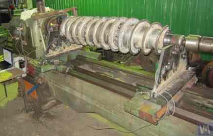
Figure 3.26 — used lathe bed adapted for a hard-bearing auger balancing machine

圖 3.26. 使用二手車床床身製造螺旋鑽桿硬支承動平衡校正機的範例。

Figure 3.27 — used lathe bed adapted for a soft-bearing shaft balancing machine

圖 3.27. 使用二手車床床身製造軸類零件軟支承動平衡校正機的範例。

Figure 3.28 — assembled balancing-machine bed fabricated from steel channels

圖 3.28. 使用槽鋼製造組裝床身的範例

Figure 3.29 — welded balancing-machine bed fabricated from steel channels

圖 3.29. 使用槽鋼製造焊接床身的範例

Figure 3.30 — another welded balancing-machine bed made from steel channels

圖 3.30. 使用槽鋼製造焊接床身的範例

Figure 3.31 — balancing-machine bed made of polymer concrete

圖 3.31. 聚合物混凝土動平衡校正機床身範例

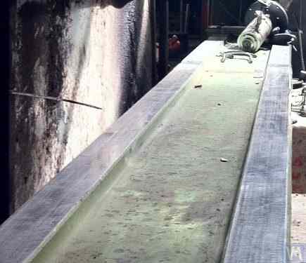
Typically, when manufacturing such beds, their top part is reinforced with steel inserts used as guides on which the support stands of the balancing machine are based. Recently, beds made from polymer concrete with vibration-damping coatings have become widely used. This technology for manufacturing beds is well described online and can be easily implemented by DIY manufacturers. Due to the relative simplicity and low cost of production, these beds have several key advantages over their metal counterparts:

  • 更高的振動振盪阻尼係數;
  • 較低的热導率,確保床身熱變形最小;
  • 更高的耐腐蝕性;
  • 無內部應力。

3.1.4.3. 採用圓柱彈簧製造的軟支承機床支承

圖 3.9 展示了一個軟支承動平衡機床的示例,其支承設計中使用了圓柱壓縮彈簧。此設計方案的主要缺點與前後支承中彈簧變形程度不同有關,這在校正不對稱轉子時,如果支承負荷不均等就會發生。這自然會導致支承不對心和轉子軸在垂直平面內的傾斜。此缺陷的負面後果之一可能是產生導致轉子在旋轉期間軸向移動的力。
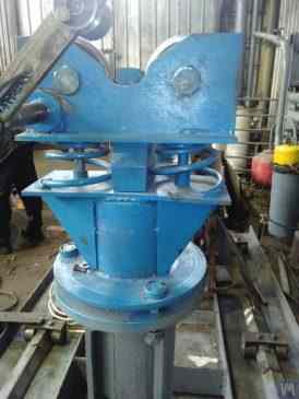
Figure 3.9 — soft-bearing support using cylindrical compression springs

圖 3.9. 採用圓柱彈簧的動平衡機床軟支承結構變體。

3.1.4.4. Hard Bearing Supports for Machines

Чертеж.jpg

圖 3.10. 動平衡機床硬支承草圖

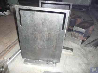
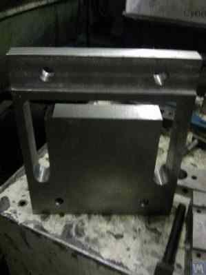
Photographs displaying various implementations of such supports, manufactured for our clients' own machines, are presented in Figures 3.11 and 3.12. Summarizing the data obtained from several of our clients who are machine manufacturers, requirements for the thickness of supports, set for machines of various sizes and load capacities, can be formulated. For example, for machines intended to balance rotors weighing from 0.1 to 50-100 kg, the thickness of the support may be 20 mm.

Figure 3.11 — hard-bearing balancing-machine supports made by A. Sinitsyn

圖 3.11. 由 A. Sinitsyn 製造的動平衡機床硬支承

Figure 3.12 — hard-bearing balancing-machine support made by D. Krasilnikov

圖 3.12. 由 D. Krasilnikov 製造的動平衡機床硬支承

For machines with a balanced rotor mass not exceeding 300 - 500 kg, the thickness of the support can be increased to 30 – 40 mm, and for machines designed for balancing rotors with maximum masses ranging from 1000 to 3000 kg, the thickness of the support can reach 50 – 60 mm or more. As the analysis of the dynamic characteristics of the above-mentioned supports shows, their natural vibration frequencies, measured in the transverse plane (the plane of measurement of relative deformations of the "flexible" and "rigid" parts), usually exceed 100 Hz or more. The natural vibration frequencies of Hard Bearing support stands in the frontal plane, measured in the direction coinciding with the axis of rotation of the balanced rotor, are usually significantly lower. And it is these frequencies that should be primarily considered when determining the upper limit of the operating frequency range for rotating rotors balanced on the machine. As noted above, the determination of these frequencies can be performed by the impact excitation method described in section 3.1.

3.2. 動平衡機床的支承組件

3.2.1. 支承組件的主要類型

在製造硬支承和軟支承動平衡機床時,可以推薦以下用於在支承上安裝和旋轉被校正轉子的知名支承組件類型,包括:

  • 稜柱形支承組件;
  • 帶有滾動滾輪的支承組件;
  • 主軸支承組件。

3.2.1.1. 稜柱形支承組件

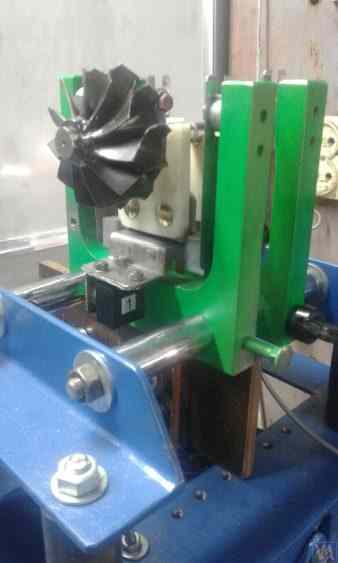
These assemblies, having various design options, are usually installed on supports of small and medium-sized machines, on which rotors with masses not exceeding 50 - 100 kg can be balanced. An example of the simplest version of a prismatic supporting assembly is presented in Figure 3.13. This supporting assembly is made of steel and is used on a turbine balancing machine. A number of manufacturers of small and medium-sized balancing machines, when manufacturing prismatic supporting assemblies, prefer to use non-metallic materials (dielectrics), such as textolite, fluoroplastic, caprolon, etc.

Figure 3.13 — prismatic support assembly for an automotive turbine balancing machine

圖 3.13. 用於汽車渦輪機動平衡機床的稜柱形支承組件執行變體

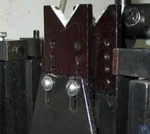
Similar supporting assemblies (see Figure 3.8 above) are implemented, for example, by G. Glazov in his machine, also intended for balancing automobile turbines. The original technical solution of the prismatic supporting assembly, made of fluoroplastic (see Figure 3.14), is proposed by LLC "Technobalance".

Figure 3.14 — Technobalance prismatic support assembly

Fig. 3.14. Prismatic Support Assembly by LLC "Technobalance"

This particular supporting assembly is formed using two cylindrical sleeves 1 and 2, installed at an angle to each other and fixed on supporting axes. The balanced rotor contacts the surfaces of the sleeves along the generating lines of the cylinders, which minimizes the contact area between the rotor shaft and the support, consequently reducing the friction force in the support. If necessary, in case of wear or damage to the support surface in the area of its contact with the rotor shaft, the possibility of wear compensation is provided by rotating the sleeve around its axis by some angle. It should be noted that when using supporting assemblies made of non-metallic materials, it is necessary to provide for the structural possibility of grounding the balanced rotor to the machine body, which eliminates the risk of powerful static electricity charges occurring during operation. This, firstly, helps to reduce electrical interference and disturbances that may affect the performance of the machine's measuring system, and secondly, eliminates the risk of personnel being affected by the action of static electricity.

3.2.1.2. 滾輪支承組件

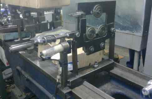
These assemblies are typically installed on supports of machines designed for balancing rotors with masses exceeding 50 kilograms and more. Their use significantly reduces friction forces in the supports compared to prismatic supports, facilitating the rotation of the balanced rotor. As an example, Figure 3.15 shows a design variant of a supporting assembly where rollers are used for the positioning of the product. In this design, standard rolling bearings are used as rollers 1 and 2, the outer rings of which rotate on stationary axes fixed in the body of the machine's support 3. Figure 3.16 depicts a sketch of a more complex design of a roller supporting assembly implemented in their project by one of the self-made manufacturers of balancing machines. As seen from the drawing, in order to increase the load capacity of the roller (and consequently the supporting assembly as a whole), a pair of rolling bearings 1 and 2 is installed in the roller body 3. The practical implementation of this design, despite all its obvious advantages, appears to be a rather complex task, associated with the need for independent fabrication of the roller body 3, to which very high requirements for geometric accuracy and mechanical characteristics of the material are imposed.

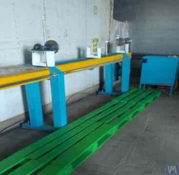
Figure 3.15 — roller support assembly design

圖 3.15. 滾輪支承組件設計示例

Figure 3.16 — roller support assembly with two rolling bearings

圖 3.16. 帶有兩個滾動軸承的滾輪支承組件設計示例

Figure 3.17 presents a design variant of a self-aligning roller supporting assembly developed by the specialists of LLC "Technobalance". In this design, the self-aligning capability of the rollers is achieved by providing them with two additional degrees of freedom, allowing the rollers to make small angular movements around the X and Y axes. Such supporting assemblies, ensuring high precision in the installation of balanced rotors, are usually recommended for use on supports of heavy balancing machines.

Figure 3.17 — self-aligning roller support assembly

圖 3.17. 自對中滾輪支撐組件設計範例

如前所述,滾輪支撐組件通常對精密製造和剛性有相當高的要求。特別是,滾輪徑向偏擺的公差設定不應超過 3-5 微米。

In practice, this is not always achieved even by well-known manufacturers. For example, during the author's testing of the radial runout of a set of new roller support assemblies, purchased as spare parts for the balancing machine model H8V, brand "K. Shenk", the radial runout of their rollers reached 10-11 microns.

3.2.1.3. 主軸支撐組件

在動平衡機上對帶有法蘭安裝的轉子(例如萬向軸)進行動平衡校正時,會使用主軸作為支撐組件,用於定位、安裝和旋轉待平衡產品。

主軸是動平衡機中最複雜且關鍵的組件之一,在很大程度上決定了所需的動平衡品質。

The theory and practice of designing and manufacturing spindles are quite well developed and are reflected in a wide range of publications, among which, the monograph "Details and Mechanisms of Metal-Cutting Machine Tools" [1], edited by Dr. Eng. D.N. Reshetov, stands out as the most useful and accessible for developers.

在動平衡機主軸的設計與製造中,應優先考慮以下主要要求:

a) 提供足夠的主軸組件結構剛性,以防止在待平衡轉子的不平衡力影響下可能發生的不可接受的變形;

b) 確保主軸旋轉軸位置的穩定性,其特徵在於主軸的徑向、軸向和端面偏擺的允許值;

c) 確保主軸軸頸以及用於安裝待平衡產品的座面和支撐表面具有適當的耐磨性。

The practical implementation of these requirements is detailed in Section VI "Spindles and Their Supports" of work [1].

特別是,其中包含驗證主軸剛性和旋轉精度的方法論、軸承選擇建議、主軸材料選擇及其硬化方法,以及關於此主題的其他許多有用資訊。

文獻 [1] 指出,在大多數類型金屬切削機床的主軸設計中,主要採用雙軸承方案。

圖 3.18 展示了用於銑床主軸的此類雙軸承方案設計方案的範例(詳細資訊請參見文獻 [1])。

此方案相當適合用於製造動平衡機主軸,其設計方案範例如下圖 3.19-3.22 所示。
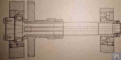
Figure 3.18 — two-bearing milling-machine spindle arrangement

圖 3.18. 雙軸承銑床主軸草圖

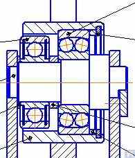
圖 3.19 展示了動平衡機驅動主軸組件的一種設計方案,該組件在兩個徑向推力軸承上旋轉,每個軸承都有其獨立的軸承座 1 和 2。法蘭 4(用於萬向軸的法蘭安裝)和皮帶輪 5(用於通過 V 帶驅動將旋轉從電動機傳遞到主軸)安裝在主軸軸 3 上。
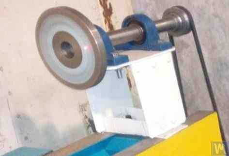
Figure 3.19 — spindle with two independent bearing supports

圖 3.19. 兩個獨立軸承支撐座上的主軸設計範例

圖 3.20 和 3.21 展示了兩種密切相關的驅動主軸組件設計。在兩種情況下,主軸軸承都安裝在一個共同的軸承座 1 中,該軸承座具有一個貫通的軸向孔,用於安裝主軸軸。在此孔的入口和出口處,軸承座具有特殊的孔(圖中未顯示),用於容納徑向推力軸承(滾子或球軸承)和特殊的法蘭蓋 5,用於固定軸承的外圈。
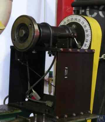
Figure 3.20 — drive spindle with two bearings in a common housing

圖 3.20. 安裝在共同軸承座中的兩個軸承支撐座上的驅動主軸設計範例 1
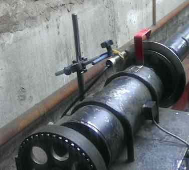
Figure 3.21 — alternative drive spindle with two bearings in a common housing

圖 3.21. 安裝在共同軸承座中的兩個軸承支撐座上的驅動主軸設計範例 2

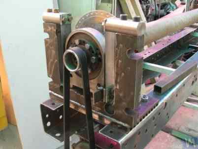
與前一版本(見圖 3.19)一樣,主軸軸上安裝了一個面盤 2,用於驅動軸的法蘭安裝,以及一個皮帶輪 3,用於通過帶式驅動將旋轉從電動機傳遞到主軸。主軸軸上還固定了一個支臂 4,用於確定主軸的角度位置,在動平衡過程中於轉子上安裝試重和校正配重時使用。
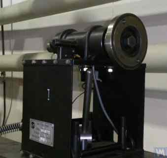
Figure 3.22 — driven rear spindle design

圖 3.22. 從動(後)主軸設計範例

圖 3.22 展示了機器從動(後)主軸組件的一種設計方案,其與驅動主軸的區別僅在於缺少驅動皮帶輪和支臂,因為它們不需要。
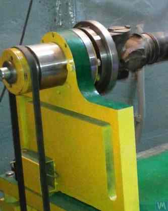
Figure 3.23 — implementation of a driven rear spindle

Figure 3.23. Example of Design Execution of a Driven (Rear) Spindle

圖 3.20 – 3.22所示,上述主軸組件使用特殊的夾具(綁帶)6 安裝在動平衡機的軟支撐座上。如有必要,也可以使用其他安裝方法,以確保主軸組件在支撐座上的定位具有適當的剛性和精度。

圖 3.23 展示了一種與該主軸類似的法蘭安裝設計,可用於將其安裝在動平衡機的硬支撐座上。

3.2.1.3.4. Calculating Spindle Stiffness and Radial Runout

For determining spindle rigidity and expected radial runout, formula 3.4 can be used (see calculation scheme in Figure 3.24):

Y = P * [1/jB * ((c+g)² + jB/jA) / c²] (3.4)

其中:

  • Y - elastic displacement of the spindle at the end of the spindle console, cm;
  • P - calculated load acting on the spindle console, kg;
  • A - rear bearing support of the spindle;
  • B - front bearing support of the spindle;
  • g - length of the spindle console, cm;
  • c - distance between supports A and B of the spindle, cm;
  • J1 - averaged moment of inertia of the spindle section between supports, cm⁴;
  • J2 - averaged moment of inertia of the spindle console section, cm⁴;
  • jB and jA - stiffness of bearings for the front and rear supports of the spindle, respectively, kg/cm.

透過轉換公式 3.4,可求得所需的主軸組件剛性計算值 jшп 可確定為:

jшп = P / Y, kg/cm (3.5)

考慮文獻 [1] 對中型動平衡機的建議,此值不應低於 50 kg/µm。

For radial runout calculation, formula 3.5 is used:

∆ = ∆B + g/c * (∆B + ∆A) (3.5)

其中:

  • ∆ 為主軸懸臂末端的徑向偏擺,µm;
  • ∆B 為前主軸軸承的徑向偏擺,µm;
  • ∆A 為後主軸軸承的徑向偏擺,µm;
  • g 為主軸懸臂長度,cm;
  • c 為主軸軸承 A 與 B 之間的距離,cm。

3.2.1.3.5. 確保主軸動平衡要求

Spindle assemblies of balancing machines must be well-balanced, as any actual imbalance will transfer to the rotor being balanced as additional error. When setting technological tolerances for the residual imbalance of the spindle, it is generally advised that the precision class of its balancing should be at least 1 - 2 classes higher than that of the product being balanced on the machine.

考慮上述主軸的設計特徵,其動平衡校正應在兩個校正平面進行。

3.2.1.3.6. 確保主軸軸承的負荷能力與耐久性要求

When designing spindles and selecting bearing sizes, it is advisable to preliminarily assess the durability and load capacity of the bearings. The methodology for performing these calculations can be detailed in ISO 281 "Rolling Bearings - Dynamic Load Ratings and Rating Life" [3], as well as in numerous (including digital) rolling bearing handbooks.

3.2.1.3.7. 確保主軸軸承可接受溫升要求

根據文獻 [1] 的建議,主軸軸承外圈的允許最高溫升不應超過 70°C。然而,為確保高品質的動平衡,建議外圈溫升不應超過 40 – 45°C。

3.2.1.3.8. 選擇皮帶驅動類型與主軸驅動皮帶輪設計

設計動平衡機的驅動主軸時,建議採用平皮帶驅動以確保其旋轉。此類驅動用於主軸運轉的正確應用範例見 圖 3.20 與 3.23. Using v-belt or toothed belt drives is undesirable, as they can apply additional dynamic loads to the spindle due to geometric inaccuracies in the belts and pulleys, which in turn can lead to additional measurement errors during balancing. Recommended requirements for pulleys for flat drive belts are outlined in the national standard GOST 17383-73 "Pulleys for flat drive belts" [4].

驅動皮帶輪應配置於主軸後端,盡可能靠近軸承組件(懸伸量最小化)。如 圖 3.19所示主軸製造中採用的懸伸式皮帶輪配置設計,可視為不成功,因為它會顯著增加作用於主軸軸承的動態驅動負荷力矩。

此設計的另一個重大缺點是使用 V 型皮帶驅動,其製造與組裝誤差也可能成為主軸額外不良負荷的來源。

3.3. 機床(機架)

機床是動平衡機的主要支撐結構,其支撐座柱與驅動馬達等主要元件均安裝於其上。在選定或製造動平衡機機床時,必須確保其滿足多項要求,包括必要的剛性、幾何精度、抗震性,以及導軌的耐磨性。

實務經驗顯示,在製造自用設備時,最常見的床身選項如下:

  • 來自二手金屬切削機床(車床、木工機床等)的鑄鐵床身;
  • 基於槽鋼組裝的床身,採用螺栓連接;
  • 基於槽鋼焊接的床身;
  • 帶有減震塗層的聚合物混凝土床身。

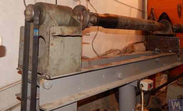
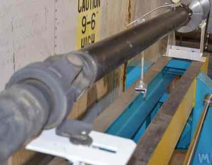
Figure 3.25 — woodworking-machine bed adapted for balancing cardan shafts

圖 3.25. 使用二手木工機床床身製造萬向軸動平衡校正設備的範例。

3.4. 動平衡校正機驅動裝置

正如對客戶在製造動平衡校正機時使用的設計方案的分析所示,他們在設計驅動裝置時主要專注於使用配備變頻器的交流馬達。這種方法能夠以最低的成本實現廣泛的可調轉速範圍。用於旋轉待平衡轉子的主驅動馬達的功率通常根據這些轉子的質量來選擇,大約可以為:

  • 0.25 - 0.72 kW for machines designed for balancing rotors with a mass of ≤ 5 kg;
  • 0.72 - 1.2 kW for machines designed for balancing rotors with a mass > 5 ≤ 50 kg;
  • 1.2 - 1.5 kW for machines designed for balancing rotors with a mass > 50 ≤ 100 kg;
  • 1.5 - 2.2 kW for machines designed for balancing rotors with a mass > 100 ≤ 500 kg;
  • 2.2 - 5 kW for machines designed for balancing rotors with a mass > 500 ≤ 1000 kg;
  • 5 - 7.5 kW for machines designed for balancing rotors with a mass > 1000 ≤ 3000 kg.

這些馬達應牢固地安裝在機床床身或其基礎上。在安裝到設備上(或在安裝現場)之前,主驅動馬達及其輸出軸上安裝的皮帶輪應仔細進行動平衡校正。為了減少變頻器引起的電磁干擾,建議在其輸入和輸出端安裝網路濾波器。這些可以是驅動器製造商提供的標準現成產品,或使用鐵氧體環製作的自制濾波器。

4. 動平衡機的測量系統

Most amateur manufacturers of balancing machines, who contact LLC "Kinematics" (Vibromera), plan to use the "Balanset" series measurement systems manufactured by our company in their designs. However, there are also some customers who plan to manufacture such measuring systems independently. Therefore, it makes sense to discuss the construction of a measuring system for a balancing machine in more detail. The main requirement for these systems is the need to provide high-precision measurements of the amplitude and phase of the rotational component of the vibrational signal, which appears at the rotation frequency of the balanced rotor. This goal is usually achieved by using a combination of technical solutions, including:

  • 使用具有高信號轉換係數的振動感測器;
  • 使用現代激光相位角感測器;
  • 創建(或使用)允許對感測器信號進行放大和數位轉換的硬體(一次信號處理);
  • Implementation of software processing of the vibrational signal, which should allow for the high-resolution and stable extraction of the rotational component of the vibrational signal, manifesting at the rotation frequency of the balanced rotor (secondary processing).

Below, we consider known variants of such technical solutions, implemented in a number of well-known balancing instruments.

4.1. 振動感測器的選擇

在動平衡機的測量系統中,可以使用各種類型的振動感測器(傳感器),包括:

  • 振動加速感測器(加速規);
  • 振動速度感測器;
  • 振動位移感測器;
  • 力感測器。

4.1.1. 振動加速感測器

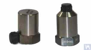
Among vibration acceleration sensors, piezo and capacitive (chip) accelerometers are the most widely used, which can be effectively used in Soft Bearing type balancing machines. In practice, it is generally permissible to use vibration acceleration sensors with conversion coefficients (Kpr) ranging from 10 to 30 mV/(m/s²). In balancing machines that require particularly high balancing accuracy, it is advisable to use accelerometers with Kpr reaching levels of 100 mV/(m/s²) and above. As an example of piezo accelerometers that can be used as vibration sensors for balancing machines, Figure 4.1 shows the DN3M1 and DN3M1V6 piezo accelerometers manufactured by LLC "Izmeritel".

Figure 4.1 — DN 3M1 and DN 3M1V6 piezoelectric accelerometers

圖 4.1. DN 3M1 和 DN 3M1V6 壓電加速規

要將此類感測器連接到振動測量儀器和系統,必須使用外部或內置電荷放大器。

Figure 4.2. Capacitive Accelerometers AD1 Manufactured by LLC "Kinematics" (Vibromera)

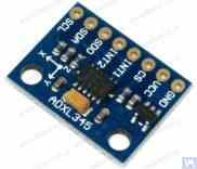
應該指出的是,這些感測器,包括廣泛使用的市場電容式加速規 ADXL 345 板(見圖 4.3),與壓電加速規相比具有幾個顯著優勢。具體來說,在技術特性相似的情況下,它們的價格便宜 4 到 8 倍。此外,它們不需要使用壓電加速規所需的昂貴且挑剔的電荷放大器。

在動平衡機的測量系統中同時使用這兩種類型的加速規時,通常會對感測器信號進行硬體積分(或雙重積分)。
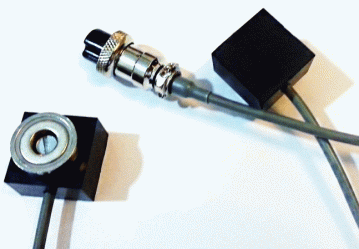
Figure 4.2 — assembled AD1 capacitive accelerometers

圖 4.2. AD 1 電容式加速規,組裝完成。

Figure 4.3 — ADXL345 capacitive accelerometer board

圖 4.3. ADXL 345 電容式加速規板。

在這種情況下,與振動加速度成正比的最初感測器信號,相應地轉換為與振動速度或位移成正比的信號。當在低速動平衡機的測量系統中使用加速規時,振動信號的雙重積分程序尤為相關,因為在平衡過程中,轉子旋轉頻率的較低範圍可達 120 rpm 及以下。在動平衡機的測量系統中使用電容式加速規時,應該考慮到,積分後,它們的信號可能包含低頻干擾,表現為 0.5 到 3 Hz 的頻率範圍。這可能會限制計劃使用這些感測器的機器的平衡低頻範圍。

4.1.2. 振動速度感測器

4.1.2.1. 感應式振動速度感測器。

這些感測器包括一個感應線圈和一個磁芯。當線圈相對於靜止的磁芯振動(或磁芯相對於靜止的線圈振動)時,線圈中會感應出電動勢,其電壓與感測器可動部件的振動速度成正比。感應感測器的轉換係數(Кпр)通常相當高,可達數十甚至數百 mV/mm/sec。具體來說,Schenck T77 型感測器的轉換係數為 80 mV/mm/sec,而 IRD Mechanalysis 544M 型感測器的轉換係數為 40 mV/mm/sec。在某些情況下(例如在 Schenck 動平衡機中),使用帶有機械放大器的特殊高靈敏度感應振動速度感測器,其中 Кпр 可超過 1000 mV/mm/sec。如果在動平衡機的測量系統中使用感應振動速度感測器,也可以對與振動速度成正比的電信號進行硬體積分,將其轉換為與振動位移成正比的信號。
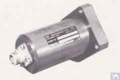
Figure 4.4 — IRD Mechanalysis model 544M vibration velocity sensor

圖 4.4. IRD Mechanalysis 的 544M 型感測器。

Figure 4.5 — Schenck model T77 vibration velocity sensor

圖 4.5. Schenck 的 T77 型感測器

應該指出的是,由於其生產的勞動強度,感應式振動速度感測器相當稀缺且昂貴。因此,儘管這些感測器具有明顯的優勢,但業餘動平衡機製造商很少使用它們。

4.2. 相位角感測器

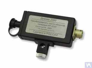
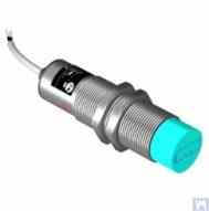
For synchronizing the vibration measurement process with the rotation angle of the balanced rotor, phase angle sensors, such as laser (photoelectric) or inductive sensors, are used. These sensors are manufactured in various designs by both domestic and international producers. The price range for these sensors can vary significantly, from approximately 40 to 200 dollars. An example of such a device is the phase angle sensor manufactured by "Diamex," shown in figure 4.11.

Figure 4.11 — Diamex phase-angle sensor

Figure 4.11: Phase Angle Sensor by "Diamex"

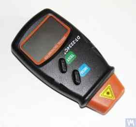
As another example, Figure 4.12 shows a model implemented by LLC "Kinematics" (Vibromera), which uses laser tachometers of the DT 2234C model made in China as phase angle sensors. 此感測器的明顯優點包括:

  • 寬廣的運作範圍,允許測量轉子旋轉頻率從 2.5 到 99,999 轉每分鐘,解析度不低於一轉;
  • 數位顯示;
  • 輕鬆設定測速儀以進行測量;
  • 價格實惠且市場成本低;
  • 修改相對簡單,以便整合到動平衡機的測量系統中。

https://images.ua.prom.st/114027425_w640_h2048_4702725083.jpg?PIMAGE_ID=114027425

圖 4.12:DT 2234C 型雷射測速儀

在某些情況下,如果出於任何原因不適合使用光學雷射感測器,則可以替換為感應式非接觸位移感測器,例如前面提到的 ISAN E41A 型號或其他製造商的類似產品。

4.3. 振動感測器中的訊號處理特性

為了在動平衡設備中精確測量振動訊號旋轉分量的振幅和相位,通常會結合使用硬體和軟體處理工具。這些工具能夠:

  • Broadband hardware filtering of the sensor's analog signal;
  • Amplification of the sensor's analog signal;
  • 對類比訊號進行積分和/或雙重積分(如有必要);
  • 使用追蹤濾波器對類比訊號進行窄帶濾波;
  • 訊號的類比轉數位轉換;
  • 數位訊號的同步濾波;
  • 數位訊號的諧波分析。

4.3.1. 寬頻訊號濾波

This procedure is essential for cleansing the vibration sensor signal of potential interferences that may occur at both the lower and upper bounds of the device's frequency range. It is advisable for the measuring device of a balancing machine to set the lower limit of the band-pass filter to 2-3 Hz and the upper limit to 50 (100) Hz. "Lower" filtering helps suppress low-frequency noises which may appear at the output of various types of sensor measuring amplifiers. "Upper" filtering eliminates the possibility of interference due to combination frequencies and potential resonant vibrations of individual mechanical components of the machine.

4.3.2. 感測器類比訊號的放大

If there is a need to increase the sensitivity of the balancing machine's measuring system, the signals from the vibration sensors to the input of the measuring unit can be amplified. Both standard amplifiers with a constant gain and multistage amplifiers, whose gain can be programmatically changed depending on the real signal level from the sensor, can be used. An example of a programmable multistage amplifier includes amplifiers implemented in voltage measurement converters like E154 or E14-140 by LLC "L-Card".

4.3.3. 積分

如前所述,建議在動平衡機的測量系統中對振動感測器訊號進行硬體積分和/或雙重積分。因此,初始的加速規訊號(與振動加速度成正比)可以轉換為與振動速度(積分)或振動位移(雙重積分)成正比的訊號。同樣地,振動速度感測器訊號在積分後可以轉換為與振動位移成正比的訊號。

4.3.4. 使用追蹤濾波器對類比訊號進行窄帶濾波

To reduce interference and improve the quality of vibration signal processing in the measuring systems of balancing machines, narrowband tracking filters can be used. The central frequency of these filters is automatically tuned to the rotation frequency of the balanced rotor using the rotor's revolution sensor signal. Modern integrated circuits, such as MAX263, MAX264, MAX267, MAX268 by "MAXIM", can be used to create such filters.

4.3.5. 訊號的類比轉數位轉換

Analog-to-digital conversion is a crucial procedure that ensures the possibility of improving the quality of vibration signal processing during the measurement of amplitude and phase. This procedure is implemented in all modern measuring systems of balancing machines. An example of effective implementation of such ADCs includes the voltage measurement converters type E154 or E14-140 by LLC "L-Card", used in several measuring systems of balancing machines manufactured by LLC "Kinematics" (Vibromera). Additionally, LLC "Kinematics" (Vibromera) has experience using cheaper microprocessor systems based on "Arduino" controllers, the PIC18F4620 microcontroller by "Microchip", and similar devices.

4.1.2.2. Vibration Velocity Sensors Based on Piezoelectric Accelerometers

A sensor of this type differs from a standard piezoelectric accelerometer by having a built-in charge amplifier and integrator within its housing, which allows it to output a signal proportional to vibration velocity. For example, piezoelectric vibration velocity sensors manufactured by domestic producers (ZETLAB company and LLC "Vibropribor") are shown in Figures 4.6 and 4.7.

Figure 4.6 — ZETLAB AV02 vibration velocity sensor

圖 4.6. ZETLAB(俄羅斯)的 AV02 型感測器

Figure 4.7 — Vibropribor DVST-2 vibration velocity sensor

Figure 4.7. Model DVST 2 sensor by LLC "Vibropribor"

此類感測器由各種生產商(包括國內和國外)生產,目前廣泛使用,特別是在便攜式振動設備中。這些感測器的成本相當高,即使來自國內製造商,每個也可達 20,000 到 30,000 盧布。

4.1.3. 位移感測器

In the measurement systems of balancing machines, non-contact displacement sensors – capacitive or inductive – can also be used. These sensors can operate in static mode, allowing the registration of vibrational processes starting from 0 Hz. Their use can be particularly effective in the case of balancing low-speed rotors with rotation speeds of 120 rpm and below. The conversion coefficients of these sensors can reach 1000 mV/mm and higher, which provides high accuracy and resolution in measuring displacement, even without additional amplification. An obvious advantage of these sensors is their relatively low cost, which for some domestic manufacturers does not exceed 1000 rubles. When using these sensors in balancing machines, it is important to consider that the nominal working gap between the sensor's sensitive element and the surface of the vibrating object is limited by the diameter of the sensor coil. For example, for the sensor shown in Figure 4.8, model ISAN E41A by "TEKO," the specified working gap is typically 3.8 to 4 mm, which allows for the measurement of displacement of the vibrating object in the range of ±2.5 mm.

Figure 4.8 — TEKO ISAN E41A inductive displacement sensor

圖 4.8. TEKO(俄羅斯)的 ISAN E41A 型感應位移感測器

4.1.4. 力感測器

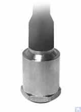
如前所述,力感測器用於安裝在硬支承動平衡機上的測量系統中。這些感測器,特別是由於其製造簡單且成本相對較低,通常是壓電力感測器。此類感測器的示例如圖 4.9 和 4.10 所示。
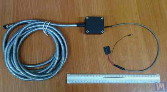
Figure 4.9 — Kinematika SD-1 force sensor

圖 4.9. Kinematika LLC 的 SD 1 力感測器

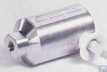
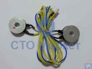
Figure 4.10 — force sensor for automotive balancing machines

Figure 4.10: Force Sensor for Automotive Balancing Machines, Sold by "STO Market"

由眾多國內外生產商生產的應變片力感測器,也可用於測量硬支承動平衡機支撐中的相對變形。

4.4. Functional Scheme of the Measuring System of the Balancing Machine, "Balanset 2"

The "Balanset 2" measuring system represents a modern approach to integrating measurement and computing functions in balancing machines. This system provides automatic calculation of corrective weights using the influence coefficient method and can be adapted for various machine configurations.

The functional scheme includes signal conditioning, analog-to-digital conversion, digital signal processing, and automatic calculation algorithms. The system can handle both two-plane and multi-plane balancing scenarios with high precision.

4.5. 轉子動平衡中使用的校正配重參數計算

The calculation of corrective weights is based on the influence coefficient method, which determines how the rotor responds to test weights in different planes. This method is fundamental to all modern balancing systems and provides accurate results for both rigid and flexible rotors.

4.5.1. 雙支撐轉子動平衡任務及其解決方法

For dual-support rotors (the most common configuration), the balancing task involves determining two corrective weights - one for each correction plane. The influence coefficient method uses the following approach:

  1. Initial measurement (Run 0): Measure vibration without any trial weights
  2. First trial run (Run 1): Add known trial weight to Plane 1, measure response
  3. Second trial run (Run 2): Move trial weight to Plane 2, measure response
  4. 計算: Software calculates permanent correction weights based on measured responses

The mathematical foundation involves solving a system of linear equations relating the trial weight influences to the required corrections in both planes simultaneously.

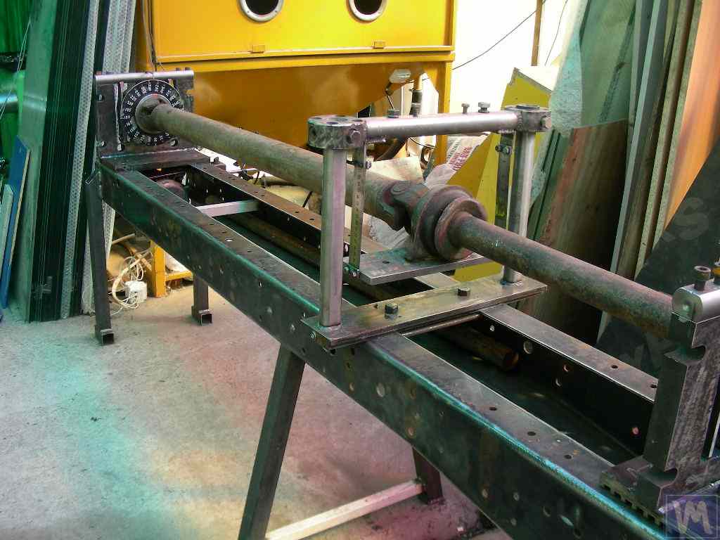
圖 3.26 和 3.27 展示了使用車床床身的範例,基於這些床身製造了專門用於螺旋鑽桿的硬支承動平衡校正機,以及用於圓柱形轉子的通用軟支承動平衡校正機。對於 DIY 製造商而言,此類解決方案能夠以最少的时间和成本創建剛性支撐系統,並可安裝各種類型的支撐架(硬支承和軟支承)。在這種情況下,製造商的主要任務是確保(並在必要時恢復)支撐架所依賴的機床導軌的幾何精度。在 DIY 生產條件下,通常使用精細刮研來恢復導軌所需的幾何精度。

圖 3.28 展示了一個由兩根槽鋼組裝而成的床身版本。在製造此床身時,使用了可拆卸的螺栓連接,這使得在組裝過程中無需額外的工藝操作即可將床身變形降至最低或完全消除。為了確保指定床身導軌的正確幾何精度,可能需要對所使用的槽鋼上翼緣進行機械加工(研磨、精細銑削)。

圖 3.29 和 3.30 展示了焊接床身的變體,同樣由兩根槽鋼製成。此類床身的製造技術可能需要一系列額外的操作,例如熱處理以消除焊接過程中產生的內部應力。與組裝床身一樣,為了確保焊接床身導軌的正確幾何精度,應計劃對所使用的槽鋼上翼緣進行機械加工(研磨、精細銑削)。

4.5.2. 多支撐轉子動平衡方法論

Multi-support rotors (three or four bearing points) require more complex balancing procedures. Each support point contributes to the overall dynamic behavior, and the correction must account for interactions between all planes.

The methodology extends the two-plane approach by:

  • Measuring vibration at all support points
  • Using multiple trial weight positions
  • Solving larger systems of linear equations
  • Optimizing correction weight distribution

For cardan shafts and similar long rotors, this approach typically achieves residual imbalance levels corresponding to ISO quality grades G6.3 or better.

4.5.3. 多支撐轉子動平衡計算器

Specialized calculation algorithms have been developed for three-support and four-support rotor configurations. These calculators are implemented in Balanset-4 software and can handle complex rotor geometries automatically.

The calculators account for:

  • Variable support stiffness
  • Cross-coupling between correction planes
  • Optimization of weight placement for accessibility
  • Verification of calculated results

5. 動平衡機運行與精度檢查建議

The accuracy and reliability of a balancing machine depend on many factors, including the geometric accuracy of its mechanical components, dynamic characteristics of supports, and operational capability of the measuring system. Regular verification of these parameters ensures consistent balancing quality and helps identify potential issues before they affect production.

5.1. 機器幾何精度檢查

Geometric accuracy verification includes checking the alignment of supports, parallelism of guides, and concentricity of spindle assemblies. These checks should be performed during initial setup and periodically during operation to ensure maintained accuracy.

5.2. 機器動態特性檢查

Dynamic characteristics verification involves measuring natural frequencies of supports and frame components to ensure they are properly separated from operating frequencies. This prevents resonance issues that can compromise balancing accuracy.

5.3. 測量系統運行能力檢查

The measuring system verification includes sensor calibration, phase alignment verification, and signal processing accuracy checks. This ensures reliable measurement of vibration amplitude and phase at all operating speeds.

5.4. Checking the Accuracy Characteristics according to ISO 21940-21 (formerly ISO 2953)

ISO 21940-21 (formerly ISO 2953) provides standardized procedures for verifying balancing machine accuracy using calibrated test rotors. These procedures help validate the machine's performance against internationally recognized standards.

參考文獻

  1. Reshetov D.N. (editor). "Details and Mechanisms of Metal-Cutting Machine Tools." Moscow: Mashinostroenie, 1972.
  2. Kellenberger W. "Spiral Grinding of Cylindrical Surfaces." Machinery, 1963.
  3. ISO 281 "Rolling Bearings - Dynamic Load Ratings and Rating Life."
  4. GOST 17383-73 (national standard) "Pulleys for flat drive belts."
  5. ISO 21940-11 (formerly ISO 1940-1) "Mechanical vibration - Rotor balancing - Part 11: Procedures and tolerances for rotors with rigid behaviour."
  6. ISO 21940-21 (formerly ISO 2953) "Mechanical vibration - Rotor balancing - Part 21: Description and evaluation of balancing machines."

附錄 1:三支撐軸動平衡參數計算演算法

Three-support rotor balancing requires solving a system of three equations with three unknowns. This appendix provides the mathematical foundation and step-by-step calculation procedure for determining corrective weights in three correction planes.

A1.1. Mathematical Foundation

For a three-support rotor, the influence coefficient matrix relates the trial weight effects to vibration responses at each bearing location. The general form of the equation system is:

[V₁] = [A₁₁ A₁₂ A₁₃] [W₁]
[V₂] = [A₂₁ A₂₂ A₂₃] [W₂]
[V₃] = [A₃₁ A₃₂ A₃₃] [W₃]

其中:

  • V₁, V₂, V₃ - vibration vectors at supports 1, 2, and 3
  • W₁, W₂, W₃ - correction weights in planes 1, 2, and 3
  • Aᵢⱼ - influence coefficients relating weight j to vibration at support i

A1.2. Calculation Procedure

  1. Initial measurements: Record vibration amplitude and phase at all three supports without trial weights
  2. Trial weight sequence: Apply known trial weight to each correction plane sequentially, recording vibration changes
  3. Influence coefficient calculation: Determine how each trial weight affects vibration at each support
  4. Matrix solution: Solve the system of equations to find optimal correction weights
  5. Weight placement: Install calculated weights at specified angles
  6. 驗證: Confirm residual vibration meets specifications

A1.3. Special Considerations for Three-Support Rotors

Three-support configurations are commonly used for long cardan shafts where intermediate support is required to prevent excessive deflection. Key considerations include:

  • Intermediate support stiffness affects overall rotor dynamics
  • Support alignment is critical for accurate results
  • Trial weight magnitude must cause measurable response at all supports
  • Cross-coupling between planes requires careful analysis

附錄 2:四支撐軸動平衡參數計算演算法

Four-support rotor balancing represents the most complex common configuration, requiring solution of a 4x4 matrix system. This configuration is typical for very long rotors such as paper mill rolls, textile machinery shafts, and heavy industrial rotors.

A2.1. Extended Mathematical Model

The four-support system extends the three-support model with additional equations accounting for the fourth bearing location:

[V₁] = [A₁₁ A₁₂ A₁₃ A₁₄] [W₁]
[V₂] = [A₂₁ A₂₂ A₂₃ A₂₄] [W₂]
[V₃] = [A₃₁ A₃₂ A₃₃ A₃₄] [W₃]
[V₄] = [A₄₁ A₄₂ A₄₃ A₄₄] [W₄]

A2.2. Sequential Trial Weight Procedure

The four-support procedure requires five measurement runs:

  1. Run 0: Initial measurement at all four supports
  2. 運轉 1: Trial weight in Plane 1, measure all supports
  3. 運轉 2: Trial weight in Plane 2, measure all supports
  4. 運轉 3: Trial weight in Plane 3, measure all supports
  5. 第 4 次運轉: Trial weight in Plane 4, measure all supports

A2.3. Optimization Considerations

Four-support balancing often allows multiple valid solutions. The optimization process considers:

  • Minimizing total correction weight mass
  • Ensuring accessible weight placement locations
  • Balancing manufacturing tolerances and costs
  • Meeting specified residual vibration limits

附錄 3:動平衡計算器使用指南

The Balanset balancer calculator automates the complex mathematical procedures described in Appendices 1 and 2. This guide provides practical instructions for using the calculator effectively with DIY balancing machines.

A3.1. Software Setup and Configuration

  1. Machine definition: Define machine geometry, support locations, and correction planes
  2. Sensor calibration: Verify sensor orientation and calibration factors
  3. Trial weight preparation: Calculate appropriate trial weight mass based on rotor characteristics
  4. 安全驗證: Confirm safe operating speeds and weight attachment methods

A3.2. Measurement Sequence

The calculator guides the user through the measurement sequence with real-time feedback on measurement quality and suggestions for improving signal-to-noise ratio.

A3.3. Results Interpretation

The calculator provides multiple output formats:

  • Graphical vector displays showing correction requirements
  • Numerical weight and angle specifications
  • Quality metrics and confidence indicators
  • Suggestions for improving measurement accuracy

A3.4. Troubleshooting Common Issues

Common problems and solutions when using the calculator with DIY machines:

  • Insufficient trial weight response: Increase trial weight mass or check sensor mounting
  • Inconsistent measurements: Verify mechanical integrity, check for resonance conditions
  • Poor correction results: Verify angle measurement accuracy, check for cross-coupling effects
  • Software errors: Check sensor connections, verify input parameters, ensure stable RPM

便攜式平衡機 & 振動分析儀 Balanset-1A

振動感測器

光學感測器(雷射轉速計)

Balanset-4

磁吸支架 Insize-60-kgf

反光膠帶

動平衡機「Balanset-1A」OEM

Author of the article: Feldman Valery Davidovich

Editor and translation: Nikolai Andreevich Shelkovenko

對於可能的翻譯錯誤,我深表歉意。

WhatsApp
Balanset-1A · €1975Ask engineer