On Balancing Aircraft Propellers in Field Conditions
Summary: This engineering report documents the first successful application of the portable Balanset-1 device for field balancing of aircraft propellers. Work was conducted on Yak-52 (two-blade propeller) and Su-29 (three-blade MTV-9-K-C/CL 260-27 propeller) aircraft equipped with M-14P engines in May–July 2014. Key findings: propeller vibration on the Yak-52 was reduced from 10.2 to 4.2 mm/sec; on the Su-29, from 6.7 to 1.5 mm/sec (more than 4× reduction). The report also presents detailed vibration spectrum analysis at multiple operating modes and identifies dominant vibration sources including crankshaft harmonics and structural resonances.
1. Foreword
Two and a half years ago, our enterprise began the serial production of the "Balanset-1" device, designed for balancing rotary mechanisms in their own bearings.
To date, more than 180 sets have been produced. They are effectively used in various industries, including the production and operation of fans, blowers, electric motors, machine spindles, pumps, crushers, separators, centrifuges, cardan and crankshaft assemblies, and similar mechanisms.
Recently, Vibromera has received a large number of inquiries from organizations and individuals regarding the possibility of using our equipment for balancing aircraft and helicopter propellers in field conditions.
Unfortunately, our specialists, despite many years of experience in balancing various machines, had never previously dealt with this specific problem. The advice and recommendations we could give our customers were therefore quite general and did not always allow them to effectively solve the task at hand.
This situation began to change for the better this spring, thanks to the active involvement of V.D. Chvokov, who organized and took part alongside us in the work on balancing the propellers of Yak-52 and Su-29 aircraft, which he pilots.
During this work, certain skills were acquired and a technology for balancing aircraft propellers in field conditions using the "Balanset-1" device was developed, including:
- determining the locations and methods for installing (mounting) vibration and phase angle sensors on the aircraft;
- determining the resonance frequencies of several structural elements of the aircraft (engine suspension, propeller blades);
- identifying the engine rotation frequencies (operating modes) that ensure the minimum achievable residual imbalance during balancing;
- establishing tolerances for the residual imbalance of the propeller.
In addition, interesting data on the vibration levels of aircraft equipped with M-14P engines were obtained.
Below are the report materials compiled from the results of this work. In addition to the balancing results, they present data from the vibration surveys of Yak-52 and Su-29 aircraft, obtained during ground and flight tests. These data may be of interest both to aircraft pilots and to specialists involved in their maintenance.
2. Balancing and Vibration Survey of the Yak-52
2.1. Introduction
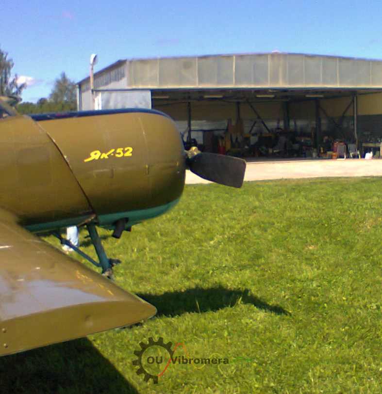
In May–July 2014, work was carried out on the vibration survey of the Yak-52 aircraft, equipped with the M-14P aviation engine, and the balancing of its two-blade propeller.
Balancing was performed in one plane using the "Balanset-1" kit, serial no. 149.
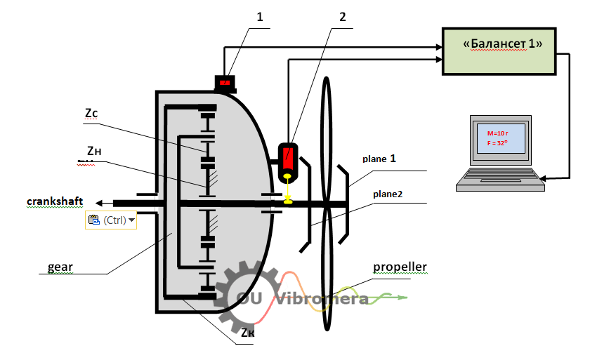
The measurement scheme is shown in Fig. 2.1. During balancing, vibration sensor (accelerometer) 1 was installed on the front cover of the engine gearbox using a magnetic mount on a specially designed bracket. Laser phase angle sensor 2 was also installed on the gearbox cover and oriented toward the reflective mark applied to one of the propeller blades.
Analog signals from the sensors were transmitted via cables to the measuring unit of the "Balanset-1" device, where preliminary digital processing was performed. These signals in digital form then entered the computer, where software processing was carried out and the mass and angle of the correction weight needed to compensate for the propeller imbalance were calculated.
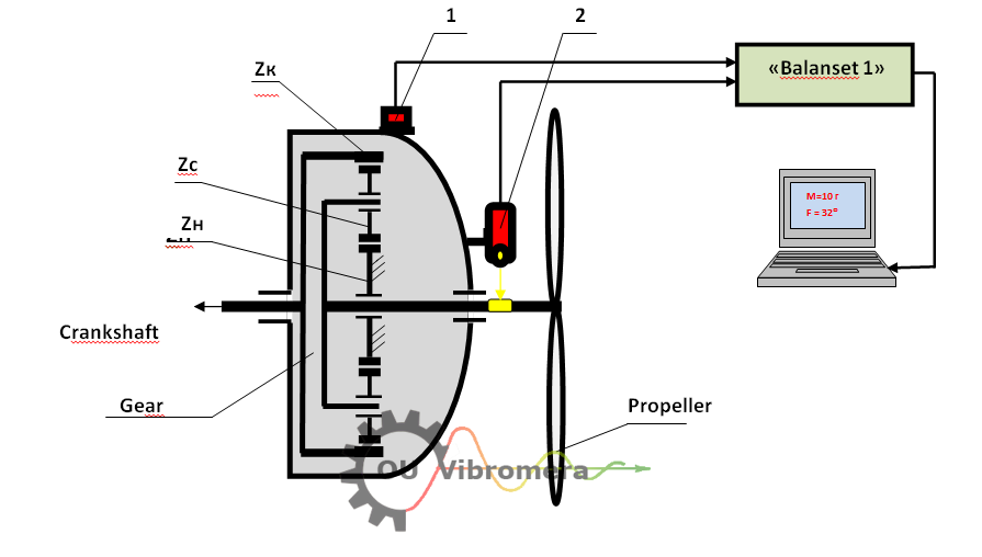
Zk — main gear wheel; Zs — satellites; Zn — stationary gear wheel.
During this work, taking into account the experience gained from balancing the propellers of both the Su-29 and the Yak-52, a number of additional studies were conducted:
- determining the natural frequencies of the engine and propeller oscillations of the Yak-52;
- measuring the vibration magnitude and spectral composition in the second pilot's cabin during flight after propeller balancing;
- measuring vibration after propeller balancing and after adjusting the tightening force of the engine shock absorbers.
2.2. Natural Frequencies of Engine and Propeller Oscillations
The natural frequencies of the engine oscillations, mounted on shock absorbers in the aircraft body, were determined using a spectrum analyzer AD-3527 by A&D (Japan) through impact excitation.
In the spectrum of natural oscillations of the Yak-52 engine suspension (Fig. 2.2), four main frequencies were identified: 20 Hz, 74 Hz, 94 Hz, 120 Hz.
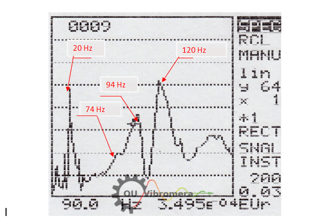
The frequencies 74 Hz, 94 Hz, and 120 Hz are likely related to the characteristics of the engine mounting (suspension) to the aircraft body. The frequency 20 Hz is most likely associated with the natural oscillations of the aircraft on its landing gear chassis.
The natural frequencies of the propeller blades were also determined using the impact excitation method. Four main frequencies were identified: 36 Hz, 80 Hz, 104 Hz, and 134 Hz.
The data on the natural frequencies of oscillations of the engine suspension and propeller blades are of importance primarily for choosing the propeller rotation frequency during balancing. The main condition in selecting this frequency is to ensure maximum detuning from the natural frequencies of oscillations of the aircraft's structural elements, since at resonant frequencies the accuracy and repeatability of vibration measurements can be significantly impaired.
In addition, knowledge of the natural frequencies of individual components can be useful for identifying the causes of sharp increases in vibration (resonance phenomena) at various engine speed modes, which may arise during operation of the aircraft.
2.3. Balancing Results
As noted above, propeller balancing was performed in one plane, thereby compensating for the force imbalance of the propeller dynamically.
Dynamic balancing in two planes (which would additionally compensate for moment imbalance) was not feasible, since the propeller design on the Yak-52 allows for only one correction plane.
Balancing was performed at a rotation frequency of 1150 rpm (60%), at which the most stable vibration measurements, both in amplitude and phase, were obtained from run to run.
The classic "two-run" scheme was used:
- During the first run, the amplitude and phase of vibration at the propeller rotation frequency in the initial state were determined.
- During the second run, the amplitude and phase of vibration after installing a trial mass of 7 g on the propeller were determined.
- Based on these data, the software calculated: correction mass M = 19.5 g at angle F = 32°.
Due to the design features of the propeller, which did not allow installing the correction weight at the required angle of 32°, two equivalent weights were installed:
- M1 = 14 g at angle F1 = 0°
- M2 = 8.3 g at angle F2 = 60°
Result: After installing the correction weights, vibration at 1150 rpm decreased from 10.2 mm/sec to 4.2 mm/sec. The actual imbalance decreased from 2340 g·mm to 963 g·mm.
2.4. Vibration at Other Operating Modes
The results of vibration checks at other engine operating modes during ground tests are presented in Table 2.1. As can be seen, the balancing positively affected the vibration of the Yak-52 at all modes.
| # | Power, % | RPM | RMS Vibration Velocity, mm/sec |
|---|---|---|---|
| 1 | 60 | 1153 | 4.2 |
| 2 | 65 | 1257 | 2.6 |
| 3 | 70 | 1345 | 2.1 |
| 4 | 82 | 1572 | 1.25 |
Moreover, during ground tests, a clear trend of substantial vibration reduction with increasing propeller rotation frequency was identified. This can be explained by a greater detuning of the propeller rotation frequency from the aircraft's natural oscillation frequency on the chassis (presumably 20 Hz), which occurs at higher rotation frequencies.
2.5. In-Flight Vibration Before and After Shock Absorber Adjustment
In addition to the ground vibration tests after propeller balancing (section 2.3), vibration measurements of the Yak-52 were also conducted in flight.
Vibration in flight was measured in the second pilot's cabin in the vertical direction using a portable spectrum analyzer AD-3527 by A&D (Japan) in the frequency range from 5 to 200 (500) Hz. Measurements were taken at five main engine speed modes: 60%, 65%, 70%, 82%, and 94% of maximum rotation frequency.
The results, obtained before adjusting the shock absorbers, are presented in Table 2.2.
| # | Propeller speed | Vibration spectrum components, frequency (CPM) / amplitude (mm/sec) |
VΣ, mm/sec |
||||||||
|---|---|---|---|---|---|---|---|---|---|---|---|
| % | RPM | Vp1 | Vn | Vc1 | Vp2 | Vc2 | Vp4 | Vc3 | Vp5 | ||
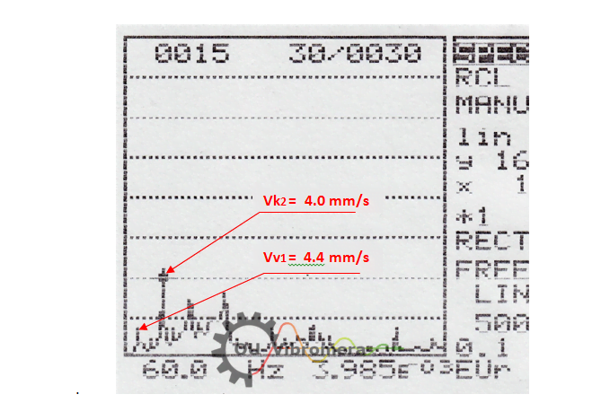
| 1 | 60 | 1155 | 1155 4.4 |
1560 1.5 |
1755 1.0 |
2310 1.5 |
3510 4.0 |
4620 1.3 |
5265 0.7 |
5775 0.9 |
6.1 |
| 2 | 65 | 1244 | 1244 3.5 |
1680 1.2 |
1890 2.1 |
2488 1.2 |
3780 4.1 |
4976 0.4 |
5670 1.2 |
6.2 | |
| 3 | 70 | 1342 | 1342 2.8 |
1860 0.4 |
2040 3.2 |
2684 0.4 |
4080 2.9 |
5369 2.3 |
5.0 | ||
| 4 | 82 | 1580 | 1580 4.7 |
2160 2.9 |
2400 1.1 |
3160 0.4 |
4800 12.5 |
13.7 | |||
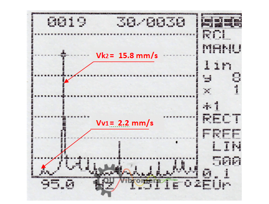
| 5 | 94 | 1830 | 1830 2.2 |
2484 3.4 |
2760 1.7 |
3660 2.8 |
5520 15.8 |
7320 3.7 |
17.1 | ||
Vp = propeller harmonics (1st, 2nd, 4th, 5th) Vn = compressor/frequency sensor Vc1, Vc2, Vc3 = crankshaft 1st, 2nd, 3rd Upper value = frequency (CPM), lower = amplitude (mm/sec).
As seen from Table 2.2, the main vibration components appear at the propeller rotation frequency Vp1, the crankshaft frequency Vc1, the air compressor (and/or frequency sensor) drive Vn, and their higher harmonics.
Maximum total vibration VΣ was found at 82% (1580 rpm) and 94% (1830 rpm) modes. The dominant component at these modes appears at the 2nd harmonic of the crankshaft rotation frequency Vc2, reaching 12.5 mm/sec at 4800 cycles/min and 15.8 mm/sec at 5520 cycles/min.
It can be assumed that this component is associated with the piston group (impact processes occurring during the double movement of the pistons per one crankshaft revolution). The sharp increase at the 82% (first nominal) and 94% (take-off) modes is most likely caused not by piston group defects, but by resonant oscillations of the engine on its shock absorbers. This conclusion is supported by the natural frequency measurements, which revealed engine suspension frequencies at 74 Hz (4440 cycles/min), 94 Hz (5640 cycles/min), and 120 Hz (7200 cycles/min). Two of these — 74 Hz and 94 Hz — are close to the 2nd crankshaft harmonic frequencies at the first nominal and take-off operating modes.
Due to the significant vibrations found at Vc2, the tightening force of the engine shock absorbers was checked and adjusted. The comparative results are presented in Table 2.3.
| # | % | RPM (before / after) |
Vp1 | Vc2 | ||
|---|---|---|---|---|---|---|
| Before | After | Before | After | |||
| 1 | 60 | 1155 / 1140 | 1155 4.4 |
1140 3.3 |
3510 3.0 |
3480 3.6 |
| 2 | 65 | 1244 / 1260 | 1244 3.5 |
1260 3.5 |
3780 4.1 |
3840 4.3 |
| 3 | 70 | 1342 / 1350 | 1342 2.8 |
1350 3.3 |
4080 2.9 |
4080 1.2 |
| 4 | 82 | 1580 / 1590 | 1580 4.7 |
1590 4.2 |
4800 12.5 |
4830 16.7 |
| 5 | 94 | 1830 / 1860 | 1830 2.2 |
1860 2.7 |
5520 15.8 |
5640 15.2 |
Upper value = frequency (CPM), lower = amplitude (mm/sec).
As seen from Table 2.3, the absorber adjustment did not lead to significant changes in the main vibration components of the aircraft.
It should also be noted that the propeller imbalance component Vp1 at modes 82% and 94% is respectively 3–7 times lower than Vc2 at those modes. At other flight modes, Vp1 ranges from 2.8 to 4.4 mm/sec, and its changes between modes are mainly determined not by the quality of balancing, but by the degree of detuning from the natural frequencies of the aircraft's structural elements.
2.6. Conclusions
2.6.1.
Balancing the propeller of the Yak-52 at a rotation frequency of 1150 rpm (60%) allowed reducing the vibration at the propeller rotation frequency from 10.2 mm/sec to 4.2 mm/sec. With due consideration of the experience accumulated during the balancing of propellers of both the Yak-52 and Su-29 aircraft using the "Balanset-1" device, there is a realistic possibility of achieving an even greater reduction of the vibration level — in particular, by selecting a higher rotation frequency of the propeller during balancing, which would allow to a greater degree detuning from the natural frequency of oscillations of the aircraft at 20 Hz (1200 cycles/min) identified during the measurements.
2.6.2.
As the flight vibration tests show (see Tables 2.2 and 2.3), the vibration spectra of the Yak-52 aircraft contain, in addition to the vibration at the propeller rotation frequency Vp1, several other significant components — associated with the crankshaft Vc1, Vc2, Vc3, the engine piston group, and the air compressor (and/or frequency sensor) drive Vn.
At the speed modes of 60%, 65%, and 70%, these components are comparable in magnitude to the propeller imbalance component Vp1. Consequently, even complete elimination of the vibration caused by propeller imbalance would allow reducing the total vibration of the aircraft at these modes by no more than approximately 1.5 times.
2.6.3.
Maximum total vibration VΣ of the Yak-52 aircraft was found at the speed modes of 82% (1580 rpm of the propeller) and 94% (1830 rpm of the propeller). The dominant component of this vibration appears at the 2nd harmonic of the crankshaft rotation frequency Vc2, at frequencies of 4800 cycles/min and 5520 cycles/min respectively, at which it reaches values of 12.5 mm/sec and 15.8 mm/sec.
As shown in sections 2.5 and 2.2, the sharp increase in this component at the indicated modes is most likely caused not by defects of the piston group, but by resonant oscillations of the engine on its shock absorbers. The adjustment of the absorber tightening force, performed during the tests, did not lead to significant changes in vibration levels.
This situation can presumably be considered a design oversight (konstruktivny proschet) of the aircraft developers, admitted during the selection of the engine mounting (suspension) system in the aircraft body.
2.6.4.
The data obtained during the course of propeller balancing and the additionally performed vibration tests suggest that periodic vibration monitoring can be useful for the diagnostic assessment of the technical condition of the aircraft engine, including the evaluation of the state of the piston group, crankshaft, engine bearings, and the air compressor drive.
Such work can be performed, for example, using the "Balanset-1" device (currently produced as the Balanset-1A), in the software of which the function of spectral vibration analysis is implemented.
3. Balancing the MTV-9-K-C/CL 260-27 Propeller and Vibration Survey of the Su-29
3.1. Introduction
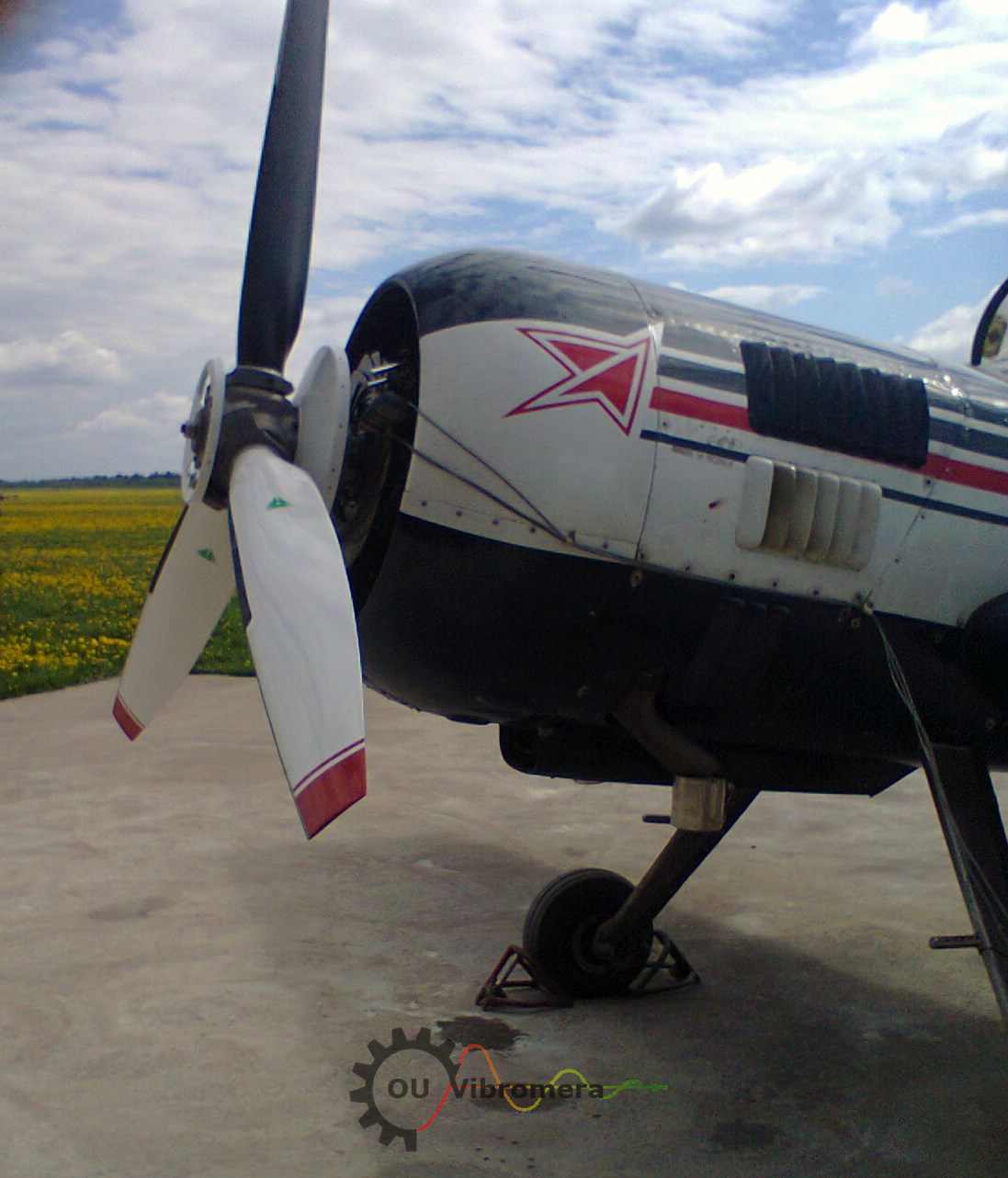
On June 15, 2014, work was carried out on the balancing of the three-bladed propeller of the type MTV-9-K-C/CL 260-27, installed on the M-14P aviation engine of the Su-29 aerobatic aircraft.
According to the data provided by the manufacturer (MT-Propeller), the indicated propeller had been preliminarily statically balanced, as evidenced by the presence on the propeller in plane 1 of a corrective weight installed at the manufacturing plant.
Balancing of the propeller, installed directly on the output shaft of the Su-29 gearbox (i.e. in the place of its permanent installation), was carried out using the "Balanset-1" vibration balancing kit, serial no. 149.
The measurement scheme (Fig. 3.1) was in general similar to that used for the Yak-52. Vibration sensor (accelerometer) 1 was installed on the housing of the engine gearbox using a magnetic mount on a specially designed bracket. Laser phase angle sensor 2 was likewise mounted on the gearbox housing and oriented toward the reflective mark applied to one of the propeller blades. Analog signals from the sensors were transmitted via cables to the measuring unit of the "Balanset-1" device, where preliminary digital processing was performed. Thereafter, the signals in digital form entered the computer, where software processing was carried out and the mass and angle of the correction weight needed to compensate for the propeller imbalance were calculated.
Zk — main gear wheel; Zc — satellites; Zn — stationary gear wheel.
Before this work, and taking into account the experience from balancing the Yak-52 propeller, additional studies were conducted:
- determining the natural frequencies of the Su-29 engine and propeller oscillations;
- checking the magnitude and spectral composition of baseline vibration in the second pilot's cabin before balancing.
3.2. Natural Frequencies of Engine and Propeller Oscillations
Using the same impact excitation method with the AD-3527 analyzer, six main frequencies were identified in the engine suspension spectrum (Fig. 3.2): 16 Hz, 22 Hz, 37 Hz, 66 Hz, 88 Hz, 120 Hz.
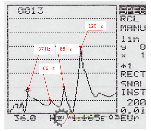
The frequencies 66 Hz, 88 Hz, and 120 Hz are presumably directly related to the peculiarities of the engine mounting (suspension) system in the aircraft body. The frequencies 16 Hz and 22 Hz are most likely associated with the natural oscillations of the aircraft as a whole on its chassis. As for the frequency of 37 Hz, it is probably related to the natural frequency of oscillations of the propeller blade of the aircraft.
This last assumption is confirmed by the results of measurements of the natural frequencies of oscillations of the propeller blades (Fig. 3.3), in the spectrum of which three main frequencies were identified: 37 Hz, 100 Hz, and 174 Hz.
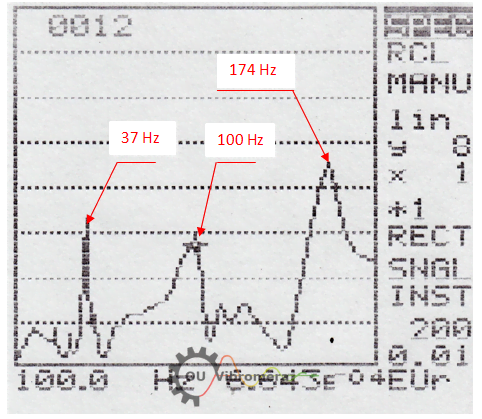
Knowledge of the natural frequencies of the engine suspension and propeller blades of the Su-29 is of substantial practical importance. First, it enables a justified selection of the propeller rotation frequency for balancing, ensuring maximum detuning from the structural resonances of the aircraft. Second, it provides the necessary basis for the correct interpretation and diagnosis of vibration causes observed at various engine operating modes, as will be demonstrated in the subsequent sections of this report.
3.3. Baseline Cabin Vibration Before Balancing
Prior to performing the balancing procedure, measurements of the baseline vibration levels in the second pilot's cabin of the Su-29 were conducted. As in the case of the Yak-52, vibration was measured in the vertical direction using the portable spectrum analyzer AD-3527 by A&D (Japan) in the frequency range from 5 to 200 Hz. Measurements were performed at four main engine speed modes, corresponding to 60%, 65%, 70%, and 82% of the maximum rotation frequency of the propeller.
The results of these measurements are presented in Table 3.1.
| # | Propeller speed | Vibration spectrum components, frequency (CPM) / amplitude (mm/sec) |
VΣ, mm/sec |
||||||||
|---|---|---|---|---|---|---|---|---|---|---|---|
| % | RPM | Vp1 | Vn | Vc1 | Vp3 | Vc2 | Vp4 | Vc3 | V? | ||
| 1 | 60 | 1150 | 1150 5.4 |
1560 2.6 |
1740 2.0 |
3450 | 3480 4.2 |
6120 2.8 |
8.0 | ||
| 2 | 65 | 1240 | 1240 5.7 |
1700 2.4 |
1890 1.3 |
3720 | 3780 8.6 |
10.6 | |||
| 3 | 70 | 1320 | 1320 2.8 |
1800 2.5 |
2010 0.9 |
3960 | 4020 10.8 |
11.5 | |||
| 4 | 82 | 1580 | 1580 3.2 |
2160 1.5 |
2400 3.0 |
4740 | 4800 8.5 |
9.7 | |||
Vp = propeller harmonics (1st, 3rd, 4th) Vn = compressor/frequency sensor Vc1, Vc2 = crankshaft 1st, 2nd V? = unidentified component. Upper value = frequency (CPM), lower = amplitude (mm/sec).
The main vibration components appear at the propeller rotation frequency Vp1, crankshaft Vc1, compressor drive Vn, and the 2nd crankshaft harmonic Vc2 (which in the three-bladed propeller case may also coincide with the blade-pass frequency Vp3).
In the 60% mode spectrum, an unidentified component at 6120 cycles/min was also found, possibly caused by resonance at approximately 100 Hz — one of the propeller blade's natural frequencies.
Maximum total vibration (11.5 mm/sec) was found at the 70% mode. The dominant component at this mode is Vc2 at 4020 cycles/min, reaching 10.8 mm/sec. This sharp increase at 70% is likely due to resonant oscillations of the engine suspension near 67 Hz (4020 cycles/min).
It should also be noted that, in addition to the impact excitations from the piston group, the vibration in this frequency region may also be influenced by aerodynamic forces at the blade-pass frequency of the propeller (Vp3). At the 65% and 82% modes, a noticeable increase in the Vc2 (Vp3) component is also observed, which can likewise be explained by resonant oscillations of individual aircraft components.
The propeller imbalance component Vp1 ranged from 2.4 to 5.7 mm/sec across modes before balancing, generally lower than Vc2 at the corresponding modes. Its variation between modes is determined not only by the quality of balancing, but also by the degree of detuning from the natural frequencies of the aircraft's structural elements.
3.4. Balancing Results
Balancing of the propeller was performed in one plane at a rotation frequency of 1350 rpm, using two measurement runs (the classic method of influence coefficients). The full protocol of balancing is given in Appendix 1.
The balancing procedure consisted of the following operations:
- During the first run (initial state), the amplitude and phase of vibration at the propeller rotation frequency were determined.
- During the second run, the amplitude and phase of vibration after installing a trial mass of known weight on the propeller were determined.
- Based on these measurement results, the software calculated the mass and installation angle of the corrective weight in plane 1, necessary for compensating the propeller imbalance.
Result: After installing the corrective weight of 40.9 g, vibration decreased from 6.7 mm/sec to 1.5 mm/sec. At other speed modes, vibration associated with propeller imbalance remained within 1–2.5 mm/sec.
Verification of the balancing quality in flight was not carried out due to accidental damage to the propeller during a training flight.
Significant deviation from factory balancing. It should be noted that the result obtained during the field balancing differs substantially from the result of balancing performed at the manufacturing plant:
- The vibration at the propeller rotation frequency after field balancing at the place of permanent installation (on the output shaft of the Su-29 gearbox) was reduced by more than 4 times compared to the initial state (i.e. compared to the factory-balanced condition);
- The corrective weight installed during field balancing was shifted by approximately 130° relative to the corrective weight installed at the manufacturing plant (MT-Propeller).
The corrective weight installed at the manufacturing plant was not removed from the propeller during the additional field balancing.
The reasons for the indicated discrepancy may be the following:
- errors of the measuring system of the balancing stand at the manufacturing plant (this reason appears to be the least probable);
- geometric errors (inaccuracies) of the mounting surfaces of the spindle of the balancing machine at the manufacturing plant, causing radial runout of the propeller on the spindle;
- geometric errors (inaccuracies) of the mounting surfaces of the output shaft of the gearbox on the Su-29 aircraft, causing radial runout of the propeller when installed on the gearbox shaft.
3.5. Conclusions
3.5.1.
Balancing the propeller of the Su-29 aircraft in one plane at a propeller rotation frequency of 1350 rpm (70%) allowed reducing the vibration at the propeller rotation frequency from 6.7 mm/sec in the initial state to 1.5 mm/sec after balancing. The vibration associated with propeller imbalance at other speed modes of the engine also decreased significantly and remained within 1–2.5 mm/sec.
3.5.2.
In order to clarify the reasons for the unsatisfactory results of balancing the propeller at the manufacturing plant (MT-Propeller), it is necessary to check the radial runout of the propeller on the output shaft of the engine gearbox of the Su-29 aircraft.
Appendix 1: Balancing Protocol
BALANCING PROTOCOL
MTV-9-K-C/CL 260-27 propeller of the Su-29 aerobatic aircraft
1. Customer: V.D. Chvokov
2. Installation site: Output shaft of the Su-29 gearbox
3. Propeller type: MTV-9-K-C/CL 260-27
4. Balancing method: Assembled on-site (in own bearings), one plane
5. Balancing RPM: 1350
6. Balancing device: "Balanset-1", serial no. 149, Vibromera
7. Standards used: ISO 1940-1 — Balance quality requirements for rigid rotors.
8. Date: 15.06.2014
9. Summary of balancing results:
| # | Measurement | Vibration, mm/sec | Imbalance, g·mm |
|---|---|---|---|
| 1 | Before balancing * | 6.7 | 6135 |
| 2 | After balancing | 1.5 | 1350 |
| ISO 1940 tolerance for class G 6.3 | 1500 | ||
* Balancing was performed with the factory-installed corrective weight remaining on the propeller.
10. Findings:
10.1. The residual vibration (imbalance) after balancing the propeller on the Su-29 gearbox output shaft was reduced by more than 4 times compared to the initial state.
10.2. The corrective weight parameters (mass, angle) differ significantly from those installed by the manufacturer (MT-Propeller). An additional corrective weight of 40.9 g was installed, shifted by 130° from the factory weight. The factory weight was not removed.
To identify the specific cause, it is necessary to:
- check the measuring system and geometric accuracy of the spindle mounting on the manufacturer's balancing machine;
- check the radial runout of the propeller on the Su-29 gearbox output shaft.
Executor:
Chief Specialist, Vibromera
V.D. Feldman
Frequently Asked Questions
What is field propeller balancing and why does it matter?
Field propeller balancing is performed with the propeller installed on the aircraft, running at operational speed. Unlike factory static balancing (done off the aircraft), it accounts for actual installation conditions: gearbox tolerances, mounting geometry, and the complete aircraft dynamic system. In our Su-29 case, the corrective weight required in the field was shifted 130° from the factory-installed weight — demonstrating that factory balancing alone may be insufficient for optimal results.
What equipment is needed for aircraft propeller balancing?
The Balanset-1A balancing kit includes a vibration sensor (accelerometer), a laser phase angle sensor (tachometer), a USB interface unit for digital signal processing, and a computer running balancing software. Sensors are mounted to the engine gearbox housing using a magnetic stand and bracket. A reflective tape mark on one propeller blade serves as the phase reference.
How is the balancing RPM selected?
The rotation frequency for balancing must provide maximum detuning from the natural frequencies of the aircraft's structural elements (engine suspension, propeller blades, aircraft on its chassis). Additionally, the chosen RPM should yield stable vibration measurements in amplitude and phase from run to run. For the Yak-52, 1150 rpm (60%) was selected; for the Su-29, 1350 rpm (70%).
What vibration levels are acceptable after balancing?
Per ISO 1940 for Class G 6.3, residual imbalance should not exceed 1500 g·mm. In practice, good results yield vibration below 2.5 mm/sec RMS at the propeller rotation frequency. On the Su-29, balancing achieved 1.5 mm/sec with 1350 g·mm residual imbalance — within ISO tolerance.
Can propeller balancing eliminate all aircraft vibration?
No. The vibration spectrum of a piston aircraft contains components from the crankshaft, piston group, air compressor drive, and structural resonances. Our Yak-52 analysis showed that even complete elimination of propeller imbalance would reduce total vibration by no more than about 1.5 times at most operating modes. At the 82% and 94% modes, the 2nd crankshaft harmonic dominated total vibration by a factor of 3–7 over the propeller component.
How often should aircraft propellers be balanced?
Propellers should be balanced during major inspections, after repairs or damage, and whenever excessive vibration is noticed. Aerobatic aircraft may require more frequent balancing due to higher stress loading. Periodic vibration monitoring using spectral analysis (available in the Balanset-1A software) can also serve as a diagnostic tool for engine condition assessment.
What Balanset models are available for propeller balancing?
Vibromera offers several models suitable for propeller and rotor balancing: the Balanset-1A (€1,975) is a dual-channel portable system used in this study; the Balanset-1A OEM (€1,735) is an integration-ready version for workshops and maintenance organizations; the Balanset-4 (€6,803) is a four-channel system for complex multi-plane balancing tasks. All models include spectral vibration analysis capability and are supplied with vibration sensors, laser tachometer, magnetic mounting hardware, and PC software.
Can Vibromera perform on-site propeller balancing as a service?
Yes. In addition to manufacturing and selling balancing equipment, Vibromera provides field balancing services for rotating machinery. For organizations that do not require their own balancing equipment, or for complex one-time tasks, Vibromera's specialists can perform on-site dynamic balancing using the same Balanset instrumentation described in this report. Service inquiries can be directed through the contact page.
