4.1. “Balanset-1A” include (fig. 4.1) USB interface unit (1), two accelerometers (2) and (3), phase reference marker (4) and portable PC (not supplied) (5).
Delivery set also includes the magnetic stand (6) used for mounting the phase reference marker and digital scales 7.
X1 and X2 connectors intended for connection of the vibration sensors respectively to 1 and 2 measuring channels, and the X3 connector used for connection of the phase reference marker.
The USB cable provides power supply and connection of the USB interface unit to the computer.

Fig. 4.1. Delivery set of the “Balanset-1A”
Mechanical vibrations cause an electrical signal proportional to the vibration acceleration on the output of the vibration sensor. Digitized signals from ADC module transferred via USB to the portable PC (5). Phase reference marker generate the pulse signal used to calculate rotation frequency and vibration phase angle.
Windows based software provides solution for single-plane and two-plane balancing, spectrum analyzing, charts, reports, storage of influence coefficients
5.1. Attention! When operating on 220V electrical safety regulations must be observed. It is not allowed to repair the device when connected to 220 V.
5.2. If you use the appliance in a low quality AC power and weights of network interference it is recommended to use a standalone power from computer’s battery pack.
Installation disk (flash drive) contains the following files and folders:
Bs1Av###Setup – folder with “Balanset-1A” balancing software (### – version number)
ArdDrv– USB drivers
EBalancer_manual.pdf – this manual
Bal1Av###Setup.exe – setup file. This file contains all archived files and folders mentioned above. ###– version of “Balanset-1A” software.
Ebalanc.cfg – sensitivity value
Bal.ini – some initialization data
For installing drivers and specialized software run file Bal1Av###Setup.exe and follow setup instructions by pressing buttons «Next», «ОК» etc.
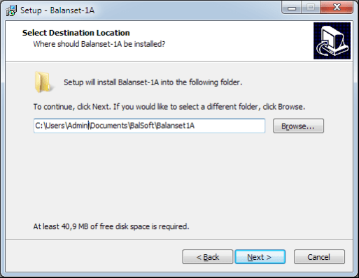
Choose setup folder. Usually the given folder should not be changed.
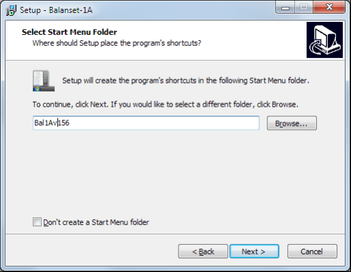
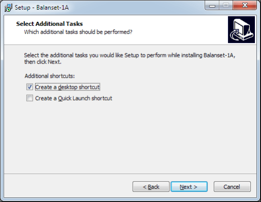
Then the program requires specifying Program group and desktop folders. Press button Next.
The window «Ready to Install» appears.
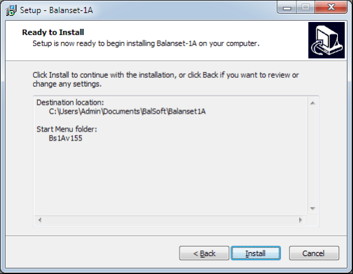
Press button «Install»

Install Arduino drivers.
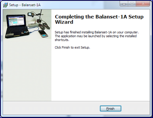
Press button “Next”, then “Install” and “Finish”
And finally press button «Finish»
As a result all necessary drivers and the balancing software are installed on the computer. After that it is possible to connect the USB interface unit to the computer.

Fig. 7.1. Initial window of the “Balanset-1A”
There are 9 buttons in the Initial window with the names of the functions realized when click on them.
Pressing “F2– Single-plane” (or F2 function key on the computer keyboard) selects the measurement vibration on thechannel X1.
After clicking this button, the computer display diagram shown in Fig. 7.1 illustrating a process of measuring the vibration only on the first measuring channel (or the balancing process in a single plane).
Pressing the “F3–Two-plane” (or F3 function key on the computer keyboard) selects the mode of vibration measurements on two channels X1 and X2 simultaneously. (Fig. 7.3.)
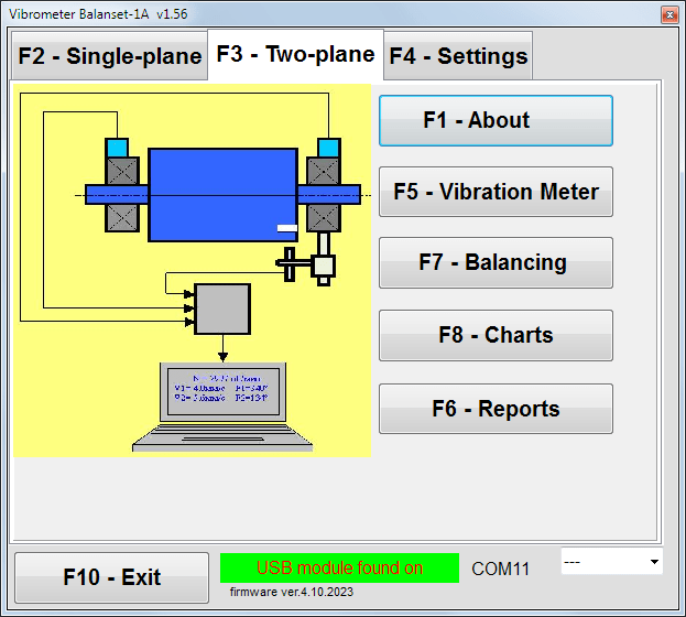
Fig. 7.3. Initial window of the “Balanset-1A”. Two plane balancing.
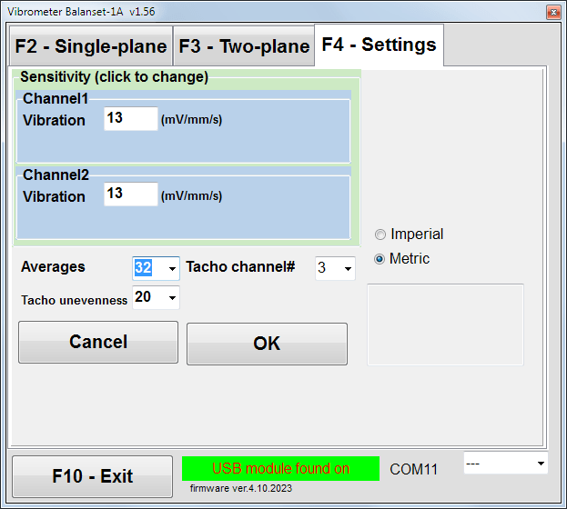
In this window you can change some Balanset-1A settings.
Fig. 7.4. “Settings” window
Changing the sensitivity coefficients of sensors is required only when replacing sensors!
Attention!
When you enter a sensitivity coefficient its fractional part is separated from the integer part with the decimal point (the sign “,”).
• Averaging – number of averaging (number of revolutions of the rotor over which data is averaged to more accuracy)
• Tacho channel# – channel# the Tacho is connected. By default – 3rd channel.
• Unevenness – the difference in duration between adjacent tacho pulses, which above gives the warning “Failure of the tachometer“
• Imperial/Metric – Select the system of units.
Com port number is assigned automatically.
Pressing this button (or a function key of F5 on the computer keyboard) activates the mode of vibration measurement on one or two measuring channels of virtual Vibration meter depending on the buttons condition “F2-single-plane”, “F3-two-plane”.
Pressing this button (or F6 function key on the computer keyboard) switches on the balancing Archive, from which you can print the report with the results of balancing for a specific mechanism (rotor).
Pressing this button (or function key F7 on your keyboard) activates balancing mode in one or two correction planes depending on which measurement mode is selected by pressing the buttons “F2-single-plane”, “F3-two-plane”.
Pressing this button (or F8 function key on the computer’s keyboard) enables graphic Vibration meter, the implementation of which displays on a display simultaneously with the digital values of the amplitude and phase of the vibration graphics of its time function.
Pressing this button (or F10 function key on the computer’s keyboard) completes the program “Balanset-1A”.
7.2. “Vibration meter”.
Before working in the “ Vibration meter ” mode, install vibration sensors on the machine and connect them respectively to the connectors X1 and X2 of the USB interface unit. Tacho sensor should be connected to the input X3 of the USB interface unit.

Fig. 7.5 USB interface unit
Place reflective type on the surface of a rotor for tacho wotking.

Fig. 7.6. Reflective type.
Recommendations for the installation and configuration of sensors are given in Annex 1.
To begin the measurement in the Vibration meter mode click on the button “F5 – Vibration Meter” in the Initial window of the program (see fig. 7.1).
Vibration Meter window appears (see. Fig.7.7)

Fig. 7.7. Vibration meter mode. Wave and Spectrum.
To start vibration measurements click button “F9 – Run” (or press the function key F9 on the keyboard).
If Trigger mode Auto is checked – the results of vibration measurements will be periodically displayed on the screen.
In case of simultaneous measurement of vibration on the first and second channels, the windows located beneath the words “Plane 1” and “Plane 2” will be filled.
Vibration measuring in the “Vibration” mode also may be carried out with disconnected phase angle sensor. In the Initial window of the program the value of the total RMS vibration (V1s, V2s) will only be displayed.
There are next settings in Vibration meter mode
To complete the work in the “Vibration meter” mode click button “F10 – Exit” and return to the Initial window.

Fig. 7.8. Vibration meter mode. Rotation speed Unevenness, 1x vibration wave form.
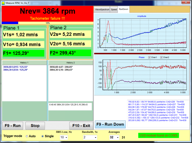
Fig. 7.9. Vibration meter mode. Rundown (beta version, no warranty!).