Mašine za balansiranje vlastitim rukama
Sveobuhvatan tehnički vodič za izgradnju profesionalne mašine za balansiranje. Saznajte više o dizajnima mekih i čvrstih ležaja, proračunima vretena, sistemima potporanja i integraciji mjerne opreme.
Sadržaj







1. Uvod
(Zašto je bilo potrebno napisati ovaj rad?)
An analysis of the consumption structure of balancing devices manufactured by LLC “Kinematics” reveals that about 30% of them are purchased for use as stationary measuring and computing systems for balancing machines and/or stands. It is possible to identify two groups of consumers (customers) of our equipment.
Prvu grupu čine preduzeća koja se specijalizuju za masovnu proizvodnju balansirnih mašina i njihovu prodaju eksternim kupcima. Ova preduzeća zapošljavaju visoko kvalifikovane specijaliste sa dubokim znanjem i opsežnim iskustvom u projektovanju, proizvodnji i upravljanju različitim vrstama balansirnih mašina. Izazovi koji nastaju u interakcijama sa ovom grupom potrošača najčešće su povezani sa prilagođavanjem naših mjernih sistema i softvera postojećim ili novorazvijenim mašinama, bez rješavanja pitanja njihove konstrukcijske izvedbe.
Drugu grupu čine potrošači koji razvijaju i proizvode mašine (stalke) za sopstvene potrebe. Ovaj pristup se uglavnom objašnjava željom nezavisnih proizvođača da smanje sopstvene troškove proizvodnje, što u nekim slučajevima može rezultirati smanjenjem za dva do tri puta ili više. Ova grupa potrošača često nema odgovarajuće iskustvo u kreiranju mašina i obično se oslanja na zdrav razum, informacije sa interneta i bilo koje dostupne analoge u svom radu.
Interakcija s njima podiže mnogo pitanja koja, uz dodatne informacije o mjernim sistemima balansirnih mašina, obuhvataju širok spektar pitanja vezanih za konstrukcijsku izvedbu mašina, metode njihove instalacije na temelj, izbor pogona i postizanje odgovarajuće tačnosti balansiranja, itd.
Imajući na umu značajno zanimanje koje je velika grupa naših konzumenata pokazala za pitanja samostalne proizvodnje mašina za balansiranje, stručnjaci iz LLC "Kinematics" (Vibromera) su pripremili kompilaciju s napomenama i preporukama o najčešće postavljenim pitanjima.
2. Vrste balansirnih mašina (stalaka) i njihove konstrukcijske karakteristike
A balancing machine is a technological device designed to eliminate the static or dynamic unbalance of rotors for various purposes. It incorporates a mechanism that accelerates the balanced rotor to a specified rotation frequency and a specialized measuring and computing system that determines the masses and placement of corrective weights required to compensate for the rotor’s imbalance.
The construction of the mechanical part of the machine typically consists of a bedframe on which support posts (bearings) are installed. These are used to mount the balanced product (rotor) and include a drive intended for rotating the rotor. During the balancing process, which is performed while the product is rotating, the measuring system’s sensors (whose type depends on the machine’s design) either register vibrations in the bearings or forces at the bearings.
Podaci dobijeni na ovaj način omogućavaju određivanje masa i lokacija instalacije korekcionih tegova neophodnih za kompenzaciju neuravnoteženosti.
Trenutno su najrasprostranjenije dvije vrste konstrukcija balansirnih mašina (stalaka):
- Mašine s mekim osloncima (s elastičnim osloncima);
- Mašine s krutim osloncima (s krutim osloncima).
2.1. Mašine i stalci s mekim ležajevima
Osnovna karakteristika balansirnih mašina (stalaka) sa mekim ležajevima (Soft Bearing) je da imaju relativno fleksibilne oslonce, izrađene na bazi opružnih ovjesa, kolica na oprugama, ravnih ili cilindričnih opružnih nosača, itd. Sopstvena frekvencija ovih oslonaca je najmanje 2-3 puta niža od frekvencije rotacije balansiranih rotora montiranih na njima. Klasičan primjer konstrukcijske izvedbe fleksibilnih oslonaca Soft Bearing može se vidjeti u nosaču mašine modela DB-50, čija je fotografija prikazana na Slici 2.1.
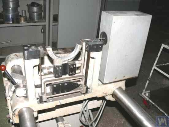
Slika 2.1. Nosač balansirne mašine modela DB-50.
Kako je prikazano na Slici 2.1, pokretni okvir (klizač) 2 pričvršćen je za fiksne stubove 1 nosača pomoću ovjesa na trakastim oprugama 3. Pod uticajem centrifugalne sile uzrokovane neuravnotežnošću rotora instaliranog na nosaču, kolica (klizač) 2 mogu vršiti horizontalne oscilacije u odnosu na fiksni stub 1, koje se mjere pomoću senzora vibracija.
Konstrukcijska izvedba ovog nosača osigurava postizanje niske sopstvene frekvencije oscilacija kolica, koja može biti oko 1-2 Hz. Ovo omogućava balansiranje rotora u širokom opsegu njegovih frekvencija rotacije, počevši od 200 RPM. Ova karakteristika, zajedno sa relativnom jednostavnošću proizvodnje takvih nosača, čini ovaj dizajn privlačnim za mnoge naše potrošače koji proizvode balansirne mašine za sopstvene potrebe različitih namjena.
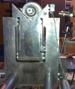
Slika 2.2. Oslonac mešnog ležaja balanserske mašine, proizvedene od strane "Polymer LTD", Mahačkala
Figure 2.2 shows a photograph of a Soft Bearing balancing machine with supports made from suspension springs, manufactured for in-house needs at “Polymer LTD” in Makhachkala. The machine is designed for balancing rollers used in the production of polymer materials.
Slika 2.3 sadrži fotografiju balansirne mašine sa sličnim trakastim ovjesom za kolica, namijenjenom za balansiranje specijalizovanih alata.
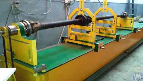
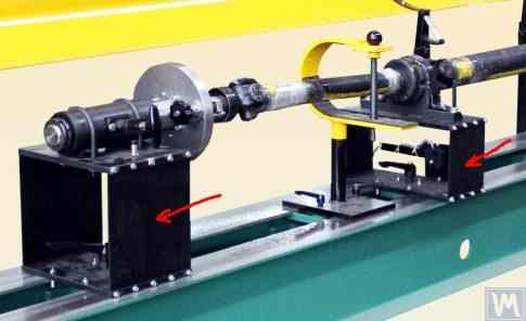
Slike 2.4.a i 2.4.b prikazuju fotografije ručno izrađene Soft Bearing mašine za balansiranje pogonskih vratila, čiji su nosači također izrađeni koristeći opruge trakastog ovjesa.
Slika 2.5 presents a photograph of a Soft Bearing machine designed for balancing turbochargers, with the supports of its carriages also suspended on strip springs. The machine, made for the private use of A. Shahgunyan (St. Petersburg), is equipped with the “Balanset 1” measuring system.
Prema proizvođaču (vidi Sl. 2.6), ova mašina omogućava balansiranje turbina sa preostalom neuravnotežnošću koja ne prelazi 0,2 g*mm.
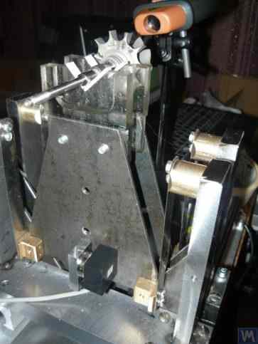
Slika 2.3. Soft Bearing mašina za balansiranje alata sa ovjesom nosača na trakastim oprugama
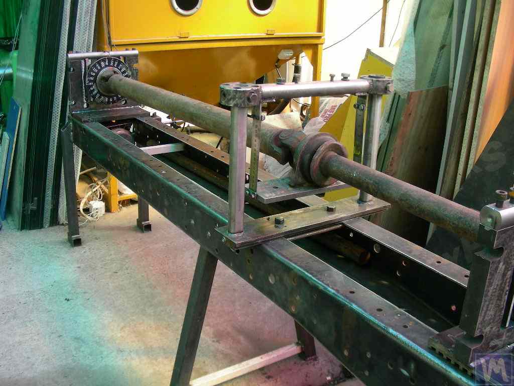
Slika 2.4.a. Soft Bearing mašina za balansiranje pogonskih vratila (mašina sastavljena)
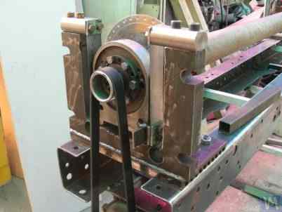
Slika 2.4.b. Soft Bearing mašina za balansiranje pogonskih vratila sa nosačima kolica ovješena na trakastim oprugama. (Vodeći nosač vretena sa ovjesom na trakastim oprugama)
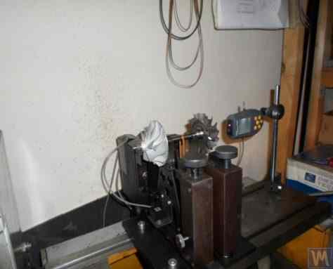
Slika 2.5. Soft Bearing mašina za balansiranje turbopunjača sa nosačima na trakastim oprugama, proizvedena od strane A. Shahgunyan (Sankt Peterburg)
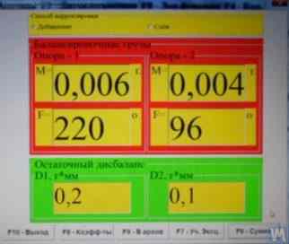
Slika 2.6. Prikazna kopija ekrana sistema za mjerenje 'Balanset 1' sa prikazanim rezultatima balansiranja rotora turbine na mašini A. Šahgunyana
Pored klasične verzije nosača balansirnih mašina sa mekim ležajevima (Soft Bearing) raspravljane iznad, postale su rasprostranjene i druge konstrukcijske izvedbe.
Slike 2.7 i 2.8 fotografije balanserskih mašina za pogonske vratile sa nosačima izrađenim na osnovu ravnih (pločastih) opruga. Te mašine su proizvedene za unutarnje potrebe privatnog preduzeća "Dergačeva" i "Tatkardan" ("Kinetika-M"), respektivno.
Soft Bearing balancing machines with such supports are often reproduced by amateur manufacturers due to their relative simplicity and manufacturability. These prototypes are generally either VBRF series machines from “K. Schenck” or similar domestic production machines.
Mašine prikazane na Slikama 2.7 i 2.8 namijenjene su za balansiranje pogonskih vratila sa dva, tri i četiri oslonca. Imaju sličnu konstrukciju, uključujući:
- zavareno postolje 1, zasnovano na dva I-nosača povezana poprečnim rebrima;
- nepokretni (prednji) oslonac vretena 2;
- pokretni (zadnji) oslonac vretena 3;
- jedan ili dva pokretna (srednja) nosača 4. Nosači 2 i 3 sadrže jedinice vretena 5 i 6, namijenjene za montažu balansiranih pogonskih vratila 7 na mašinu.
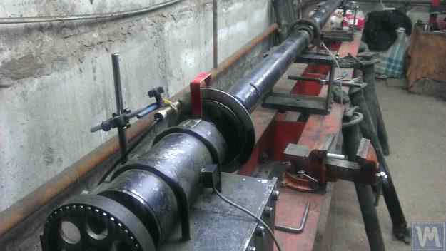
Slika 2.7. Mešna balanserska mašina za pogonska vratila privatnog preduzeća "Dergačeva" sa nosačima na ravnim (pločastim) oprugama
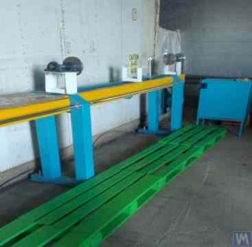
Slika 2.8. Mešna balanserska mašina za pogonska vratila "Tatkardan" ("Kinetika-M") sa nosačima na ravnim oprugama
Senzori vibracija 8 instalirani su na svim nosačima, koji se koriste za mjerenje poprečnih oscilacija nosača. Vodeće vreteno 5, montirano na nosaču 2, rotira se električnim motorom putem kaišnog pogona.
Slike 2.9.a i 2.9.b prikazuju fotografije nosača balansirne mašine, koji je zasnovan na ravnim oprugama.
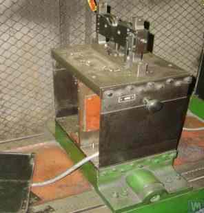
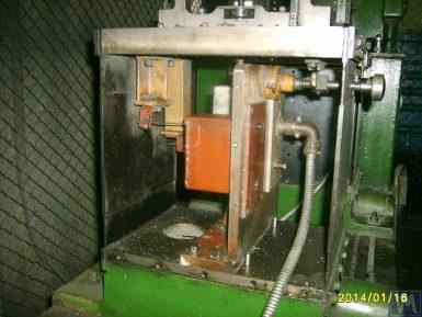
Slika 2.9. Nosač balansirne mašine sa mekim ležajevima (Soft Bearing) sa ravnim oprugama
- a) Bočni pogled;
- b) Prednji pogled
S obzirom na to da amaterski proizvođači često koriste takve nosače u svojim konstrukcijama, korisno je detaljnije ispitati karakteristike njihove izrade. Kao što je prikazano na slici 2.9.a, ovaj nosač sastoji se od tri glavne komponente:
- Donja potporna ploča 1: Za prednji nosač vretena, ploča je čvrsto pričvršćena za vodilice; za međunosače ili zadnje nosače vretena, donja ploča je konstruisana kao klizač koji se može kretati duž vodilica okvira.
- Gornja potporna ploča 2, na koje su montirani nosači (kotrljački nosači 4, vretena, međuležajevi itd.).
- Dvije plosnate opruge 3, koje povezuju donju i gornju ploču ležaja.
Kako bi se spriječio rizik od povećanja vibracija nosača tokom rada, što se može desiti tokom ubrzanja ili usporavanja balansiranih rotora, nosači mogu uključivati zaključavajući mehanizam (vidi sl. 2.9.b). Ovaj mehanizam sastoji se od čvrste konzole 5, koju može aktivirati ekscentrična brava 6 povezana sa jednom od pločastih opruga nosača. Kada su brava 6 i konzola 5 aktivirane, nosač je zaključan, čime se eliminiše rizik od povećanja vibracija tokom ubrzanja i usporavanja.
Prilikom projektovanja nosača izrađenih sa pločastim oprugama, proizvođač mašine mora procijeniti frekvenciju njihovih sopstvenih oscilacija, koja zavisi od krutosti opruga i mase balansiranih rotora. Poznavanje ovog parametra omogućava konstruktoru da svjesno odabere opseg radnih frekvencija rotacije rotora, izbjegavajući opasnost od rezonantnih oscilacija nosača tokom balansiranja.
Preporuke za izračunavanje i eksperimentalno određivanje sopstvenih frekvencija oscilacija nosača, kao i drugih komponenti balansnih mašina, razmatrane su u odjeljku 3.
Kao što je ranije napomenuto, jednostavnost i izvodljivost konstrukcije nosača korištenjem pločastih opruga privlače amaterske developere balansnih mašina za različite svrhe, uključujući mašine za balansiranje radilica, rotora turbopunjača za automobile itd.
As an example, Figures 2.10.a and 2.10.b present a general view sketch of a machine designed for balancing turbocharger rotors. This machine was manufactured and is used for in-house needs at LLC “SuraTurbo” in Penza.
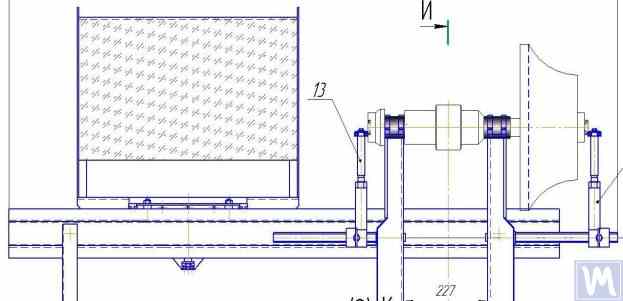
2.10.a. Mašina za balansiranje rotora turbopunjača (pogled sa strane)
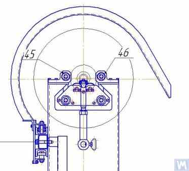
2.10.b. Mašina za balansiranje rotora turbopunjača (pogled sa strane prednjeg nosača)
Pored ranije opisanih balansnih mašina sa mekim nosačima (Soft Bearing), ponekad se prave relativno jednostavni stalci sa mekim nosačima. Ovi stalci omogućavaju visokokvalitetno balansiranje rotacionih mehanizama za različite svrhe uz minimalne troškove.
Nekoliko takvih stativa razmatrano je u nastavku, izgrađeno na osnovu ravne pločaste osnove (ili rama) postavljene na valjkaste opruge sa sabijanjem. Te opruge se obično biraju tako da je prirodna frekvencija oscilacija pločaste osnove sa instaliranim balanserskim mehanizmom 2 do 3 puta niža od frekvencije rotacije rotora tog mehanizma tijekom balansiranja.
Slika 2.11 prikazuje fotografiju stalca za balansiranje brusnih diskova, proizvedenog za interne potrebe od strane P. Ašarina.
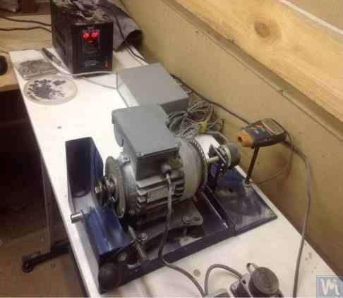
Slika 2.11. Postolje za balansiranje abrazivnih ploča
Stalak se sastoji od sljedećih glavnih komponenti:
- Ploča 1, postavljena na četiri cilindrične opruge 2;
- Elektromotor 3, čiji rotor istovremeno služi kao vreteno, na koje je montiran trn 4, koji se koristi za postavljanje i pričvršćivanje brusnog diska na vreteno.
A key feature of this stand is the inclusion of a pulse sensor 5 for the rotational angle of the electric motor’s rotor, which is used as part of the measuring system of the stand (“Balanset 2C”) to determine the angular position for removing the corrective mass from the abrasive wheel.
Slika 2.12 prikazuje fotografiju stativa koji se koristi za balansiranje vakuumskih pumpi. Taj stativ je razvijen na narudžbu od strane akcionarskog društva "Mjerilo Fabrika".
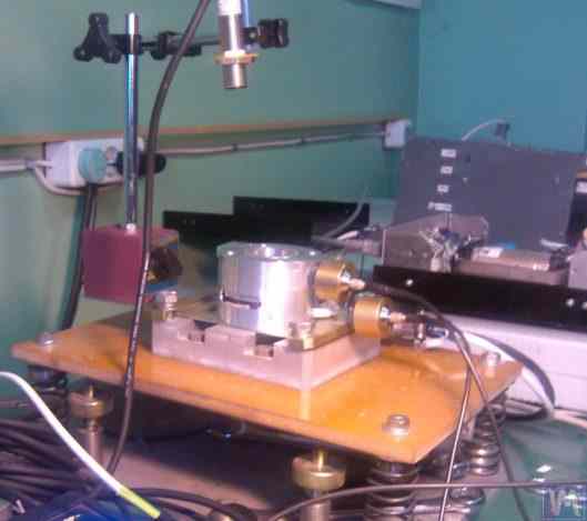
Slika 2.12. Stativ za balansiranje vakuumskih pumpi od strane akcionarskog društva "Mjerilo Fabrika"
Osnova ovog stalka također koristi Ploča 1, montirana na cilindrične opruge 2. Na ploču 1 instalirana je vakuumska pumpa 3, koja ima vlastiti električni pogon sposoban za široko variranje brzina od 0 do 60.000 RPM. Senzori vibracija 4 montirani su na kućište pumpe, koji se koriste za mjerenje vibracija u dva različita presjeka na različitim visinama.
For synchronization of the vibration measurement process with the rotational angle of the pump rotor, a laser phase angle sensor 5 is used on the stand. Despite the seemingly simplistic external construction of such stands, it allows achieving very high-quality balancing of the pump’s impeller.
Na primjer, pri podkritičnim brzinama obrtanja, preostala neuravnoteženost rotora pumpe je ispod tolerancije najfinijeg razreda kvaliteta balansiranja definiranog u ISO 21940-11 (ranije ISO 1940-1), G0.4 — interni rezultat na stalku je ekvivalentan uslovnom G0.16, što je strože od bilo kojeg razreda navedenog u standardu.
Preostale vibracije kućišta pumpe postignute tokom balansiranja pri radnim brzinama do 8.000 RPM ne prelaze 0,01 mm/s.
Stalci za balansiranje proizvedeni prema gore opisanom shemi također su efikasni pri balansiranju drugih mehanizama, kao što su ventilatori. Primjeri stalaka dizajniranih za balansiranje ventilatora prikazani su na slikama 2.13 i 2.14.
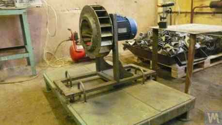
Slika 2.13. Postolje za balansiranje rotora ventilatora
Kvaliteta balansiranja ventilatora postignuta na takvim stativima je dovoljno visoka. Prema specijalistima iz "Atlant-projekt" doo, na stativu koji su oni dizajnirali na osnovu preporuka "Kinematika" doo (vidi sl. 2.14), nivo rezidualnih vibracija postignute pri balansiranju ventilatora bio je 0,8 mm/s. To je više od tri puta bolje od tolerancije postavljene za ventilatore u kategoriji BV5 prema ISO 31350-2007 "Vibracija. Industrijski ventilatori. Zahtjevi za proizvedenu vibraciju i kvalitetu balansa."
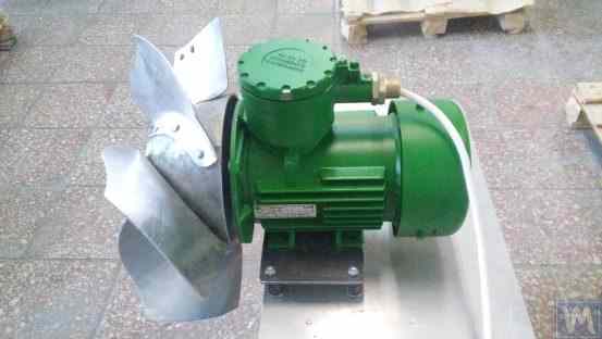
Slika 2.14. Stativ za balansiranje lopatica ventilatora eksplozivno sigurne opreme od strane "Atlant-projekt" doo, Podolsk
Similar data obtained at JSC “Lissant Fan Factory” show that such stands, used in the serial production of duct fans, consistently ensured a residual vibration not exceeding 0.1 mm/s.
2.2. Mašine s krutim osloncima
Balansne mašine sa čvrstim nosačima (Hard Bearing) razlikuju se od ranije opisanih mašina sa mekim nosačima (Soft Bearing) po konstrukciji njihovih nosača. Njihovi nosači su izrađeni u obliku čvrstih ploča sa složenim utorima (izrezima). Sopstvene frekvencije ovih nosača značajno (najmanje 2-3 puta) premašuju maksimalnu frekvenciju rotacije rotora balansiranih na mašini.
Mašine sa čvrstim nosačima su svestranije od onih sa mekim nosačima, jer obično omogućavaju visokokvalitetno balansiranje rotora u širem opsegu njihovih masenih i dimenzionalnih karakteristika. Važna prednost ovih mašina je i to da omogućavaju precizno balansiranje rotora pri relativno niskim radnim brzinama, koje mogu biti u opsegu od 200-500 RPM i niže.
Slika 2.15 shows a photograph of a typical Hard Bearing balancing machine manufactured by “K. Schenk.” From this figure, it is evident that individual parts of the support, formed by the intricate slots, have varying stiffness. Under the influence of the forces of rotor unbalance, this can lead to deformations (displacements) of some parts of the support relative to others. (In Figure 2.15, the stiffer part of the support is highlighted with a red dotted line, and its relatively compliant part is in blue).
Za mjerenje navedenih relativnih deformacija, mašine sa čvrstim nosačima mogu koristiti ili senzore sile ili visoko osjetljive senzore vibracija različitih tipova, uključujući beskontaktne senzore pomjeranja vibracija.
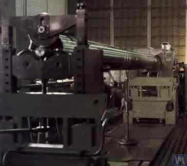
Slika 2.15. Kruta mašina za balansiranje od strane "K. Schenk"
As indicated by the analysis of requests received from customers for the “Balanset” series instruments, interest in manufacturing Hard Bearing machines for in-house use has been continuously increasing. This is facilitated by the widespread dissemination of advertising information about the design features of domestic balancing machines, which are used by amateur manufacturers as analogs (or prototypes) for their own developments.
Razmotrimo neke varijacije mašina sa krutim ležajima proizvedenih za unutarnje potrebe broja potrošača instrumenata serije "Balanset".
Slike 2.16.a – 2.16.d show photographs of a Hard Bearing machine designed for balancing drive shafts, which was manufactured by N. Obyedkov (city of Magnitogorsk). As seen in Fig. 2.16.a, the machine consists of a rigid frame 1, on which supports 2 (two spindle and two intermediate) are installed. The main spindle 3 of the machine is rotated by an asynchronous electric motor 4 via a belt drive. A frequency controller 6 is used to control the rotation speed of the electric motor 4. The machine is equipped with the “Balanset 4” measuring and computing system 5, which includes a measuring unit, a computer, four force sensors, and a phase angle sensor (sensors not shown in Fig. 2.16.a).
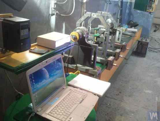
Slika 2.16.a. Mašina sa čvrstim nosačima za balansiranje pogonskih vratila, proizvedena od strane N. Objedkova (Magnitogorsk)
Slika 2.16.b prikazuje fotografiju prednjeg nosača mašine sa pogonskim vretenom 3, koje se, kao što je ranije napomenuto, pokreće kaišnim pogonom iz asinhronog električnog motora 4. Ovaj nosač je čvrsto montiran na okvir.
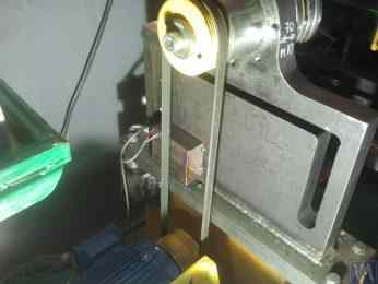
Slika 2.16.b. Prednji (vodeći) oslonac vretena.
Slika 2.16.c prikazuje fotografiju jednog od dva pokretna međunosača mašine. Ovaj nosač se oslanja na klizače 7, što omogućava njegovo longitudinalno kretanje duž vodilica okvira. Ovaj nosač uključuje specijalni uređaj 8, dizajniran za postavljanje i podešavanje visine međuležaja balansiranih pogonskih vratila.
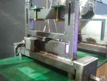
Slika 2.16.c. Pokretni međunosač mašine
Slika 2.16.d shows a photograph of the rear (driven) spindle support, which, like the intermediate supports, allows for movement along the machine frame’s guides.
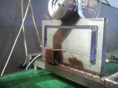
Slika 2.16.d. Zadnji (pogonjeni) oslonac vretena.
Svi gore opisani nosači su vertikalne ploče montirane na ravne baze. Ploče imaju T-utor (vidi sl. 2.16.d), koji dijeli nosač na unutrašnji dio 9 (krutiji) i vanjski dio 10 (manje krut). Različita krutost unutrašnjeg i vanjskog dijela nosača može rezultirati relativnom deformacijom ovih dijelova pod silama neuravnoteženosti balansiranih rotora.
Senzori sile se obično koriste za mjerenje relativne deformacije nosača u mašinama domaće izrade. Primjer kako se senzor sile instalira na nosač balansne mašine sa čvrstim nosačima (Hard Bearing) prikazan je na slici 2.16.e. Kao što se vidi na ovoj slici, senzor sile 11 je pritisnut uz bočnu površinu unutrašnjeg dijela nosača pomoću vijka 12, koji prolazi kroz navojnu rupu u vanjskom dijelu nosača.
Kako bi se osigurao ravnomjeran pritisak vijka 12 na cijeloj ravni senzora sile 11, između njega i senzora postavljena je ravna podloška 13.
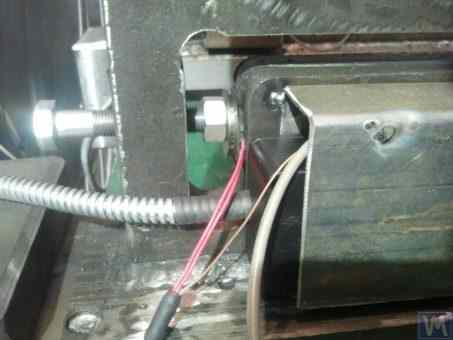
Slika 2.16.d. Primjer instalacije senzora sile na nosač.
During the operation of the machine, the forces of imbalance from the balanced rotor act through the support units (spindles or intermediate bearings) on the outer part of the support, which begins to cyclically move (deform) relative to its inner part at the frequency of rotor rotation. This results in a variable force acting on sensor 11, proportional to the imbalance force. Under its influence, an electrical signal proportional to the magnitude of the rotor’s imbalance is generated at the output of the force sensor.
Signals from force sensors, installed on all supports, are fed into the machine’s measuring and computing system, where they are used to determine the parameters of the corrective weights.
Slika 2.17.a. prikazuje fotografiju visoko specijalizovane krute balanserske mašine koja se koristi za balansiranje "pužnih" vratila. Ta mašina je proizvedena za unutarnju upotrebu kod "Ufatverdosplava" doo.
Kao što se vidi na slici, mehanizam ubrzanja mašine ima pojednostavljenu konstrukciju, koja se sastoji od sljedećih glavnih komponenti:
- Zavareni okvir 1, koji služi kao postolje;
- Dva nepokretna oslonca 2, kruto pričvršćen na okvir;
- Elektromotor 3, koji pokreće balansirano vreteno (vijak) 5 putem kaišnog pogona 4.
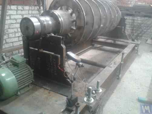
Slika 2.17.a. Kruta mašina za balansiranje pužnih vratila, proizvedena od strane "Ufatverdosplava" doo
Nosači 2 mašine su vertikalno instalirane čelične ploče sa T-utorima. Na vrhu svakog nosača nalaze se potporni valjci izrađeni korištenjem kotrljajućih ležajeva, na kojima se rotira balansirano vratilo 5.
To measure the deformation of the supports, which occurs under the action of rotor imbalance, force sensors 6 are used (see Fig. 2.17.b), which are installed in the slots of the supports. These sensors are connected to the “Balanset 1” device, which is used on this machine as a measuring and computing system.
Despite the relative simplicity of the machine’s spin-up mechanism, it enables sufficiently high-quality balancing of screws, which, as seen in Fig. 2.17.a., have a complex helical surface.
Prema "Ufatverdosplava" doo, početna neuravnoteženost pužnog vratila je smanjena za gotovo 50 puta na toj mašini tokom procesa balansiranja.
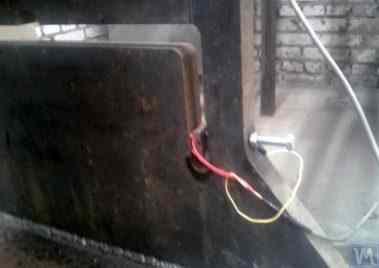
Slika 2.17.b. Nosač mašine sa čvrstim nosačima za balansiranje vijčanih vretena sa senzorom sile
Postignuta preostala neuravnoteženost iznosila je 3552 g*mm (19,2 g na radijusu od 185 mm) u prvoj ravni pužnog vratila, i 2220 g*mm (12,0 g na radijusu od 185 mm) u drugoj ravni. Za rotor mase 500 kg koji radi pri brzini obrtanja od 3500 o/min, ova neuravnoteženost odgovara razredu G6,3 prema ISO 21940-11 (ranije ISO 1940-1), što ispunjava zahtjeve navedene u njegovoj tehničkoj dokumentaciji.
An original design (see Fig. 2.18), which involves using a single base for simultaneous installation of supports for two Hard Bearing balancing machines of different sizes, was proposed by S.V. Morozov. The obvious advantages of this technical solution, which allow minimizing the manufacturer’s production costs, include:
- Ušteda proizvodnog prostora;
- Korištenje jednog električnog motora sa frekventnim regulatorom za rad dviju različitih mašina;
- Korištenje jednog mjernog sistema za rad dviju različitih mašina.

Slika 2.18. Kruta mašina za balansiranje ("Tandem"), proizvedena od strane S.V. Morozova
3. Zahtjevi za konstrukciju osnovnih jedinica i mehanizama balansirnih mašina
3.1. Ležajevi
3.1.1. Teorijske osnove konstrukcije oslonaca
In the previous section, the main design executions of Soft Bearing and Hard Bearing supports for balancing machines were discussed in detail. A crucial parameter that designers must consider when designing and manufacturing these supports is their natural frequencies of oscillation. This is important because the measurement of not only the amplitude of vibration (cyclic deformation) of the supports but also the phase of vibration is required for calculating the parameters of corrective weights by the machine’s measuring and computing systems.
If the natural frequency of a support coincides with the rotation frequency of the balanced rotor (support resonance), accurate measurement of amplitude and phase of vibration is practically impossible. This is clearly illustrated in the graphs showing changes in amplitude and phase of the support’s oscillations as a function of the rotational frequency of the balanced rotor (see Fig. 3.1).
Iz ovih grafikona slijedi da kako se rotacijska frekvencija balansiranog rotora približava vlastitoj frekvenciji oscilacija nosača (tj. kada je omjer fp/fo blizu 1), dolazi do značajnog povećanja amplitude povezanog s rezonancijom oscilacija nosača (vidi Sl. 3.1.a). Istovremeno, grafikon 3.1.b pokazuje da u rezonantnoj zoni dolazi do nagle promjene faznog ugla ∆F°, koji može doseći do 180°.
Drugim riječima, pri balansiranju bilo kojeg mehanizma u rezonantnoj zoni, čak i male promjene u njegovoj frekvenciji rotacije mogu dovesti do značajne nestabilnosti u rezultatima mjerenja amplitude i faze njegovih vibracija, što dovodi do grešaka u izračunavanju parametara korekcijskih tegova i negativno utječe na kvalitetu balansiranja.
The above graphs confirm earlier recommendations that for Hard Bearing machines, the upper limit of the rotor’s operational frequencies should be (at least) 2-3 times lower than the natural frequency of the support, fo. For Soft Bearing machines, the lower limit of permissible operational frequencies of the balanced rotor should (at least) be 2-3 times higher than the natural frequency of the support.
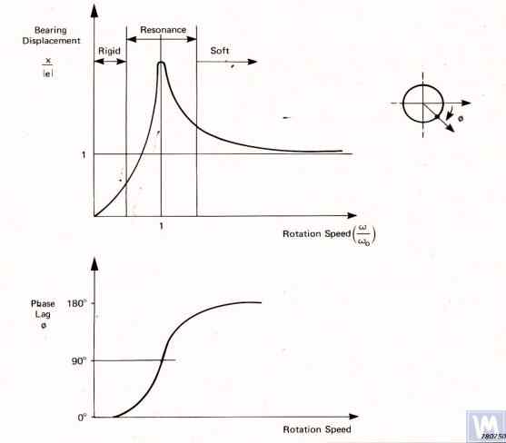
Slika 3.1. Grafikoni koji pokazuju promjene relativne amplitude i faze vibracija nosača balansirne mašine kao funkciju promjena rotacijske frekvencije.
- Ад – Amplituda dinamičkih vibracija oslonca;
- e = m*r / M - Specifična neuravnoteženost balanserskog rotora;
- m – Neuravnotežena masa rotora;
- M – Masa rotora;
- r – Polumjer na kojem se nalazi neuravnotežena masa na rotoru;
- fp – Frekvencija rotacije rotora;
- fo – Sopstvena frekvencija vibracija oslonca
S obzirom na prikazane informacije, rad mašine u rezonantnom području njenih nosača (označeno crvenom bojom na Sl. 3.1) nije preporučljiv. Grafikoni prikazani na Sl. 3.1 također demonstriraju da za iste neuravnoteženosti rotora, stvarne vibracije nosača mašina s mekim ležajevima (Soft Bearing) su značajno niže od onih koje se javljaju na nosačima mašina s mekim ležajevima.
Iz toga slijedi da senzori korišteni za mjerenje vibracija nosača u mašinama s tvrdim ležajevima (Hard Bearing) moraju imati veću osjetljivost od onih u mašinama s mekim ležajevima. Ovaj zaključak dobro je podržan stvarnom praksom korištenja senzora, koja pokazuje da apsolutni senzori vibracija (vibro-akcelerometri i/ili senzori brzine vibracija), uspješno korišteni u balansirnim mašinama s mekim ležajevima, često ne mogu postići potrebnu kvalitetu balansiranja na mašinama s tvrdim ležajevima.
Na ovim mašinama preporučuje se korištenje relativnih senzora vibracija, poput senzora sile ili visoko osjetljivih senzora pomaka.
3.1.2. Procjena vlastitih frekvencija nosača korištenjem računskih metoda
Konstruktor može izvršiti približan (procjenski) proračun vlastite frekvencije nosača fo koristeći formulu 3.1, pojednostavljeno ga tretirajući kao vibracioni sistem sa jednim stepenom slobode, koji (vidi Sl. 2.19.a) predstavlja masa M, koja oscilira na opruzi krutosti K.
Masa M korištena u izračunu za simetrični rotor između ležajeva može se aproksimirati formulom 3.2.
gdje je Mo masa pokretnog dijela oslonca u kg; Mr je masa balansirane rotora u kg; n je broj oslonaca mašine uključenih u balansiranje.
Krutost K oslonca izračunava se po formuli 3.3 na osnovu rezultata eksperimentalnih ispitivanja koja uključuju mjerenje deformacije ΔL oslonca kada se optereti statičkom silom P (vidi sl. 3.2.a i 3.2.b).
gdje je ΔL deformacija oslonca u metrima; P je statička sila u Njutnima.
Veličina sile opterećenja P može se izmjeriti instrumentom za mjerenje sile (npr. dinamometrom). Pomak oslonca ΔL određuje se uređajem za mjerenje linearnih pomaka (npr. mjernim satom).
3.1.3. Eksperimentalne metode za određivanje vlastitih frekvencija nosača
Given that the above-discussed calculation of natural frequencies of supports, performed using a simplified method, can lead to significant errors, most amateur developers prefer to determine these parameters by experimental methods. For this, they utilize capabilities provided by modern vibration measuring systems of balancing machines, including the “Balanset” series instruments.
3.1.3.1. Određivanje vlastitih frekvencija nosača metodom udarnog uzbuđivanja
Metoda udarnog uzbuđenja je najjednostavniji i najčešći način za određivanje vlastite frekvencije vibracija nosača ili bilo koje druge komponente mašine. Temelji se na činjenici da kada se bilo koji objekt, poput zvona (vidi Sl. 3.3), udarno uzbuđuje, njegov odziv se manifestuje kao postepeno prigušeni vibracijski odziv. Frekvencija vibracijskog signala određena je strukturnim karakteristikama objekta i odgovara frekvenciji njegovih vlastitih vibracija. Za udarno uzbuđenje vibracija može se koristiti bilo koji težak alat, poput gumenog čekića ili običnog čekića.
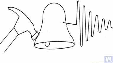
Slika 3.3. Dijagram udarnog uzbuđivanja korištenog za određivanje vlastitih frekvencija objekta
Masa čekića treba biti približno 10% mase objekta koji se uzbuđuje. Za hvatanje vibracijskog odziva, senzor vibracija treba biti instaliran na objektu koji se ispituje, pri čemu je njegova mjerna osa poravnata sa smjerom udarnog uzbuđenja. U nekim slučajevima, mikrofon iz uređaja za mjerenje buke može se koristiti kao senzor za percepciju vibracijskog odziva objekta.
The vibrations of the object are converted into an electrical signal by the sensor, which is then sent to a measuring instrument, such as the input of a spectrum analyzer. This instrument records the time function and the spectrum of the decaying vibrational process (see Fig. 3.4), analysis of which allows determining the frequency (frequencies) of the object’s natural vibrations.

Slika 3.5. Korisničko sučelje programa koje prikazuje grafikone vremenske funkcije i spektar prigušenih udarnih vibracija ispitivane strukture
Analiza spektralnog grafikona prikazanog na Slici 3.5 (vidi donji dio radnog prozora) pokazuje da glavna komponenta vlastitih vibracija ispitivane strukture, određena u odnosu na apscisnu os grafikona, javlja se na frekvenciji od 9.5 Hz. Ova metoda može se preporučiti za istraživanje vlastitih vibracija nosača balansirnih mašina sa mekim ležajevima (Soft Bearing) i tvrdim ležajevima (Hard Bearing).
3.1.3.2. Određivanje vlastitih frekvencija nosača u režimu zaustavljanja po inerciji
In some cases, the natural frequencies of supports can be determined by cyclically measuring the amplitude and phase of vibration “on the coast.” In implementing this method, the rotor installed on the examined machine is initially accelerated to its maximum rotation speed, after which its drive is disconnected, and the frequency of the disturbing force associated with the rotor’s imbalance gradually decreases from maximum to the point of stop.
U ovom slučaju, vlastite frekvencije nosača mogu se odrediti po dvije karakteristike:
- Po lokalnom skoku amplitude vibracija opaženom u rezonantnim područjima;
- Po nagloj promjeni (do 180°) faze vibracija opaženoj u zoni skoka amplitude.
U uređajima serije "Balanset", mod "Vibrometar" ("Balanset 1") ili mod "Balansiranje. Nadzor" ("Balanset 2C" i "Balanset 4") može se koristiti za detektovanje prirodnih frekvencija objekata "na beregi," omogućavajući ciklička mjerenja amplitude i faze vibracija na frekvenciji rotacije rotora.
Štaviše, software "Balanset 1" dodatno sadrži specijalizovani mod "Grafici. Bereg", koji omogućava crtanje grafika promjena amplitude i faze vibracija oslonaca na beregu kao funkcije promjenjive frekvencije rotacije, što značajno olakšava proces dijagnostikovanja rezonancija.
Treba napomenuti da, iz očiglednih razloga (vidi odjeljak 3.1.1), metoda identifikacije vlastitih frekvencija nosača tokom zaustavljanja po inerciji može se koristiti samo u slučaju istraživanja balansirnih mašina sa mekim ležajevima (Soft Bearing), gdje radne frekvencije rotacije rotora značajno premašuju vlastite frekvencije nosača u poprečnom smjeru.
U slučaju mašina sa tvrdim ležajevima (Hard Bearing), gdje su radne frekvencije rotacije rotora koje uzbuđuju vibracije nosača tokom zaustavljanja po inerciji značajno ispod vlastitih frekvencija nosača, korištenje ove metode je praktično nemoguće.
3.1.4. Praktične preporuke za projektovanje i izradu nosača za balansirne mašine
3.1.2. Računanje vlastitih frekvencija nosača računskim metodama
Izračuni vlastitih frekvencija nosača korištenjem gore navedene računske sheme mogu se izvršiti u dva smjera:
- U poprečnom smjeru nosača, koji se poklapa sa smjerom mjerenja njihovih vibracija uzrokovanih silama neuravnoteženosti rotora;
- U aksijalnom smjeru, koji se poklapa sa osom rotacije balansiranog rotora montiranog na nosače mašine.
Calculating the natural frequencies of supports in the vertical direction requires the use of a more complex calculation technique, which (in addition to the parameters of the support and balanced rotor itself) must take into account the parameters of the frame and the specifics of the machine’s installation on the foundation. This method is not discussed in this publication. Analysis of formula 3.1 allows for some simple recommendations that should be considered by machine designers in their practical activities. In particular, the natural frequency of a support can be altered by changing its stiffness and/or mass. Increasing the stiffness increases the natural frequency of the support, while increasing the mass decreases it. These changes have a non-linear, square-inverse relationship. For example, doubling the stiffness of the support increases its natural frequency only by a factor of 1.4. Similarly, doubling the mass of the moving part of the support reduces its natural frequency only by a factor of 1.4.
3.1.4.1. Mašine sa mekim ležajevima sa ravnim pločastim oprugama
Several design variations of balancing machine supports made with flat springs have been discussed above in section 2.1 and illustrated in Figures 2.7 – 2.9. According to our information, such designs are most commonly used in machines intended for balancing drive shafts.
As an example, let’s consider the spring parameters used by one of the clients (LLC “Rost-Service”, St. Petersburg) in the manufacturing of their own machine supports. This machine was intended for balancing 2, 3, and 4-support drive shafts, with a mass not exceeding 200 kg. The geometric dimensions of the springs (height * width * thickness) used in the supports of the leading and driven spindles of the machine, chosen by the client, were respectively 300
The natural frequency of the unloaded support, determined experimentally by the impact excitation method using the standard measuring system of the “Balanset 4” machine, was found to be 11 – 12 Hz. At such a natural frequency of vibrations of the supports, the recommended rotational frequency of the balanced rotor during balancing should not be lower than 22-24 Hz (1320 – 1440 RPM).
Geometrijske dimenzije ravnih opruga koje isti proizvođač koristi na međuosloncima bile su redom 200*200*3 mm. Štaviše, kako su studije pokazale, prirodne frekvencije ovih oslonaca bile su veće, dosežući 13-14 Hz.
Based on the test results, the manufacturers of the machine were advised to align (equalize) the natural frequencies of the spindle and intermediate supports. This should facilitate the selection of the range of operational rotational frequencies of the drive shafts during balancing and avoid potential instabilities of the measuring system’s readings due to the supports entering the area of resonant vibrations.
Metode za podešavanje vlastitih frekvencija vibracija podupiranja na ravnim oprugama su očigledne. Ovo podešavanje može se postići promjenom geometrijskih dimenzija ili oblika ravnih opruga, što se postiže, na primjer, glodanjem uzdužnih ili poprečnih utora koji smanjuju njihovu krutost.
Kako je ranije spomenuto, verifikacija rezultata takvog podešavanja može se provesti identificiranjem sopstvenih frekvencija vibracija podupiranja korištenjem metoda opisanih u odjeljcima 3.1.3.1 i 3.1.3.2.
Slika 3.6 predstavlja klasičnu verziju dizajna podupiranja na ravnim oprugama, korištenu u jednoj od njegovih mašina od strane A. Sinitsyna. Kako je prikazano na slici, podupiranje uključuje sljedeće komponente:
- Gornja ploča 1;
- Dvije plosnate opruge 2 i 3;
- Donja ploča 4;
- Graničnik 5.
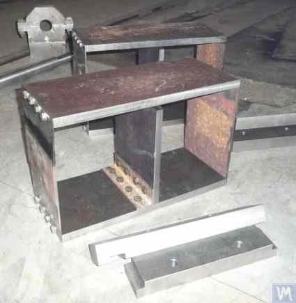
Slika 3.6. Varijanta dizajna podupiranja na ravnim oprugama
Gornja ploča 1 podupiranja može se koristiti za montažu vretena ili međuležaja. U zavisnosti od namjene podupiranja, donja ploča 4 može biti čvrsto pričvršćena za vodilice mašine ili instalirana na pokretnim klizačima, omogućavajući podupiranju da se kreće duž vodilica. Nosač 5 se koristi za instaliranje zaključavajućeg mehanizma za podupiranje, omogućavajući mu da bude sigurno fiksiran tokom ubrzanja i usporavanja balansiranog rotora.
Flat springs for Soft Bearing machine supports should be made from leaf-spring or high-quality alloyed steel. The use of ordinary structural steels with a low yield strength is not advisable, as they may develop residual deformation under static and dynamic loads during operation, leading to a reduction in the machine’s geometric accuracy and even to the loss of support stability.
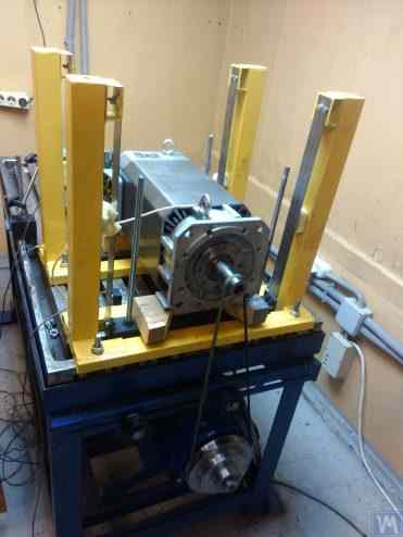
Slika 3.7. Mašina za balansiranje rotora električnih motora, sastavljena, razvijena od strane A. Mokhova.
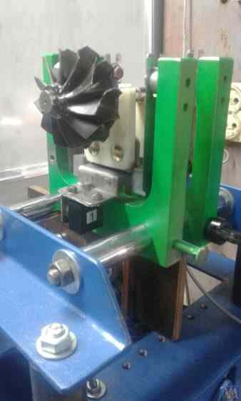
Slika 3.8. Mašina za balansiranje rotora turbopumpa, razvijena od strane G. Glazova (Biškek)
3.1.4.2. Podupiranja mašina sa mekim ležajevima sa ovjesom na trakastim oprugama
Pri projektiranju trakastih opruga korištenih za podupiranje ovjesa, pažnja treba biti posvećena odabiru debljine i širine trake opruge, koja s jedne strane mora izdržati statičko i dinamičko opterećenje rotora na podupiranju, a s druge strane, mora spriječiti mogućnost torzijskih vibracija ovjesa podupiranja, koje se manifestuju kao aksijalno bacanje.
Examples of structural implementation of balancing machines using strip spring suspensions are shown in Figures 2.1 – 2.5 (see section 2.1), as well as in Figures 3.7 and 3.8 of this section.
3.1.4.4. Kruti oslonci sa kuglicama za mašine
Kao što pokazuje naše extensive iskustvo sa klijentima, značajan dio proizvođača samonapravljenih balansera nedavno je počeo preferirati mašine sa krutim osloncima sa kuglicama. U sekciji 2.2, slike 2.16 – 2.18 prikazuju fotografije raznih konstrukcijskih dizajna mašina sa takvim osloncima. Tipična skica krutog oslonca, razvijena od strane jednog od naših klijenata za njihovu konstrukciju mašine, prikazana je na slici 3.10. Ovaj oslonac se sastoji od ravne čelične ploče sa P-oblikovanim žljebom, koji konvencionalno dijeli oslonac na "krute" i "fleksibilne" dijelove. Pod utjecajem sile nebalansirage, "fleksibilni" dio oslonca može se deformirati u odnosu na njegov "kruti" dio. Veličina ove deformacije, određena debljinom oslonca, dubinom žljeba i širinom mosta koji povezuje "fleksibilne" i "krute" dijelove oslonca, može se mjeriti pomoću odgovarajućih senzora mjernog sistema mašine. Zbog nedostatka metode za izračunavanje poprečne krutosti takvih oslonaca, vodeći računa o dubini h P-oblikovanog žljeba, širini t mosta, kao i debljini oslonca r (vidi sliku 3.10), ovi parametri dizajna obično se određuju eksperimentalno od strane razvijatelja.
Za mašine sa masom balansirane rotora koja ne prelazi 300 - 500 kg, debljina oslonca može se povećati na 30 – 40 mm, a za mašine dizajnirane za balansiranje rotora sa maksimalnim masama u rasponu od 1000 do 3000 kg, debljina oslonca može dosegnuti 50 – 60 mm ili više. Kako analiza dinamičkih karakteristika gore navedenih oslonaca pokazuje, njihove prirodne frekvencije vibracija, mjerene u poprečnoj ravnini (ravnina mjerenja relativnih deformacija "fleksibilnih" i "krutih" dijelova), obično prelaze 100 Hz ili više. Prirodne frekvencije vibracija oslonaca sa krutim kuglicama na čeonoj ravnini, mjerene u smjeru koji se podudara sa osom rotacije balansirane rotora, obično su značajno niže. I upravo su ove frekvencije ones koje trebaju biti primarno uzete u obzir pri određivanju gornje granice radnog frekventnog opsega za rotirajuće rotore balansirane na mašini.
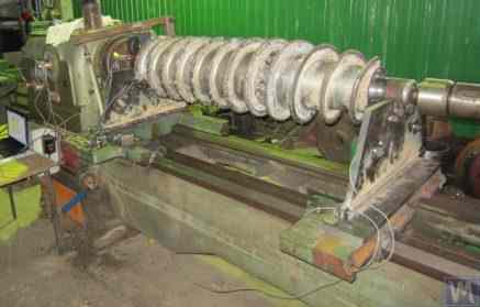
Slika 3.26. Primjer korištenja rabljenog postolja struga za izradu mašine s krutim ležajevima za balansiranje vijkova.
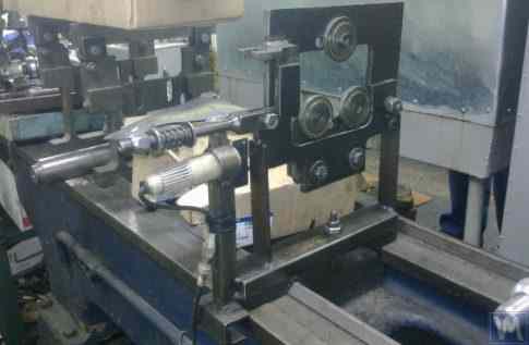
Slika 3.27. Primjer korištenja rabljenog postolja struga za izradu mašine s mekim ležajevima za balansiranje vratila.
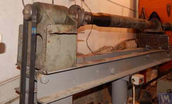
Slika 3.28. Primjer izrade sklopnog postolja od profila
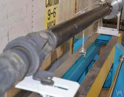
Slika 3.29. Primjer izrade zavarenog postolja od profila
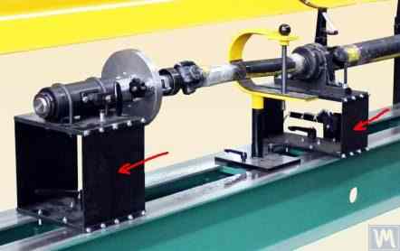
Slika 3.30. Primjer izrade zavarenog postolja od profila
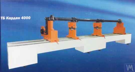
Slika 3.31. Primjer postolja balansne mašine izrađenog od polimernog betona
Obično, pri proizvodnji takvih postolja, njihov gornji dio je ojačan čeličnim umetcima koji se koriste kao vodiče na koje se oslanjaju oslonci postolja balansne mašine. U posljednje vrijeme, postolja su izrađena od polimerbetona sa vibracijski prigušavajućim premazima postala široko korišćena. Ova tehnologija za proizvodnju postolja je dobro opisana na internetu i može se lako implementirati od strane DIY proizvođača. Zbog relativne jednostavnosti i niske cijene proizvodnje, ova postolja imaju nekoliko ključnih prednosti u odnosu na svoje metalne parnjake:
- Veći koeficijent prigušenja za vibracijske oscilacije;
- Niža toplinska vodljivost, što osigurava minimalnu toplinsku deformaciju postolja;
- Veća otpornost na koroziju;
- Odsustvo unutrašnjih naprezanja.
3.1.4.3. Podupiranja mašina sa mekim ležajevima izrađena korištenjem cilindričnih opruga
Primjer mašine za balansiranje s mekim osloncima, kod koje se u konstrukciji oslonaca koriste cilindrične tlačne opruge, prikazan je na slici 3.9. Glavni nedostatak ovog konstruktivnog rješenja povezan je s različitim stepenom deformacije opruga na prednjem i zadnjem osloncu, koja nastaje ako su opterećenja oslonaca nejednaka pri balansiranju asimetričnih rotora. To prirodno dovodi do neusklađenosti oslonaca i iskošenja ose rotora u vertikalnoj ravni. Jedna od negativnih posljedica ovog nedostatka može biti pojava sila koje uzrokuju aksijalno pomjeranje rotora tokom rotacije.
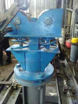
Sl. 3.9. Varijanta konstrukcije podupiranja sa mekim ležajevima za mašine za balansiranje korištenjem cilindričnih opruga.
3.1.4.4. Kruti oslonci sa kuglicama za mašine
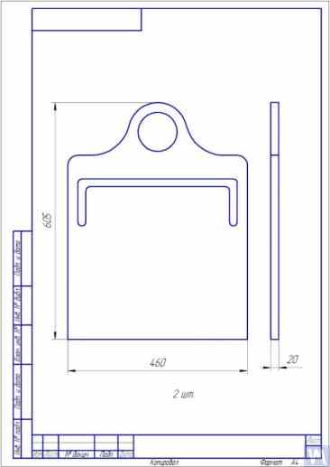
Sl. 3.10. Skica podupiranja sa tvrdim ležajevima za mašinu za balansiranje
Photographs displaying various implementations of such supports, manufactured for our clients’ own machines, are presented in Figures 3.11 and 3.12. Summarizing the data obtained from several of our clients who are machine manufacturers, requirements for the thickness of supports, set for machines of various sizes and load capacities, can be formulated. For example, for machines intended to balance rotors weighing from 0.1 to 50-100 kg, the thickness of the support may be 20 mm.
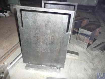
Sl. 3.11. Podupiranja sa tvrdim ležajevima za mašinu za balansiranje, proizvedena od strane A. Sinitsyna
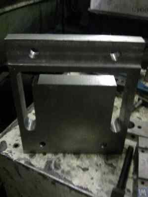
Sl. 3.12. Podupiranje sa tvrdim ležajevima za mašinu za balansiranje, proizvedeno od strane D. Krasilnikova
For machines with a balanced rotor mass not exceeding 300 – 500 kg, the thickness of the support can be increased to 30 – 40 mm, and for machines designed for balancing rotors with maximum masses ranging from 1000 to 3000 kg, the thickness of the support can reach 50 – 60 mm or more. As the analysis of the dynamic characteristics of the above-mentioned supports shows, their natural vibration frequencies, measured in the transverse plane (the plane of measurement of relative deformations of the “flexible” and “rigid” parts), usually exceed 100 Hz or more. The natural vibration frequencies of Hard Bearing support stands in the frontal plane, measured in the direction coinciding with the axis of rotation of the balanced rotor, are usually significantly lower. And it is these frequencies that should be primarily considered when determining the upper limit of the operating frequency range for rotating rotors balanced on the machine. As noted above, the determination of these frequencies can be performed by the impact excitation method described in section 3.1.
3.2. Potporni sklopovi mašina za balansiranje
3.2.1. Glavne vrste potpornih sklopova
U proizvodnji i mašina za balansiranje sa tvrdim ležajevima i sa mekim ležajevima, mogu se preporučiti sljedeće dobro poznate vrste nosnih sklopova, korištenih za instalaciju i rotaciju balansiranih rotora na podupiranjima, uključujući:
- Prizmatični nosivi sklopovi;
- Potporni sklopovi s rotirajućim valjcima;
- Nosivi sklopovi vretena.
3.2.1.1. Prizmatični potporni sklopovi
These assemblies, having various design options, are usually installed on supports of small and medium-sized machines, on which rotors with masses not exceeding 50 – 100 kg can be balanced. An example of the simplest version of a prismatic supporting assembly is presented in Figure 3.13. This supporting assembly is made of steel and is used on a turbine balancing machine. A number of manufacturers of small and medium-sized balancing machines, when manufacturing prismatic supporting assemblies, prefer to use non-metallic materials (dielectrics), such as textolite, fluoroplastic, caprolon, etc.
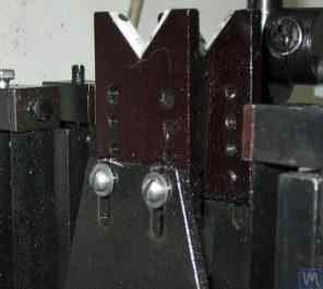
3.13. Varijanta izvođenja prizmatičnog nosnog sklopa, korištenog na mašini za balansiranje automobilskih turbina
Similar supporting assemblies (see Figure 3.8 above) are implemented, for example, by G. Glazov in his machine, also intended for balancing automobile turbines. The original technical solution of the prismatic supporting assembly, made of fluoroplastic (see Figure 3.14), is proposed by LLC “Technobalance”.
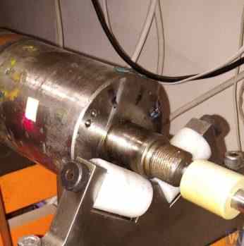
Sl. 3.14. Prizmatski sklop oslonca od LLC "Technobalance"
This particular supporting assembly is formed using two cylindrical sleeves 1 and 2, installed at an angle to each other and fixed on supporting axes. The balanced rotor contacts the surfaces of the sleeves along the generating lines of the cylinders, which minimizes the contact area between the rotor shaft and the support, consequently reducing the friction force in the support. If necessary, in case of wear or damage to the support surface in the area of its contact with the rotor shaft, the possibility of wear compensation is provided by rotating the sleeve around its axis by some angle. It should be noted that when using supporting assemblies made of non-metallic materials, it is necessary to provide for the structural possibility of grounding the balanced rotor to the machine body, which eliminates the risk of powerful static electricity charges occurring during operation. This, firstly, helps to reduce electrical interference and disturbances that may affect the performance of the machine’s measuring system, and secondly, eliminates the risk of personnel being affected by the action of static electricity.
3.2.1.2. Valjkasti potporni sklopovi
These assemblies are typically installed on supports of machines designed for balancing rotors with masses exceeding 50 kilograms and more. Their use significantly reduces friction forces in the supports compared to prismatic supports, facilitating the rotation of the balanced rotor. As an example, Figure 3.15 shows a design variant of a supporting assembly where rollers are used for the positioning of the product. In this design, standard rolling bearings are used as rollers 1 and 2, the outer rings of which rotate on stationary axes fixed in the body of the machine’s support 3. Figure 3.16 depicts a sketch of a more complex design of a roller supporting assembly implemented in their project by one of the self-made manufacturers of balancing machines. As seen from the drawing, in order to increase the load capacity of the roller (and consequently the supporting assembly as a whole), a pair of rolling bearings 1 and 2 is installed in the roller body 3. The practical implementation of this design, despite all its obvious advantages, appears to be a rather complex task, associated with the need for independent fabrication of the roller body 3, to which very high requirements for geometric accuracy and mechanical characteristics of the material are imposed.
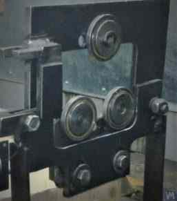
Sl. 3.15. Primjer dizajna nosnog sklopa sa valjcima
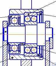
Sl. 3.16. Primjer dizajna nosnog sklopa sa valjcima sa dva kotrljajuća ležaja
Figure 3.17 presents a design variant of a self-aligning roller supporting assembly developed by the specialists of LLC “Technobalance”. In this design, the self-aligning capability of the rollers is achieved by providing them with two additional degrees of freedom, allowing the rollers to make small angular movements around the X and Y axes. Such supporting assemblies, ensuring high precision in the installation of balanced rotors, are usually recommended for use on supports of heavy balancing machines.
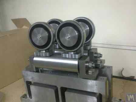
Sl. 3.17. Primjer dizajna samocentričnog nosnog sklopa sa valjcima
Kako je ranije spomenuto, nosni sklopovi sa valjcima obično imaju prilično visoke zahtjeve za preciznom izradom i krutošću. Posebno, tolerancije postavljene za radijalno bacanje valjaka ne smiju prelaziti 3-5 mikrona.
In practice, this is not always achieved even by well-known manufacturers. For example, during the author’s testing of the radial runout of a set of new roller support assemblies, purchased as spare parts for the balancing machine model H8V, brand “K. Shenk”, the radial runout of their rollers reached 10-11 microns.
3.2.1.3. Potporni sklopovi vretena
Pri balansiranju rotora sa montažom na flansu (na primjer, kardanskih vratila) na mašinama za balansiranje, vretena se koriste kao nosivi sklopovi za pozicioniranje, montažu i rotaciju balansiranih proizvoda.
Vretena su jedan od najkompleksnijih i najkritičnijih dijelova mašina za balansiranje, koji u velikoj mjeri odgovaraju za postizanje zahtijevanog kvaliteta balansiranja.
The theory and practice of designing and manufacturing spindles are quite well developed and are reflected in a wide range of publications, among which, the monograph “Details and Mechanisms of Metal-Cutting Machine Tools” [1], edited by Dr. Eng. D.N. Reshetov, stands out as the most useful and accessible for developers.
Među glavnim zahtjevima koje treba uzeti u obzir pri dizajniranju i proizvodnji vretena mašina za balansiranje, sljedeći bi trebali biti prioritet:
a) Osiguravanje visoke krutosti strukture sklopa vretena dovoljne da spriječi neprihvatljive deformacije koje se mogu javiti pod uticajem sila neuravnoteženosti balansiranog rotora;
b) Osiguravanje stabilnosti položaja ose rotacije vretena, karakterisane dopuštenim vrijednostima radijalnog, aksijalnog i aksijalnog bacanja vretena;
c) Osiguravanje odgovarajuće otpornosti na habanje rukavaca vretena, kao i njegovih sjedišta i nosnih površina korištenih za montažu balansiranih proizvoda.
Praktična implementacija ovih zahtjeva je detaljno opisana u sekciji VI "Vretena i njihovi oslonci" u radu [1].
Posebno, postoje metodologije za verifikaciju krutosti i rotacione preciznosti vretena, preporuke za odabir ležajeva, odabir materijala vretena i metode njegovog kaljenja, kao i mnogo druge korisne informacije na ovu temu.
Rad [1] napominje da se u dizajnu vretena za većinu vrsta mašina za obradu metala uglavnom koristi shema sa dva ležaja.
Primjer varijante dizajna takve sheme sa dva ležaja korištene u vretenu frezne mašine (detalji se mogu naći u radu [1]) prikazan je na Sl. 3.18.
Ova shema je prilično pogodna za proizvodnju vretena mašina za balansiranje, primjeri varijanti dizajna kojih su prikazani u nastavku na Slikama 3.19-3.22.
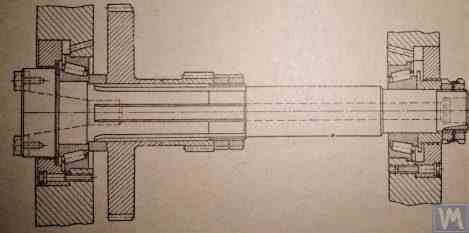
Sl. 3.18. Skica vretena frezne mašine sa dva ležaja
Slika 3.19 prikazuje jednu od varijanti dizajna vodećeg sklopa vretena mašine za balansiranje, koja se rotira na dva radijalno-aksijalna ležaja, od kojih svaki ima svoje nezavisno kućište 1 i 2. Na vratilo vretena 3 montirani su flans 4, namijenjen za montažu na flans kardanskog vratila, i kolut 5, korišten za prijenos rotacije na vreteno od električnog motora korištenjem klinastog kaiša.
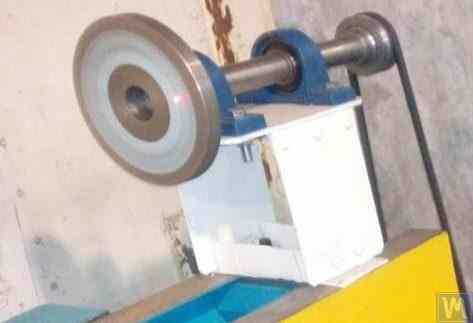
Slika 3.19. Primjer dizajna vretena na dva nezavisna ležajna podupiranja
Slike 3.20 i 3.21 prikazuju dva usko povezana dizajna vodećih sklopova vretena. U oba slučaja, ležajevi vretena su instalirani u zajedničkom kućištu 1, koje ima prolaznu aksijalnu rupu neophodnu za instalaciju vratila vretena. Na ulazu i izlazu ove rupe, kućište ima specijalne rupe (nisu prikazane na slikama), dizajnirane za smještaj radijalno-aksijalnih ležajeva (valjkastih ili kugličnih) i specijalne flans poklopce 5, korištene za fiksiranje vanjskih prstenova ležajeva.
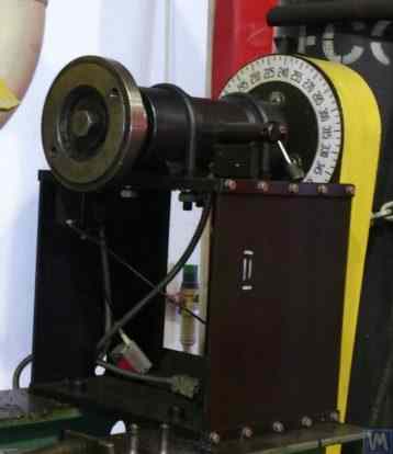
Slika 3.20. Primjer 1 dizajna vodećeg vretena na dva ležajna podupiranja instalirana u zajedničkom kućištu
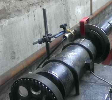
Slika 3.21. Primjer 2 dizajna vodećeg vratila na dva ležajna oslonca instalirana u zajedničkom kućištu
Kao i u prethodnoj verziji (vidi Sl. 3.19), na vratilu vretena postavljena je čeona ploča 2, namijenjena za flanšnu montažu pogonskog vratila, i kolut 3, koji služi za prijenos rotacije na vreteno od električnog motora putem kaišnog pogona. Na vratilu vretena je također fiksirana ugaona skala 4, koja se koristi za određivanje ugaonog položaja vretena pri postavljanju probnih i korekcijskih tegova na rotor tokom balansiranja.
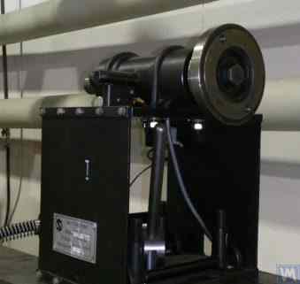
Slika 3.22. Primjer dizajna pogonskog (stražnjeg) vratila
Slika 3.22 prikazuje varijantu dizajna sklopa pogonjenog (stražnjeg) vretena mašine, koja se od vodećeg vretena razlikuje samo po odsustvu pogonskog koluta i kraka, jer oni nisu potrebni.
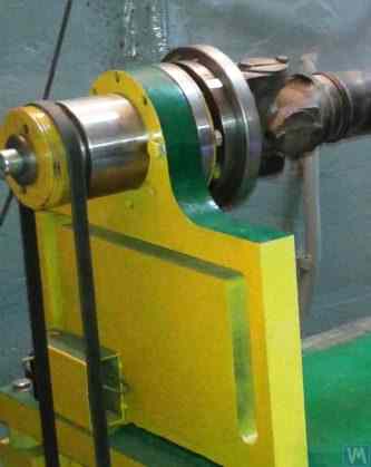
Slika 3.23. Primjer dizajna vretena na pogonu (stražnje)
Kao što se vidi na Slikama 3.20 – 3.22, gore navedeni sklopovi vratila pričvršćuju se na oslonce mekog ležaja balansnih mašina pomoću specijalnih steznih traka (remena) 6. Ukoliko je potrebno, mogu se koristiti i drugi načini pričvršćivanja, uz osiguranje odgovarajuće krutosti i preciznosti pozicioniranja sklopa vratila na osloncu.
Slika 3.23 ilustrira dizajn flansnog pričvršćivanja sličan onom za to vreteno, koji se može koristiti za njegovu instalaciju na oslonac tvrdog ležaja balansne mašine.
3.2.1.3.4. Izračunavanje krutosti vretena i radijalnog istrošenja
Za određivanje krutosti vretena i očekivanog radijalnog istrošenja, može se koristiti formula 3.4 (vidi shemu proračuna na slici 3.24):
gdje:
- Y - elastična deformacija vretena na kraju konzole vretena, cm;
- P - proračunska opterećenja koja djeluje na konzolu vretena, kg;
- A - stražnji oslonac sa kuglicama vretena;
- B - prednji oslonac sa kuglicama vretena;
- g - dužina konzole vretena, cm;
- c - rastojanje između oslonaca A i B vretena, cm;
- J1 – averaged moment of inertia of the spindle section between supports, cm⁴;
- J2 - prosječni moment inercije presjeka vretena konzole, cm⁴;
- jB i jA - krutost ležajeva za prednje i zadnje oslonce vretena, respektivno, kg/cm.
Transformacijom formule 3.4, željena proračunska vrijednost krutosti sklopa vratila jшп može se odrediti:
S obzirom na preporuke iz rada [1] za balansne mašine srednje veličine, ova vrijednost ne smije biti ispod 50 kg/µm.
Za proračun radijalnog radijusa okretanja koristi se formula 3.5:
gdje:
- ∆ je radijalno bacanje na kraju konzole vratila, µm;
- ∆B je radijalno bacanje prednjeg ležaja vratila, µm;
- ∆A je radijalno bacanje stražnjeg ležaja vratila, µm;
- g je dužina konzole vretena, cm;
- c je rastojanje između oslonaca A i B vratila, cm.
3.2.1.3.5. Osiguravanje zahtjeva za balansiranost vretena
Spindle assemblies of balancing machines must be well-balanced, as any actual imbalance will transfer to the rotor being balanced as additional error. When setting technological tolerances for the residual imbalance of the spindle, it is generally advised that the precision class of its balancing should be at least 1 – 2 classes higher than that of the product being balanced on the machine.
S obzirom na konstrukcijske karakteristike gore navedenih vratila, njihovo balansiranje treba izvesti u dvije ravnine.
3.2.1.3.6. Osiguravanje zahtjeva za nosivošću ležajeva i trajnošću ležajeva vratila
Prilikom projektovanja vretena i odabira veličina ležajeva preporučljivo je unaprijed procijeniti trajnost i nosivost ležajeva. Metodologija za izvođenje ovih proračuna može se detaljno naći u ISO 281 „Kotrljajući ležajevi – Dinamičke nosivosti i radni vijek” [3], kao i u brojnim (uključujući i digitalne) priručnicima za kotrljajuće ležajeve.
3.2.1.3.7. Osiguravanje zahtjeva za prihvatljivim zagrijavanjem ležajeva vratila
Prema preporukama iz rada [1], maksimalno dozvoljeno zagrijavanje vanjskih prstenova ležajeva vratila ne smije prelaziti 70°C. Međutim, kako bi se osiguralo visokokvalitetno balansiranje, preporučeno zagrijavanje vanjskih prstenova ne smije prelaziti 40 – 45°C.
3.2.1.3.8. Odabir tipa kaišnog pogona i dizajna pogonskog koluta za vratilo
Pri projektovanju pogonskog vretena mašine za balansiranje preporučuje se osigurati njegovu rotaciju pomoću pogona s ravnim kaišem. Primjer pravilne upotrebe takvog pogona za rad vretena predstavljen je na Slike 3.20 i 3.23. Upotreba klinastih ili zupčastih remenskih prenosa nije poželjna, jer mogu unijeti dodatna dinamička opterećenja na vreteno usljed geometrijskih netačnosti remena i remenica, što zauzvrat može dovesti do dodatnih grešaka mjerenja tokom balansiranja. Preporučeni zahtjevi za remenice za ravne pogonske remene navedeni su u nacionalnom standardu GOST 17383-73 „Remenice za ravne pogonske remene” [4].
Pogonski kolut treba pozicionirati na stražnji kraj vretena, što je bliže moguće sklopu ležaja (uz minimalno moguće izbočenje). Konstrukcijska odluka o izbočenom pozicioniranju koluta, donesena pri izradi vretena prikazanog na Slika 3.19, može se smatrati neuspješnom, jer značajno povećava moment dinamičkog opterećenja pogona koji djeluje na oslonce vratila.
Još jedan značajan nedostatak ovog dizajna je korištenje klinastog kaišnog pogona, čije netačnosti izrade i montaže također mogu biti izvor neželjenog dodatnog opterećenja na vreteno.
3.3. Postolje (okvir)
Postolje je glavna nosiva struktura balansne mašine, na kojoj se nalaze njeni glavni elementi, uključujući stubove nosača i pogonski motor. Pri odabiru ili izradi postolja balansne mašine, neophodno je osigurati da zadovoljava nekoliko zahtjeva, uključujući potrebnu krutost, geometrijsku preciznost, otpornost na vibracije i otpornost na habanje njegovih vodilja.
Praksa pokazuje da se pri izradi mašina za vlastite potrebe najčešće koriste sljedeće opcije postolja:
- livena postolja od rabljenih mašina za obradu metala (glodalice, strugovi, drvoobrade, itd.);
- montažna postolja od U-profila, sastavljena pomoću vijčanih spojeva;
- zavarena postolja na bazi U-profila;
- postolja od polimernog betona s premazima za apsorpciju vibracija.
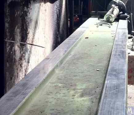
Slika 3.25. Primjer korištenja rabljenog postolja drvoobradne mašine za izradu mašine za balansiranje kardanskih vratila.
3.4. Pogoni za mašine za balansiranje
Kao što analiza konstrukcijskih rješenja koja naši klijenti koriste pri izradi balansnih mašina pokazuje, prilikom projektiranja pogona prvenstveno se oslanjaju na korištenje izmjeničnih motora opremljenih pretvaračima frekvencije. Ovaj pristup omogućuje širok raspon podesivih brzina rotacije za balansirane rotore uz minimalne troškove. Snaga glavnih pogonskih motora koji se koriste za rotaciju balansiranih rotora obično se odabire na temelju mase tih rotora i može približno iznositi:
- 0.25 - 0.72 kW za mašine predviđene za balansiranje rotora s masom ≤ 5 kg;
- 0.72 - 1.2 kW za mašine predviđene za balansiranje rotora s masom > 5 ≤ 50 kg;
- 1.2 - 1.5 kW za mašine predviđene za balansiranje rotora s masom > 50 ≤ 100 kg;
- 1.5 - 2.2 kW za mašine predviđene za balansiranje rotora s masom > 100 ≤ 500 kg;
- 2.2 - 5 kW za mašine predviđene za balansiranje rotora s masom > 500 ≤ 1000 kg;
- 5 - 7.5 kW za mašine predviđene za balansiranje rotora s masom > 1000 ≤ 3000 kg.
Ovi motori trebaju biti kruto montirani na postolje mašine ili njegov temelj. Prije ugradnje u mašinu (ili na mjestu ugradnje), glavni pogonski motor, zajedno s kolutom montiranim na njegovo izlazno vratilo, treba pažljivo balansirati. Kako bi se smanjile elektromagnetske smetnje uzrokovane pretvaračem frekvencije, preporučuje se ugradnja mrežnih filtera na njegovom ulazu i izlazu. To mogu biti standardni proizvodi dostupni u trgovini koje isporučuju proizvođači pretvarača ili samonapravljeni filteri izrađeni pomoću feritnih prstenova.
4. Mjerni sistemi balansirajućih mašina
Most amateur manufacturers of balancing machines, who contact LLC “Kinematics”, plan to use the “Balanset” series measurement systems manufactured by our company in their designs. However, there are also some customers who plan to manufacture such measuring systems independently. Therefore, it makes sense to discuss the construction of a measuring system for a balancing machine in more detail. The main requirement for these systems is the need to provide high-precision measurements of the amplitude and phase of the rotational component of the vibrational signal, which appears at the rotation frequency of the balanced rotor. This goal is usually achieved by using a combination of technical solutions, including:
- Korištenje senzora vibracija sa visokim koeficijentom pretvorbe signala;
- Upotreba modernih laserskih senzora faznog ugla;
- Izrada (ili korištenje) hardvera koji omogućava pojačavanje i digitalnu konverziju signala senzora (primarna obrada signala);
- Primjena softverske obrade vibracijskog signala, koja bi trebala omogućiti ekstrakciju visokog razlučivanja i stabilnu ekstrakciju rotacijske komponente vibracijskog signala, koja se manifestira na frekvenciji rotacije balansiranoga rotora (sekundarna obrada).
U nastavku razmatramo poznate varijante takvih tehnièkih rješenja, primijenjena u brojnim poznatim instrumentima za balansiranje.
4.1. Izbor senzora vibracija
U mjernim sistemima mašina za balansiranje mogu se koristiti razni tipovi senzora vibracija (pretvarača), uključujući:
- Senzori ubrzanja vibracija (akcelerometri);
- Senzori brzine vibracija;
- Senzori pomaka vibracija;
- Senzori sile.
4.1.1. Senzori ubrzanja vibracija
Among vibration acceleration sensors, piezo and capacitive (chip) accelerometers are the most widely used, which can be effectively used in Soft Bearing type balancing machines. In practice, it is generally permissible to use vibration acceleration sensors with conversion coefficients (Kpr) ranging from 10 to 30 mV/(m/s²). In balancing machines that require particularly high balancing accuracy, it is advisable to use accelerometers with Kpr reaching levels of 100 mV/(m/s²) and above. As an example of piezo accelerometers that can be used as vibration sensors for balancing machines, Figure 4.1 shows the DN3M1 and DN3M1V6 piezo accelerometers manufactured by LLC “Izmeritel”.
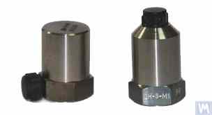
Slika 4.1. Piezo akcelerometri DN 3M1 i DN 3M1V6
Za povezivanje ovakvih senzora sa instrumentima i sistemima za mjerenje vibracija neophodno je koristiti vanjska ili ugrađena pojačala naboja.
Slika 4.2. Kapacitivni akcelometar AD1 proizvedenih od strane LLC "Kinematics" (Vibromera)
Treba napomenuti da ovi senzori, koji uključuju široko korištene tržišne ploče kapacitivnih akcelerometara ADXL 345 (vidi Sliku 4.3), imaju nekoliko značajnih prednosti u odnosu na piezo akcelerometre. Konkretno, oni su 4 do 8 puta jeftiniji uz slične tehničke karakteristike. Štaviše, ne zahtijevaju korištenje skupih i osjetljivih pojačala naboja potrebnih za piezo akcelerometre.
U slučajevima kada se oba tipa akcelerometara koriste u mjernim sistemima balansirnih mašina, obično se izvodi hardverska integracija (ili dvostruka integracija) signala senzora.
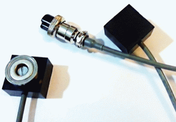
Slika 4.2. Kapacitivni akcelerometri AD 1, sastavljeni.
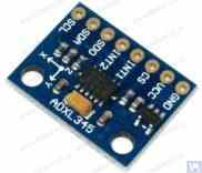
Slika 4.3. Ploča kapacitivnog akcelerometra ADXL 345.
U ovom slučaju, početni signal senzora, proporcionalan vibracijskom ubrzanju, se odgovarajuće transformiše u signal proporcionalan vibracijskoj brzini ili pomaku. Postupak dvostruke integracije vibracijskog signala je posebno relevantan pri korištenju akcelerometara kao dijela mjernih sistema za balansirne mašine niskih obrtaja, gdje donji opseg frekvencije rotacije rotora tokom balansiranja može doseći 120 obrtaja/min i niže. Pri korištenju kapacitivnih akcelerometara u mjernim sistemima balansirnih mašina, treba imati na umu da njihovi signali nakon integracije mogu sadržavati niskofrekventne smetnje, koje se manifestuju u frekvencijskom opsegu od 0,5 do 3 Hz. Ovo može ograničiti donji frekvencijski opseg balansiranja na mašinama namijenjenim za korištenje ovih senzora.
4.1.2. Senzori brzine vibracija
4.1.2.1. Induktivni senzori brzine vibracija.
Ovi senzori uključuju induktivnu zavojnicu i magnetsko jezgro. Kada se zavojnica vibrira u odnosu na fiksno jezgro (ili jezgro u odnosu na fiksnu zavojnicu), u zavojnici se indukuje EMF, čiji je napon direktno proporcionalan brzini vibracije pokretnog elementa senzora. Koeficijenti pretvorbe (Кпр) induktivnih senzora su obično prilično visoki, dostižući nekoliko desetina ili čak stotina mV/mm/sec. Posebno, koeficijent pretvorbe senzora Schenck modela T77 je 80 mV/mm/sec, a za senzor IRD Mechanalysis modela 544M iznosi 40 mV/mm/sec. U nekim slučajevima (na primjer, u Schenck balansirnim mašinama) koriste se specijalni visoko-osjetljivi induktivni senzori brzine vibracija sa mehaničkim pojačalom, gdje Кпр može premašiti 1000 mV/mm/sec. Ako se induktivni senzori brzine vibracija koriste u mjerne sisteme balansirnih mašina, može se izvršiti i hardverska integracija električnog signala proporcionalnog brzini vibracija, pretvarajući ga u signal proporcionalan pomaku vibracija.
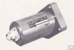
Slika 4.4. Senzor modela 544M kompanije IRD Mechanalysis.
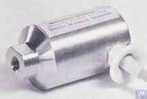
Slika 4.5. Senzor model T77 proizvođača Schenck
Treba napomenuti da su, zbog intenzivnosti rada u njihovoj proizvodnji, induktivni senzori brzine vibracija prilično rijetki i skupi artikli. Stoga, uprkos očiglednim prednostima ovih senzora, amaterski proizvođači balansirnih mašina ih vrlo rijetko koriste.
4.2. Senzori faznog ugla
For synchronizing the vibration measurement process with the rotation angle of the balanced rotor, phase angle sensors, such as laser (photoelectric) or inductive sensors, are used. These sensors are manufactured in various designs by both domestic and international producers. The price range for these sensors can vary significantly, from approximately 40 to 200 dollars. An example of such a device is the phase angle sensor manufactured by “Diamex,” shown in figure 4.11.
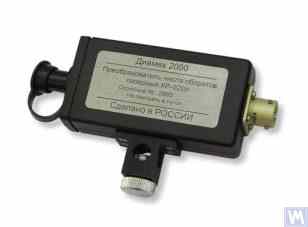
Slika 4.11: Senzor kuta faze tvrtke "Diamex"
Kao još jedan primjer, slika 4.12 pokazuje model primijenjen od strane LLC "Kinematics" (Vibromera), koji koristi laserske tahometre model DT 2234C proizvedene u Kini kao senzore kuta faze. Očigledne prednosti ovog senzora uključuju:
- Širok radni opseg, koji omogućava mjerenje frekvencije rotacije rotora od 2,5 do 99.999 obrtaja u minuti, sa rezolucijom od najmanje jednog obrtaja;
- Digitalni displej;
- Jednostavnost podešavanja tahometra za mjerenja;
- Pristupačnost i niska tržišna cijena;
- Relativna jednostavnost modifikacije za integraciju u mjerni sistem balansirne mašine.
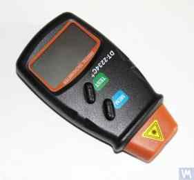
Slika 4.12: Laserski tahometar modela DT 2234C
U nekim slučajevima, kada je upotreba optičkih laserskih senzora iz bilo kojeg razloga nepoželjna, oni se mogu zamijeniti induktivnim beskontaktnim senzorima pomaka, kao što je prethodno spomenuti model ISAN E41A ili slični proizvodi drugih proizvođača.
4.3. Značajke obrade signala u senzorima vibracija
Za precizno mjerenje amplitude i faze rotacione komponente vibracionog signala u opremi za balansiranje obično se koristi kombinacija hardverskih i softverskih alata za obradu. Ovi alati omogućavaju:
- Širokopojasno filtriranje analognog signala senzora u hardveru;
- Pojačavanje analognog signala senzora;
- Integracija i/ili dvostruka integracija (ako je potrebno) analognog signala;
- Uskopojasno filtriranje analognog signala pomoću filtera za praćenje;
- Analogno-digitalna konverzija signala;
- Sinkrono filtriranje digitalnog signala;
- Harmonička analiza digitalnog signala.
4.3.1. Filtriranje širokopojasnog signala
Ova procedura je neophodna za čišćenje signala senzora vibracija od potencijalnih smetnji koje se mogu pojaviti i na donjoj i na gornjoj granici frekvencijskog opsega uređaja. Preporučljivo je da mjerni uređaj mašine za balansiranje postavi donju granicu propusnog filtera na 2-3 Hz, a gornju na 50 (100) Hz. „Niže“ filtriranje pomaže u suzbijanju niskofrekventnih šumova koji se mogu pojaviti na izlazu različitih tipova senzorskih mjernih pojačala. „Gornje“ filtriranje eliminiše mogućnost smetnji zbog kombinovanih frekvencija i potencijalnih rezonantnih vibracija pojedinih mehaničkih komponenti mašine.
4.3.2. Pojačanje analognog signala iz senzora
Ako postoji potreba za povećanjem osetljivosti mernog sistema balans mašine, signali sa senzora vibracija na ulaz merne jedinice mogu se pojačati. Mogu se koristiti i standardna pojačala sa konstantnim pojačanjem i višestepena pojačala čije pojačanje se može programski mijenjati u zavisnosti od stvarnog nivoa signala sa senzora. Primjer programabilnog višestepenog pojačala uključuje pojačala implementirana u pretvarače za mjerenje napona kao što su E154 ili E14-140 od strane LLC “L-Card”.
4.3.3. Integracija
Kao što je ranije navedeno, u mjernim sistemima mašina za balansiranje preporučuje se hardverska integracija i/ili dvostruka integracija signala senzora vibracija. Dakle, početni signal akcelerometra, proporcionalan vibro-ubrzanju, može se transformisati u signal proporcionalan vibro-brzini (integracija) ili vibro-pomaku (dvostruka integracija). Slično, signal senzora vibro brzine nakon integracije može se transformisati u signal proporcionalan vibro-pomaku.
4.3.4. Uskopojasno filtriranje analognog signala pomoću filtera za praćenje
Za smanjenje smetnji i poboljšanje kvaliteta obrade vibracijskog signala u mernim sistemima mašina za balansiranje mogu se koristiti uskopojasni filteri za praćenje. Centralna frekvencija ovih filtera se automatski podešava na frekvenciju rotacije balansiranog rotora koristeći signal senzora okretanja rotora. Za kreiranje ovakvih filtera mogu se koristiti moderna integrisana kola, kao što su MAX263, MAX264, MAX267, MAX268 kompanije MAXIM.
4.3.5. Analogno-digitalna konverzija signala
Analognodigualna konverzija je kritična procedura koja osigurava mogućnost poboljšanja kvalitete obrade vibracijskog signala tijekom mjerenja amplitude i faze. Ova procedura se primjenjuje u svim modernim mjernm sustavima mašina za balansiranje. Primjer učinkovite primjene takvih ADC-eva uključuje mjerače konverzije napona tipa E154 ili E14-140 tvrtke LLC "L-Card", koji se koriste u nekoliko mjernm sustava mašina za balansiranje proizvedenih od strane LLC "Kinematics" (Vibromera). Dodatno, LLC "Kinematics" (Vibromera) ima iskustva u upotrebi jeftinijih mikroprocesrorskih sustava temeljenih na kontrolerima "Arduino", mikrokontroleru PIC18F4620 tvrtke "Microchip", i sličnim uređajima.
4.1.2.2. Senzori brzine vibracije temeljeni na piezoelektričnim akcelerometrima
A sensor of this type differs from a standard piezoelectric accelerometer by having a built-in charge amplifier and integrator within its housing, which allows it to output a signal proportional to vibration velocity. For example, piezoelectric vibration velocity sensors manufactured by domestic producers (ZETLAB company and LLC “Vibropribor”) are shown in Figures 4.6 and 4.7.
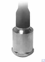
Slika 4.6. Senzor modela AV02 kompanije ZETLAB (Rusija)
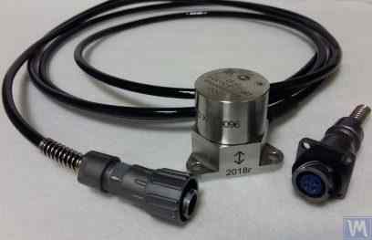
Slika 4.7. Senzor modela DVST 2 tvrtke LLC "Vibropribor"
Takve senzore proizvode različiti proizvođači (domaći i strani) i trenutno su široko korišteni, posebno u prijenosnoj vibracijskoj opremi. Trošak ovih senzora je prilično visok i može doseći 20.000 do 30.000 rubli po komadu, čak i od domaćih proizvođača.
4.1.3. Senzori pomaka
In the measurement systems of balancing machines, non-contact displacement sensors – capacitive or inductive – can also be used. These sensors can operate in static mode, allowing the registration of vibrational processes starting from 0 Hz. Their use can be particularly effective in the case of balancing low-speed rotors with rotation speeds of 120 rpm and below. The conversion coefficients of these sensors can reach 1000 mV/mm and higher, which provides high accuracy and resolution in measuring displacement, even without additional amplification. An obvious advantage of these sensors is their relatively low cost, which for some domestic manufacturers does not exceed 1000 rubles. When using these sensors in balancing machines, it is important to consider that the nominal working gap between the sensor’s sensitive element and the surface of the vibrating object is limited by the diameter of the sensor coil. For example, for the sensor shown in Figure 4.8, model ISAN E41A by “TEKO,” the specified working gap is typically 3.8 to 4 mm, which allows for the measurement of displacement of the vibrating object in the range of ±2.5 mm.
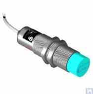
Slika 4.8. Induktivni senzor pomaka model ISAN E41A proizvođača TEKO (Rusija)
4.1.4. Senzori sile
Kako je ranije napomenuto, senzori sile koriste se u mjerne sisteme instalirane na balansirnim mašinama sa krutim ležajevima (Hard Bearing). Ovi senzori, posebno zbog jednostavnosti proizvodnje i relativno niskih troškova, su obično piezoelektrični senzori sile. Primjeri takvih senzora prikazani su na Slikama 4.9 i 4.10.
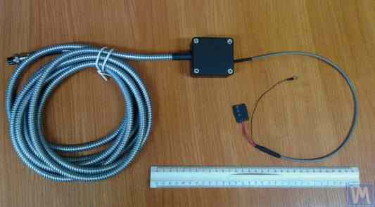
Slika 4.9. Senzor sile SD 1 kompanije Kinematika LLC
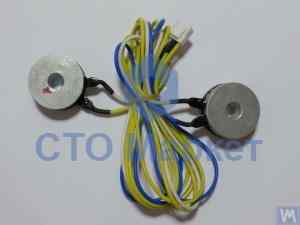
Slika 4.10: Senzor sile za automobilske mašine za balansiranje, prodaje "STO Market"
Senzori sile sa mjernim trakama (strain gauge), koje proizvodi širok spektar domaćih i stranih proizvođača, također se mogu koristiti za mjerenje relativnih deformacija u osloncima balansirnih mašina sa krutim ležajevima (Hard Bearing).
4.4. Funkcionalna šema sistema mjerenja mašine za balansiranje "Balanset 2"
Sistem za mjerenje "Balanset 2" predstavlja moderan pristup integraciji funkcija mjerenja i obrade podataka u mašinama za balansiranje. Ovaj sistem omogućava automatski izračun korektivnih masa koristeći metodu koeficijenta uticaja i može se prilagoditi raznim konfiguracijama mašina.
Funkcionalni šema obuhvata uslovno pojačavanje signala, analogno-digitalnu konverziju, obradu digitalnih signala i algoritme za automatski proračun. Sistem može rukovanje scenariji balansiranja s dva stanja korektivnih ravni i scenariji s više ravni sa visokom preciznošću.
4.5. Izračunavanje parametara korekcionih tegova korištenih pri balansiranju rotora
Proračun korektivnih masa temelji se na metodi koeficijenta uticaja, koja određuje kako se rotor odgovara na pokusne mase u različitim ravnima. Ova metoda je fundamentalna za sve moderne sisteme balansiranja i pruža tačne rezultate za krute i fleksibilne rotore.
4.5.1. Zadatak balansiranja rotora sa dva oslonca i metode njegovog rješavanja
Za rotore sa dva oslonca (najčešća konfiguracija), zadatak balansiranja uključuje određivanje dviju korektivnih masa - po jedna za svaku ravninu korekcije. Metoda koeficijenta uticaja koristi sljedeći pristup:
- Početno mjerenje (Pokus 0): Mjerenje vibracija bez pokusnih masa
- Prvi pokusni pokret (Pokus 1): Dodavanje poznatih pokusnih masa na ravninu 1, mjerenje odgovora
- Drugi pokusni pokret (Pokus 2): Prebacivanje pokusne mase na ravninu 2, mjerenje odgovora
- Proračun: Softver izračunava trajne korektivne mase na osnovu izmjerenih odgovora
Matematička osnova uključuje rješavanje sistema linearnih jednačina koje povezuju uticaje pokusnih masa sa potrebnim korekcijama u obe ravni istovremeno.
Slike 3.26 i 3.27 pokazuju primjere korištenja postolja strugova, na osnovu kojih su izrađene specijalizirana mašina s krutim ležajevima za balansiranje svrdla (pužnih vijaka) i univerzalna mašina s mekim ležajevima za balansiranje cilindričnih rotora. Za proizvođače koji rade sami (DIY), takva rješenja omogućuju stvaranje krutog nosivog sustava za balansnu mašinu uz minimalno vrijeme i troškove, na koji se mogu montirati nosivi stalci različitih tipova (i s krutim i s mekim ležajevima). Glavni zadatak proizvođača u ovom slučaju je osigurati (i po potrebi obnoviti) geometrijsku preciznost vodilica mašine na kojima će se osloniti nosivi stalci. U uvjetima samostalne proizvodnje, za obnovu potrebne geometrijske točnosti vodilica obično se koristi fino struganje (skrapiranje).
Slika 3.28 pokazuje verziju sklopnog postolja izrađenog od dva profila. Pri izradi ovog postolja koriste se odvojivi vijčani spojevi, što omogućuje minimiziranje ili potpuno eliminiranje deformacija postolja tijekom sastavljanja bez dodatnih tehnoloških operacija. Kako bi se osigurala odgovarajuća geometrijska točnost vodilica navedenog postolja, može biti potrebna mehanička obrada (brušenje, fino glodanje) gornjih krila korištenih profila.
Slike 3.29 i 3.30 predstavljaju varijante zavarenih postolja, također izrađenih od dva profila. Tehnologija izrade takvih postolja može zahtijevati niz dodatnih operacija, kao što je termička obrada za ublažavanje unutarnjih naprezanja koja nastaju tijekom zavarivanja. Kao i kod sklopnih postolja, kako bi se osigurala odgovarajuća geometrijska točnost vodilica zavarenih postolja, treba planirati mehaničku obradu (brušenje, fino glodanje) gornjih krila korištenih profila.
4.5.2. Metodologija dinamičkog balansiranja rotora sa više oslonaca
Rotori sa više oslonaca (tri ili četiri tačke oslanjanja) zahtijevaju složenije procedure balansiranja. Svaka tačka oslanjanja doprinosi ukupnom dinamičkom ponašanju, a korekcija mora uzeti u obzir interakcije između svih ravni.
Metodologija prosljeđuje pristup s dva stanja:
- Mjerenje vibracija na svim tačkama oslanjanja
- Korištenje više pozicija pokusnih masa
- Rješavanje većih sistema linearnih jednačina
- Optimiziranje distribucije korektivnih masa
Za kardanske vratile i slične dugačke rotore, ovaj pristup obično postiže nivoe rezidualnog neuravnoteženosti koja odgovara ISO klasama kvaliteta G6,3 ili boljim.
4.5.3. Kalkulatori za balansiranje rotora sa više oslonaca
Razvijeni su specijalizovani algoritmi izračunavanja za konfiguracije rotora sa tri oslonca i četiri oslonca. Ovi kalkulatori su implementirani u softveru Balanset-4 i mogu automatski da rukuju kompleksnim geometrijama rotora.
Kalkulatori uzimaju u obzir:
- Promenljivu krutost oslonaca
- Međuuticaj između ravni korekcije
- Optimizaciju postavljanja težina zbog pristupačnosti
- Verifikaciju izračunatih rezultata
5. Preporuke za provjeru rada i tačnosti balansirnih mašina
Tačnost i pouzdanost mašine za uravnotežavanje zavise od mnogih faktora, uključujući geometrijsku tačnost njenih mehaničkih komponenti, dinamičke karakteristike oslonaca i operativnu mogućnost sistema za merenje. Redovna verifikacija ovih parametara osigurava konzistentnu kvalitetu uravnotežavanja i pomaže da se identifikuju potencijalni problemi pre nego što utiču na proizvodnju.
5.1. Provjera geometrijske tačnosti mašine
Verifikacija geometrijske tačnosti uključuje proveru poravnanja oslonaca, paralelizma vodjica i koncentričnosti sklopova vratila. Ove provere bi trebalo da se obave tokom početne postavke i periodično tokom rada da bi se osigurala održana tačnost.
5.2. Provjera dinamičkih karakteristika mašine
Verifikacija dinamičkih karakteristika uključuje merenje prirodnih frekvencija oslonaca i komponenti ramy kako bi se osiguralo da su pravilno odvojena od operativnih frekvencija. Ovo sprečava probleme rezonancije koji mogu da ugroze tačnost uravnotežavanja.
5.3. Provjera operativne sposobnosti mjernog sistema
Verifikacija sistema za merenje uključuje kalibraciju senzora, verifikaciju faznog poravnanja i provere tačnosti obrade signala. Ovo osigurava pouzdano merenje amplitude i faze vibracija na svim operativnim brzinama.
5.4. Provjera karakteristika tačnosti prema ISO 21940-21 (ranije ISO 2953)
ISO 21940-21 (ranije ISO 2953) pruža standardizovane postupke za provjeru tačnosti mašina za balansiranje pomoću kalibrisanih probnih rotora. Ovi postupci pomažu u validaciji performansi mašine u odnosu na međunarodno priznate standarde.
Literatura
- Reshetov D.N. (urednik). "Detalji i mehanizmi metaloreznih mašina." Moskva: Mashinostroenie, 1972.
- Kellenberger W. "Spiralno brušenje cilindričnih površina." Machinery, 1963.
- ISO 281 „Kotrljajući ležajevi – Dinamičke nosivosti i radni vijek.”
- GOST 17383-73 (nacionalni standard) „Remenice za ravne pogonske remene.”
- ISO 21940-11 (ranije ISO 1940-1) „Mehaničke vibracije – Balansiranje rotora – Dio 11: Postupci i tolerancije za rotore s krutim ponašanjem.”
- ISO 21940-21 (ranije ISO 2953) „Mehaničke vibracije – Balansiranje rotora – Dio 21: Opis i ocjenjivanje mašina za balansiranje.”
Prilog 1: Algoritam za izračunavanje parametara balansiranja za tri oslonca vratila
Uravnotežavanje rotora sa tri oslonca zahteva rešavanje sistema od tri jednačine sa tri nepoznate. Ovaj prilog daje matematičku osnovu i korak-po-korak proceduru izračunavanja za određivanje korekcijskih težina u tri ravni korekcije.
A1.1. Matematička osnova
Za rotor sa tri oslonca, matrica koeficijenata uticaja povezuje efekte probne mase sa vibracijskih odgovora na svakoj lokaciji ležaja. Opšti oblik sistema jednačina je:
[V₂] = [A₂₁ A₂₂ A₂₃] [W₂]
[V₃] = [A₃₁ A₃₂ A₃₃] [W₃]
gdje:
- V₁, V₂, V₃ - vektori vibracija na osloncima 1, 2 i 3
- W₁, W₂, W₃ - korekcijske mase u ravnima 1, 2 i 3
- Aᵢⱼ - koeficijenti uticaja koji povezuju masu j sa vibracijom na osloncu i
A1.2. Procedura proračuna
- Inicijalna mjerenja: Zabilježite amplitudu i fazu vibracija na sva tri oslonca bez probnih masa
- Redoslijed primjene probne mase: Primjena poznate probne mase na svaku korekcijsku ravninu sekvencijalno, zapisivanje promjena vibracija
- Proračun koeficijenata uticaja: Odredite kako svaka probna masa utiče na vibraciju na svakom osloncu
- Rješenje matrice: Riješite sistem jednačina kako biste pronašli optimalne korekcijske mase
- Postavljanje mase: Instalirajte izračunate mase pod određenim uglovima
- Provjera: Potvrdite da rezidualna vibracija ispunjava specifikacije
A1.3. Posebna razmatranja za rotore sa tri oslonca
Konfiguracije sa tri oslonca se obično koriste za dugačke kardanske vratile gdje je srednji oslonac potreban kako bi se spriječilo preterano savijanje. Ključna razmatranja uključuju:
- Krutost srednjeg oslonca utiče na opštu dinamiku rotora
- Poravnanje oslonaca je kritično za točne rezultate
- Masa probne težine mora izazvati mjerljiv odgovor na svim osloncima
- Međusobna sprega između ravnina zahtijeva pažljivu analizu
Prilog 2: Algoritam za izračunavanje parametara balansiranja za četiri oslonca vratila
Balansiranje rotora na četiri oslonca predstavlja najsloženiju uobičajenu konfiguraciju, što zahtijeva rješavanje matričnog sistema 4x4. Ova konfiguracija je tipična za vrlo duge rotore kao što su valci papirne industrije, osovine tekstilne mehaničke opreme i teški industrijski rotori.
A2.1. Prošireni matematički model
Sistem sa četiri oslonca proširuje model sa tri oslonca sa dodatnim jednačinama koje računaju lokaciju četvrtog ležaja:
[V₂] = [A₂₁ A₂₂ A₂₃ A₂₄] [W₂]
[V₃] = [A₃₁ A₃₂ A₃₃ A₃₄] [W₃]
[V₄] = [A₄₁ A₄₂ A₄₃ A₄₄] [W₄]
A2.2. Postupak sekvencijalne probne težine
Postupak sa četiri oslonca zahtijeva pet mjernih pokretanja:
- Mjerenje 0: Inicijalno mjerenje na sva četiri oslonca
- Pokretanje 1: Probna težina u ravnini 1, mjerenje na svim osloncima
- Pokretanje 2: Probna težina u ravnini 2, mjerenje na svim osloncima
- Pokretanje 3: Probna težina u ravnini 3, mjerenje na svim osloncima
- Pokretanje 4: Probna težina u ravnini 4, mjerenje na svim osloncima
A2.3. Razmatranja optimizacije
Balansiranje sa četiri oslonca često omogućava multiple valjane rješenja. Proces optimizacije razmatra:
- Minimiziranje ukupne mase korekcijske težine
- Osiguranje pristupačnih lokacija za postavljanje težine
- Balansiranje proizvodnih tolerancija i troškova
- Ispunjavanje specificiranih granica rezidualne vibracije
Prilog 3: Vodič za korištenje kalkulatora balansera
Kalkulator balansirajućeg uređaja Balanset automatizira kompleksne matematičke postupke opisane u Appendixima 1 i 2. Ovaj vodiči pruža praktične upute za učinkovitim korištenjem kalkulatora sa DIY mašinama za balansiranje.
A3.1. Postavljanje i konfiguracija softvera
- Definicija mašine: Definirajte geometriju mašine, lokacije oslonaca i korekcijske površine
- Kalibracija senzora: Provjerite orijentaciju senzora i faktore kalibracije
- Priprema pokusne mase: Izračunajte odgovarajuću masu pokusne težine na osnovu karakteristika rotora
- Provjera sigurnosti: Potvrdi sigurne brzine rada i metode pričvršćivanja težine
A3.2. Slijed mjerenja
Kalkulator vodi korisnika kroz slijed mjerenja s povratnom informacijom u realnom vremenu o kvaliteti mjerenja i preporukama za poboljšanje omjera signal-buka.
A3.3. Interpretacija rezultata
Kalkulator pruža više oblika izlaza:
- Grafički prikazi vektora koji pokazuju zahtjeve za korekciju
- Specifikacije brojčane mase i kuta
- Metrijske kvalitete i indikatori pouzdanosti
- Preporuke za poboljšanje tačnosti mjerenja
A3.4. Rješavanje čestih problema
Česti problemi i rješenja pri korištenju kalkulatora s DIY mašinama:
- Nedovoljan odgovor pokusne težine: Povećajte masu pokusne težine ili provjerite montažu senzora
- Neusklađena mjerenja: Provjerite mehaničku integrnost, provjerite uvjete rezonancije
- Loši rezultati korekcije: Provjerite točnost mjerenja kuta, provjerite efekte unakrsnog spregnuća
- Greške softvera: Provjerite veze senzora, provjerite ulazne parametre, osigurajte stabilne okretaje

