A new industrial plant was getting ready to start production, and the rotor of its hammer crusher had to be balanced before the line went into continuous operation. We did the job in place, in the crusher's own bearings, with the Balanset-1A portable balancer and a laptop. This page shows the machine, each step we took with the instrument, and what the plant got out of it.
The machine and the task
The crusher is a hammer mill. Rows of swinging hammers hang on pins between steel discs, and the whole rotor is driven directly through a coupling by an AC-Motoren motor. The nameplate gives 55 kW and 2970 rpm at 50 Hz, so the rotor turns at almost 3000 rpm.
At that speed even a small mass error on the rotor becomes a large rotating force on the bearings, the frame and the foundation; the force grows with the square of the speed. The plant wanted a smooth start. An unbalanced rotor runs inefficiently, causes mechanical problems and can disrupt production soon after commissioning. That is why the rotor was balanced before the plant started, not after the first breakdown.


How we used Balanset-1A, step by step
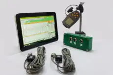
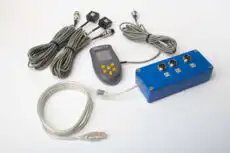
Balanset-1A measures the rotor in its own bearings at its working speed. The program leads you through the runs and calculates the correction itself; the person on site mounts the sensors and fixes the weights.
Sensors and tachometer
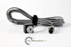
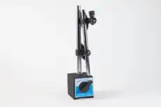
The vibration sensors go on the bearing housings, strictly radial, at right angles to the shaft, and on solid metal, not on guards or covers. A strip of reflective tape on the shaft is the phase reference: the laser tachometer reads it once per revolution. From now on neither the sensors nor the tape may move, because the program counts every angle from that mark.
Run 0: the initial vibration
The crusher is started with the hammers installed and brought up to working speed. One press of F7 records the amplitude, phase and speed of the vibration at the running frequency. This is the "before" picture of the unbalance.
Trial weight and Run 1
With the machine stopped and locked out, a trial weight of known mass is fixed to the rotor at a known radius, and its position is marked. The mass is chosen by force: at working speed its centrifugal force should be about 7 % of the rotor's weight (5–10 % is a sensible range).
The "First trial weight estimate" in the program, or our free trial weight calculator, gives the number for a given rotor mass, radius and speed.
Then the rotor runs again. If the trial weight changes the vibration too little, the program does not accept the run and asks for a heavier weight.
Calculation
From the difference between Run 0 and Run 1 the program calculates the influence coefficients and shows the correction: the mass in grams and the angle, counted from the trial weight position in the direction of rotation. The polar diagram shows where the weight goes.
Correction weight
The trial weight comes off, and the correction weight is fixed at the same radius and the indicated angle. The radius matters: the calculated mass is valid only at the radius where the trial weight sat.
Trim run
One more run at the same speed shows the residual vibration and the residual unbalance. With an ISO 21940-11 tolerance set, the program marks the result green or red. If a little more correction is needed, it calculates the addition straight away; no new trial run is required.

Crusher checks from the Balanset-1A manual
- Balance only with the hammers installed. Without them the unbalance comes back as soon as they are fitted.
- Swinging hammers can settle into a new position between runs. A stop/start test, two runs with nothing changed, shows whether the readings repeat.
- Many harmonics with a small component at the running frequency usually mean a drive problem, not unbalance. Check the drive chain, including the coupling, before adding weight.

Result
After the correction we ran the crusher again and checked it against the operating standards. The vibration was significantly lower, the rotor met the standards, and the crusher was cleared for continuous operation from the first day of production.
What the program records after the trim run
- Vibration before and after, and the reduction in percent.
- Initial and residual unbalance in g·mm, checked against the ISO 21940-11 tolerance: pass or fail.
- A ready HTML report and an archive record of the rotor, with the influence coefficients saved for the next balancing.
What it gave the plant
- The crusher went into production balanced, instead of being balanced after the first bearing failure.
- The work was done in place, in the machine's own bearings: the rotor was not removed or sent to a balancing shop.
- A record to come back to: the saved session is the starting point for future checks of the same rotor.
About the instrument
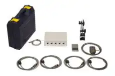
Balanset-1A is a two-channel portable balancer and vibration analyzer. It balances rotors in one or two planes in their own bearings, and the same kit works as a vibration meter and a spectrum analyzer. A crusher, a fan, a separator or a mulcher is balanced with the same procedure as on this page.



Nikolai Shelkovenko
Nikolai Shelkovenko is a vibration analysis engineer and the founder and CEO of Vibromera. For more than 15 years he has balanced rotating equipment in the field rather than on a test bench: mulchers, industrial fans, crushers, centrifuges, shafts and spindles. That work is what the Balanset instruments grew out of — they were designed as a tool a specialist can carry to the machine and use alone, on site, not as laboratory equipment. Vibromera was founded in 2017 and has been based in Porto, Portugal, since 2023. Development, assembly and support of the Balanset line all happen here. The flagship instrument is the Balanset-1A, a portable analyser for single- and two-plane balancing and for vibration diagnostics. Nikolai is personally involved in customer support, in working through difficult balancing cases and in the development of the software. He works with customers worldwide, in any language.