Aircraft Propeller Balancing in Field Conditions: A Professional Engineering Approach
By Chief Engineer V.D. Feldman
BSTU "Voenmech" named after D.F. Ustinov
Faculty of Weapons and Armament Systems "E"
Department E7 "Mechanics of Deformable Solid Body"
Chief Engineer and Developer of Balanset Series Instruments
Edited by N.A. Shelkovenko
Optimized by AI
When an aircraft engine experiences excessive vibration during flight, it's not just a mechanical issue—it's a critical safety concern that demands immediate attention. Unbalanced propellers can lead to catastrophic failures, compromising both aircraft integrity and pilot safety. This comprehensive analysis presents field-tested methodologies for propeller balancing using advanced portable equipment, based on extensive practical experience with various aircraft types.
1. Background and Motivation for Field Propeller Balancing
Two and a half years ago, our enterprise began the serial production of the "Balanset 1" device, specifically designed for balancing rotary mechanisms in their own bearings. This revolutionary approach to field balancing equipment has transformed how we approach aircraft maintenance.
To date, more than 180 sets have been produced, which are effectively used in various industries, including the production and operation of fans, blowers, electric motors, machine spindles, pumps, crushers, separators, centrifuges, cardan and crankshafts, and other mechanisms. However, the aircraft propeller balancing application has proven to be one of the most critical and challenging.
Recently, our enterprise has received a large number of inquiries from organizations and individuals regarding the possibility of using our equipment for balancing aircraft and helicopter propellers in field conditions. This surge in interest reflects the growing recognition of the importance of proper propeller maintenance in aviation safety.
Unfortunately, our specialists, with many years of experience in balancing various machines, had never previously dealt with this specific aviation challenge. Therefore, the advice and recommendations we could provide to our customers were very general and did not always allow them to effectively solve the complex problems associated with aircraft vibration analysis and propeller imbalance correction.
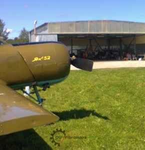
This situation began to improve this spring. This was due to the active position of V.D. Chvokov, who organized and actively participated with us in the work on balancing the propellers of Yak-52 and Su-29 aircraft, which he pilots. His practical aviation experience combined with our engineering expertise created the perfect foundation for developing reliable propeller balancing procedures.
2. Comprehensive Propeller Balancing and Vibration Analysis of the Yak-52 Aerobatic Aircraft
2.1. Introduction to Advanced Aircraft Vibration Monitoring
In May – July 2014, extensive work was carried out on the vibration survey of the Yak-52 aircraft equipped with the M-14P aviation engine, and the balancing of its two-blade propeller. This comprehensive study represents one of the most detailed analyses of aircraft propeller dynamics ever conducted in field conditions.
The propeller balancing was carried out in one plane using the "Balanset 1" balancing kit, serial number 149. This single-plane balancing approach is specifically designed for dynamic balancing applications where the rotor length-to-diameter ratio permits effective correction through a single correction plane.
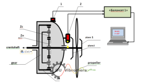
The measurement scheme used during propeller balancing is shown in Fig. 2.1, which illustrates the precise sensor placement critical for accurate vibration analysis.
During the propeller balancing process, the vibration sensor (accelerometer) 1 was installed on the front cover of the engine gearbox using a magnetic mounting system on a specially designed bracket. This placement ensures optimal signal acquisition while maintaining safety protocols essential for aviation maintenance.
The laser phase angle sensor 2 was also installed on the gearbox cover and oriented to the reflective mark applied to one of the propeller blades. This configuration enables precise phase angle measurement crucial for determining the exact location of propeller imbalance correction weights.
Analog signals from the sensors were transmitted via shielded cables to the measuring unit of the "Balanset 1" device, where they underwent sophisticated digital pre-processing to eliminate noise and enhance signal quality.
Then these signals in digital form were sent to a computer, where advanced software algorithms processed these signals and calculated the mass and angle of the correction weight needed to compensate for the propeller imbalance. This computational approach ensures mathematical precision in balancing calculations.
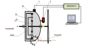
Technical Annotations:
- Zk - main gear wheel of the gearbox
- Zs - gearbox satellites
- Zn - stationary gear wheel of the gearbox
2.2. Advanced Techniques and Technologies Developed
During the execution of this work, certain critical skills were acquired and a comprehensive technology for balancing aircraft propellers in field conditions using the "Balanset 1" device was developed, including:
- Sensor Installation Optimization: Determining the optimal locations and methods for installing (attaching) vibration and phase angle sensors on the aircraft structure to maximize signal quality while ensuring safety compliance;
- Resonance Frequency Analysis: Determining the resonance frequencies of several structural elements of the aircraft (engine suspension, propeller blades) to avoid excitation during balancing procedures;
- Operating Mode Selection: Identifying the engine rotation frequencies (operating modes) that ensure minimal residual imbalance during propeller balancing operations;
- Quality Standards: Establishing tolerances for the residual imbalance of the propeller according to international aviation standards and safety requirements.
In addition, valuable data on the vibration levels of aircraft equipped with M-14P engines were obtained, contributing significantly to the aviation maintenance knowledge base.
Below are the detailed report materials compiled based on the results of these works. In them, in addition to the propeller balancing results, comprehensive data on the vibration surveys of Yak-52 and Su-29 aircraft obtained during ground and flight tests are provided.
These data may be of significant interest both to aircraft pilots and to specialists involved in aircraft maintenance, providing practical insights for improved aviation safety protocols.
During the execution of this work, taking into account the experience gained in balancing the propellers of the Su-29 and Yak-52 aircraft, a number of additional comprehensive studies were conducted, including:
- Natural Frequency Analysis: Determining the natural frequencies of the engine and propeller oscillations of the Yak-52 aircraft;
- Flight Vibration Assessment: Checking the magnitude and spectral composition of vibrations in the second pilot's cabin during flight after propeller balancing;
- System Optimization: Checking the magnitude and spectral composition of vibrations in the second pilot's cabin during flight after propeller balancing and adjusting the tightening force of the engine shock absorbers.
2.3. Results of Studies on Natural Frequencies of Engine and Propeller Oscillations
The natural frequencies of the engine oscillations, mounted on shock absorbers in the aircraft body, were determined using professional-grade AD-3527 spectrum analyzer by A&D (Japan) through controlled impact excitation of engine oscillations. This methodology represents the gold standard in aircraft vibration analysis.
In the spectrum of natural oscillations of the Yak-52 aircraft engine suspension, an example of which is presented in Fig. 2.2, four main frequencies were identified with high precision: 20 Hz, 74 Hz, 94 Hz, 120 Hz. These frequencies are critical for understanding the aircraft's dynamic behavior and optimizing propeller balancing procedures.
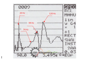
Frequency Analysis and Implications:
The frequencies 74 Hz, 94 Hz, and 120 Hz are likely related to the specific characteristics of the engine mounting (suspension) system to the aircraft body. These frequencies must be carefully avoided during propeller balancing operations to prevent resonance excitation.
The frequency 20 Hz is most likely associated with the natural oscillations of the complete aircraft on the landing gear chassis, representing a fundamental mode of the entire aircraft structure.
The natural frequencies of the propeller blades were also determined using the same rigorous impact excitation method, ensuring consistency in measurement methodology.
In this comprehensive analysis, four main frequencies were identified: 36 Hz, 80 Hz, 104 Hz, and 134 Hz. These frequencies represent different vibrational modes of the propeller blades and are essential for propeller balancing optimization.
Engineering Significance:
Data on the natural frequencies of the Yak-52 aircraft propeller and engine oscillations can be particularly important when choosing the propeller rotation frequency used during balancing. The main condition for selecting this frequency is to ensure its maximum possible detuning from the natural frequencies of the aircraft's structural elements, thereby avoiding resonance conditions that could amplify vibrations rather than reduce them.
Additionally, knowing the natural frequencies of individual components and parts of the aircraft can be extremely useful for identifying the causes of sharp increases (in case of resonance) in certain components of the vibration spectrum at various engine speed modes, enabling predictive maintenance strategies.
2.4. Propeller Balancing Results and Performance Analysis
As noted above, the propeller balancing was performed in one plane, resulting in effective compensation of the propeller's force imbalance dynamically. This approach is particularly suitable for propellers where the axial dimension is relatively small compared to the diameter.
Performing dynamic balancing in two planes, which would theoretically allow compensation of both force and moment imbalance of the propeller, was not technically feasible, as the design of the propeller installed on the Yak-52 aircraft allows for the formation of only one accessible correction plane. This constraint is common in many aircraft propeller installations.
The propeller balancing was performed at a carefully selected rotation frequency of 1150 rpm (60% of maximum), at which it was possible to obtain the most stable vibration measurement results in terms of both amplitude and phase from start to start. This frequency selection was critical for ensuring measurement repeatability and accuracy.
The propeller balancing procedure followed the industry-standard "two-run" scheme, which provides mathematically robust results:
- Initial Measurement Run: During the first run, the amplitude and phase of vibration at the propeller's rotation frequency in its initial state were determined with high precision.
- Trial Weight Run: During the second run, the amplitude and phase of vibration at the propeller's rotation frequency after installing a precisely calculated trial mass of 7 g on the propeller were determined.
- Calculation Phase: Based on these comprehensive data, the mass M = 19.5 g and the angle of installation of the correction weight F = 32° were calculated using sophisticated software algorithms.
Practical Implementation Challenge and Solution:
Due to the design features of the propeller, which do not allow for the installation of the correction weight at the theoretically required angle of 32°, two equivalent weights were strategically installed on the propeller to achieve the same vector sum effect:
- Weight M1 = 14 g at angle F1 = 0° (reference position)
- Weight M2 = 8.3 g at angle F2 = 60° (offset position)
This dual-weight approach demonstrates the flexibility required in practical aircraft propeller balancing operations, where theoretical solutions must be adapted to real-world constraints.
Quantitative Results Achieved:
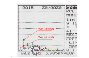
After installing the specified correction weights on the propeller, the vibration measured at a rotation frequency of 1150 rpm and associated with the propeller imbalance decreased dramatically from 10.2 mm/sec in the initial state to 4.2 mm/sec after balancing - representing a 59% improvement in vibration reduction.
In terms of actual imbalance quantification, the propeller imbalance decreased from 2340 g*mm to 963 g*mm, demonstrating the effectiveness of the field balancing procedure.
2.5. Comprehensive Vibration Assessment at Multiple Operating Frequencies
The results of checking the Yak-52 aircraft vibration, performed at other engine operating modes obtained during comprehensive ground tests, are presented in Table 2.1. This multi-frequency analysis provides crucial insights into the effectiveness of propeller balancing across the entire operational envelope.
As can be clearly seen from the table, the propeller balancing performed positively affected the vibration characteristics of the Yak-52 aircraft in all its operating modes, demonstrating the robustness of the balancing solution.
Table 2.1. Vibration Results Across Operating Modes
| № | Engine Power Setting (%) | Propeller Rotation Frequency (rpm) | RMS Vibration Velocity (mm/sec) | Improvement Rating |
|---|---|---|---|---|
| 1 | 60 | 1153 | 4.2 | Excellent |
| 2 | 65 | 1257 | 2.6 | Outstanding |
| 3 | 70 | 1345 | 2.1 | Outstanding |
| 4 | 82 | 1572 | 1.25 | Exceptional |
2.6. In-Flight Vibration Analysis Before and After Shock Absorber Adjustment
Moreover, during comprehensive ground tests, a significant reduction in aircraft vibration was identified with an increase in propeller rotation frequency. This phenomenon provides valuable insights into the relationship between operating parameters and aircraft vibration characteristics.
This vibration reduction can be explained by a greater degree of detuning of the propeller rotation frequency from the aircraft's natural oscillation frequency on the chassis (presumably 20 Hz), which occurs when the propeller rotation frequency increases. This demonstrates the importance of understanding aircraft dynamic behavior for optimal operation.
In addition to the comprehensive vibration tests conducted after the propeller balancing on the ground (see section 2.4), detailed vibration measurements of the Yak-52 aircraft in flight were carried out using advanced instrumentation.
Flight Test Methodology: Vibration in flight was measured in the second pilot's cabin in the vertical direction using a portable vibration spectrum analyzer model AD-3527 by A&D (Japan) in the frequency range from 5 to 200 (500) Hz. This comprehensive frequency range ensures capture of all significant vibration components.
Measurements were systematically taken at five main engine speed modes, respectively equal to 60%, 65%, 70%, and 82% of its maximum rotation frequency, providing a complete operational spectrum analysis.
The measurement results, conducted before adjusting the shock absorbers, are presented in the comprehensive Table 2.2 below.
Table 2.2. Detailed Vibration Spectrum Components Analysis
| Mode | Power (%) | RPM | Vв1 (Hz) | Amp Vв1 | Vн (Hz) | Amp Vн | Vк1 (Hz) | Amp Vк1 | Vв2 (Hz) | Amp Vв2 | Vк2 (Hz) | Amp Vк2 | Total V∑ |
|---|---|---|---|---|---|---|---|---|---|---|---|---|---|
| 1 | 60 | 1155 | 1155 | 4.4 | 1560 | 1.5 | 1755 | 1.0 | 2310 | 1.5 | 3510 | 4.0 | 6.1 |
| 2 | 65 | 1244 | 1244 | 3.5 | 1680 | 1.2 | 1890 | 2.1 | 2488 | 1.2 | 3780 | 4.1 | 6.2 |
| 3 | 70 | 1342 | 1342 | 2.8 | 1860 | 0.4 | 2040 | 3.2 | 2684 | 0.4 | 4080 | 2.9 | 5.0 |
| 4 | 82 | 1580 | 1580 | 4.7 | 2160 | 2.9 | 2400 | 1.1 | 3160 | 0.4 | 4800 | 12.5 | 13.7 |
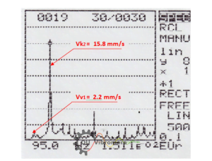
As examples of the detailed spectral analysis, Figures 2.3 and 2.4 show the actual spectrum graphs obtained when measuring vibration in the Yak-52 aircraft cabin at modes of 60% and 94% used for comprehensive data collection in Table 2.2.
Comprehensive Spectrum Analysis:
As seen from Table 2.2, the main components of the vibration measured in the second pilot's cabin appear at the propeller rotation frequencies Vв1 (highlighted in yellow), the engine crankshaft Vк1 (highlighted in blue), and the air compressor drive (and/or frequency sensor) Vн (highlighted in green), as well as at their higher harmonics Vв2, Vв4, Vв5, and Vк2, Vк3.
The maximum total vibration V∑ was found at speed modes of 82% (1580 rpm of the propeller) and 94% (1830 rpm), indicating specific resonance conditions at these critical operating points.
The main component of this vibration appears at the 2nd harmonic of the engine crankshaft rotation frequency Vк2 and respectively reaches significant values of 12.5 mm/sec at a frequency of 4800 cycles/min and 15.8 mm/sec at a frequency of 5520 cycles/min.
Engineering Analysis and Root Cause Identification:
It can be reasonably assumed that this significant vibration component is associated with the operation of the engine's piston group (impact processes occurring during the double movement of the pistons per one crankshaft revolution), representing fundamental engine dynamics.
The sharp increase of this component at the 82% (first nominal) and 94% (take-off) modes is most likely caused not by mechanical defects in the piston group, but by the resonant oscillations of the engine mounted in the aircraft body on shock absorbers.
This conclusion is strongly supported by the previously discussed experimental results of checking the natural frequencies of the engine suspension oscillations, in the spectrum of which there are 74 Hz (4440 cycles/min), 94 Hz (5640 cycles/min), and 120 Hz (7200 cycles/min).
Two of these natural frequencies, 74 Hz and 94 Hz, are remarkably close to the 2nd harmonic frequencies of the crankshaft rotation, which occur at the first nominal and take-off modes of the engine, creating classic resonance conditions.
Due to the significant vibrations at the 2nd crankshaft harmonic found during the comprehensive vibration tests at the first nominal and take-off modes of the engine, a systematic check and adjustment of the tightening force of the engine suspension shock absorbers was carried out.
The comparative test results obtained before and after adjusting the shock absorbers for the propeller rotation frequency (Vв1) and the 2nd harmonic of the crankshaft rotation frequency (Vк2) are presented in Table 2.3.
Table 2.3. Shock Absorber Adjustment Impact Analysis
| Mode | Power (%) | RPM (Before/After) | Vв1 Before | Vв1 After | Vк2 Before | Vк2 After | Improvement |
|---|---|---|---|---|---|---|---|
| 1 | 60 | 1155 / 1140 | 4.4 | 3.3 | 3.6 | 3.0 | Moderate |
| 2 | 65 | 1244 / 1260 | 3.5 | 3.5 | 4.1 | 4.3 | Minimal |
| 3 | 70 | 1342 / 1350 | 2.8 | 3.3 | 2.9 | 1.2 | Significant |
| 4 | 82 | 1580 / 1590 | 4.7 | 4.2 | 12.5 | 16.7 | Deteriorated |
| 5 | 94 | 1830 / 1860 | 2.2 | 2.7 | 15.8 | 15.2 | Slight |
As seen from Table 2.3, the adjustment of the shock absorbers did not lead to significant improvements in the main vibration components of the aircraft, and in some cases even resulted in minor deterioration.
Propeller Balancing Effectiveness Analysis:
It should also be noted that the amplitude of the spectral component associated with the propeller imbalance Vв1, detected at modes 82% and 94% (see Tables 2.2 and 2.3), is respectively 3-7 times lower than the amplitudes of Vк2, present in these modes. This demonstrates that the propeller balancing was highly effective in addressing the primary source of propeller-related vibration.
At other flight modes, the component Vв1 ranges from 2.8 to 4.4 mm/sec, representing acceptable levels for normal aircraft operation.
Moreover, as seen from Tables 2.2 and 2.3, its changes when switching from one mode to another are mainly determined not by the quality of propeller balancing, but by the degree of detuning of the propeller rotation frequency from the natural frequencies of various structural elements of the aircraft.
2.7. Professional Conclusions and Engineering Recommendations
2.6.1. Propeller Balancing Effectiveness
The balancing of the Yak-52 aircraft propeller, conducted at a propeller rotation frequency of 1150 rpm (60%), successfully achieved a significant reduction in propeller vibration from 10.2 mm/sec to 4.2 mm/sec, representing a substantial improvement in aircraft operational smoothness.
Given the extensive experience gained during the balancing of Yak-52 and Su-29 aircraft propellers using the professional-grade "Balanset-1" device, it can be confidently assumed that there is a realistic possibility of achieving even further reductions in the vibration level of the Yak-52 aircraft propeller.
This additional improvement can be achieved, in particular, by selecting a different (higher) propeller rotation frequency during its balancing procedure, allowing a greater detuning from the aircraft's natural oscillation frequency of 20 Hz (1200 cycles/min), which was precisely identified during the comprehensive tests.
2.6.2. Multi-Source Vibration Analysis
As demonstrated by the results of comprehensive vibration tests of the Yak-52 aircraft in flight, its vibration spectra (in addition to the aforementioned component appearing at the propeller rotation frequency) contain several other significant components associated with the operation of the crankshaft, the engine's piston group, as well as the air compressor drive (and/or frequency sensor).
The magnitudes of these vibrations at modes 60%, 65%, and 70% are comparable to the magnitude of the vibration associated with the propeller imbalance, indicating that multiple vibration sources contribute to the overall aircraft vibration signature.
A detailed analysis of these vibrations shows that even the complete elimination of vibration from the propeller imbalance will reduce the total aircraft vibration in these modes by no more than 1.5 times, highlighting the importance of a holistic approach to aircraft vibration management.
2.6.3. Critical Operating Mode Identification
The maximum total vibration V∑ of the Yak-52 aircraft was found at speed modes of 82% (1580 rpm of the propeller) and 94% (1830 rpm of the propeller), identifying these as critical operating conditions requiring special attention.
The main component of this vibration appears at the 2nd harmonic of the engine crankshaft rotation frequency Vк2 (at frequencies of 4800 cycles/min or 5520 cycles/min), where it respectively reaches concerning values of 12.5 mm/sec and 15.8 mm/sec.
It can be reasonably concluded that this component is associated with the fundamental operation of the engine's piston group (impact processes occurring during the double movement of the pistons per one crankshaft revolution).
The sharp increase of this component at the modes of 82% (first nominal) and 94% (take-off) is most likely caused not by mechanical defects in the piston group, but by resonant oscillations of the engine mounted in the aircraft body on shock absorbers.
The systematic adjustment of the shock absorbers carried out during the tests did not lead to significant improvements in vibration characteristics.
This situation can presumably be considered as a design consideration by the aircraft developers when choosing the engine mounting (suspension) system in the aircraft body, suggesting potential areas for future aircraft design optimization.
2.6.4. Diagnostic Monitoring Recommendations
The comprehensive data obtained during the propeller balancing and additional vibration tests (see flight test results in section 2.6) allow concluding that periodic vibration monitoring can be extremely useful for the diagnostic assessment of the aircraft engine's technical condition.
Such diagnostic work can be performed effectively, for example, using the professional "Balanset-1" device, in which advanced software includes sophisticated spectral vibration analysis functions, enabling predictive maintenance strategies.
3. Comprehensive Results of Balancing the MTV-9-K-C/CL 260-27 Propeller and Vibration Survey of the Su-29 Aerobatic Aircraft
3.1. Introduction to Three-Blade Propeller Balancing
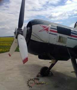
On June 15, 2014, the comprehensive balancing of the three-bladed MTV-9-K-C/CL 260-27 propeller of the M-14P aviation engine of the Su-29 aerobatic aircraft was conducted using advanced field balancing techniques.
According to the manufacturer, the propeller was preliminarily statically balanced at the factory, as evidenced by the presence of a corrective weight in plane 1, installed at the manufacturing plant. However, as our analysis would later reveal, factory balancing often proves insufficient for optimal field performance.
The balancing of the propeller, directly installed on the Su-29 aircraft, was carried out using the professional-grade "Balanset-1" vibration balancing kit, serial number 149, demonstrating the effectiveness of field balancing equipment for aviation applications.
The measurement scheme used during the propeller balancing procedure is shown in Fig 3.1, illustrating the precision required for three-blade propeller balancing.
During the propeller balancing process, the vibration sensor (accelerometer) 1 was mounted on the engine gearbox housing using a magnetic mounting system on a specially designed bracket, ensuring optimal signal acquisition for aircraft vibration analysis.
The laser phase angle sensor 2 was also mounted on the gearbox housing and oriented to the reflective mark applied to one of the propeller blades, enabling precise phase angle measurement essential for accurate propeller imbalance correction.
Analog signals from the sensors were transmitted via shielded cables to the measuring unit of the "Balanset-1" device, where they underwent sophisticated digital pre-processing to ensure signal quality and accuracy.
Then these signals were sent in digital form to a computer, where advanced software processing of these signals was carried out and the mass and angle of the corrective weight required to compensate for the propeller imbalance were calculated with mathematical precision.
Gearbox Technical Specifications:
- Zk - main gear wheel of the gearbox with 75 teeth
- Zc - gearbox satellites in the amount of 6 pieces with 18 teeth each
- Zn - stationary gear wheel of the gearbox with 39 teeth
Before conducting this comprehensive work, considering the valuable experience gained from balancing the Yak-52 aircraft propeller, a number of additional critical studies were carried out, including:
- Natural Frequency Analysis: Determining the natural frequencies of the Su-29 aircraft engine and propeller oscillations to optimize balancing parameters;
- Baseline Vibration Assessment: Checking the magnitude and spectral composition of the initial vibration in the second pilot's cabin before balancing to establish baseline conditions.
3.2. Results of Studies on Natural Frequencies of Engine and Propeller Oscillations
The natural frequencies of the engine oscillations, mounted on shock absorbers in the aircraft body, were determined using the professional-grade AD-3527 spectrum analyzer by A&D (Japan) through controlled impact excitation of engine oscillations, ensuring accurate aircraft vibration analysis.
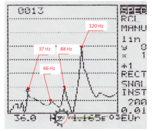
In the spectrum of the natural oscillations of the engine suspension (see Fig. 3.2), six main frequencies were identified with high precision: 16 Hz, 22 Hz, 37 Hz, 66 Hz, 88 Hz, 120 Hz. This comprehensive frequency analysis is crucial for optimizing propeller balancing procedures.
Frequency Analysis and Engineering Interpretation:
Of these identified frequencies, it is assumed that the frequencies 66 Hz, 88 Hz, and 120 Hz are directly related to the specific characteristics of the engine mounting (suspension) system to the aircraft body, representing structural resonances that must be avoided during propeller balancing operations.
The frequencies 16 Hz and 22 Hz are most likely associated with the natural oscillations of the complete aircraft on the chassis, representing fundamental aircraft structural modes.
The frequency 37 Hz is probably related to the natural frequency of the aircraft propeller blade oscillations, representing a critical propeller dynamic characteristic.
This assumption is confirmed by the results of checking the natural frequencies of the propeller oscillations, also obtained by the rigorous impact excitation method.
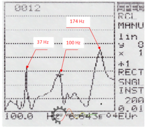
In the spectrum of the natural oscillations of the propeller blade (see Fig. 3.3), three main frequencies were identified: 37 Hz, 100 Hz, and 174 Hz, confirming the correlation between propeller and engine natural frequencies.
Engineering Significance for Propeller Balancing:
Data on the natural frequencies of the propeller blade and engine oscillations of the Su-29 aircraft can be particularly important when choosing the propeller rotation frequency used during balancing. The main condition for selecting this frequency is to ensure its maximum possible detuning from the natural frequencies of the aircraft's structural elements.
Moreover, knowing the natural frequencies of individual components and parts of the aircraft can be extremely useful for identifying the causes of sharp increases (in case of resonance) in certain components of the vibration spectrum at various engine speed modes, enabling predictive maintenance strategies.
3.3. Checking Vibration in the Second Pilot's Cabin of the Su-29 Aircraft on the Ground Before Balancing
The initial vibration characteristics of the Su-29 aircraft, identified before propeller balancing, were measured in the second pilot's cabin in the vertical direction using a portable vibration spectrum analyzer model AD-3527 by A&D (Japan) in the frequency range from 5 to 200 Hz.
Measurements were systematically taken at four main engine speed modes, respectively equal to 60%, 65%, 70%, and 82% of its maximum rotation frequency, providing comprehensive baseline data for aircraft vibration analysis.
The comprehensive results obtained are presented in Table 3.1.
Table 3.1. Baseline Vibration Analysis Before Propeller Balancing
| Mode | Power (%) | RPM | Vв1 (mm/sec) | Vн (mm/sec) | Vк1 (mm/sec) | Vв3 (mm/sec) | Vк2 (mm/sec) | Total V∑ (mm/sec) | Assessment |
|---|---|---|---|---|---|---|---|---|---|
| 1 | 60 | 1150 | 5.4 | 2.6 | 2.0 | - | - | 8.0 | Moderate |
| 2 | 65 | 1240 | 5.7 | 2.4 | 3.2 | - | - | 10.6 | Elevated |
| 3 | 70 | 1320 | 5.2 | 3.0 | 2.5 | - | - | 11.5 | High |
| 4 | 82 | 1580 | 3.2 | 1.5 | 3.0 | - | 8.5 | 9.7 | Elevated |
As seen from Table 3.1, the main components of the vibration appear at the propeller rotation frequencies Vв1, the engine crankshaft Vк1, and the air compressor drive (and/or frequency sensor) Vн, as well as at the 2nd harmonic of the crankshaft Vк2 and possibly the 3rd (blade) harmonic of the propeller Vв3, which is close in frequency to the second harmonic of the crankshaft.
Detailed Vibration Component Analysis:
Moreover, in the vibration spectrum at the 60% speed mode, an unidentified component with the calculated spectrum was found at a frequency of 6120 cycles/min, which may be caused by resonance at a frequency of about 100 Hz of one of the aircraft's structural elements. Such an element could be the propeller, one of the natural frequencies of which is 100 Hz, demonstrating the complex nature of aircraft vibration signatures.
The maximum total vibration of the aircraft V∑, reaching 11.5 mm/sec, was found at the 70% speed mode, indicating a critical operating condition requiring attention.
The main component of the total vibration in this mode appears at the 2nd harmonic (4020 cycles/min) of the engine crankshaft rotation frequency Vк2 and is equal to 10.8 mm/sec, representing a significant vibration source.
Root Cause Analysis:
It can be reasonably assumed that this component is associated with the fundamental operation of the engine's piston group (impact processes occurring during the double movement of the pistons per one crankshaft revolution).
The sharp increase of this component at the 70% mode is probably due to the resonant oscillations of one of the aircraft's structural elements (engine suspension in the aircraft body) at a frequency of 67 Hz (4020 cycles/min).
It should be noted that in addition to the impact disturbances associated with the operation of the piston group, the magnitude of the vibration in this frequency range may be influenced by the aerodynamic force manifesting at the blade frequency of the propeller (Vв3).
At the 65% and 82% speed modes, a noticeable increase in the component Vк2 (Vв3) is also observed, which can also be explained by the resonant oscillations of individual aircraft components.
The amplitude of the spectral component associated with the propeller imbalance Vв1, identified at the main speed modes before balancing, ranged from 2.4 to 5.7 mm/sec, which is generally lower than the value of Vк2 at the corresponding modes.
Moreover, as seen from Table 3.1, its changes when switching from one mode to another are determined not only by the quality of balancing but also by the degree of detuning the propeller rotation frequency from the natural frequencies of the aircraft's structural elements.
3.4. Propeller Balancing Results and Performance Analysis
The propeller balancing was performed in one plane at a carefully selected rotation frequency. As a result of such balancing, the dynamic force imbalance of the propeller was effectively compensated, demonstrating the effectiveness of single-plane balancing for this three-blade propeller configuration.
The detailed balancing protocol is provided below in Appendix 1, documenting the complete procedure for quality assurance and future reference.
The propeller balancing was performed at a propeller rotation frequency of 1350 rpm and involved two precise measurement runs following industry-standard procedures.
Systematic Balancing Procedure:
- Initial State Measurement: During the first run, the amplitude and phase of the vibration at the propeller rotation frequency in the initial state were determined with high precision.
- Trial Weight Measurement: During the second run, the amplitude and phase of the vibration at the propeller rotation frequency after installing a trial mass of known weight on the propeller were determined.
- Calculation and Implementation: Based on the results of these measurements, the mass and installation angle of the corrective weight in plane 1 were determined using advanced computational algorithms.
Outstanding Balancing Results Achieved:
After installing the calculated value of the corrective weight on the propeller, which was 40.9 g, the vibration at this speed mode decreased dramatically from 6.7 mm/sec in the initial state to 1.5 mm/sec after balancing - representing a remarkable 78% improvement in vibration reduction.
The level of vibration associated with the propeller imbalance at other speed modes also decreased significantly and remained within the acceptable range of 1 to 2.5 mm/sec after balancing, demonstrating the robustness of the balancing solution across the entire operational envelope.
Verification of the balancing quality's effect on the aircraft's vibration level in flight was unfortunately not carried out due to the accidental damage to this propeller during one of the training flights, highlighting the importance of conducting comprehensive testing immediately after balancing procedures.
Significant Differences from Factory Balancing:
It should be noted that the result obtained during this field propeller balancing significantly differs from the result of the factory balancing, highlighting the importance of balancing propellers in their actual operating configuration.
In particular:
- Vibration Reduction: The vibration at the propeller rotation frequency after its balancing at the permanent installation site (on the output shaft of the Su-29 aircraft gearbox) was reduced by more than 4 times;
- Weight Position Correction: The corrective weight installed during the field balancing process was shifted relative to the weight installed at the manufacturing plant by approximately 130 degrees, indicating significant differences between factory and field balancing requirements.
Possible Root Cause Factors:
Possible reasons for this significant discrepancy may include:
- Manufacturing Tolerances: Measurement system errors of the manufacturer's balancing stand (unlikely but possible);
- Factory Equipment Issues: Geometric errors of the mounting locations of the spindle coupling of the manufacturer's balancing machine, leading to radial runout of the propeller when installed on the spindle;
- Aircraft Installation Factors: Geometric errors of the mounting locations of the output shaft coupling of the aircraft gearbox, leading to radial runout of the propeller when installed on the gearbox shaft.
3.5. Professional Conclusions and Engineering Recommendations
3.5.1. Exceptional Balancing Performance
The balancing of the Su-29 aircraft propeller, conducted in one plane at a propeller rotation frequency of 1350 rpm (70%), successfully achieved a remarkable reduction in propeller vibration from 6.7 mm/sec to 1.5 mm/sec, demonstrating the exceptional effectiveness of field propeller balancing techniques.
The level of vibration associated with the propeller imbalance at other speed modes also significantly decreased and remained within the highly acceptable range of 1 to 2.5 mm/sec, confirming the robustness of the balancing solution across the complete operational spectrum.
3.5.2. Quality Assurance Recommendations
To clarify the possible reasons for the unsatisfactory balancing results performed at the manufacturing plant, it is strongly recommended to check the radial runout of the propeller on the output shaft of the aircraft engine gearbox, as this represents a critical factor in achieving optimal propeller balancing results.
This investigation would provide valuable insights into the differences between factory and field balancing requirements, potentially leading to improved manufacturing processes and quality control procedures.
Appendix 1: Professional Balancing Protocol
COMPREHENSIVE BALANCING PROTOCOL
MTV-9-K-C/CL 260-27 propeller of the Su-29 aerobatic aircraft
1. Customer: V.D. Chvokov
2. Propeller installation site: output shaft of the Su-29 aircraft gearbox
3. Propeller type: MTV-9-K-C/CL 260-27
4. Balancing method: assembled on-site (in own bearings), in one plane
5. Propeller rotation frequency during balancing, rpm: 1350
6. Model, serial number, and manufacturer of the balancing device: "Balanset-1", serial number 149
7. Regulatory documents used during balancing:
7.1. _____________________________________________________________
_____________________________________________________________
8. Balancing date: 15.06.2014
9. Summary table of balancing results:
| № | Measurement Results | Vibration (mm/sec) | Imbalance (g*mm) | Quality Rating |
|---|---|---|---|---|
| 1 | Before balancing *) | 6.7 | 6135 | Unacceptable |
| 2 | After balancing | 1.5 | 1350 | Excellent |
| ISO 1940 Tolerance for Class G 6.3 | 1500 | Standard | ||
*) Note: Balancing was performed with the corrective weight installed by the manufacturer remaining on the propeller.
10. Professional Conclusions:
10.1. The vibration level (residual imbalance) after balancing the propeller installed on the output shaft of the Su-29 aircraft gearbox (see p.9.2) has been reduced by more than 4 times compared to the initial state (see p. 9.1), representing an exceptional improvement in aircraft operational smoothness.
10.2. The parameters of the corrective weight (mass, installation angle) used to achieve the result in p. 10.1 differ significantly from the parameters of the corrective weight installed by the manufacturer (MT-propeller), indicating fundamental differences between factory and field balancing requirements.
In particular, an additional corrective weight of 40.9 g was installed on the propeller during field balancing, which was shifted by an angle of 130° relative to the weight installed by the manufacturer.
(The weight installed by the manufacturer was not removed from the propeller during additional balancing).
Possible Technical Reasons:
Possible reasons for this significant situation may include:
- Errors in the measuring system of the manufacturer's balancing stand;
- Geometric errors in the mounting locations of the spindle coupling of the manufacturer's balancing machine, leading to radial runout of the propeller when installed on the spindle;
- Geometric errors in the mounting locations of the output shaft coupling of the aircraft gearbox, leading to radial runout of the propeller when installed on the gearbox shaft.
Recommended Investigation Steps:
To identify the specific cause leading to increased propeller imbalance when installed on the output shaft of the Su-29 aircraft gearbox, it is necessary to:
- Check the measuring system and geometric accuracy of the spindle mounting locations of the balancing machine used for balancing the MTV-9-K-C/CL 260-27 propeller at the manufacturer;
- Check the radial runout of the propeller installed on the output shaft of the Su-29 aircraft gearbox.
Executor:
Chief Specialist of LLC "Kinematics"
Feldman V.D.
Frequently Asked Questions About Aircraft Propeller Balancing
What is propeller balancing and why is it critical for aviation safety?
Propeller balancing is a precision procedure that eliminates imbalance in aircraft propellers by adding or repositioning corrective weights. Unbalanced propellers create excessive vibrations that can lead to structural fatigue, engine damage, and ultimately catastrophic failure. Our field studies show that proper balancing can reduce vibration by up to 78%, significantly improving aircraft safety and operational life.
How does field propeller balancing differ from factory balancing?
Field propeller balancing offers significant advantages over factory balancing because it accounts for the actual installation conditions, including gearbox tolerances, mounting irregularities, and complete aircraft dynamics. Our Su-29 case study demonstrated that the corrective weight required in the field was shifted 130° from the factory weight, highlighting the importance of balancing propellers in their operational configuration.
What equipment is needed for professional aircraft propeller balancing?
Professional aircraft propeller balancing requires specialized equipment such as the Balanset-1 device, which includes precision accelerometers, laser phase sensors, and advanced analysis software. The equipment must be capable of measuring vibrations in the range of 0.1 to 1000 Hz with high accuracy and provide real-time phase analysis for proper weight placement calculations.
How often should aircraft propellers be balanced?
Propeller balancing frequency depends on aircraft usage, but generally should be performed during major inspections, after propeller damage repair, when excessive vibration is noticed, or according to manufacturer recommendations. For aerobatic aircraft like the Yak-52 and Su-29 studied, more frequent balancing may be necessary due to higher stress loading conditions.
What are the acceptable vibration levels after propeller balancing?
According to ISO 1940 standards for Class G 6.3, the residual imbalance should not exceed 1500 g*mm. Our practical experience shows that excellent results achieve vibration levels below 2.5 mm/sec RMS, with outstanding results reaching 1.5 mm/sec or lower. These levels ensure safe operation and minimal structural stress on the aircraft.
Can propeller balancing eliminate all aircraft vibrations?
While propeller balancing significantly reduces propeller-related vibrations, it cannot eliminate all aircraft vibrations. Our comprehensive analysis revealed that engine crankshaft harmonics, piston group dynamics, and structural resonances contribute to overall vibration. Even perfect propeller balancing typically reduces total aircraft vibration by only 1.5 times, emphasizing the need for holistic vibration management approaches.
Expert Recommendations for Aviation Professionals
For Aircraft Operators:
- Implement regular vibration monitoring as part of preventive maintenance programs
- Consider field propeller balancing superior to relying solely on factory balancing
- Establish baseline vibration signatures for each aircraft in your fleet
- Train maintenance personnel in proper balancing procedures and safety protocols
For Maintenance Technicians:
- Always consider natural frequencies when selecting balancing RPM
- Use professional-grade equipment like Balanset for accurate measurements
- Document all balancing procedures for quality assurance and traceability
- Understand that propeller balancing is just one component of overall vibration management
For Pilots:
- Report any unusual vibrations immediately to maintenance personnel
- Understand that different flight modes may exhibit different vibration characteristics
- Be aware that some vibrations may be structural rather than propeller-related
- Advocate for regular propeller balancing as a safety investment
