Balansiranje pogonskog vratila: Sveobuhvatni vodič
Uređaji za dinamičko balansiranje pogonskih vratila i mjerni sustav za strojeve za balansiranje Balanset-4 – 6.803 €
Zamislite da vozite kamion i odjednom osjetite oštru vibraciju ili čujete glasan zvuk lupanja prilikom ubrzavanja ili promjene brzina. To je više od obične smetnje - to bi mogao biti znak neuravnoteženog pogonskog vratila. Za inženjere i tehničare, takve vibracije i buka ukazuju na gubitak učinkovitosti, ubrzano trošenje komponenti i potencijalno skupe zastoje ako se ne riješe.
U ovom sveobuhvatnom vodiču nudimo praktična rješenja za probleme s balansiranjem pogonskog vratila. Naučit ćete što je pogonsko vratilo i zašto ga je potrebno balansirati, prepoznati uobičajene kvarove koji uzrokuju vibracije ili buku te slijediti jasan postupak korak po korak za dinamičko balansiranje pogonskog vratila. Primjenom ovih najboljih praksi možete uštedjeti novac na popravcima, smanjiti vrijeme rješavanja problema i osigurati da vaš stroj ili vozilo radi pouzdano s minimalnim vibracijama.
Table of Contents
- 1. Types of Driveshafts
- 2. Universal Joint Drive Malfunctions
- 3. Driveshaft Balancing
- 4. Modern Balancing Machines for Driveshafts
- 5. Preparation for Driveshaft Balancing
- 6. Driveshaft Balancing Procedure
- 7. Recommended Balancing Accuracy Classes for Rigid Rotors


1. Types of Driveshafts
A universal joint drive (driveshaft) is a mechanism that transmits torque between shafts that intersect at the center of the universal joint and can move relative to each other at an angle. In a vehicle, the driveshaft transmits torque from the gearbox (or transfer case) to the driven axles in the case of a classical or all-wheel-drive configuration. For all-wheel-drive vehicles, the universal joint usually connects the driven shaft of the gearbox to the drive shaft of the transfer case, and the driven shafts of the transfer case to the drive shafts of the main drives of the driven axles.
Jedinice montirane na okvir (poput mjenjača i razvodne kutije) mogu se pomicati jedna u odnosu na drugu zbog deformacije svojih nosača i samog okvira. U međuvremenu, pogonske osovine su pričvršćene na okvir putem ovjesa i mogu se pomicati u odnosu na okvir i jedinice montirane na njega zbog deformacije elastičnih elemenata ovjesa. Ovo kretanje može promijeniti ne samo kutove pogonskih vratila koja spajaju jedinice, već i udaljenost između jedinica.
The universal joint drive has a significant disadvantage: the non-uniform rotation of the shafts. If one shaft rotates uniformly, the other does not, and this non-uniformity increases with the angle between the shafts. This limitation prevents the use of a universal joint drive in many applications, such as in the transmission of front-wheel-drive vehicles, where the main issue is transmitting torque to the turning wheels. This disadvantage can be partially compensated by using double universal joints on one shaft, which are turned a quarter of a turn relative to each other. However, in applications requiring uniform rotation, constant velocity joints (CV joints) are typically used instead. CV joints are a more advanced but also more complex design serving the same purpose.
Universal joint drives can consist of one or more universal joints connected by driveshafts and intermediate supports.
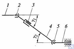
Figure 1. Diagram of a universal joint drive: 1, 4, 6 — driveshafts; 2, 5 — universal joints; 3 — compensating connection; u1, u2 — angles between shafts
Općenito, pogon univerzalnog zgloba sastoji se od univerzalnih zglobova 2 i 5, pogonskih vratila 1, 4 i 6 te kompenzacijskog spoja 3. Ponekad je pogonsko vratilo ugrađeno na međunosač pričvršćen na poprečni nosač okvira vozila. Univerzalni zglobovi osiguravaju prijenos momenta između vratila čije se osi sijeku pod kutom. Univerzalni zglobovi dijele se na nejednolike i zglobove konstantne brzine. Zglobovi nejednolike brzine dalje se klasificiraju na elastične i krute. Zglobovi konstantne brzine mogu biti kuglasti s razdjelnim žljebovima, kuglasti s razdjelnom polugom i bregasti. Obično se ugrađuju u pogon vodećih upravljanih kotača, gdje kut između vratila može doseći 45°, a središte univerzalnog zgloba mora se podudarati s točkom presjeka osi rotacije kotača i njegove osi okretanja.
Elastični univerzalni zglobovi prenose moment između osovina s osima koje se sijeku pod kutom od 2...3° zbog elastične deformacije spojnih elemenata. Kruti zglob nejednolike brzine prenosi moment s jedne osovine na drugu putem pomičnog spoja krutih dijelova. Sastoji se od dva jarma – 3 i 5, u čije cilindrične rupe su na ležajevima ugrađeni krajevi A, B, V i G spojnog elementa – križa 4. Jarmovi su kruto spojeni s osovinama 1 i 2. Jaram 5 može se okretati oko osi BG križa i istovremeno se, zajedno s križem, okretati oko osi AV, čime se omogućuje prijenos rotacije s jedne osovine na drugu s promjenjivim kutom između njih.
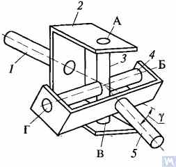
Figure 2. Diagram of a rigid non-uniform velocity universal joint
If shaft 7 rotates around its axis by an angle α, then shaft 2 will rotate by an angle β over the same period. The relationship between the rotation angles of shafts 7 and 2 is determined by the expression tanα = tanβ * cosγ, gdje je γ kut pod kojim su postavljene osi vratila. Ovaj izraz pokazuje da je kut β ponekad manji, jednak ili veći od kuta α. Jednakost tih kutova javlja se svakih 90° rotacije vratila 7. Stoga, kod jednolike rotacije vratila 1, kutna brzina vratila 2 nije jednolika i mijenja se prema sinusoidnom zakonu. Nejednolikost rotacije vratila 2 postaje značajnija kako se povećava kut γ između osi vratila.
If the non-uniform rotation of shaft 2 is transmitted to the shafts of the units, additional pulsating loads will occur in the transmission, increasing with the angle γ. To prevent the non-uniform rotation of shaft 2 from being transmitted to the unit shafts, two universal joints are used in the universal joint drive. They are installed so that the angles γ1 and γ2 are equal; the forks of the universal joints, fixed on the non-uniformly rotating shaft 4, should be positioned in the same plane.
Dizajn glavnih dijelova kardanskih zglobnih pogona prikazan je na slici 3. Kardanski zglob s nejednolikom brzinom sastoji se od dva jarma (1) spojena križem (3). Jedan od jarmova ponekad ima prirubnicu, dok je drugi zavaren na cijev pogonskog vratila ili ima užljebljeni kraj (6) (ili čahuru) za spajanje na pogonsko vratilo. Zglobovi križa ugrađeni su u ušice oba jarma na igličastim ležajevima (7). Svaki ležaj smješten je u kućištu (2) i pričvršćen je u ušici jarma poklopcem koji je pričvršćen na jaram s dva vijka osigurana jezičcima na podlošci. U nekim slučajevima ležajevi su u jaramovima pričvršćeni uskočnim prstenovima. Za zadržavanje podmazivanja u ležaju i zaštitu od vode i prljavštine, nalazi se gumena samozatezna brtva. Unutarnja šupljina križa ispunjena je mašću kroz maznicu, koja dopire do ležajeva. Križ obično ima sigurnosni ventil za zaštitu brtve od oštećenja zbog tlaka masti koja se pumpa u križ. Zupčasti spoj (6) podmazuje se pomoću mazalice (5).
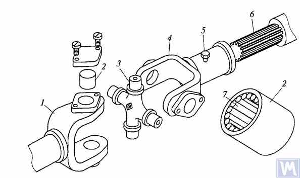
Figure 3. Details of a rigid non-uniform velocity universal joint
Maksimalni kut između osi vratila spojenih krutim univerzalnim zglobovima s nejednolikom brzinom obično ne prelazi 20°, jer se učinkovitost značajno smanjuje pri većim kutovima. Ako se kut između osi vratila mijenja unutar 0...2%, zglobovi križa se deformiraju igličastim ležajevima, što uzrokuje brzi otkaz univerzalnog zgloba.
U mjenjačima brzih gusjeničnih vozila često se koriste univerzalni zglobovi s tipovima zupčastih spojnica, koji omogućuju prijenos momenta između osovina s osima koje se sijeku pod kutovima do 1,5...2°.
Driveshafts are typically made tubular, using special steel seamless or welded tubes. The yokes of the universal joints, splined sleeves, or tips are welded to the tubes. To reduce the transverse loads acting on the driveshaft, dynamic balancing is performed with the universal joints assembled. Imbalance is corrected by welding balancing plates to the driveshaft or sometimes by installing balancing plates under the bearing caps of the universal joints. The relative position of the splined connection parts after assembly and balancing of the universal joint drive at the factory is usually marked with special labels.
The compensating connection of the universal joint drive is usually made in the form of a splined connection, allowing axial movement of the universal joint drive parts. It consists of a splined tip that fits into the splined sleeve of the universal joint drive. Lubrication is introduced into the splined connection through a grease fitting or applied during assembly and replaced after prolonged use of the vehicle. A seal and a cover are typically installed to prevent grease leakage and contamination.
For long driveshafts, intermediate supports are usually used in universal joint drives. An intermediate support typically consists of a bracket bolted to the vehicle frame cross member, in which a ball bearing is mounted in a rubber elastic ring. The bearing is sealed on both sides with caps and has a lubrication device. The elastic rubber ring helps to compensate for assembly inaccuracies and bearing misalignment that may occur due to frame deformations.
A universal joint with needle bearings (Figure 4a) consists of yokes, a cross, needle bearings, and seals. The cups with needle bearings are fitted onto the trunnions of the cross and sealed with seals. The cups are secured in the yokes with snap rings or caps fastened with screws. Universal joints are lubricated through a grease fitting via internal drillings in the cross. A safety valve is used to eliminate excess oil pressure in the joint. During uniform rotation of the driving yoke, the driven yoke rotates non-uniformly: it advances and lags behind the driving yoke twice per revolution. To eliminate non-uniform rotation and reduce inertial loads, two universal joints are used.
In the drive to the front driving wheels, constant velocity universal joints are installed. The constant velocity joint drive of GAZ-66 and ZIL-131 vehicles consists of yokes 2, 5 (Figure 4b), four balls 7, and a central ball 8. The driving yoke 2 is integral with the inner axle shaft, while the driven yoke is forged together with the outer axle shaft, at the end of which the wheel hub is fixed. The driving moment from yoke 2 to yoke 5 is transmitted through balls 7, which move along circular grooves in the yokes. The central ball 8 serves to center the yokes and is held in place by studs 3, 4. The rotation frequency of yokes 2, 5 is the same due to the symmetry of the mechanism relative to the yokes. The change in shaft length is ensured by the free splined connections of the yokes with the shaft.
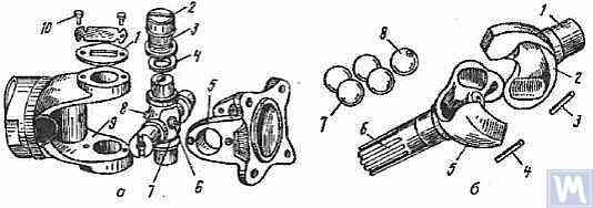
Figure 4. Universal Joints: a — universal joint: 1 — cap; 2 — cup; 3 — needle bearing; 4 — seal; 5, 9 — yokes; 6 — safety valve; 7 — cross; 8 — grease fitting; 10 — screw; b — constant velocity universal joint: 1 — inner axle shaft; 2 — driving yoke; 3, 4 — studs; 5 — driven yoke; 6 — outer axle shaft; 7 — balls; 8 — central ball
2. Universal Joint Drive Malfunctions
Universal joint drive malfunctions typically manifest as sharp knocks in the universal joints that occur when the vehicle is moving, especially during shifts between gears and sudden increases in the engine crankshaft speed (for example, when transitioning from engine braking to acceleration). A sign of universal joint malfunction can be its heating to a high temperature (over 100°C). This happens due to significant wear of the bushings and trunnions of the universal joint, needle bearings, crosses, and splined connections, resulting in misalignment of the universal joint and significant impact axial loads on the needle bearings. Damage to the cork seals of the universal joint cross leads to rapid wear of the trunnion and its bearing.
During maintenance, the universal joint drive is checked by sharply rotating the driveshaft by hand in both directions. The degree of free rotation of the shaft determines the wear of the universal joints and splined connections. Every 8-10 thousand kilometers, the condition of the bolted connections of the driven shaft flanges of the gearbox and the drive shaft of the main transmission gear with the flanges of the end universal joints and the fastening of the intermediate support of the driveshaft are checked. The condition of the rubber boots on the splined connections and the cork seals of the universal joint cross is also checked. All fastening bolts must be tightened fully (tightening torque 8-10 kgf·m).
Needle bearings of the universal joints are lubricated with liquid oil used for transmission units; splined connections in most vehicles are lubricated with greases (US-1, US-2, 1-13, etc.); the use of grease for lubricating needle bearings is strictly prohibited. In some vehicles, splined connections are lubricated with transmission oil. The intermediate support bearing, mounted in a rubber sleeve, practically does not require lubrication, as it is lubricated during assembly at the factory. The support bearing of the ZIL-130 vehicle is lubricated with grease through a pressure fitting during regular maintenance (every 1100-1700 km).
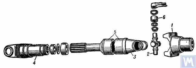
Figure 5. Universal joint drive: 1 — flange for securing the driveshaft; 2 — universal joint cross; 3 — universal joint yoke; 4 — sliding yoke; 5 — driveshaft tube; 6 — needle roller bearing with closed end
The universal joint drive consists of two universal joints with needle bearings, connected by a hollow shaft, and a sliding yoke with involute splines. To ensure reliable protection from dirt and provide good lubrication of the splined connection, the sliding yoke (6), connected to the secondary shaft (2) of the gearbox, is placed in an extension (1) attached to the gearbox housing. Additionally, this location of the splined connection (outside the zone between the joints) significantly increases the stiffness of the universal joint drive and reduces the likelihood of shaft vibrations when the sliding splined connection wears out.
Pogonsko vratilo izrađeno je od tankostijene električno zavarene cijevi (8), u koju su na svakom kraju utisnuta dva identična jarma (9), a zatim zavarena elektrolučnim zavarivanjem. Kućišta igličastih ležajeva (18) križa (25) utisnuta su u ušice jarmova (9) i osigurana su opružnim prstenovima (20). Svaki ležaj univerzalnog zgloba sadrži 22 igle (21). Utisnute kapice (24) utisnute su na izbočene zupce križa, u koje su ugrađeni prstenovi od pluta (23). Ležajevi se podmazuju pomoću kutne mazalice (17) uvrnute u navojni otvor u središtu križa, spojene na prolazne kanale u zupcima križa. Na suprotnoj strani križa univerzalnog zgloba, u njegovom središtu nalazi se sigurnosni ventil (16), dizajniran za ispuštanje viška masti prilikom punjenja križa i ležajeva te za sprječavanje nakupljanja tlaka unutar križa tijekom rada (ventil se aktivira pri tlaku od oko 3,5 kg/cm²). Nužnost ugradnje sigurnosnog ventila proizlazi iz činjenice da pretjerani porast tlaka unutar križa može dovesti do oštećenja (ekstruzije) plutenih brtvi.
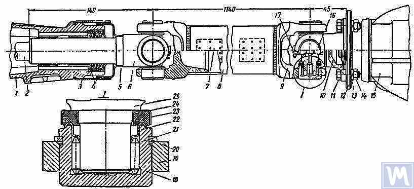
Figure 6. Driveshaft Assembly: 1 — gearbox extension; 2 — secondary shaft of the gearbox; 3 and 5 — dirt deflectors; 4 — rubber seals; 6 — sliding yoke; 7 — balancing plate; 8 — driveshaft tube; 9 — yoke; 10 — flange yoke; 11 — bolt; 12 — flange of the rear axle drive gear; 13 — spring washer; 14 — nut; 15 — rear axle; 16 — safety valve; 17 — angular grease fitting; 18 — needle bearing; 19 — yoke eye; 20 — spring retaining ring; 21 — needle; 22 — washer with toroidal end; 23 — cork ring; 24 — stamped cap; 25 — cross
Pogonsko vratilo, sastavljeno s oba univerzalna zgloba, pažljivo je dinamički uravnoteženo na oba kraja zavarivanjem balansirajućih ploča (7) na cijev. Stoga se prilikom rastavljanja vratila svi njegovi dijelovi moraju pažljivo označiti kako bi se mogli ponovno sastaviti u izvorne položaje. Nepoštivanje ove upute narušava ravnotežu vratila, uzrokujući vibracije koje mogu oštetiti mjenjač i karoseriju vozila. Ako se pojedini dijelovi istroše, posebno ako se cijev savije zbog udara i postane nemoguće dinamički uravnotežiti vratilo nakon sastavljanja, mora se zamijeniti cijelo vratilo.
Possible Driveshaft Malfunctions, Their Causes, and Solutions
| Cause of Malfunction | Solution |
|---|---|
| Driveshaft Vibration | |
| 1. Shaft bending due to an obstacle | 1. Straighten and dynamically balance the assembled shaft or replace the assembled shaft |
| 2. Bearing and cross wear | 2. Replace bearings and crosses and dynamically balance the assembled shaft |
| 3. Wear of extension bushings and sliding yoke | 3. Replace the extension and sliding yoke and dynamically balance the assembled shaft |
| Knocks When Starting and Coasting | |
| 1. Wear of sliding yoke splines or secondary gearbox shaft | 1. Replace worn parts. When replacing the sliding yoke, dynamically balance the assembled shaft |
| 2. Loose bolts securing the flange yoke to the rear axle drive gear flange | 2. Tighten bolts |
| Oil Throwing from Universal Joint Seals | |
| Wear of cork rings in universal joint seals | Replace cork rings, maintaining the relative position of all driveshaft parts during reassembly. If there is wear on crosses and bearings, replace the bearings and crosses and dynamically balance the assembled shaft |
3. Driveshaft Balancing
After repairing and assembling the driveshaft, it is dynamically balanced on a machine. One design of a balancing machine is shown in Figure 7. The machine consists of a plate (18), a pendulum frame (8) mounted on four vertical elastic rods (3), ensuring its oscillation in the horizontal plane. A bracket and front headstock (9), secured on a bracket (4), are mounted on the longitudinal tubes of the pendulum frame (8). The rear headstock (6) is on a movable traverse (5), allowing dynamic balancing of driveshafts of different lengths. The headstock spindles are mounted on precision ball bearings. The spindle of the front headstock (9) is driven by an electric motor installed in the machine base, through a V-belt drive and an intermediate shaft, on which a limb (10) (graduated disk) is mounted. Additionally, two stands (15) with retractable locking pins (17) are installed on the machine plate (18), ensuring the fixation of the front and rear ends of the pendulum frame depending on the balancing of the front or rear end of the driveshaft.
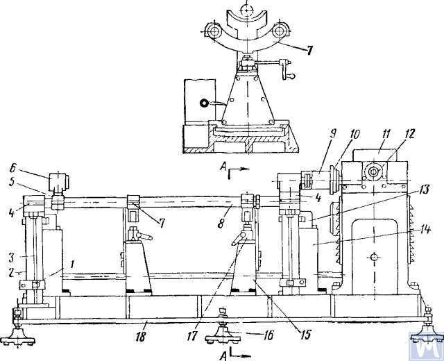
Figure 7. Dynamic Balancing Machine for Driveshafts
1—clamp; 2—dampers; 3—elastic rod; 4—bracket; 5—movable traverse; 6—rear headstock; 7—crossbar; 8—pendulum frame; 9—front driving headstock; 10—limb-disk; 11—millivoltmeter; 12—limb of the commutator-rectifier shaft; 13—magnetoelectric sensor; 14—fixed stand; 15—fixator stand; 16—support; 17—fixator; 18—support plate
The fixed stands (14) are mounted at the rear of the machine plate, and magnetoelectric sensors (13) are installed on them, with rods connected to the ends of the pendulum frame. To prevent resonance vibrations of the frame, dampers (2) filled with oil are installed under the brackets (4).
Tijekom dinamičkog balansiranja, sklop pogonskog vratila s kliznim jarmom se postavlja i pričvršćuje na stroj. Jedan kraj pogonskog vratila spojen je prirubnicom-jarmom na prirubnicu prednjeg pogonskog vretena, a drugi kraj potpornim vratom kliznog jarma na užljebljenu čahuru stražnjeg vretena. Zatim se provjerava lakoća okretanja pogonskog vratila, a jedan kraj okvira njihala stroja se fiksira pomoću fiksatora. Nakon pokretanja stroja, grana ispravljača se okreće suprotno od kazaljke na satu, dovodeći iglu milivoltmetra do maksimalnog očitanja. Očitavanje milivoltmetra odgovara veličini neravnoteže. Skala milivoltmetra graduirana je u gram-centimetrima ili gramima protuutega. Nastavkom okretanja grane ispravljača u smjeru suprotnom od kazaljke na satu, očitanje milivoltmetra se dovodi na nulu i stroj se zaustavlja. Na temelju očitanja grane ispravljača određuje se kutni pomak (kut pomaka neravnoteže), a ručnim okretanjem pogonskog vratila ta se vrijednost postavlja na međugranu vratila. Mjesto zavarivanja balansirajuće ploče bit će na vrhu pogonskog vratila, a uteženi dio na dnu u korekcijskoj ravnini. Zatim se balansirajuća ploča pričvršćuje i veže tankom žicom na udaljenosti od 10 mm od zavara, pokreće se stroj i provjerava se ravnoteža kraja pogonskog vratila s pločom. Neravnoteža ne smije biti veća od 70 g cm. Zatim se, otpuštanjem jednog kraja i pričvršćivanjem drugog kraja okvira njihala stalkom za fiksiranje, izvodi dinamičko balansiranje drugog kraja pogonskog vratila prema gore opisanom tehnološkom slijedu.
Driveshafts have some balancing features. For most parts, the base for dynamic balancing is the support necks (e.g., rotors of electric motors, turbines, spindles, crankshafts, etc.), but for driveshafts, it is the flanges. During assembly, there are unavoidable gaps in different connections leading to imbalance. If the minimum imbalance cannot be achieved during balancing, the shaft is rejected. The accuracy of balancing is influenced by the following factors:
- Gap in the connection between the landing belt of the driveshaft flange and the inner hole of the clamping flange of the left and right support headstocks;
- Radial and end runout of the base surfaces of the flange;
- Praznine u šarnirima i žljebnim spojevima. Prisutnost masti u šupljini žljebnog spoja može dovesti do "lebdeće" neravnoteže. Ako to sprječava postizanje potrebne točnosti balansiranja, pogonsko vratilo se balansira bez masti.
Some imbalances may be completely uncorrectable. If increased friction is observed in the universal joints of the driveshaft, the mutual influence of the correction planes increases. This leads to a decrease in the performance and accuracy of balancing.
Prema OST 37.001.053-74, utvrđeni su sljedeći standardi neravnoteže: pogonska vratila s dva zgloba (dvostruka) dinamički se balansiraju, a s tri (trostruka) - sastavljena s međunosačem; prirubnice (jarmovi) pogonskih vratila i spojnica težine veće od 5 kg statički se balansiraju prije sastavljanja vratila ili spojnice; norme preostale neravnoteže za pogonska vratila na svakom kraju ili na međunosaču trozglobnih pogonskih vratila procjenjuju se specifičnom neravnotežom;
Najveća dopuštena specifična norma preostale neravnoteže na svakom kraju osovine ili na međuosloncu, kao i za trozglobna pogonska vratila u bilo kojem položaju na balansirajućem postolju, ne smije prelaziti: za mjenjače osobnih automobila i kamiona malih tereta (do 1 t) i vrlo malih autobusa – 6 g-cm/kg, za ostale – 10 g-cm/kg. Najveća dopuštena norma preostale neravnoteže pogonskog vratila ili trozglobnog pogonskog vratila treba se osigurati na balansirajućem postolju pri frekvenciji vrtnje koja odgovara njihovim frekvencijama u mjenjaču pri najvećoj brzini vozila.
Za kardanska vratila i trozglobna kardanska vratila kamiona nosivosti 4 t i više, malih i velikih autobusa, dopušteno je smanjenje frekvencije vrtnje na balansirajućem stalku na 70% frekvencije vrtnje prijenosnih vratila pri maksimalnoj brzini vozila. Prema OST 37.001.053-74, frekvencija vrtnje balansirajućih kardanskih vratila treba biti jednaka:
nb = (0,7 ... 1,0) nr,
where nb – frekvencija rotacije za uravnoteženje (treba odgovarati glavnim tehničkim podacima stalka, n=3000 min-1-1; nr – maksimalna radna frekvencija rotacije, min-1.
In practice, due to the gap in the joints and splined connections, the driveshaft cannot be balanced at the recommended rotation frequency. In this case, another rotation frequency is chosen, at which it balances.
4. Modern Balancing Machines for Driveshafts
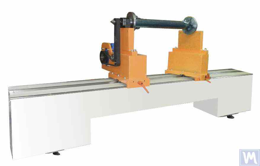
Figure 8. Balancing Machine for Driveshafts up to 2 Meters Long, Weighing up to 500 kg
The model has 2 stands and allows balancing in 2 correction planes.
Balancing Machine for Driveshafts up to 4200 mm Long, Weighing up to 400 kg
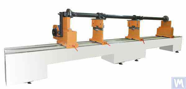
Figure 9. Balancing Machine for Driveshafts up to 4200 mm Long, Weighing up to 400 kg
The model has 4 stands and allows balancing in 4 correction planes simultaneously.
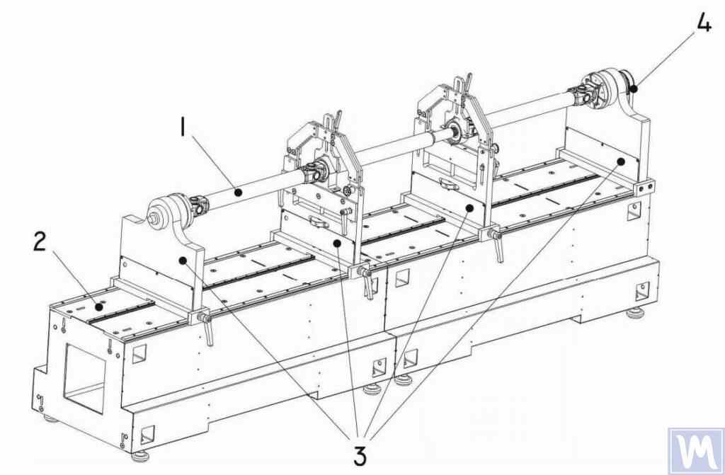
Figure 10. Horizontal Hard Bearing Balancing Machine for Dynamic Balancing of Driveshafts
1 – Balancing item (driveshaft); 2 – Machine base; 3 – Machine supports; 4 – Machine drive; The structural elements of the machine supports are shown in Figure 9.
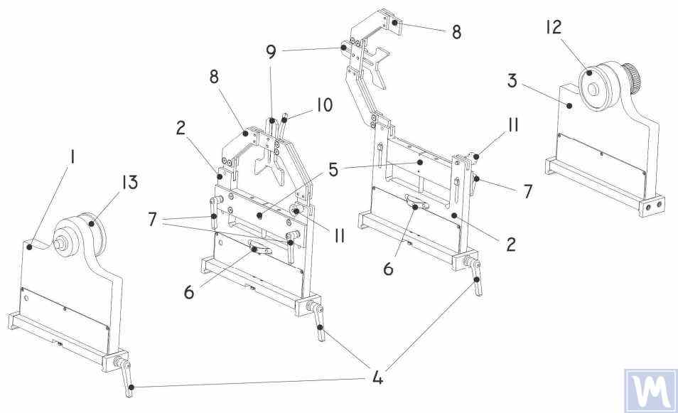
Figure 11. Machine Support Elements for Dynamic Balancing of Driveshafts
1 – Left non-adjustable support; 2 – Intermediate adjustable support (2 pcs.); 3 – Right non-adjustable fixed support; 4 – Support frame lock handle; 5 – Movable support platform; 6 – Support vertical adjustment nut; 7 – Vertical position lock handles; 8 – Support clamping bracket; 9 – Intermediate bearing movable clamp; 10 – Clamp lock handle; 11 – Clamping bracket lock; 12 – Drive (leading) spindle for item installation; 13 – Driven spindle
5. Preparation for Driveshaft Balancing
Below, we will consider the setup of the machine supports and the installation of the balancing item (four-support driveshaft) on the machine supports.
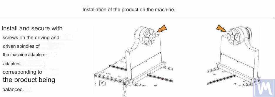
Figure 12. Installation of Transitional Flanges on the Spindles of the Balancing Machine
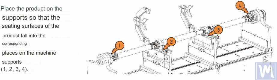
Figure 13. Installation of the Driveshaft on the Supports of the Balancing Machine
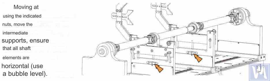
Figure 14. Leveling the Driveshaft Horizontally on the Supports of the Balancing Machine Using a Bubble Level
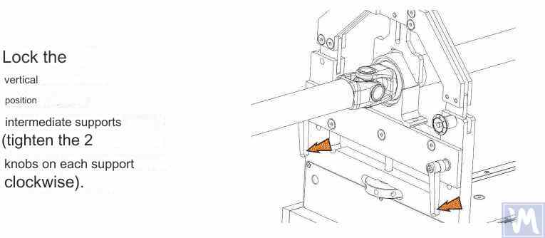
Figure 15. Fixing the Intermediate Supports of the Balancing Machine to Prevent Vertical Displacement of the Driveshaft
Rotate the item manually for a full turn. Ensure that it rotates freely and without jamming on the supports. After this, the mechanical part of the machine is set up, and the item installation is complete.
6. Driveshaft Balancing Procedure
The process of driveshaft balancing on the balancing machine will be considered using the Balanset-4 measuring system as an example. The Balanset-4 is a portable balancing kit designed for balancing in one, two, three, and four correction planes of rotors, either rotating in their own bearings or mounted on a balancing machine. The device includes up to four vibration sensors, a phase angle sensor, a four-channel measuring unit, and a portable computer.
The entire balancing process, including measurement, processing, and display of information on the magnitude and location of corrective weights, is performed automatically and does not require the user to have additional skills and knowledge beyond the provided instructions. The results of all balancing operations are saved in the Balancing Archive and can be printed as reports if necessary. In addition to balancing, the Balanset-4 can also be used as a regular vibro-tachometer, allowing measurement on four channels of the root mean square (RMS) value of total vibration, RMS of the rotational component of vibration, and control of rotor rotation frequency.
Furthermore, the device allows displaying graphs of the time function and vibration spectrum by vibration velocity, which can be useful in assessing the technical condition of the balanced machine.

Figure 16. External View of the Balanset-4 Device for Use as a Measuring and Computing System of the Driveshaft Balancing Machine
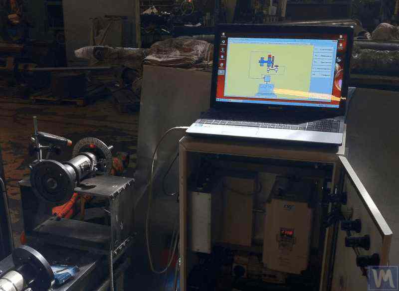
Figure 17. Example of Using the Balanset-4 Device as a Measuring and Computing System of the Driveshaft Balancing Machine
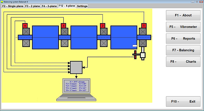
Figure 18. User Interface of the Balanset-4 Device
Uređaj Balanset-4 može biti opremljen s dvije vrste senzora – akcelerometrima vibracija za mjerenje vibracija (ubrzanje vibracija) i senzorima sile. Senzori vibracija koriste se za rad na strojevima za balansiranje nakon rezonancije, dok se senzori sile koriste za strojeve prije rezonancije.
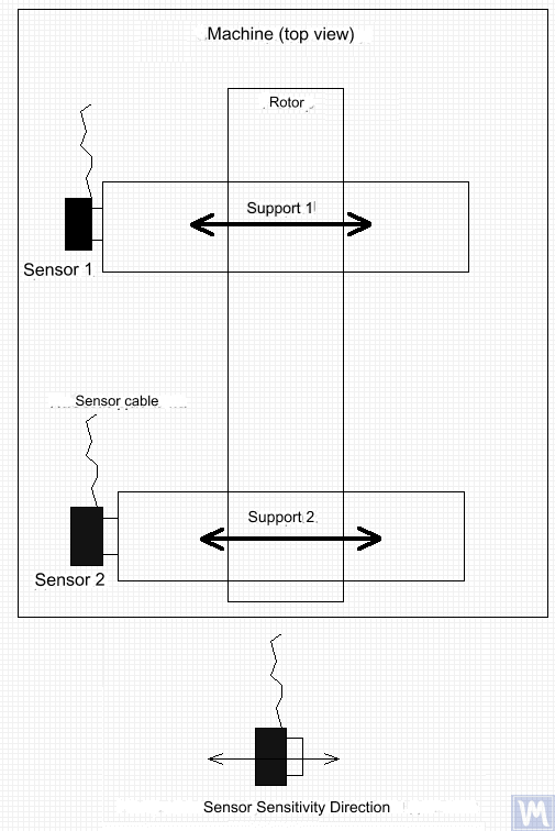
Figure 19. Installation of Balanset-4 Vibration Sensors on the Supports of the Balancing Machine
Smjer osi osjetljivosti senzora trebao bi odgovarati smjeru pomaka vibracija nosača, u ovom slučaju - horizontalnom. Za dodatne informacije o ugradnji senzora pogledajte BALANSIRANJE ROTORA U RADNIM UVJETIMA. Ugradnja senzora sile ovisi o konstrukcijskim značajkama stroja.
- Install vibration sensors 1, 2, 3, 4 on the supports of the balancing machine.
- Connect the vibration sensors to connectors X1, X2, X3, X4.
- Install the phase angle sensor (laser tachometer) 5 so that the nominal gap between the radial (or end) surface of the balanced rotor and the sensor housing is in the range of 10 to 300 mm.
- Attach a reflective tape mark with a width of at least 10-15 mm to the rotor surface.
- Connect the phase angle sensor to connector X5.
- Connect the measuring unit to the computer’s USB port.
- When using mains power, connect the computer to the power supply unit.
- Connect the power supply unit to a 220 V, 50 Hz network.
- Turn on the computer and select the “BalCom-4” program.
- Press the “F12-four-plane” button (or the F12 function key on the computer keyboard) to select the mode for measuring vibration simultaneously in four planes using vibration sensors 1, 2, 3, 4, connected respectively to inputs X1, X2, X3, and X4 of the measuring unit.
- A mnemonic diagram illustrating the process of measuring vibration simultaneously on four measurement channels (or the process of balancing in four planes) appears on the computer display, as shown in Figure 16.
Before performing balancing, it is recommended to take measurements in the vibrometer mode (F5 button).
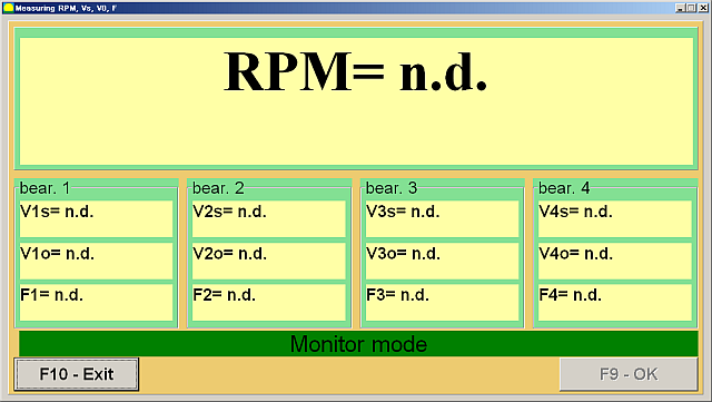
Figure 20. Vibrometer Mode Measurements
Ako ukupna magnituda vibracija V1s (V2s) približno odgovara magnitudi rotacijske komponente V1o (V2o), može se pretpostaviti da je glavni doprinos vibracijama mehanizma posljedica neravnoteže rotora. Ako ukupna magnituda vibracija V1s (V2s) značajno premašuje rotacijsku komponentu V1o (V2o), preporučuje se pregled mehanizma - provjera stanja ležajeva, osiguranje sigurne montaže na temelj, provjera da rotor ne dodiruje nepokretne dijelove tijekom rotacije i razmatranje utjecaja vibracija drugih mehanizama itd.
Proučavanje grafova vremenskih funkcija i vibracijskih spektara dobivenih u načinu rada "Grafovi-Spektralna analiza" ovdje može biti korisno.
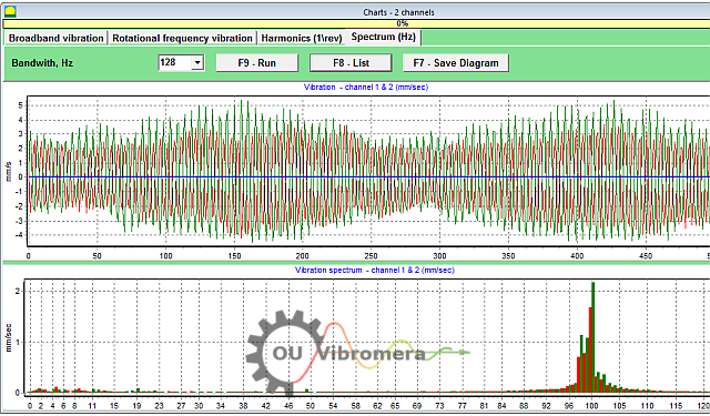
Figure 21. Vibration Time Function and Spectrum Graphs
Grafikon prikazuje na kojim su frekvencijama razine vibracija najviše. Ako se te frekvencije razlikuju od frekvencije rotacije rotora uravnoteženog mehanizma, potrebno je identificirati izvore tih komponenti vibracija i poduzeti mjere za njihovo uklanjanje prije uravnoteženja.
It is also important to pay attention to the stability of the readings in vibrometer mode – the amplitude and phase of the vibration should not change by more than 10-15% during measurement. Otherwise, the mechanism might be operating near a resonance region. In this case, the rotor speed should be adjusted.
Prilikom izvođenja balansiranja u četiri ravnine u načinu rada "Primarno", potrebno je pet kalibracijskih vožnji i barem jedna verifikacijska vožnja balansiranog stroja. Mjerenje vibracija tijekom prve vožnje stroja bez probnog utega provodi se u radnom prostoru "Balansiranje u četiri ravnine". Naknadne vožnje izvode se s probnim utegom, sekvencijalno postavljenim na pogonsko vratilo u svakoj korekcijskoj ravnini (u području svakog nosača balansirajućeg stroja).
Before each subsequent run, the following steps should be taken:
- Zaustavite rotaciju rotora uravnoteženog stroja.
- Remove the previously installed trial weight.
- Install the trial weight in the next plane.
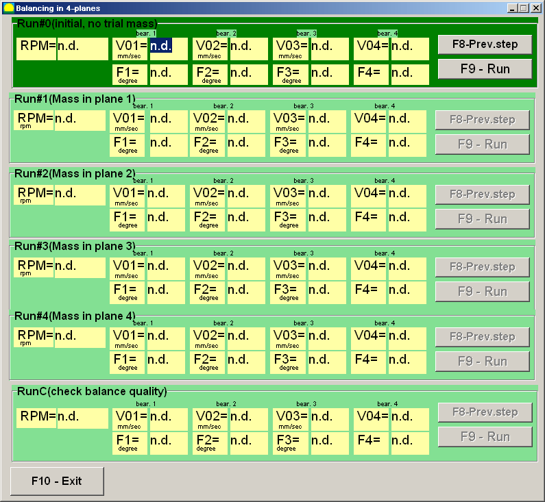
Figure 23. Four-Plane Balancing Workspace
Nakon završetka svakog mjerenja, rezultati frekvencije vrtnje rotora (Nob), as well as the RMS values (Vo1, Vo2, Vo3, Vo4) and the phases (F1, F2, F3, F4) vibracija na frekvenciji rotacije uravnoteženog rotora spremaju se u odgovarajuća polja u prozoru programa. Nakon petog pokretanja (Težina u ravnini 4), pojavljuje se radni prostor "Utezi za uravnoteženje" (vidi sliku 24) koji prikazuje izračunate vrijednosti masa (M1, M2, M3, M4) and the installation angles (f1, f2, f3, f4) of the corrective weights that need to be installed on the rotor in four planes to compensate for its imbalance.
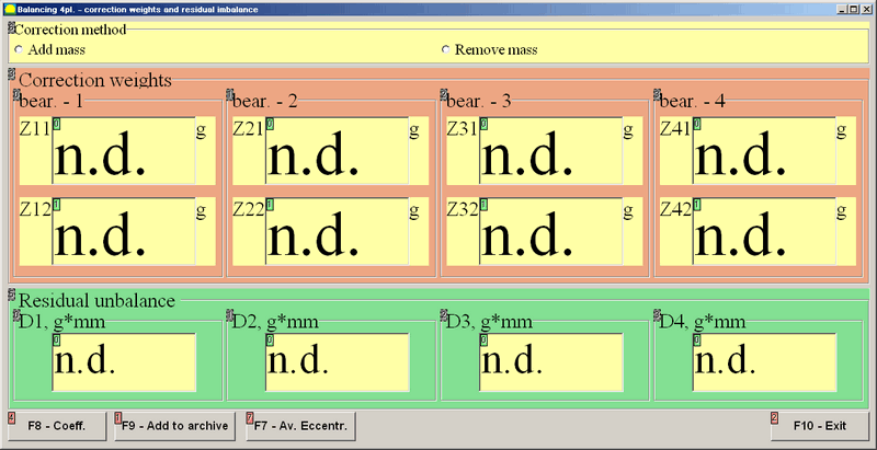
Figure 24. Workspace with Calculated Parameters of Corrective Weights in Four Planes
Attention! Nakon završetka postupka mjerenja tijekom petog pokretanja uravnoteženog stroja, potrebno je zaustaviti rotaciju rotora i ukloniti prethodno postavljeni probni uteg. Tek nakon toga možete nastaviti s postavljanjem (ili uklanjanjem) korektivnih utega na rotor.
Kutni položaj za dodavanje (ili uklanjanje) korektivnog utega na rotoru u polarnom koordinatnom sustavu mjeri se od mjesta ugradnje probnog utega. Smjer mjerenja kuta podudara se sa smjerom rotacije rotora. U slučaju balansiranja lopaticama, lopatica uravnoteženog rotora koja se uvjetno smatra prvom lopaticom podudara se s mjestom ugradnje probnog utega. Smjer numeriranja lopatica prikazan na zaslonu računala prati smjer rotacije rotora.
U ovoj verziji programa, prema zadanim postavkama pretpostavlja se da će korektivni uteg biti dodan rotoru. To je naznačeno oznakom postavljenom u polju "Dodaj". Ako je potrebno ispraviti neravnotežu uklanjanjem utega (npr. bušenjem), postavite oznaku u polje "Ukloni" pomoću miša, nakon čega će se kutni položaj korektivnog utega automatski promijeniti za 180 stupnjeva.
Nakon postavljanja korektivnih utega na uravnoteženi rotor, pritisnite tipku "Izlaz – F10" (ili funkcijsku tipku F10 na tipkovnici računala) za povratak na prethodni radni prostor "Balansiranje u četiri ravnine" i provjeru učinkovitosti operacije balansiranja. Nakon završetka provjere, rezultati frekvencije vrtnje rotora (Nob) and the RMS values (Vo1, Vo2, Vo3, Vo4) and phases (F1, F2, F3, F4) vibracija na frekvenciji vrtnje uravnoteženog rotora se spremaju. Istovremeno se radni prostor "Uravnotežavanje utega" (vidi sliku 21) pojavljuje iznad radnog prostora "Uravnoteženje u četiri ravnine", prikazujući izračunate parametre dodatnih korektivnih utega koje je potrebno ugraditi (ili ukloniti) na rotor kako bi se kompenzirala njegova preostala neravnoteža. Osim toga, ovaj radni prostor prikazuje vrijednosti preostale neravnoteže postignute nakon balansiranja. Ako vrijednosti preostale vibracije i/ili preostale neravnoteže uravnoteženog rotora zadovoljavaju zahtjeve tolerancije navedene u tehničkoj dokumentaciji, proces balansiranja može se dovršiti. U suprotnom, proces balansiranja može se nastaviti. Ova metoda omogućuje ispravljanje mogućih pogrešaka putem uzastopnih aproksimacija koje se mogu pojaviti prilikom ugradnje (uklanjanja) korektivne utege na uravnoteženom rotoru.
Ako se proces balansiranja nastavi, na balansirani rotor potrebno je ugraditi (ili ukloniti) dodatne korektivne utege prema parametrima navedenim u radnom prostoru "Balansirni utezi".
Tipka "Koeficijenti – F8" (ili funkcijska tipka F8 na tipkovnici računala) koristi se za pregled i spremanje u memoriju računala koeficijenata uravnoteženja rotora (koeficijenata dinamičkog utjecaja) izračunatih iz rezultata pet kalibracijskih ciklusa.
7. Recommended Balancing Accuracy Classes for Rigid Rotors
Table 2. Recommended Balancing Accuracy Classes for Rigid Rotors.

Recommended Balancing Accuracy Classes for Rigid Rotors
| Types of Machines (Rotors) | Balancing Accuracy Class | Value eper Ω mm/s |
|---|---|---|
| Drive crankshafts (structurally unbalanced) for large low-speed marine diesel engines (piston speed less than 9 m/s) | G 4000 | 4000 |
| Drive crankshafts (structurally balanced) for large low-speed marine diesel engines (piston speed less than 9 m/s) | G 1600 | 1600 |
| Drive crankshafts (structurally unbalanced) on vibration isolators | G 630 | 630 |
| Drive crankshafts (structurally unbalanced) on rigid supports | G 250 | 250 |
| Reciprocating engines assembled for passenger cars, trucks, and locomotives | G 100 | 100 |
| Automobile parts: wheels, wheel rims, wheelsets, transmissions | ||
| Drive crankshafts (structurally balanced) on vibration isolators | G 40 | 40 |
| Agricultural machines | G 16 | 16 |
| Drive crankshafts (balanced) on rigid supports | ||
| Crushers | ||
| Drive shafts (driveshafts, screw shafts) | ||
| Aircraft gas turbines | G 6.3 | 6.3 |
| Centrifuges (separators, settlers) | ||
| Electric motors and generators (with a shaft height of at least 80 mm) with a maximum nominal rotation speed of up to 950 min-1 | ||
| Electric motors with a shaft height of less than 80 mm | ||
| Fans | ||
| Gear drives | ||
| General-purpose machines | ||
| Metal cutting machines | ||
| Papermaking machines | ||
| Pumps | ||
| Turbochargers | ||
| Water turbines | ||
| Compressors | ||
| Computer-controlled drives | G 2.5 | 2.5 |
| Electric motors and generators (with a shaft height of at least 80 mm) with a maximum nominal rotation speed over 950 min-1 | ||
| Gas and steam turbines | ||
| Metal cutting machine drives | ||
| Textile machines | ||
| Audio and video equipment drives | G 1 | 1 |
| Grinding machine drives | ||
| Spindles and drives of high-precision equipment | G 0.4 | 0.4 |
Često postavljana pitanja o balansiranju pogonskog vratila
Što je balansiranje pogonskog vratila?
Balansiranje pogonskog vratila je proces ispravljanja bilo kakve neravnoteže mase u pogonskom vratilu kako bi se ono glatko okretalo bez uzrokovanja vibracija. To uključuje mjerenje gdje je vratilo teže na jednoj strani, a zatim dodavanje ili uklanjanje malih količina težine (na primjer, zavarivanje utega za balansiranje) kako bi se suprotstavilo toj neravnoteži. Uravnoteženo pogonsko vratilo radi ravnomjerno, što sprječava prekomjerne vibracije i trošenje komponenti vozila.
Zašto je važno balansiranje pogonskog vratila?
Neuravnotežena pogonska osovina može dovesti do jakih vibracija, posebno pri određenim brzinama, i može uzrokovati zvukove lupanja tijekom ubrzanja ili mijenjanja brzina. Vremenom te vibracije mogu oštetiti ležajeve, univerzalne zglobove i druge komponente pogonskog sklopa. Balansiranje pogonske osovine uklanja te vibracije, osiguravajući glatkiju vožnju, smanjujući opterećenje dijelova i sprječavajući skupa oštećenja ili zastoje.
Koji su uobičajeni simptomi nebalansiranog pogonskog vratila?
Tipični simptomi nebalansiranog ili neispravnog pogonskog vratila uključuju primjetne vibracije ili podrhtavanje u podu vozila ili sjedalu, posebno s povećanjem brzine. Također možete čuti zvukove kucanja ili zveckanja prilikom mijenjanja brzina ili tijekom ubrzanja i usporavanja. U nekim slučajevima, kardanski zglob se može pregrijati zbog neravnoteže. Ako primijetite ove znakove, vjerojatno je potrebno balansiranje ili popravak pogonskog vratila.
Kako se balansira pogonsko vratilo?
Balansiranje pogonskog vratila obično se vrši pomoću specijaliziranog stroja za balansiranje. Pogonsko vratilo se montira i okreće velikom brzinom dok senzori detektiraju bilo kakvu neravnotežu. Tehničar zatim pričvršćuje male utege na pogonsko vratilo (ili uklanja materijal) na određenim pozicijama na temelju očitanja stroja. Ovaj se postupak ponavlja sve dok se pogonsko vratilo ne okreće bez značajnih vibracija. Moderni sustavi poput Balanset-4 mogu voditi ovaj proces i točno izračunati gdje i koliko utega treba dodati za precizno balansiranje.
Zaključak
Zaključno, pravilno balansiranje pogonskog vratila ključno je za sigurnost, performanse i uštedu troškova. Otkrivanjem i ispravljanjem neravnoteže sprječavate nepotrebno trošenje dijelova, izbjegavate štetne kvarove i održavate optimalne performanse stroja. Moderni sustavi za balansiranje poput naših uređaja Balanset-1 i Balanset-4 čine proces učinkovitim, pomažući čak i malim radionicama da postignu profesionalne rezultate.
Ako se suočavate s upornim vibracijama pogonskog vratila ili vam je potrebno pouzdano rješenje za balansiranje, ne oklijevajte djelovati. Primijenite korake navedene u ovom vodiču ili se obratite našim stručnjacima za pomoć. Uz pravi pristup i opremu, možete osigurati da vaše pogonsko vratilo radi glatko i pouzdano dugi niz godina. Kontaktirajte nas kako biste saznali više ili istražili najbolju opremu za balansiranje pogonskog vratila za vaše potrebe.

0 komentara