బ్యాలెన్సింగ్ సేవలు › Fans › అక్షసంబంధ ఫ్యాన్లు
అక్షసంబంధ ఫ్యాన్ బ్యాలెన్సింగ్ — ఆన్-సైట్లో, నడుస్తున్న వేగంతో
వేన్-యాక్సియల్, ట్యూబ్-యాక్సియల్ మరియు పెద్ద అక్షసంబంధ ప్రవాహ ఫ్యాన్లు బ్లేడ్ అరుగుదల, మురికి నిర్మాణం లేదా మరమ్మత్తు వాటి ద్రవ్యరాశి పంపిణీని మారిస్తే వెంటనే కంపనాన్ని అభివృద్ధి చేస్తాయి. మేము అక్షసంబంధ ఫ్యాన్ రోటర్లను ఆన్-సైట్లో, నడుస్తున్న వేగంతో — డక్ట్ నుండి తీసివేయకుండా, రోటర్ విడదీయకుండా — బేరింగ్ వైఫల్యం, బ్లేడ్-టిప్ రాపిడి మరియు నిర్మాణపరమైన అలసటకు మూల కారణాన్ని ఒకే ఆన్-సైట్ సెషన్లో తొలగిస్తూ.
In short: అక్షసంబంధ ఫ్యాన్ బ్యాలెన్సింగ్ ఇన్-సిటులో నిర్వహించబడుతుంది, రోటర్ డక్ట్ లోపల సాధారణ నడుస్తున్న వేగంతో పని చేస్తున్నప్పుడు, ప్రభావ గుణకం పద్ధతిని ఉపయోగించి. బేరింగ్ హౌసింగ్పై కంపన యాక్సెలెరోమీటర్ మరియు షాఫ్ట్పై లేజర్ తాఖోమీటర్ అసమతుల్య స్థితిని కొలుస్తాయి; Balanset-1A సరైన దిద్దుబాటు ద్రవ్యరాశి మరియు కోణ స్థానాన్ని లెక్కిస్తుంది. రోటర్ తీసివేయడం లేదు, రవాణా లేదు — సాధారణ పని ఒక గంటలోపు పూర్తవుతుంది, కంపనాన్ని 70 % లేదా అంతకంటే ఎక్కువ తగ్గిస్తుంది, ISO 14694 / ISO 21940-11 బ్యాలెన్స్ గ్రేడ్లను పూర్తి చేస్తుంది మరియు బేరింగ్ జీవితాన్ని ఎనిమిది లేదా అంతకంటే ఎక్కువ రెట్లు పెంచుతుంది.
మీ అక్షసంబంధ ఫ్యాన్ అసమతుల్యంగా ఉందని సూచించే లక్షణాలు
అక్షసంబంధ ఫ్యాన్ అసమతుల్యత విస్మరిస్తే క్రమంగా తీవ్రమయ్యే లక్షణాల సమితి ద్వారా వ్యక్తమవుతుంది:
యాక్సియల్ ఫ్యాన్లు సమతుల్యత కోల్పోవడానికి కారణాలు — మరియు దాని వ్యయాలు
ఒక యాక్సియల్ ఫ్యాన్ సమతుల్య సహనాల మేరలో ఫ్యాక్టరీ నుండి వెలువడుతుంది, కానీ ఫీల్డ్ సర్వీస్ వేగంగా ఆ సమతుల్యతను చెరుపుతుంది. గాలి ప్రవాహంలోని అరగదీసే కణాలు బ్లేడ్ల ముందు అంచులను అసమానంగా కోరుతాయి; కొన్ని బ్లేడ్ల పీడన ముఖంపై ధూళి మరియు పీచు పదార్థం పేరుకుపోతుంది, మిగతావాటిని శుభ్రంగా వదిలిపెడుతుంది; తుప్పు వెనుక అంచులను అసమానంగా నశింపజేస్తుంది; మరియు బ్లేడ్ మార్పిడులు లేదా వెల్డ్ మరమ్మత్తులు హబ్లో ఒక వైపు స్థానికీకరించిన ద్రవ్యరాశిని జోడిస్తాయి. కేంద్రాపసార బలం దీనికి అనుపాతంలో ఉంటుంది కాబట్టి square భ్రమణ వేగానికి, సాధారణ ఫ్యాన్ వేగాల వద్ద బ్లేడ్ చివర వద్ద 20 g ఆఫ్సెట్ కూడా వందల న్యూటన్ల డైనమిక్ బలాన్ని ఉత్పత్తి చేస్తుంది — బేరింగ్ అదనపు రేడియల్ లోడ్గా శోషించడానికి రూపకల్పన చేయబడిన దాని కంటే చాలా ఎక్కువ.
ఆర్థిక పరిణామాలు వేగంగా పేరుకుపోతాయి: రీప్లేస్మెంట్ బేరింగులు మరియు లాబిరింత్ సీళ్ళు, అనియంత్రిత మూసివేతల సమయంలో అత్యవసర కార్మిక వ్యయాలు, బ్లేడ్-టిప్ క్లియరెన్స్ మార్పుల వల్ల తగ్గిన ఫ్యాన్ సామర్థ్యం, మరియు మద్దతు ఉక్కు నిర్మాణంలో చివరికి నిర్మాణ అలసట. ఒకే ఒన్-సైట్ బ్యాలెన్సింగ్ సెషన్ — సాధారణంగా ఒక గంట కన్నా తక్కువ — పదే పదే దాని దిగువ లక్షణాలను చికిత్సించే బదులు మూల వద్దనే డైనమిక్ బలాన్ని తొలగిస్తుంది.
కంపనం సగానికి తగ్గించడం బేరింగ్ జీవితకాలాన్ని ఎందుకు రెట్టింపు చేస్తుంది
మేము యాక్సియల్ ఫ్యాన్ను ఎలా బ్యాలెన్స్ చేస్తాం — దశల వారీగా
Balanset-1A తో ఫీల్డ్ బ్యాలెన్సింగ్ ఇన్ఫ్లుయెన్స్-కోఎఫిషియంట్ పద్ధతిని అనుసరిస్తుంది — రోటర్ జ్యామితి యొక్క ముందస్తు జ్ఞానం అవసరం లేకుండా మీరు స్వయంగా ఆన్-సైట్లో నిర్వహించగల అదే క్రమపద్ధతి:
- సెన్సార్లను అమర్చండి. ఒక వైబ్రేషన్ యాక్సిలెరోమీటర్ను ఫ్యాన్ బేరింగ్ హౌసింగ్కు అమర్చారు మరియు లేజర్ టాకోమీటర్ను షాఫ్ట్ లేదా హబ్పై రిఫ్లెక్టివ్ స్ట్రిప్కు గురిపెడతారు. ఫ్యాన్ సాధారణ ఆపరేషన్ పరిస్థితులలో అంతటా నడుస్తూనే ఉంటుంది — విడదీయడం అవసరం లేదు.
- బేస్లైన్ కొలవండి. పూర్తి పనితీరు వేగంలో ఒక రన్ 1× RPM వద్ద వైబ్రేషన్ యాంప్లిట్యూడ్ మరియు ఫేజ్ యాంగిల్ను నమోదు చేస్తుంది, తద్వారా ప్రస్తుత అన్బ్యాలెన్స్ స్థితిని పరిమాణం మరియు దిశలో నిర్ణయిస్తుంది.
- ట్రయల్ వెయిట్ జోడించండి. తెలిసిన బరువు కలిగిన ఒక చిన్న ట్రయల్ వెయిట్ను నమోదిత కోణీయ స్థానంలో బ్లేడ్ రింగ్, హబ్ డిస్క్ లేదా బ్లేడ్ రూట్కు బిగించారు. రెండవ రన్ రోటర్ ఆ స్థానంలో నిర్దిష్ట ద్రవ్యరాశికి ఎలా స్పందిస్తుందో చూపిస్తుంది — ఇన్ఫ్లుయెన్స్ కోఎఫిషియంట్.
- పరికరాన్ని గణన చేయనివ్వండి. Balanset-1A ప్రభావ-గుణాంక అల్గారిథమ్ను ఉపయోగించి ఖచ్చితమైన దిద్దుబాటు ద్రవ్యరాశి మరియు కోణీయ స్థానాన్ని లెక్కిస్తుంది — సన్నని రోటర్లకు సింగిల్-ప్లేన్ బ్యాలెన్సింగ్, విస్తృత బ్లేడ్ రింగులు, పెద్ద టన్నెల్ ఫ్యాన్లు లేదా హబ్-అండ్-టిప్ కాన్ఫిగరేషన్లకు రెండు ప్లేన్లలో బ్యాలెన్సింగ్ — ఇక్కడ అన్బ్యాలెన్స్ రోటర్ అక్షం వెంట పంపిణీ అయి ఉంటుంది.
- కరెక్షన్ వెయిట్ను అమర్చండి. హబ్ డిస్క్, బ్లేడ్ రూట్ లేదా బ్యాలెన్స్ రింగ్పై సూచించిన స్థానంలో లెక్కించిన ద్రవ్యరాశిని వెల్డ్ చేయండి, బోల్ట్ చేయండి లేదా క్లాంప్ చేయండి. పరిష్కారంలో భాగమైతే తప్ప, ట్రయల్ వెయిట్ను తొలగించాలి.
- ధృవీకరించి డాక్యుమెంట్ చేయండి. తుది కొలత రన్ ద్వారా అవశేష అన్బ్యాలెన్స్ ఫ్యాన్’స్ బ్యాలెన్స్ గ్రేడ్కు సంబంధించిన ISO టాలరెన్స్ బ్యాండ్ పరిధిలో ఉందని నిర్ధారించబడుతుంది. Balanset-1A నిర్వహణ రికార్డులు మరియు కంప్లయన్స్ డాక్యుమెంటేషన్ కోసం బ్యాలెన్సింగ్ నివేదికను రూపొందిస్తుంది.
మేము ఏమి బ్యాలెన్స్ చేస్తాము
- వేన్-యాక్సియల్ ఫ్యాన్లు (డక్ట్లో అమర్చిన, గైడ్ వేన్లతో కూడిన)
- ట్యూబ్-యాక్సియల్ ఫ్యాన్లు (సిలిండ్రికల్ కేసింగ్లో ప్రొపెల్లర్)
- పెద్ద అక్షసంబంధ ప్రవాహ ఫ్యాన్లు (గని వెంటిలేషన్, సొరంగం)
- ఫోర్స్డ్-డ్రాఫ్ట్ (FD) మరియు ఇండ్యూస్డ్-డ్రాఫ్ట్ (ID) బాయిలర్ ఫ్యాన్లు
- శీతలీకరణ టవర్ ప్రొపెల్లర్ ఫ్యాన్లు
- పైకప్పు వెలికితీత ఫ్యాన్లు
- స్మోక్-ఎగ్జాస్ట్ మరియు ఫైర్-రేటెడ్ యాక్సియల్ ఫ్యాన్లు
- వేరియబుల్-పిచ్ బ్లేడ్లతో కూడిన రివర్సిబుల్ యాక్సియల్ ఫ్యాన్లు
- వ్యవసాయ ధాన్యం ఆరబెట్టే ఫ్యాన్లు
- చిన్న డక్ట్-మౌంటెడ్ ఇన్లైన్ యాక్సియల్ ఫ్యాన్లు
సహనాలు & ప్రమాణాలు
ISO 14694 పారిశ్రామిక ఫ్యాన్లకు బ్యాలెన్స్ నాణ్యత మరియు వైబ్రేషన్ పరిమితులను నిర్దేశిస్తుంది, ఫ్యాన్ అప్లికేషన్ వర్గం (BV-1 నుండి BV-5 వరకు) వారీగా అనుమతించదగిన అవశేష అన్బ్యాలెన్స్ను నిర్వచిస్తుంది. అంతర్లీన బ్యాలెన్స్-గ్రేడ్ టాలరెన్సులు నిర్వచించబడ్డాయి ISO 21940-11 (ISO 1940-1 స్థానంలో వచ్చిన వారసుడు). చాలా పారిశ్రామిక యాక్సియల్ ఫ్యాన్లు వర్గాలలో చేరుతాయి, ఇక్కడ G6.3 కనీస అంగీకారయోగ్య గ్రేడ్; క్రిటికల్ ప్రాసెస్ గాలిని నిర్వహించే, మండే ఆవిర్లను నిర్వహించే, లేదా అధిక టిప్ వేగంతో నడిచే ఫ్యాన్లు సాధారణంగా దీనిని పూర్తిచేయాల్సి ఉంటుంది G2.5 లేదా అంతకంటే మెరుగ్గా.
మీ ఫ్యాన్ వర్గం అవసరమైన గ్రేడ్కు అనుగుణంగా మేము బ్యాలెన్స్ చేస్తాము మరియు మీ నిర్వహణ మరియు కంప్లయన్స్ రికార్డుల కోసం — కొలిచిన నిర్వహణ వేగంలో g·mm లో — డాక్యుమెంట్ చేయబడిన అవశేష అన్బ్యాలెన్స్ సంఖ్యలను అందిస్తాము. మా అవశేష అసమతుల్యత కాలిక్యులేటర్ ప్రారంభించే ముందు మీ అనుమతించదగిన సహనశీలతను కనుగొనడానికి.
Balanset-1A — మీ సంపూర్ణ ఫీల్డ్-బ్యాలన్సింగ్ కిట్
ఈ పేజీలోని ప్రతిదీ ఒకే పోర్టబుల్ పరికరంతో చేయబడుతుంది: Balanset-1A. ఇది రెండు-చానెల్ డైనమిక్ బ్యాలెన్సర్ మరియు వైబ్రేషన్ అనలైజర్, ఇది యాక్సియల్ ఫ్యాన్ రోటర్లను బ్యాలెన్స్ చేస్తుంది వాటి స్వంత బేరింగులలో, నిర్వహణ వేగంలో, డక్ట్ లోపల, 3-రన్ ఇన్ఫ్లుయెన్స్ కోఎఫిషియెంట్ పద్ధతిని ఉపయోగించి — సాఫ్ట్వేర్ సరైన కరెక్షన్ మాస్ మరియు కోణాన్ని లెక్కించి రిపోర్ట్ సేవ్ చేస్తుంది.
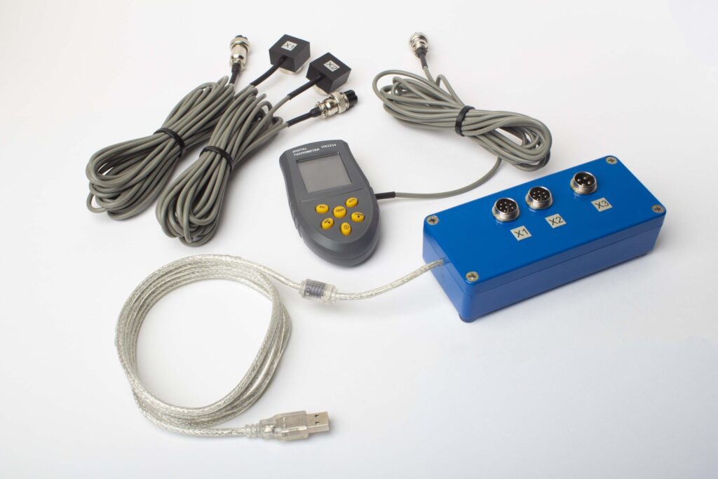
పూర్తి కిట్లో ఏముంది
€1,975 · పూర్తి కిట్, స్టాక్లో ఉంది, VAT ఇన్వాయిస్
- ఇంటర్ఫేస్ మెజర్మెంట్ యూనిట్ (USB, 2 చానెల్లు)
- రెండు వైబ్రేషన్ యాక్సెలెరోమీటర్లు (4 m కేబుల్, 10 m ఐచ్ఛికం)
- లేజర్ టాకోమీటర్ / ఆప్టికల్ ఫేజ్ సెన్సర్ (50–500 mm)
- సెన్సార్ కోసం మాగ్నెటిక్ స్టాండ్
- ట్రయల్ & కరెక్షన్ వెయిట్ల కోసం డిజిటల్ స్కేల్
- Windows బ్యాలెన్సింగ్ & అనాలిసిస్ సాఫ్ట్వేర్
- ప్లాస్టిక్ ట్రాన్స్పోర్ట్ కేస్
Full Kit
యూనిట్ · 2 సెన్సార్లు · లేజర్ టాకోమీటర్ · మాగ్నెటిక్ స్టాండ్ · డిజిటల్ స్కేల్ · సాఫ్ట్వేర్ · ట్రాన్స్పోర్ట్ కేస్. బాక్స్ తెరిచిన వెంటనే బ్యాలన్సింగ్ ప్రారంభించడానికి అవసరమైనదంతా.
OEM set
యూనిట్ · 2 సెన్సార్లు · లేజర్ టాకోమీటర్ · సాఫ్ట్వేర్. ఇప్పటికే స్టాండ్, స్కేల్ మరియు కేస్ ఉన్న ఇంటిగ్రేటర్లకు, లేదా యూనిట్ను బ్యాలన్సింగ్ మెషీన్లో పొందుపరచాలనుకున్నవారికి.
| Parameter | Value |
|---|---|
| మెజర్మెంట్ చానెల్లు | 2 (సింగిల్-ప్లేన్ & టూ-ప్లేన్ బ్యాలెన్సింగ్) |
| వైబ్రేషన్ వేగం పరిధి | 0.2–80 mm/s RMS |
| పౌనఃపున్య పరిధి | 5–1000 Hz (≤10% amplitude error above 550 Hz) |
| కొలత ఖచ్చితత్వం | పూర్తి స్కేల్లో ±5% |
| Method | 3-రన్ ఇన్ఫ్లుయెన్స్-కో఼ఎఫిషియెంట్ (1 లేదా 2 ప్లేన్లు) |
| Analysis | 1× వద్ద ఆంప్లిట్యూడ్ & ఫేజ్, FFT స్పెక్ట్రమ్ & వేవ్ఫారమ్, సేవ్ అయిన రిపోర్టులు |
| Laptop | చేర్చబడలేదు (Windows PC, అభ్యర్థన మేరకు అందుబాటులో) |
ఫీల్డ్ బాలెన్సింగ్ vs బాలెన్సింగ్ మెషిన్ — మీ ఫ్యాన్కు ఏది సరైనది?
| Factor | క్షేత్ర సమతుల్యత (Balanset-1A) | సమతుల్యత యంత్రం (వర్క్షాప్) |
|---|---|---|
| ఫ్యాన్ను డక్ట్ నుండి తొలగించారా? | లేదు — స్థానంలోనే నడుస్తుంది | అవును — పూర్తి విభజన అవసరం |
| రోటర్ విశ్లేషణ/డిసాసెంబ్లీ? | No | Yes |
| ఉత్పత్తి నిలిపివేత | సెన్సార్ అమరిక మాత్రమే (<15 నిమి) | గంటల నుండి రోజులు (తొలగించడం, రవాణా, బ్యాలెన్సింగ్, తిరిగి అమర్చడం) |
| సమతుల్యత వేగం | వాస్తవ పనిచేసే వేగం & వాయుప్రవాహం | ప్రత్యేక తక్కువ-వేగం స్పిండిల్ |
| షాఫ్ట్ వంగడం & కప్లింగులను పరిగణనలోకి తీసుకుంటుంది | అవును — పూర్తి అసెంబ్లీ ఇన్-సిటు బ్యాలెన్స్ చేయబడింది | కేవలం రోటర్ మాత్రమే, ఇన్స్టాలేషన్ ప్రభావాలు లేవు |
| వేరియబుల్-పిచ్ బ్లేడ్లు | ఎంచుకున్న ఆపరేటింగ్ పిచ్లో బాలెన్స్ చేయబడింది | స్థిర పిచ్ మాత్రమే |
| Standards met | ISO 14694, ISO 21940-11 | ISO 21940-11 |
| Equipment cost | €1,975 (పూర్తి కిట్) | €10,000 – €50,000+ |
| సాధారణ పని సమయం | సైట్లో <1 గంట | మొత్తం 1–3 రోజులు |
ఫ్యాన్ నడవగలిగినప్పుడు మరియు రోటర్ రిజిడ్-రోటర్ ప్రమాణాన్ని సంతృప్తిపరచినప్పుడు (నిర్వహణ వేగం మొదటి క్రిటికల్ స్పీడ్ కంటే చాలా తక్కువగా ఉన్నప్పుడు), ఫీల్డ్ బ్యాలెన్సింగ్ ప్రాధాన్య ఎంపిక. వర్క్షాప్ బ్యాలెన్సింగ్ మెషీన్ సున్నా రన్ టైమ్ కలిగిన కొత్త-నిర్మాణ రోటర్లకు, లేదా బ్లేడ్ తనిఖీ లేదా భర్తీ కోసం పూర్తి విడదీతలు అవసరమయ్యే చాలా పెద్ద రోటర్లకు అనుకూలంగా ఉంటుంది.
వాస్తవ యాక్సియల్-ఫ్యాన్ బాలెన్సింగ్ కేసులు
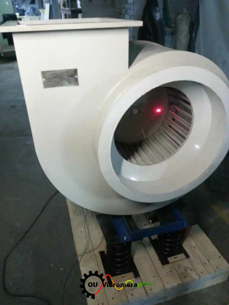
యాక్సియల్ & వేన్ ఫ్యాన్లు
డాక్యుమెంట్ చేయబడిన అవశేష అన్బ్యాలెన్స్ ఫలితాలతో పారిశ్రామిక సెట్టింగులలో యాక్సియల్ మరియు వేన్-యాక్సియల్ ఫ్యాన్ రోటర్ల ఫీల్డ్ బ్యాలెన్సింగ్.
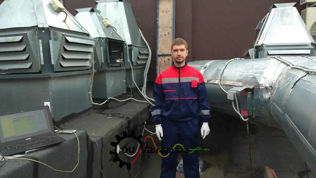
ఎగ్జాస్ట్ ఫ్యాన్ సైట్లో బ్యాలెన్సింగ్
Balanset-1A ఉపయోగించి నడుస్తున్న వేగంలో ఎగ్జాస్ట్ ఫ్యాన్ యొక్క ఆన్-సైట్ సింగిల్-ప్లేన్ బ్యాలెన్సింగ్, వైబ్రేషన్ 75 % కంటే ఎక్కువగా తగ్గించబడింది.

HVAC ఫ్యాన్ దశల వారీ మార్గదర్శి
సెన్సార్ ప్లేస్మెంట్ మరియు వెయిట్-ఫిక్సింగ్ సూచనలతో HVAC యాక్సియల్-ఫ్యాన్ ఇంపెల్లర్లకు సంపూర్ణ రెండు-ప్లేన్ బ్యాలెన్సింగ్ విధానం.
ఉచిత యాక్సియల్-ఫ్యాన్ కాలిక్యులేటర్లు
యాక్సియల్ ఫ్యాన్ బాలెన్సింగ్ FAQ
యాక్సియల్ ఫ్యాన్ను డక్ట్ నుండి తొలగించకుండా బ్యాలెన్స్ చేయవచ్చా?
వైబ్రేషన్ అన్బ్యాలెన్స్ వల్ల వస్తుందా లేదా మరో లోపం వల్ల వస్తుందా అని నేను ఎలా తెలుసుకోవాలి?
వేరియబుల్-పిచ్ యాక్సియల్ ఫ్యాన్లకు ప్రత్యేక శ్రద్ధ అవసరమా?
యాక్సియల్ ఫ్యాన్లకు ఏ ISO బ్యాలెన్స్ గ్రేడ్ వర్తిస్తుంది?
యాక్సియల్ ఫ్యాన్కు ఒక ప్లేన్ లేదా రెండు ప్లేన్లు?
Balanset-1A తో మేమే బ్యాలెన్సింగ్ చేయవచ్చా?
సిద్ధాంతం నేర్చుకోండి
మీ యాక్సియల్ ఫ్యాన్ను అక్కడే బ్యాలెన్స్ చేయండి — ఈ రోజే
Balanset-1A మీకు సింగిల్- మరియు టూ-ప్లేన్ యాక్సియల్ ఫ్యాన్ బ్యాలెన్సింగ్ను నడుస్తున్న వేగంలో, డక్ట్ లోపలే నిర్వహించడంలో మార్గనిర్దేశం చేస్తుంది, ఖచ్చితమైన కరెక్షన్ వెయిట్ మరియు కోణాన్ని లెక్కిస్తుంది, మరియు ISO 14694 మరియు ISO 21940-11 ప్రకారం సాధించిన రెసిడ్యువల్ అన్బ్యాలెన్స్ను నమోదు చేస్తుంది. రోటర్ తొలగింపు అవసరం లేదు, ఉత్పత్తి నష్టం లేదు — కేవలం నిశ్శబ్దంగా, దీర్ఘకాలం నడిచే ఫ్యాన్.
