Mga serbisyo sa pagbabalanse › Bawasan ang Vibration ng Makina
Paano Alisin ang Machine Vibration — Tukuyin, Pagkatapos Ayusin
Ang sobrang vibration sa rotating machinery ay nagpapaikli ng bearing life, sinisira ang seals, lumilikha ng cracks sa welds at nag-trigger ng unplanned shutdowns. Bago magdagdag ng balance weight, kailangan mong malaman kung ang may-sala ay imbalance, misalignment, looseness, bearing damage o resonance — bawat fault ay may natatanging frequency fingerprint. Ang pahinang ito ay nagpapakita sa iyo kung paano basahin ang fingerprint na iyon at, kapag kinonfirma na ang unbalance, kung paano ito aalisin sa pamamagitan ng field balancing sa operating speed.

In short: Upang mabawasan ang vibration sa rotating machine, una ay sukatin ang FFT spectrum upang matukoy ang dominanteng frequency. Ang peak sa eksaktong 1× RPM na may stable phase angle ay nangangahulugang imbalance — ang pinaka-karaniwang at pinaka-korektable na sanhi. Ang field balancing gamit ang Balanset-1A ay nag-attach ng vibration sensors at laser tachometer sa tumatakbong makina, nagkalkula ng eksaktong correction mass at angle sa dalawa o tatlong maikling measurement runs, at inaalis ang unbalance nang hindi inalis ang rotor mula sa mga bearings nito. Ang tipikal na trabaho ay tumatagal ng wala pang isang oras at karaniwang binabawasan ang vibration ng 70 % o higit pa, pinahabang ang bearing life ng hanggang 10×.
Tukuyin ang sanhi bago kumilos
Ang iba't ibang faults ay umiigaw sa iba't ibang frequencies at sa iba't ibang directions. Ang pagsusukat ng amplitude, phase at FFT spectrum bago ang anumang intervention ay nagsasabi sa iyo ng eksaktong kung ano ang iyong kinalabasan. Ang talahanayan sa ibaba ay isang mabilis na reference — basahin ito bago hawakan ang kahit isang bolt.
| Fault | Dominant na frequency | Direction | Key clue | First action |
|---|---|---|---|---|
| Imbalance | 1× RPM only | Radial | Phase stable; ang trial weight ay nagbabago ng amplitude & phase nang magkasama | Field balancing (tingnan sa ibaba) |
| Misalignment | 1× + malakas na 2× RPM | Axial elevated | Coupling ay mainit na tumatakbo; mataas na axial versus radial ratio | I-realign ang shaft train muna |
| Bearing damage | BPFO / BPFI / BSF (hindi-integer ng RPM) | Radial | Tumataas na pangkalahatang trend sa loob ng ilang linggo; walang koneksyon sa speed change | Palitan ang bearing, pagkatapos balancing |
| Structural looseness | 0.5×, 1×, 1.5×, 2×… (maraming harmonics) | Radial o axial | Gumagalaw sa partial-load; maingay na comb spectrum | Higpitan / ayusin ang loose element |
| Resonance | Spike malapit sa natural frequency | Variable | Phase shifts ~180° sa pamamagitan ng resonant speed | I-detune o palakasin ang structure; bawasan ang excitation sa pamamagitan ng balancing |
| Combined faults | Maraming peak, hindi matatag na phase | Mixed | Dalawa o tatlong depekto na sabay-sabay | Ayusin muna ang mga mekanikong problema; i-balanse nang huli |
Tuntunin ng hinlalaki: kung ang 1× RPM component ay may mahigit 80 % ng kabuuang vibration energy at ang phase angle ay mauulit sa loob ng ±5°, ang imbalance ay ang pangunahing dahilan at ang field balancing ay ang tamang susunod na hakbang. Kung ang ibang frequencies ay makabuluhan, ayusin muna ang mga ito o ang balance correction ay maglilipat sa susunod na maintenance stop.
Pagkilala sa imbalance — ang pinakamadalas at malusog na dahilan
Ang imbalance ay responsable sa karamihan ng vibration complaints sa rotating equipment. Ito ang mga katangian nito:
Bakit nangyari ang imbalance — at ano ang halaga nito
Bawat rotor ay umaalis sa factory na may maliit na residual unbalance — isang maliit na mass asymmetry na ang ISO 21940-11 grades ay dinisenyo upang kontrolin. Sa serbisyo, ang balance na iyon ay nagbabago: erosion at cavitation attack impeller vanes nang hindi pantay, fouling at scale magsama-sama nang hindi simetriko sa fan blades, ang welded repair o replacement vane ay nagdadagdag ng asymmetric mass, at ang thermal distortion sa panahon ng start-up o shutdown ay nakabaluktot ng shaft centre lines.
Dahil ang centrifugal force ay nag-iikot ayon sa square ng rotational speed, ilang gramo ng offset sa 750 rpm ay nagiging tens ng kilonewtons ng shaking force sa 3,000 rpm. Ang cyclic radial load na ito ay nakakapagod sa rolling-element bearings, nag-aalis ng mechanical seals, bumabali ng grout at nag-aalas ng hold-down bolts — na pagkatapos ay naglulunsad ng looseness at palakasin ang bawat ibang vibration source. Ang isang unplanned shutdown na dulot ng cascading vibration damage ay karaniwang nagkakahalaga ng mas marami sa lost production at emergency labour kaysa sa isang one-hour field-balancing job.
Bakit ang pag-kalahati ng vibration ay nagpaparami ng buhay ng bearing
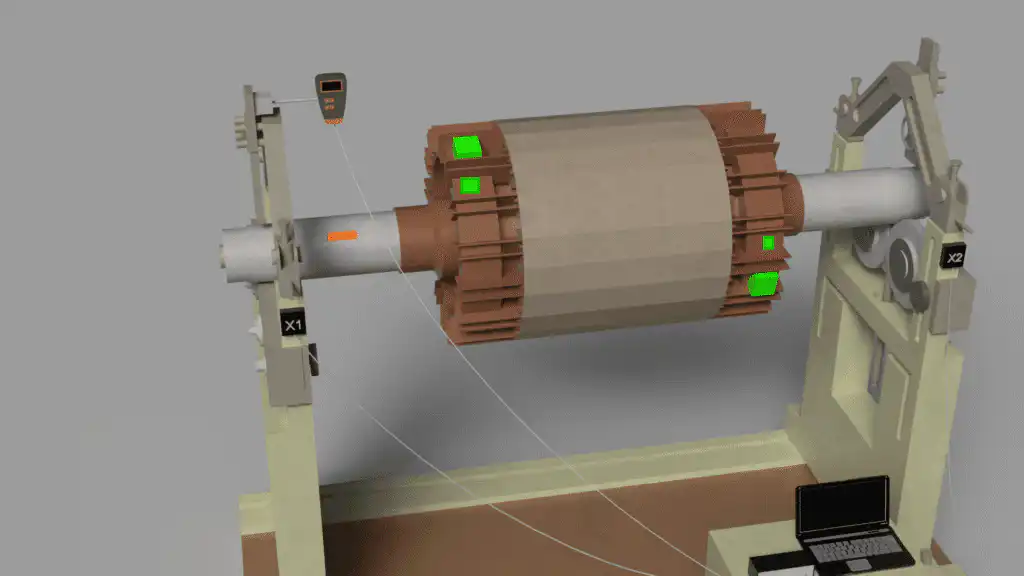
Paano alisin ang vibration sa pamamagitan ng field balancing — hakbang sa hakbang
Sundin ang diagnostic sequence na ito gamit ang Balanset-1A bago magmit sa anumang partikular na fix. Ang paglalaktaw ng mga hakbang ay ang pinakamadalas na dahilan kung bakit ang balancing ay “hindi gumagana”:
- Sukatin ang baseline vibration. Itala ang kabuuang antas (mm/s RMS), ang amplitude at phase ng 1× RPM component, at ang kumpletong FFT spectrum. Ito ay nagsasabi sa iyo kung ang pangunahing enerhiya ay nasa 1× (imbalance) o sa ibang mga frequency (iba pang mga depekto). Huwag magpatuloy sa balancing kung ang 1× ay hindi nangunguna.
- Lutasin muna ang mga mekanikong pabala. Inspeksyunan ang mga luwag na hold-down bolts, mga nabusog na bearing housings, shaft misalignment at malinaw na mechanical damage. Higpitan, ihanay at palitan kung kinakailangan, pagkatapos ay sumusukat ulit. Ang mga mechanical defects ay nakakasira sa influence-coefficient calculations.
- Kumpirmahin ang imbalance gamit ang trial weight. Magkabit ng kilalang trial mass sa rotor sa isang napiling angular position at magpatakbo ulit. Ang isang malinaw na pagbabago sa amplitude at phase sa 1× ay nagpapatunay na ang rotor ay tumutugon sa mass correction — ikaw ay nakikipag-ugnayan sa imbalance, hindi sa iba.
- Hayaan ang device na kalkulahin ang correction. Ang Balanset-1A ay gumagamit ng influence-coefficient algorithm upang makalkula ang eksaktong correction mass at angular position para sa isang o dalawang planes. Ikabit ang correction weight (weld, bolt o clip) sa kinalkuiang anggulo.
- Suriin laban sa ISO 20816. Ang isang final measurement run ay nagpapatunay na ang residual vibration ay nasa loob ng ISO 20816 acceptance zone para sa machine class at ang residual unbalance ay nasa loob ng ISO 21940-11 G-grade tolerance. Ang Balanset-1A ay nagsasave ng documented report.
Equipment na aming binabantayan upang mabawasan ang vibration
- Industrial fan impellers at centrifugal blowers
- Pump rotors at centrifugal impellers
- Electric motor rotors at generator rotors
- Compressor impellers at screw-compressor rotors
- Driveshafts at cardan shafts
- Combine-harvester at agricultural machine drums
- Process rolls, drums at cylinders
- CNC spindles at toolholders
- Turbine rotors at turbocharger impellers
- Crushers, separators at centrifuge rotors
- Anumang rigid rotor na maaaring ligtas na patakbuhin na may sensors at trial weights na nakakabit
Vibration standards & balance tolerances
ISO 20816 (and its predecessor ISO 10816) defines vibration-severity evaluation zones A–D measured on non-rotating parts at operating speed. Zone A is new-machine quality; Zone D means shut down immediately. The zone boundaries depend on machine group, power and support flexibility — for example, for medium machines (15–300 kW, Group 2) on rigid supports the Zone B/C boundary is 2.8 mm/s RMS, while for large machines (>300 kW, Group 1) on rigid supports it is 4.5 mm/s RMS. Select the applicable group and support class from the standard before judging severity; do not apply one generic limit to all machines.
ISO 21940-11 (dating ISO 1940-1) ay tumutukoy ng residual-unbalance G-grades mula sa G0.4 (precision grinding spindles) hanggang G40 (agricultural drives). Common industrial targets: fans at blowers G6.3, pumps at compressors G2.5, electric motors G2.5–G1.0, precision spindles G1.0 o mas mahigpit. Kami ay nagsasagawa ng balancing sa grade na tinukoy ng iyong equipment manufacturer at nagbibigay ng documented residual-unbalance figures sa balancing report. Gamitin ang aming calculator ng residual imbalance upang mahanap ang inyong pinahihintulutang tolerance bago magsimula.
| Equipment type | Typical G-grade | G value = eper × ω (mm/s) |
|---|---|---|
| Precision grinding spindles, gyroscopes | G0.4 | 0.4 mm/s |
| Gas-turbine rotors, turbochargers | G1.0–G2.5 | 1–2.5 mm/s |
| Centrifugal pump impellers, electric motors | G2.5 | 2.5 mm/s |
| Industrial fans, blowers, centrifuges | G6.3 | 6.3 mm/s |
| Mga roller, drum, pangkalahatang makinarya | G6.3–G16 | 6.3–16 mm/s |
| Agricultural at off-road machinery | G16–G40 | 16–40 mm/s |
Note: the G number itself is the product eper × ω in mm/s. The permissible residual specific unbalance depends on service speed: eper [g·mm/kg] = 9549 × G / n, with n in rpm — e.g. G6.3 at 3000 rpm gives eper ≈ 20 g·mm/kg.
Ang Balanset-1A — ang iyong kumpletong field-balancing kit
Lahat ng nasa pahinang ito ay ginagawa gamit ang isang portable na instrumento: ang Balanset-1A. Ito ay isang two-channel dynamic balancer at vibration analyzer na nagbalancing ng anumang rigid rotor sa sarili nitong bearings, sa operating speed, gamit ang 3-run influence-coefficient na pamamaraan — kinakalkula ng software ang eksaktong correction mass at anggulo at nagse-save ng ulat.
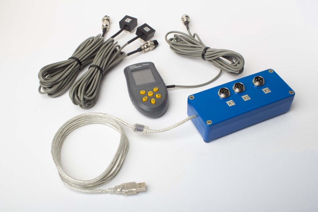
Ano ang Nasa Buong Kit
€1,975 · Buong Kit, available sa stock, VAT invoice
- Yunit ng interfase para sa pagsusukat (USB, 2 channel)
- Dalawang accelerometer ng vibrasyon (4 m cable, 10 m opsyonal)
- Laser tachometer / optical phase sensor (50–500 mm)
- Magnetic stand para sa sensor
- Digital na timbangan para sa trial & correction weights
- Windows balancing & analysis software
- Plastic na transport case
Full Kit
Unit · 2 sensor · laser tachometer · magnetic stand · digital na timbangan · software · transport case. Lahat ng kailangan upang magsimulang mag-balance mula sa kahon.
OEM set
Unit · 2 sensor · laser tachometer · software. Para sa mga integrator na mayroon nang stand, timbangan at case, o na nag-e-embed ng unit sa isang balancing machine.
| Parameter | Value |
|---|---|
| Channel ng pagsusukat | 2 (single- & two-plane balancing) |
| Saklaw ng vibration velocity | 0.2–80 mm/s RMS |
| Saklaw ng dalas | 5–1000 Hz (≤10% amplitude error above 550 Hz) |
| Katumpakan ng pagsusukat | ±5% ng buong sukat |
| Method | 3-run na koepisyente ng impluwensya (1 o 2 mga panukat) |
| Analysis | Amplitude at yugto sa 1×, FFT na spektro at waveform, nakaligtas na mga ulat |
| Laptop | Hindi kasama (Windows PC, available sa kahilingan) |
Tunay na mga kaso ng pagbabawas ng vibration
Kapag ang balancing ay hindi nakakatulong
Systematic diagnosis ng isang machine kung saan ang balance corrections ay nabigong mabawasan ang vibration — at kung ano ang aktwal na cause.

Gaano kadalas na dapat suriin
Inirerekomendang vibration monitoring intervals para sa iba't ibang machine types at operating environments.
Gabay sa field balancing
Teorya, kasanayan at paglutas ng problema para sa field rotor balancing gamit ang Balanset-1A instrument.
Libreng vibration & balancing calculators
Vibration reduction FAQ
Na-balance ko ang rotor ngunit ang makina ay patuloy na gumagalaw — bakit?
Paano ko malalaman kung ang problema ay unbalance o misalignment?
Maaari ba akong magbalanse ng makina na may bearing damage din?
Anong vibration level ang katanggap-tanggap ayon sa ISO 20816?
Gaano kadalas dapat kong suriin ang vibration at ibalanse ang rotating equipment?
Paano kung ang vibration ay bumalik na malapit pagkatapos ng balancing?
Matuto ng teorya
Diagnostikuhin ang sira — pagkatapos alisin ito
Ang Balanset-1A ay sumusukat ng amplitude ng vibration, phase at ang buong FFT spectrum upang maaari mong kumpirmahin ang root cause bago mag-commit sa isang correction, pagkatapos ay nag-balance ng anumang rigid rotor sa sariling bearings nito sa operating speed at nag-document ng resulta ayon sa ISO 20816 at ISO 21940-11.
