ਬੈਲੇਂਸਿੰਗ ਸੇਵਾਵਾਂ › ਮਸ਼ੀਨ ਦੀ ਵਾਈਬ੍ਰੇਸ਼ਨ ਘਟਾਓ
ਮਸ਼ੀਨ ਦੀ ਵਾਈਬ੍ਰੇਸ਼ਨ ਕਿਵੇਂ ਖ਼ਤਮ ਕਰੀਏ — ਪਹਿਲਾਂ ਨਿਦਾਨ, ਫਿਰ ਹੱਲ
ਘੁੰਮਣ ਵਾਲੀ ਮਸ਼ੀਨਰੀ ਵਿੱਚ ਬਹੁਤ ਜ਼ਿਆਦਾ ਵਾਈਬ੍ਰੇਸ਼ਨ ਬੇਅਰਿੰਗ ਦੀ ਉਮਰ ਘਟਾਉਂਦੀ ਹੈ, ਸੀਲਾਂ ਨੂੰ ਖ਼ਰਾਬ ਕਰਦੀ ਹੈ, ਵੈਲਡਾਂ ਵਿੱਚ ਦਰਾੜਾਂ ਪਾਉਂਦੀ ਹੈ ਅਤੇ ਅਚਾਨਕ ਬੰਦ ਹੋਣ ਦਾ ਕਾਰਨ ਬਣਦੀ ਹੈ। ਬੈਲੈਂਸ ਵੇਟ ਜੋੜਨ ਤੋਂ ਪਹਿਲਾਂ, ਤੁਹਾਨੂੰ ਇਹ ਜਾਣਨ ਦੀ ਲੋੜ ਹੈ ਕਿ ਕਾਰਨ ਹੈ ਅਨਬੈਲੈਂਸ, ਮਿਸਅਲਾਈਨਮੈਂਟ, ਢਿੱਲਾਪਨ, ਬੇਅਰਿੰਗ ਨੁਕਸਾਨ ਜਾਂ ਰੈਜ਼ੋਨੈਂਸ — ਹਰੇਕ ਨੁਕਸ ਦੀ ਆਪਣੀ ਵੱਖਰੀ ਫ੍ਰੀਕੁਐਂਸੀ ਪਛਾਣ ਹੁੰਦੀ ਹੈ। ਇਹ ਪੰਨਾ ਤੁਹਾਨੂੰ ਦਿਖਾਉਂਦਾ ਹੈ ਕਿ ਉਸ ਪਛਾਣ ਨੂੰ ਕਿਵੇਂ ਪੜ੍ਹਨਾ ਹੈ ਅਤੇ, ਇੱਕ ਵਾਰ ਅਨਬੈਲੈਂਸ ਦੀ ਪੁਸ਼ਟੀ ਹੋ ਜਾਣ ਤੇ, ਓਪਰੇਟਿੰਗ ਸਪੀਡ ਤੇ ਫੀਲਡ ਬੈਲੈਂਸਿੰਗ ਰਾਹੀਂ ਇਸਨੂੰ ਕਿਵੇਂ ਖ਼ਤਮ ਕਰਨਾ ਹੈ।

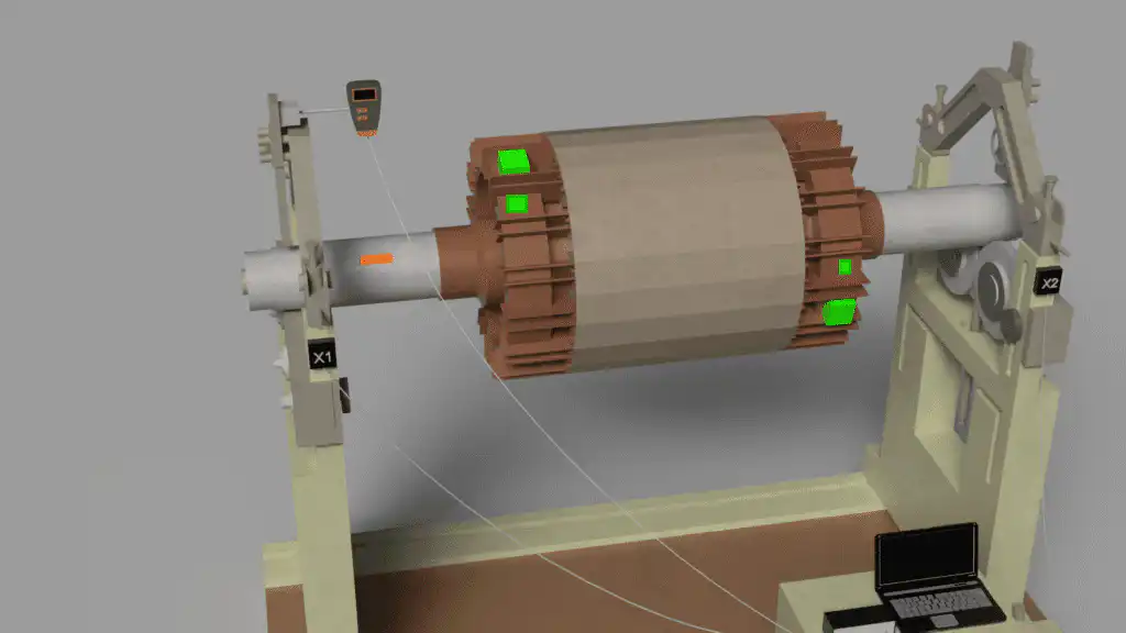
ਸੰਖੇਪ ਵਿੱਚ: ਘੁੰਮਣ ਵਾਲੀ ਮਸ਼ੀਨ ਵਿੱਚ ਵਾਈਬ੍ਰੇਸ਼ਨ ਘਟਾਉਣ ਲਈ, ਪਹਿਲਾਂ ਪ੍ਰਧਾਨ ਫ੍ਰੀਕੁਐਂਸੀ ਦੀ ਪਛਾਣ ਕਰਨ ਲਈ FFT ਸਪੈਕਟ੍ਰਮ ਮਾਪੋ। ਇੱਕ ਸਥਿਰ ਫੇਜ਼ ਐਂਗਲ ਨਾਲ ਠੀਕ 1× RPM ਤੇ ਸਿਖਰ ਦਾ ਮਤਲਬ ਹੈ ਅਨਬੈਲੈਂਸ — ਸਭ ਤੋਂ ਆਮ ਅਤੇ ਸਭ ਤੋਂ ਵੱਧ ਠੀਕ ਕੀਤੇ ਜਾ ਸਕਣ ਵਾਲਾ ਕਾਰਨ। Balanset-1A ਨਾਲ ਫੀਲਡ ਬੈਲੈਂਸਿੰਗ ਚੱਲ ਰਹੀ ਮਸ਼ੀਨ ਤੇ ਵਾਈਬ੍ਰੇਸ਼ਨ ਸੈਂਸਰ ਅਤੇ ਇੱਕ ਲੇਜ਼ਰ ਟੈਕੋਮੀਟਰ ਲਗਾਉਂਦੀ ਹੈ, ਦੋ ਜਾਂ ਤਿੰਨ ਛੋਟੀਆਂ ਮਾਪ ਦੌੜਾਂ ਵਿੱਚ ਸਹੀ ਸੁਧਾਰ ਪੁੰਜ ਅਤੇ ਐਂਗਲ ਦੀ ਗਣਨਾ ਕਰਦੀ ਹੈ, ਅਤੇ ਰੋਟਰ ਨੂੰ ਇਸਦੇ ਬੇਅਰਿੰਗਾਂ ਤੋਂ ਹਟਾਏ ਬਿਨਾਂ ਅਨਬੈਲੈਂਸ ਨੂੰ ਖ਼ਤਮ ਕਰਦੀ ਹੈ। ਇੱਕ ਆਮ ਕੰਮ ਇੱਕ ਘੰਟੇ ਤੋਂ ਘੱਟ ਸਮਾਂ ਲੈਂਦਾ ਹੈ ਅਤੇ ਆਮ ਤੌਰ ਤੇ ਵਾਈਬ੍ਰੇਸ਼ਨ ਨੂੰ 70 % ਜਾਂ ਵੱਧ ਘਟਾਉਂਦਾ ਹੈ, ਬੇਅਰਿੰਗ ਦੀ ਉਮਰ ਨੂੰ 10× ਤੱਕ ਵਧਾਉਂਦਾ ਹੈ।
ਕਾਰਵਾਈ ਕਰਨ ਤੋਂ ਪਹਿਲਾਂ ਕਾਰਨ ਦਾ ਨਿਦਾਨ ਕਰੋ
ਵੱਖ-ਵੱਖ ਨੁਕਸ ਵੱਖ-ਵੱਖ ਫ੍ਰੀਕੁਐਂਸੀ ਅਤੇ ਵੱਖ-ਵੱਖ ਦਿਸ਼ਾਵਾਂ ਵਿੱਚ ਵਾਈਬ੍ਰੇਟ ਹੁੰਦੇ ਹਨ। ਕਿਸੇ ਵੀ ਦਖਲਅੰਦਾਜ਼ੀ ਤੋਂ ਪਹਿਲਾਂ ਐਂਪਲੀਟਿਊਡ, ਫੇਜ਼ ਅਤੇ FFT ਸਪੈਕਟ੍ਰਮ ਮਾਪਣਾ ਤੁਹਾਨੂੰ ਬਿਲਕੁਲ ਦੱਸਦਾ ਹੈ ਕਿ ਤੁਸੀਂ ਕਿਸ ਨਾਲ ਨਜਿੱਠ ਰਹੇ ਹੋ। ਹੇਠਾਂ ਦਿੱਤੀ ਸਾਰਣੀ ਇੱਕ ਤੁਰੰਤ ਹਵਾਲਾ ਹੈ — ਕੋਈ ਵੀ ਬੋਲਟ ਛੂਹਣ ਤੋਂ ਪਹਿਲਾਂ ਇਸਨੂੰ ਪੜ੍ਹੋ।
| ਨੁਕਸ | ਪ੍ਰਧਾਨ ਫ੍ਰੀਕੁਐਂਸੀ | ਦਿਸ਼ਾ | ਮੁੱਖ ਸੰਕੇਤ | ਪਹਿਲੀ ਕਾਰਵਾਈ |
|---|---|---|---|---|
| ਇਮਬੈਲੈਂਸ (ਅਸੰਤੁਲਨ) | ਸਿਰਫ਼ 1× RPM | ਰੇਡੀਅਲ | ਫੇਜ਼ ਸਥਿਰ; ਟ੍ਰਾਇਲ ਵੇਟ ਐਂਪਲੀਟਿਊਡ ਅਤੇ ਫੇਜ਼ ਦੋਵਾਂ ਨੂੰ ਇਕੱਠੇ ਬਦਲਦਾ ਹੈ | ਫੀਲਡ ਬੈਲੈਂਸ (ਹੇਠਾਂ ਦੇਖੋ) |
| ਮਿਸਅਲਾਈਨਮੈਂਟ | 1× + ਮਜ਼ਬੂਤ 2× RPM | ਐਕਸੀਅਲ ਵਧਿਆ ਹੋਇਆ | ਕਪਲਿੰਗ ਗਰਮ ਚੱਲਦੀ ਹੈ; ਉੱਚ ਐਕਸੀਅਲ ਬਨਾਮ ਰੇਡੀਅਲ ਅਨੁਪਾਤ | ਪਹਿਲਾਂ ਸ਼ਾਫਟ ਟ੍ਰੇਨ ਨੂੰ ਦੁਬਾਰਾ ਇਕਸਾਰ ਕਰੋ |
| ਬੇਅਰਿੰਗ ਨੁਕਸਾਨ | BPFO / BPFI / BSF (RPM ਦਾ ਗੈਰ-ਪੂਰਨ ਅੰਕ) | ਰੇਡੀਅਲ | ਹਫ਼ਤਿਆਂ ਵਿੱਚ ਵਧ ਰਿਹਾ ਸਮੁੱਚਾ ਰੁਝਾਨ; ਸਪੀਡ ਤਬਦੀਲੀ ਨਾਲ ਕੋਈ ਸਬੰਧ ਨਹੀਂ | ਬੇਅਰਿੰਗ ਬਦਲੋ, ਫਿਰ ਬੈਲੈਂਸ ਕਰੋ |
| ਢਾਂਚਾਗਤ ਢਿੱਲ | 0.5×, 1×, 1.5×, 2×… (ਕਈ ਹਾਰਮੋਨਿਕਸ) | ਰੇਡੀਅਲ ਜਾਂ ਐਕਸੀਅਲ | ਅੰਸ਼ਕ-ਲੋਡ ਤੇ ਖੜਖੜਾਹਟ; ਸ਼ੋਰ ਵਾਲਾ ਕੰਘੀ ਸਪੈਕਟ੍ਰਮ | ਢਿੱਲੇ ਹਿੱਸੇ ਨੂੰ ਕੱਸੋ / ਮੁਰੰਮਤ ਕਰੋ |
| ਰੈਜ਼ੋਨੈਂਸ (ਗੂੰਜ) | ਕੁਦਰਤੀ ਫ੍ਰੀਕੁਐਂਸੀ ਦੇ ਨੇੜੇ ਸਿਖਰ | ਵੇਰੀਏਬਲ | ਰੈਜ਼ੋਨੈਂਟ ਸਪੀਡ ਦੌਰਾਨ ਫੇਜ਼ ~180° ਸ਼ਿਫਟ ਹੁੰਦਾ ਹੈ | ਢਾਂਚੇ ਨੂੰ ਡੀਟਿਊਨ ਜਾਂ ਸਖ਼ਤ ਕਰੋ; ਬੈਲੈਂਸਿੰਗ ਰਾਹੀਂ ਉਤੇਜਨਾ ਘਟਾਓ |
| ਮਿਸ਼ਰਿਤ ਨੁਕਸ | ਕਈ ਸਿਖਰ, ਅਸਥਿਰ ਫੇਜ਼ | ਮਿਸ਼ਰਿਤ | ਇੱਕੋ ਸਮੇਂ ਦੋ ਜਾਂ ਤਿੰਨ ਨੁਕਸ ਮੌਜੂਦ | ਪਹਿਲਾਂ ਮਕੈਨੀਕਲ ਸਮੱਸਿਆਵਾਂ ਠੀਕ ਕਰੋ; ਬੈਲੈਂਸ ਆਖਰ ਵਿੱਚ ਕਰੋ |
ਅੰਗੂਠੇ ਦਾ ਨਿਯਮ: ਜੇਕਰ 1× RPM ਕੰਪੋਨੈਂਟ ਕੁੱਲ ਵਾਈਬ੍ਰੇਸ਼ਨ ਊਰਜਾ ਦਾ 80 % ਤੋਂ ਵੱਧ ਲੈ ਕੇ ਜਾਂਦਾ ਹੈ ਅਤੇ ਫੇਜ਼ ਐਂਗਲ ±5° ਦੇ ਅੰਦਰ ਦੁਹਰਾਉਣਯੋਗ ਹੈ, ਤਾਂ ਅਨਬੈਲੈਂਸ ਪ੍ਰਧਾਨ ਕਾਰਨ ਹੈ ਅਤੇ ਫੀਲਡ ਬੈਲੈਂਸਿੰਗ ਅਗਲਾ ਸਹੀ ਕਦਮ ਹੈ। ਜੇਕਰ ਹੋਰ ਫ੍ਰੀਕੁਐਂਸੀਆਂ ਮਹੱਤਵਪੂਰਨ ਹਨ, ਤਾਂ ਪਹਿਲਾਂ ਉਹਨਾਂ ਨੂੰ ਹੱਲ ਕਰੋ ਨਹੀਂ ਤਾਂ ਬੈਲੈਂਸ ਸੁਧਾਰ ਅਗਲੇ ਮੇਨਟੇਨੈਂਸ ਸਟਾਪ ਤੇ ਬਦਲ ਜਾਵੇਗਾ।
ਅਨਬੈਲੈਂਸ ਦੀ ਪਛਾਣ — ਸਭ ਤੋਂ ਆਮ ਅਤੇ ਠੀਕ ਕੀਤੇ ਜਾ ਸਕਣ ਵਾਲਾ ਕਾਰਨ
ਘੁੰਮਣ ਵਾਲੇ ਉਪਕਰਣਾਂ ਤੇ ਵਾਈਬ੍ਰੇਸ਼ਨ ਦੀਆਂ ਜ਼ਿਆਦਾਤਰ ਸ਼ਿਕਾਇਤਾਂ ਲਈ ਅਨਬੈਲੈਂਸ ਜ਼ਿੰਮੇਵਾਰ ਹੈ। ਇਹ ਇਸਦੇ ਵਿਸ਼ੇਸ਼ ਲੱਛਣ ਹਨ:
ਅਸੰਤੁਲਨ ਕਿਉਂ ਹੁੰਦਾ ਹੈ — ਅਤੇ ਇਸਦੀ ਕੀ ਕੀਮਤ ਚੁਕਾਉਣੀ ਪੈਂਦੀ ਹੈ
ਹਰੇਕ ਰੋਟਰ ਫੈਕਟਰੀ ਤੋਂ ਇੱਕ ਛੋਟੇ ਬਚੇ ਹੋਏ ਅਸੰਤੁਲਨ — ਪੁੰਜ ਦੀ ਇੱਕ ਸੂਖਮ ਅਸਮਾਨਤਾ ਨਾਲ ਨਿਕਲਦਾ ਹੈ, ਜਿਸਨੂੰ ਕਾਬੂ ਵਿੱਚ ਰੱਖਣ ਲਈ ISO 21940-11 ਗ੍ਰੇਡ ਬਣਾਏ ਗਏ ਹਨ। ਸੇਵਾ ਦੌਰਾਨ, ਇਹ ਸੰਤੁਲਨ ਬਦਲ ਜਾਂਦਾ ਹੈ: ਖੋਰ ਅਤੇ ਕੈਵੀਟੇਸ਼ਨ ਇੰਪੈਲਰ ਵੇਨਾਂ 'ਤੇ ਅਸਮਾਨ ਰੂਪ ਵਿੱਚ ਹਮਲਾ ਕਰਦੇ ਹਨ, ਗੰਦਗੀ ਅਤੇ ਸਕੇਲ (ਪਪੜੀ) ਪੱਖੇ ਦੇ ਬਲੇਡਾਂ 'ਤੇ ਅਸਮਮਿਤ ਰੂਪ ਵਿੱਚ ਜਮ੍ਹਾਂ ਹੁੰਦੇ ਹਨ, ਇੱਕ ਵੈਲਡ ਕੀਤੀ ਮੁਰੰਮਤ ਜਾਂ ਬਦਲੀ ਹੋਈ ਵੇਨ ਅਸਮਮਿਤ ਪੁੰਜ ਜੋੜਦੀ ਹੈ, ਅਤੇ ਸ਼ੁਰੂ ਜਾਂ ਬੰਦ ਹੋਣ ਸਮੇਂ ਥਰਮਲ ਵਿਗਾੜ ਸ਼ਾਫਟ ਦੀਆਂ ਕੇਂਦਰ ਰੇਖਾਵਾਂ ਨੂੰ ਮੋੜ ਦਿੰਦਾ ਹੈ।
ਕਿਉਂਕਿ ਸੈਂਟਰੀਫਿਊਗਲ ਬਲ ਇਸ ਦੇ ਅਨੁਪਾਤ ਵਿੱਚ ਵਧਦਾ ਹੈ ਵਰਗ ਘੁੰਮਣ ਦੀ ਗਤੀ ਦਾ, 750 rpm 'ਤੇ ਕੁਝ ਗ੍ਰਾਮ ਦਾ ਆਫਸੈੱਟ 3,000 rpm 'ਤੇ ਦਸਾਂ ਕਿਲੋਨਿਊਟਨ ਦੇ ਹਿੱਲਣ ਵਾਲੇ ਬਲ ਵਿੱਚ ਬਦਲ ਜਾਂਦਾ ਹੈ। ਇਹ ਚੱਕਰੀ ਰੇਡੀਏਲ ਲੋਡ ਰੋਲਿੰਗ-ਐਲੀਮੈਂਟ ਬੇਅਰਿੰਗਾਂ ਨੂੰ ਥਕਾ ਦਿੰਦਾ ਹੈ, ਮਕੈਨੀਕਲ ਸੀਲਾਂ ਨੂੰ ਢਿੱਲਾ ਕਰਦਾ ਹੈ, ਗਰਾਊਟ ਨੂੰ ਤਰੇੜਦਾ ਹੈ ਅਤੇ ਹੋਲਡ-ਡਾਊਨ ਬੋਲਟਾਂ ਨੂੰ ਢਿੱਲਾ ਕਰਦਾ ਹੈ — ਜੋ ਫਿਰ ਢਿੱਲਾਪਨ ਲਿਆਉਂਦੇ ਹਨ ਅਤੇ ਹਰ ਦੂਜੇ ਵਾਈਬ੍ਰੇਸ਼ਨ ਸਰੋਤ ਨੂੰ ਵਧਾਉਂਦੇ ਹਨ। ਵਾਈਬ੍ਰੇਸ਼ਨ ਨੁਕਸਾਨ ਦੇ ਵਧਣ ਕਾਰਨ ਹੋਈ ਅਚਾਨਕ ਬੰਦੀ ਆਮ ਤੌਰ 'ਤੇ ਇੱਕ ਘੰਟੇ ਦੇ ਫੀਲਡ-ਬੈਲੈਂਸਿੰਗ ਕੰਮ ਨਾਲੋਂ ਗੁਆਚੇ ਉਤਪਾਦਨ ਅਤੇ ਐਮਰਜੈਂਸੀ ਮਜ਼ਦੂਰੀ ਵਿੱਚ ਕਿਤੇ ਵੱਧ ਖਰਚ ਕਰਦੀ ਹੈ।
ਵਾਈਬ੍ਰੇਸ਼ਨ ਅੱਧੀ ਕਰਨ ਨਾਲ ਬੇਅਰਿੰਗ ਦੀ ਉਮਰ ਕਈ ਗੁਣਾ ਕਿਉਂ ਵਧਦੀ ਹੈ
ਫੀਲਡ ਬੈਲੈਂਸਿੰਗ ਰਾਹੀਂ ਵਾਈਬ੍ਰੇਸ਼ਨ ਨੂੰ ਕਿਵੇਂ ਖਤਮ ਕਰੀਏ — ਕਦਮ ਦਰ ਕਦਮ
ਕਿਸੇ ਵੀ ਖਾਸ ਹੱਲ 'ਤੇ ਪ੍ਰਤੀਬੱਧ ਹੋਣ ਤੋਂ ਪਹਿਲਾਂ Balanset-1A ਨਾਲ ਇਸ ਡਾਇਗਨੌਸਟਿਕ ਕ੍ਰਮ ਦੀ ਪਾਲਣਾ ਕਰੋ। ਕਦਮਾਂ ਨੂੰ ਛੱਡਣਾ ਸਭ ਤੋਂ ਆਮ ਕਾਰਨ ਹੈ ਕਿ ਬੈਲੈਂਸਿੰਗ “ਕੰਮ ਨਹੀਂ ਕਰਦੀ”:
- ਬੇਸਲਾਈਨ ਵਾਈਬ੍ਰੇਸ਼ਨ ਮਾਪੋ। ਕੁੱਲ ਪੱਧਰ (mm/s RMS), 1× RPM ਕੰਪੋਨੈਂਟ ਦਾ ਐਂਪਲੀਟਿਊਡ ਅਤੇ ਫੇਜ਼, ਅਤੇ ਪੂਰਾ FFT ਸਪੈਕਟ੍ਰਮ ਰਿਕਾਰਡ ਕਰੋ। ਇਸ ਨਾਲ ਪਤਾ ਲੱਗਦਾ ਹੈ ਕਿ ਪ੍ਰਧਾਨ ਊਰਜਾ 1× (ਅਸੰਤੁਲਨ) 'ਤੇ ਹੈ ਜਾਂ ਹੋਰ ਬਾਰੰਬਾਰਤਾਵਾਂ (ਹੋਰ ਨੁਕਸ) 'ਤੇ। ਜੇਕਰ 1× ਪ੍ਰਧਾਨ ਨਹੀਂ ਹੈ ਤਾਂ ਬੈਲੈਂਸਿੰਗ ਵੱਲ ਅੱਗੇ ਨਾ ਵਧੋ।
- ਪਹਿਲਾਂ ਮਕੈਨੀਕਲ ਨੁਕਸਾਂ ਨੂੰ ਹੱਲ ਕਰੋ। ਢਿੱਲੇ ਹੋਲਡ-ਡਾਊਨ ਬੋਲਟਾਂ, ਘਸੇ ਹੋਏ ਬੇਅਰਿੰਗ ਹਾਊਸਿੰਗਾਂ, ਸ਼ਾਫਟ ਗਲਤ-ਸੰਰੇਖਣ ਅਤੇ ਸਪੱਸ਼ਟ ਮਕੈਨੀਕਲ ਨੁਕਸਾਨ ਦੀ ਜਾਂਚ ਕਰੋ। ਲੋੜ ਅਨੁਸਾਰ ਕੱਸੋ, ਸੰਰੇਖਿਤ ਕਰੋ ਅਤੇ ਬਦਲੋ, ਫਿਰ ਦੁਬਾਰਾ ਮਾਪੋ। ਮਕੈਨੀਕਲ ਨੁਕਸ ਇਨਫਲੂਐਂਸ-ਕੋਐਫੀਸ਼ੀਐਂਟ ਗਣਨਾਵਾਂ ਨੂੰ ਖਰਾਬ ਕਰਦੇ ਹਨ।
- ਟ੍ਰਾਇਲ ਵੇਟ ਨਾਲ ਅਸੰਤੁਲਨ ਦੀ ਪੁਸ਼ਟੀ ਕਰੋ। ਰੋਟਰ 'ਤੇ ਇੱਕ ਚੁਣੀ ਹੋਈ ਕੋਣੀ ਸਥਿਤੀ 'ਤੇ ਇੱਕ ਜਾਣਿਆ-ਪਛਾਣਿਆ ਟ੍ਰਾਇਲ ਪੁੰਜ ਲਗਾਓ ਅਤੇ ਦੁਬਾਰਾ ਚਲਾਓ। 1× 'ਤੇ ਐਂਪਲੀਟਿਊਡ ਅਤੇ ਫੇਜ਼ ਵਿੱਚ ਇੱਕ ਸਪੱਸ਼ਟ ਤਬਦੀਲੀ ਇਹ ਪੁਸ਼ਟੀ ਕਰਦੀ ਹੈ ਕਿ ਰੋਟਰ ਪੁੰਜ ਸੁਧਾਰ ਦਾ ਜਵਾਬ ਦਿੰਦਾ ਹੈ — ਤੁਸੀਂ ਅਸੰਤੁਲਨ ਨਾਲ ਨਜਿੱਠ ਰਹੇ ਹੋ, ਕਿਸੇ ਹੋਰ ਚੀਜ਼ ਨਾਲ ਨਹੀਂ।
- ਡਿਵਾਈਸ ਨੂੰ ਸੁਧਾਰ ਦੀ ਗਣਨਾ ਕਰਨ ਦਿਓ। Balanset-1A ਇੱਕ ਜਾਂ ਦੋ ਪਲੇਨਾਂ ਲਈ ਸਟੀਕ ਸੁਧਾਰ ਪੁੰਜ ਅਤੇ ਕੋਣੀ ਸਥਿਤੀ ਦੀ ਗਣਨਾ ਕਰਨ ਲਈ ਇਨਫਲੂਐਂਸ-ਕੋਐਫੀਸ਼ੀਐਂਟ ਐਲਗੋਰਿਦਮ ਲਾਗੂ ਕਰਦਾ ਹੈ। ਗਣਨਾ ਕੀਤੇ ਕੋਣ 'ਤੇ ਸੁਧਾਰ ਵਜ਼ਨ (ਵੈਲਡ, ਬੋਲਟ ਜਾਂ ਕਲਿੱਪ) ਲਗਾਓ।
- ISO 20816 ਦੇ ਵਿਰੁੱਧ ਪੁਸ਼ਟੀ ਕਰੋ। ਇੱਕ ਅੰਤਿਮ ਮਾਪ ਚੱਲਣ ਦੀ ਪੁਸ਼ਟੀ ਕਰਦਾ ਹੈ ਕਿ ਬਾਕੀ ਬਚਿਆ ਵਾਈਬ੍ਰੇਸ਼ਨ ਮਸ਼ੀਨ ਕਲਾਸ ਲਈ ISO 20816 ਸਵੀਕ੍ਰਿਤੀ ਜ਼ੋਨ ਦੇ ਅੰਦਰ ਹੈ ਅਤੇ ਬਾਕੀ ਬਚਿਆ ਅਸੰਤੁਲਨ ISO 21940-11 G-ਗ੍ਰੇਡ ਸਹਿਣਸ਼ੀਲਤਾ ਦੇ ਅੰਦਰ ਹੈ। Balanset-1A ਇੱਕ ਦਸਤਾਵੇਜ਼ੀ ਰਿਪੋਰਟ ਸੰਭਾਲਦਾ ਹੈ।
ਵਾਈਬ੍ਰੇਸ਼ਨ ਘਟਾਉਣ ਲਈ ਅਸੀਂ ਬੈਲੈਂਸ ਕਰਦੇ ਹਾਂ ਅਜਿਹੇ ਉਪਕਰਣ
- ਉਦਯੋਗਿਕ ਪੱਖਾ ਇੰਪੈਲਰ ਅਤੇ ਸੈਂਟਰੀਫਿਊਗਲ ਬਲੋਅਰ
- ਪੰਪ ਰੋਟਰ ਅਤੇ ਸੈਂਟਰੀਫਿਊਗਲ ਇੰਪੈਲਰ
- ਇਲੈਕਟ੍ਰਿਕ ਮੋਟਰ ਰੋਟਰ ਅਤੇ ਜਨਰੇਟਰ ਰੋਟਰ
- ਕੰਪ੍ਰੈਸਰ ਇੰਪੈਲਰ ਅਤੇ ਸਕ੍ਰੂ-ਕੰਪ੍ਰੈਸਰ ਰੋਟਰ
- ਡਰਾਈਵਸ਼ਾਫਟ ਅਤੇ ਕਾਰਡਨ ਸ਼ਾਫਟ
- ਕੰਬਾਈਨ-ਹਾਰਵੈਸਟਰ ਅਤੇ ਖੇਤੀਬਾੜੀ ਮਸ਼ੀਨ ਡਰੱਮ
- ਪ੍ਰੋਸੈਸ ਰੋਲ, ਡਰੱਮ ਅਤੇ ਸਿਲੰਡਰ
- CNC ਸਪਿੰਡਲ ਅਤੇ ਟੂਲਹੋਲਡਰ
- ਟਰਬਾਈਨ ਰੋਟਰ ਅਤੇ ਟਰਬੋਚਾਰਜਰ ਇੰਪੈਲਰ
- ਕ੍ਰਸ਼ਰ, ਸੈਪਰੇਟਰ ਅਤੇ ਸੈਂਟਰੀਫਿਊਜ ਰੋਟਰ
- ਕੋਈ ਵੀ ਸਖ਼ਤ ਰੋਟਰ ਜਿਸਨੂੰ ਸੈਂਸਰਾਂ ਅਤੇ ਟ੍ਰਾਇਲ ਵੇਟਾਂ ਨਾਲ ਸੁਰੱਖਿਅਤ ਢੰਗ ਨਾਲ ਚਲਾਇਆ ਜਾ ਸਕਦਾ ਹੈ
ਵਾਈਬ੍ਰੇਸ਼ਨ ਮਿਆਰ & ਸੰਤੁਲਨ ਸਹਿਣਸ਼ੀਲਤਾਵਾਂ
ISO 20816 (and its predecessor ISO 10816) defines vibration-severity evaluation zones A–D measured on non-rotating parts at operating speed. Zone A is new-machine quality; Zone D means shut down immediately. The zone boundaries depend on machine group, power and support flexibility — for example, for medium machines (15–300 kW, Group 2) on rigid supports the Zone B/C boundary is 2.8 mm/s RMS, while for large machines (>300 kW, Group 1) on rigid supports it is 4.5 mm/s RMS. Select the applicable group and support class from the standard before judging severity; do not apply one generic limit to all machines.
ISO 21940-11 (ਪਹਿਲਾਂ ISO 1940-1) G0.4 (ਪ੍ਰੀਸੀਜ਼ਨ ਗ੍ਰਾਈਂਡਿੰਗ ਸਪਿੰਡਲ) ਤੋਂ G40 (ਖੇਤੀਬਾੜੀ ਡਰਾਈਵ) ਤੱਕ ਬਾਕੀ-ਅਸੰਤੁਲਨ G-ਗ੍ਰੇਡ ਪਰਿਭਾਸ਼ਿਤ ਕਰਦਾ ਹੈ। ਆਮ ਉਦਯੋਗਿਕ ਟੀਚੇ: ਪੱਖੇ ਅਤੇ ਬਲੋਅਰ G6.3, ਪੰਪ ਅਤੇ ਕੰਪ੍ਰੈਸਰ G2.5, ਇਲੈਕਟ੍ਰਿਕ ਮੋਟਰ G2.5–G1.0, ਪ੍ਰੀਸੀਜ਼ਨ ਸਪਿੰਡਲ G1.0 ਜਾਂ ਇਸ ਤੋਂ ਸਖ਼ਤ। ਅਸੀਂ ਤੁਹਾਡੇ ਉਪਕਰਣ ਨਿਰਮਾਤਾ ਦੁਆਰਾ ਦੱਸੇ ਗਏ ਗ੍ਰੇਡ ਤੱਕ ਸੰਤੁਲਿਤ ਕਰਦੇ ਹਾਂ ਅਤੇ ਬੈਲੈਂਸਿੰਗ ਰਿਪੋਰਟ ਵਿੱਚ ਦਸਤਾਵੇਜ਼ੀ ਬਾਕੀ-ਅਸੰਤੁਲਨ ਅੰਕੜੇ ਪ੍ਰਦਾਨ ਕਰਦੇ ਹਾਂ। ਸਾਡਾ ਬਾਕੀ-ਬਚੇ ਅਸੰਤੁਲਨ ਕੈਲਕੁਲੇਟਰ ਸ਼ੁਰੂ ਕਰਨ ਤੋਂ ਪਹਿਲਾਂ ਆਪਣੀ ਮਨਜ਼ੂਰਸ਼ੁਦਾ ਸਹਿਣਸ਼ੀਲਤਾ ਲੱਭਣ ਲਈ।
| ਉਪਕਰਣ ਕਿਸਮ | ਆਮ G-ਗ੍ਰੇਡ | G value = eਪ੍ਰਤੀ × ω (mm/s) |
|---|---|---|
| ਪ੍ਰੀਸੀਜ਼ਨ ਗ੍ਰਾਈਂਡਿੰਗ ਸਪਿੰਡਲ, ਜਾਇਰੋਸਕੋਪ | G0.4 | 0.4 mm/s |
| ਗੈਸ-ਟਰਬਾਈਨ ਰੋਟਰ, ਟਰਬੋਚਾਰਜਰ | G1.0–G2.5 | 1–2.5 mm/s |
| ਸੈਂਟਰੀਫਿਊਗਲ ਪੰਪ ਇੰਪੈਲਰ, ਇਲੈਕਟ੍ਰਿਕ ਮੋਟਰ | G2.5 | 2.5 mm/s |
| ਉਦਯੋਗਿਕ ਪੱਖੇ, ਬਲੋਅਰ, ਸੈਂਟਰੀਫਿਊਜ | G6.3 | 6.3 mm/s |
| ਪ੍ਰੋਸੈਸ ਰੋਲ, ਡਰੱਮ, ਆਮ ਮਸ਼ੀਨਰੀ | G6.3–G16 | 6.3–16 mm/s |
| ਖੇਤੀਬਾੜੀ ਅਤੇ ਆਫ-ਰੋਡ ਮਸ਼ੀਨਰੀ | G16–G40 | 16–40 mm/s |
Note: the G number itself is the product eਪ੍ਰਤੀ × ω in mm/s. The permissible residual specific unbalance depends on service speed: eਪ੍ਰਤੀ [g·mm/kg] = 9549 × G / n, with n in rpm — e.g. G6.3 at 3000 rpm gives eਪ੍ਰਤੀ ≈ 20 g·mm/kg.
Balanset-1A — ਤੁਹਾਡੀ ਸੰਪੂਰਨ ਸਾਈਟ-ਬੈਲੇਂਸਿੰਗ ਕਿੱਟ
ਇਸ ਪੰਨੇ 'ਤੇ ਸਭ ਕੁਝ ਇੱਕ ਪੋਰਟੇਬਲ ਯੰਤਰ ਨਾਲ ਕੀਤਾ ਜਾਂਦਾ ਹੈ: Balanset-1A. ਇਹ ਇੱਕ ਦੋ-ਚੈਨਲ ਡਾਇਨੈਮਿਕ ਬੈਲੈਂਸਰ ਅਤੇ ਵਾਈਬ੍ਰੇਸ਼ਨ ਐਨਾਲਾਈਜ਼ਰ ਹੈ ਜੋ ਕਿਸੇ ਵੀ ਰਿਜਿਡ ਰੋਟਰ ਨੂੰ ਬੈਲੈਂਸ ਕਰਦਾ ਹੈ ਇਸ ਦੇ ਆਪਣੇ ਬੇਅਰਿੰਗਾਂ ਵਿੱਚ, ਓਪਰੇਟਿੰਗ ਸਪੀਡ 'ਤੇ, 3-ਰਨ ਪ੍ਰਭਾਵ-ਗੁਣਾਂਕ ਵਿਧੀ ਦੀ ਵਰਤੋਂ ਕਰਕੇ — ਸੌਫ਼ਟਵੇਅਰ ਸਹੀ ਸੁਧਾਰ ਪੁੰਜ ਅਤੇ ਕੋਣ ਦੀ ਗਣਨਾ ਕਰਦਾ ਹੈ ਅਤੇ ਇੱਕ ਰਿਪੋਰਟ ਸੁਰੱਖਿਅਤ ਕਰਦਾ ਹੈ।
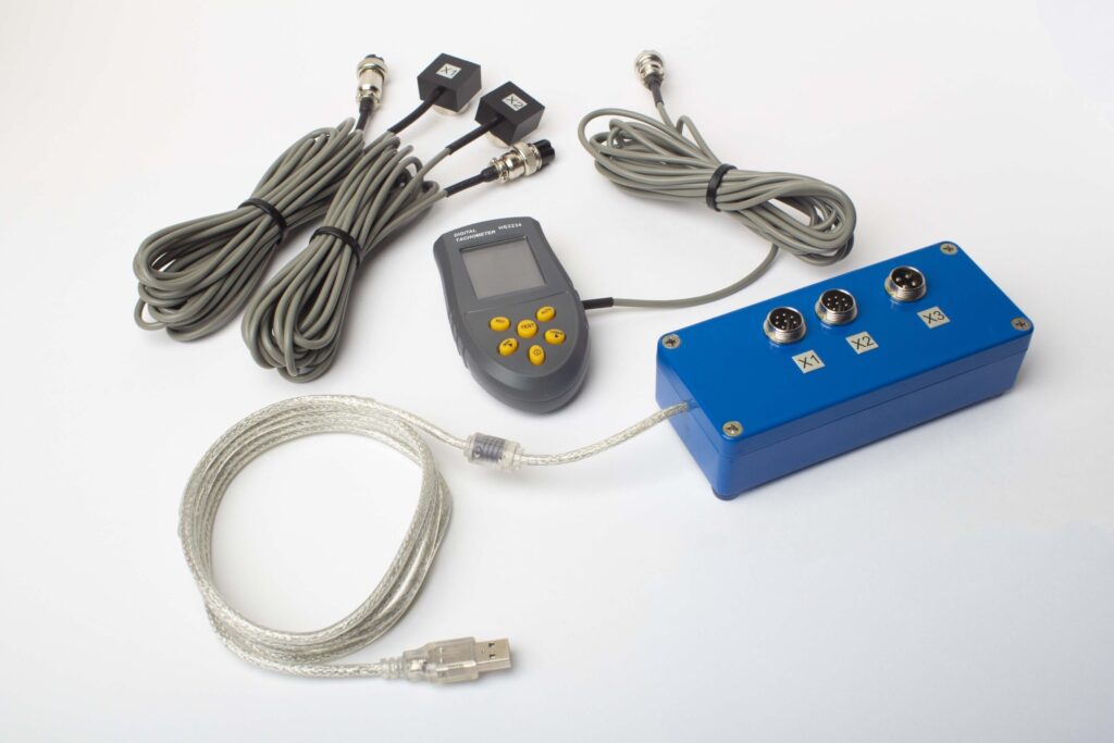
ਪੂਰੇ ਕਿੱਟ ਵਿੱਚ ਕੀ ਸ਼ਾਮਲ ਹੈ
€1,975 · ਪੂਰਾ ਕਿੱਟ, ਸਟਾਕ ਵਿੱਚ, VAT ਇਨਵੌਇਸ
- ਇੰਟਰਫੇਸ ਮਾਪ ਇਕਾਈ (USB, 2 ਚੈਨਲ)
- ਦੋ ਵਾਈਬ੍ਰੇਸ਼ਨ ਐਕਸੇਲੇਰੋਮੀਟਰ (4 m ਕੇਬਲ, 10 m ਵਿਕਲਪਿਕ)
- ਲੇਜ਼ਰ ਟੈਕੋਮੀਟਰ / ਆਪਟੀਕਲ ਫੇਜ਼ ਸੈਂਸਰ (50–500 mm)
- ਸੈਂਸਰ ਲਈ ਮੈਗਨੈਟਿਕ ਸਟੈਂਡ
- ਟਰਾਇਲ & ਸੁਧਾਰ ਵਜ਼ਨ ਲਈ ਡਿਜੀਟਲ ਸਕੇਲ
- Windows ਬੈਲੇਂਸਿੰਗ & ਵਿਸ਼ਲੇਸ਼ਣ ਸੌਫ਼ਟਵੇਅਰ
- ਪਲਾਸਟਿਕ ਟਰਾਂਸਪੋਰਟ ਕੇਸ
ਪੂਰੀ ਕਿੱਟ
ਇਕਾਈ · 2 ਸੈਂਸਰ · ਲੇਜ਼ਰ ਟੈਕੋਮੀਟਰ · ਮੈਗਨੈਟਿਕ ਸਟੈਂਡ · ਡਿਜੀਟਲ ਸਕੇਲ · ਸੌਫ਼ਟਵੇਅਰ · ਟਰਾਂਸਪੋਰਟ ਕੇਸ। ਬਾਕਸ ਤੋਂ ਬਾਹਰ ਬੈਲੇਂਸਿੰਗ ਸ਼ੁਰੂ ਕਰਨ ਲਈ ਸਭ ਕੁਝ ਲੋੜੀਂਦਾ।
OEM ਸੈੱਟ
ਇਕਾਈ · 2 ਸੈਂਸਰ · ਲੇਜ਼ਰ ਟੈਕੋਮੀਟਰ · ਸੌਫ਼ਟਵੇਅਰ। ਉਹਨਾਂ ਇੰਟੀਗ੍ਰੇਟਰਾਂ ਲਈ ਜਿਨ੍ਹਾਂ ਕੋਲ ਪਹਿਲਾਂ ਤੋਂ ਸਟੈਂਡ, ਸਕੇਲ ਅਤੇ ਕੇਸ ਹੈ, ਜਾਂ ਜੋ ਇਕਾਈ ਨੂੰ ਬੈਲੇਂਸਿੰਗ ਮਸ਼ੀਨ ਵਿੱਚ ਏਮਬੈੱਡ ਕਰਦੇ ਹਨ।
| ਪੈਰਾਮੀਟਰ | ਮੁੱਲ |
|---|---|
| ਮਾਪ ਚੈਨਲ | 2 (ਸਿੰਗਲ- & ਟੂ-ਪਲੇਨ ਬੈਲੇਂਸਿੰਗ) |
| ਵਾਈਬ੍ਰੇਸ਼ਨ ਵੇਲੋਸਿਟੀ ਰੇਂਜ | 0.2–80 mm/s RMS |
| ਫ੍ਰੀਕੁਐਂਸੀ ਰੇਂਜ | 5–1000 Hz (≤10% ਐਪਲੀਟਿਊਡ ਗਲਤੀ 550 Hz ਤੋਂ ਉੱਪਰ) |
| ਮਾਪ ਸ਼ੁੱਧਤਾ | ±5% ਪੂਰੇ ਸਕੇਲ ਦਾ |
| ਵਿਧੀ | 3-ਰਨ ਇਨਫਲੂਐਂਸ-ਕੋਏਫੀਸ਼ੀਐਂਟ (1 ਜਾਂ 2 ਸੁਧਾਰ-ਪਲੇਨ) |
| ਵਿਸ਼ਲੇਸ਼ਣ | 1× 'ਤੇ ਐਂਪਲੀਟਿਊਡ & ਫੇਜ਼, FFT ਸਪੈਕਟ੍ਰਮ & ਵੇਵਫਾਰਮ, ਸੁਰੱਖਿਅਤ ਰਿਪੋਰਟਾਂ |
| ਲੈਪਟਾਪ | ਸ਼ਾਮਲ ਨਹੀਂ (Windows PC, ਬੇਨਤੀ 'ਤੇ ਉਪਲਬਧ) |
ਅਸਲ ਵਾਈਬ੍ਰੇਸ਼ਨ-ਘਟਾਓ ਦੇ ਕੇਸ
ਜਦੋਂ ਬੈਲੈਂਸਿੰਗ ਨਾਲ ਮਦਦ ਨਹੀਂ ਮਿਲਦੀ
ਇੱਕ ਮਸ਼ੀਨ ਦੀ ਯੋਜਨਾਬੱਧ ਜਾਂਚ ਜਿੱਥੇ ਬੈਲੈਂਸ ਸੁਧਾਰਾਂ ਨਾਲ ਵਾਈਬ੍ਰੇਸ਼ਨ ਘਟਾਉਣ ਵਿੱਚ ਅਸਫਲਤਾ ਰਹੀ — ਅਤੇ ਅਸਲ ਕਾਰਨ ਕੀ ਨਿਕਲਿਆ।
ਕਿੰਨੀ ਵਾਰ ਜਾਂਚ ਕਰਨੀ ਹੈ
ਵੱਖ-ਵੱਖ ਮਸ਼ੀਨ ਕਿਸਮਾਂ ਅਤੇ ਓਪਰੇਟਿੰਗ ਵਾਤਾਵਰਣਾਂ ਲਈ ਸਿਫ਼ਾਰਸ਼ ਕੀਤੇ ਵਾਈਬ੍ਰੇਸ਼ਨ ਮਾਨੀਟਰਿੰਗ ਅੰਤਰਾਲ।
ਫੀਲਡ ਬੈਲੇਂਸਿੰਗ ਗਾਈਡ
Balanset-1A ਯੰਤਰ ਨਾਲ ਫੀਲਡ ਰੋਟਰ ਬੈਲੈਂਸਿੰਗ ਲਈ ਥਿਊਰੀ, ਅਭਿਆਸ ਅਤੇ ਸਮੱਸਿਆ-ਹੱਲ।
ਮੁਫ਼ਤ ਵਾਈਬ੍ਰੇਸ਼ਨ & ਬੈਲੈਂਸਿੰਗ ਕੈਲਕੁਲੇਟਰ
ਵਾਈਬ੍ਰੇਸ਼ਨ ਘਟਾਉਣ ਬਾਰੇ ਅਕਸਰ ਪੁੱਛੇ ਜਾਂਦੇ ਸਵਾਲ
ਮੈਂ ਰੋਟਰ ਨੂੰ ਬੈਲੈਂਸ ਕੀਤਾ ਪਰ ਮਸ਼ੀਨ ਹਾਲੇ ਵੀ ਵਾਈਬ੍ਰੇਟ ਕਰ ਰਹੀ ਹੈ — ਕਿਉਂ?
ਮੈਨੂੰ ਕਿਵੇਂ ਪਤਾ ਲੱਗੇਗਾ ਕਿ ਸਮੱਸਿਆ ਅਨਬੈਲੈਂਸ ਹੈ ਜਾਂ ਮਿਸਅਲਾਈਨਮੈਂਟ?
ਕੀ ਮੈਂ ਅਜਿਹੀ ਮਸ਼ੀਨ ਬੈਲੈਂਸ ਕਰ ਸਕਦਾ ਹਾਂ ਜਿਸ ਵਿੱਚ ਬੇਅਰਿੰਗ ਨੁਕਸਾਨ ਵੀ ਹੋਵੇ?
ISO 20816 ਦੇ ਅਨੁਸਾਰ ਕਿਹੜਾ ਵਾਈਬ੍ਰੇਸ਼ਨ ਪੱਧਰ ਸਵੀਕਾਰਯੋਗ ਹੈ?
ਘੁੰਮਣ ਵਾਲੇ ਉਪਕਰਣਾਂ ਦੀ ਵਾਈਬ੍ਰੇਸ਼ਨ ਦੀ ਜਾਂਚ ਅਤੇ ਬੈਲੈਂਸ ਕਿੰਨੀ ਵਾਰ ਕਰਨਾ ਚਾਹੀਦਾ ਹੈ?
ਜੇ ਬੈਲੈਂਸਿੰਗ ਤੋਂ ਬਾਅਦ ਜਲਦੀ ਹੀ ਵਾਈਬ੍ਰੇਸ਼ਨ ਵਾਪਸ ਆ ਜਾਵੇ ਤਾਂ ਕੀ?
ਨੁਕਸ ਦੀ ਜਾਂਚ ਕਰੋ — ਫਿਰ ਇਸਨੂੰ ਖ਼ਤਮ ਕਰੋ
Balanset-1A ਵਾਈਬ੍ਰੇਸ਼ਨ ਐਂਪਲੀਟਿਊਡ, ਫੇਜ਼ ਅਤੇ ਪੂਰਾ FFT ਸਪੈਕਟ੍ਰਮ ਮਾਪਦਾ ਹੈ ਤਾਂ ਜੋ ਤੁਸੀਂ ਸੁਧਾਰ ਕਰਨ ਤੋਂ ਪਹਿਲਾਂ ਮੂਲ ਕਾਰਨ ਦੀ ਪੁਸ਼ਟੀ ਕਰ ਸਕੋ, ਫਿਰ ਇਹ ਕਿਸੇ ਵੀ ਰਿਜਿਡ ਰੋਟਰ ਨੂੰ ਇਸ ਦੇ ਆਪਣੇ ਬੇਅਰਿੰਗਾਂ ਵਿੱਚ ਓਪਰੇਟਿੰਗ ਸਪੀਡ 'ਤੇ ਬੈਲੈਂਸ ਕਰਦਾ ਹੈ ਅਤੇ ISO 20816 ਅਤੇ ISO 21940-11 ਦੇ ਅਨੁਸਾਰ ਨਤੀਜੇ ਨੂੰ ਦਸਤਾਵੇਜ਼ੀ ਬਣਾਉਂਦਾ ਹੈ।
