ڈرائیو شافٹ بیلنسنگ: جامع گائیڈ
ڈرائیو شافٹ کے متحرک توازن کے لیے آلات اور بیلنسنگ مشینوں کے لیے پیمائش کا نظام Balanset-4 - €6,803
تصور کریں کہ آپ ٹرک چلا رہے ہیں اور گیئرز کو تیز کرتے یا تبدیل کرتے وقت اچانک ایک سخت کمپن محسوس کرتے ہیں یا ایک اونچی آواز سنائی دیتی ہے۔ یہ صرف ایک پریشانی سے زیادہ ہے - یہ غیر متوازن ڈرائیو شافٹ کی علامت ہوسکتی ہے۔ انجینئرز اور تکنیکی ماہرین کے لیے، اس طرح کے کمپن اور شور سے گمشدہ کارکردگی، اجزاء پر تیزی سے پہننے، اور اگر ایڈریس کیے بغیر چھوڑ دیا جائے تو ممکنہ طور پر مہنگا وقت کی نشاندہی کرتے ہیں۔
اس جامع گائیڈ میں، ہم ڈرائیو شافٹ بیلنس کے مسائل کے لیے عملی حل فراہم کرتے ہیں۔ آپ سیکھیں گے کہ ڈرائیو شافٹ کیا ہے اور اسے توازن کی ضرورت کیوں ہے، عام خرابیوں کو پہچانیں جو وائبریشن یا شور کا باعث بنتے ہیں، اور ڈائنامک ڈرائیو شافٹ بیلنسنگ کے لیے ایک واضح مرحلہ وار عمل کی پیروی کریں۔ ان بہترین طریقوں کو لاگو کر کے، آپ مرمت پر پیسے بچا سکتے ہیں، ٹربل شوٹنگ کے وقت کو کم کر سکتے ہیں، اور یقینی بنا سکتے ہیں کہ آپ کی مشینری یا گاڑی کم سے کم وائبریشن کے ساتھ قابل اعتماد طریقے سے چلتی ہے۔
Table of Contents
- 1. Types of Driveshafts
- 2. Universal Joint Drive Malfunctions
- 3. Driveshaft Balancing
- 4. Modern Balancing Machines for Driveshafts
- 5. Preparation for Driveshaft Balancing
- 6. Driveshaft Balancing Procedure
- 7. Recommended Balancing Accuracy Classes for Rigid Rotors


1. Types of Driveshafts
A universal joint drive (driveshaft) is a mechanism that transmits torque between shafts that intersect at the center of the universal joint and can move relative to each other at an angle. In a vehicle, the driveshaft transmits torque from the gearbox (or transfer case) to the driven axles in the case of a classical or all-wheel-drive configuration. For all-wheel-drive vehicles, the universal joint usually connects the driven shaft of the gearbox to the drive shaft of the transfer case, and the driven shafts of the transfer case to the drive shafts of the main drives of the driven axles.
فریم پر نصب یونٹس (جیسے گیئر باکس اور ٹرانسفر کیس) اپنے سپورٹ اور فریم ہی کی خرابی کی وجہ سے ایک دوسرے کے مقابلے میں حرکت کر سکتے ہیں۔ دریں اثنا، ڈرائیو ایکسل سسپنشن کے ذریعے فریم کے ساتھ منسلک ہوتے ہیں اور سسپنشن کے لچکدار عناصر کی خرابی کی وجہ سے فریم اور اس پر نصب یونٹس کی نسبت حرکت کر سکتے ہیں۔ یہ حرکت نہ صرف یونٹوں کو جوڑنے والے ڈرائیو شافٹ کے زاویوں کو بلکہ یونٹوں کے درمیان فاصلے کو بھی بدل سکتی ہے۔
The universal joint drive has a significant disadvantage: the non-uniform rotation of the shafts. If one shaft rotates uniformly, the other does not, and this non-uniformity increases with the angle between the shafts. This limitation prevents the use of a universal joint drive in many applications, such as in the transmission of front-wheel-drive vehicles, where the main issue is transmitting torque to the turning wheels. This disadvantage can be partially compensated by using double universal joints on one shaft, which are turned a quarter of a turn relative to each other. However, in applications requiring uniform rotation, constant velocity joints (CV joints) are typically used instead. CV joints are a more advanced but also more complex design serving the same purpose.
Universal joint drives can consist of one or more universal joints connected by driveshafts and intermediate supports.
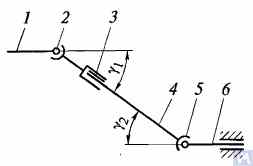
Figure 1. Diagram of a universal joint drive: 1, 4, 6 — driveshafts; 2, 5 — universal joints; 3 — compensating connection; u1, u2 — angles between shafts
عام طور پر، ایک یونیورسل جوائنٹ ڈرائیو یونیورسل جوائنٹ 2 اور 5، ڈرائیو شافٹ 1، 4، اور 6، اور ایک معاوضہ کنکشن 3 پر مشتمل ہوتی ہے۔ بعض اوقات ڈرائیو شافٹ گاڑی کے فریم کراس ممبر سے منسلک انٹرمیڈیٹ سپورٹ پر انسٹال ہوتا ہے۔ یونیورسل جوڑ ان شافٹوں کے درمیان ٹارک کی ترسیل کو یقینی بناتے ہیں جن کے محور ایک زاویہ پر آپس میں ملتے ہیں۔ یونیورسل جوڑوں کو غیر یکساں اور مستقل رفتار کی اقسام میں تقسیم کیا گیا ہے۔ غیر یکساں رفتار کے جوڑوں کو مزید لچکدار اور سخت اقسام میں درجہ بندی کیا گیا ہے۔ مستقل رفتار کے جوڑ تقسیم کرنے والے نالیوں کے ساتھ گیند کی قسم، تقسیم کرنے والے لیور کے ساتھ بال کی قسم، اور کیم کی قسم کے ہو سکتے ہیں۔ وہ عام طور پر معروف کنٹرول شدہ پہیوں کی ڈرائیو میں نصب ہوتے ہیں، جہاں شافٹ کے درمیان زاویہ 45° تک پہنچ سکتا ہے، اور یونیورسل جوائنٹ کا مرکز وہیل کے گھومنے والے محوروں اور اس کے موڑنے والے محور کے انٹرسیکشن پوائنٹ کے ساتھ موافق ہونا چاہیے۔
لچکدار عالمگیر جوڑ جڑنے والے عناصر کی لچکدار خرابی کی وجہ سے 2...3° کے زاویہ پر ایک دوسرے کو کاٹتے ہوئے محور کے ساتھ شافٹ کے درمیان ٹارک منتقل کرتے ہیں۔ ایک سخت غیر یکساں رفتار جوائنٹ سخت حصوں کے متحرک کنکشن کے ذریعے ٹارک کو ایک شافٹ سے دوسرے میں منتقل کرتا ہے۔ یہ دو جوئے پر مشتمل ہوتا ہے - 3 اور 5، بیلناکار سوراخوں میں جن کے سرے A, B, V, اور G جوڑنے والے عنصر کے - کراس 4، بیرنگ پر نصب ہوتے ہیں۔ جوئے سختی سے شافٹ 1 اور 2 سے جڑے ہوئے ہیں۔ یوک 5 کراس کے محور BG کے گرد گھوم سکتا ہے اور ایک ہی وقت میں، کراس کے ساتھ ساتھ، محور AV کے گرد بھی گھوم سکتا ہے، اس طرح ان کے درمیان بدلتے ہوئے زاویے کے ساتھ گردش کو ایک شافٹ سے دوسرے میں منتقل کرنے کے قابل بناتا ہے۔
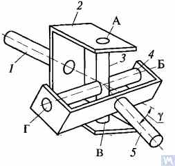
Figure 2. Diagram of a rigid non-uniform velocity universal joint
If shaft 7 rotates around its axis by an angle α, then shaft 2 will rotate by an angle β over the same period. The relationship between the rotation angles of shafts 7 and 2 is determined by the expression tanα = tanβ * cosγ، جہاں γ وہ زاویہ ہے جس پر شافٹ کے محور رکھے جاتے ہیں۔ یہ اظہار اشارہ کرتا ہے کہ زاویہ β بعض اوقات زاویہ α سے کم، برابر یا زیادہ ہوتا ہے۔ ان زاویوں کی مساوات شافٹ 7 کی گردش کے ہر 90° پر واقع ہوتی ہے۔ اس لیے، شافٹ 1 کی یکساں گردش کے ساتھ، شافٹ 2 کی کونیی رفتار غیر یکساں ہے اور سائنوسائیڈل قانون کے مطابق مختلف ہوتی ہے۔ شافٹ 2 کی گردش کی عدم یکسانیت شافٹ کے محوروں کے درمیان زاویہ γ بڑھنے سے زیادہ اہم ہو جاتی ہے۔
If the non-uniform rotation of shaft 2 is transmitted to the shafts of the units, additional pulsating loads will occur in the transmission, increasing with the angle γ. To prevent the non-uniform rotation of shaft 2 from being transmitted to the unit shafts, two universal joints are used in the universal joint drive. They are installed so that the angles γ1 and γ2 are equal; the forks of the universal joints, fixed on the non-uniformly rotating shaft 4, should be positioned in the same plane.
یونیورسل جوائنٹ ڈرائیوز کے اہم حصوں کا ڈیزائن شکل 3 میں دکھایا گیا ہے۔ ایک غیر یکساں رفتار عالمگیر جوائنٹ دو جوئے پر مشتمل ہوتا ہے (1) ایک کراس (3) سے جڑا ہوتا ہے۔ جوئے میں سے ایک میں بعض اوقات ایک فلینج ہوتا ہے، جب کہ دوسرے کو ڈرائیو شافٹ ٹیوب میں ویلڈ کیا جاتا ہے یا ڈرائیو شافٹ سے کنکشن کے لیے اس کا سرہ (6) (یا آستین) ہوتا ہے۔ سوئی کے بیرنگ (7) پر دونوں جوئے کی آنکھوں میں صلیب کے ٹرونین نصب ہیں۔ ہر بیئرنگ کو ایک کیس (2) میں رکھا جاتا ہے اور جوئے کی آنکھ میں ایک ٹوپی کے ساتھ پکڑا جاتا ہے، جو واشر پر ٹیبز کے ذریعے بند دو بولٹ کے ساتھ جوئے کے ساتھ جڑا ہوتا ہے۔ کچھ صورتوں میں، بیرنگ کو اسنیپ رِنگز کے ساتھ جوئے میں محفوظ کیا جاتا ہے۔ بیئرنگ میں پھسلن کو برقرار رکھنے اور اسے پانی اور گندگی سے بچانے کے لیے، ربڑ کی خود کو سخت کرنے والی مہر ہے۔ کراس کی اندرونی گہا گریس فٹنگ کے ذریعے چکنائی سے بھری ہوئی ہے، جو بیرنگ تک پہنچتی ہے۔ کراس میں عام طور پر ایک حفاظتی والو ہوتا ہے جو کراس میں ڈالی جانے والی چکنائی کے دباؤ کی وجہ سے مہر کو نقصان سے بچاتا ہے۔ کٹے ہوئے کنکشن (6) کو چکنائی کی فٹنگ (5) کا استعمال کرتے ہوئے چکنا کیا جاتا ہے۔
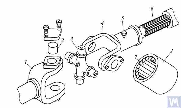
Figure 3. Details of a rigid non-uniform velocity universal joint
سخت غیر یکساں رفتار عالمگیر جوڑوں کے ذریعے جڑے ہوئے شافٹ کے محوروں کے درمیان زیادہ سے زیادہ زاویہ عام طور پر 20° سے زیادہ نہیں ہوتا، کیونکہ بڑے زاویوں پر کارکردگی نمایاں طور پر کم ہو جاتی ہے۔ اگر شافٹ کے محوروں کے درمیان زاویہ 0...2% کے اندر مختلف ہوتا ہے، تو کراس کے ٹرونین سوئی کے بیرنگ سے بگڑ جاتے ہیں، جس کی وجہ سے عالمگیر جوڑ تیزی سے ناکام ہو جاتا ہے۔
تیز رفتار ٹریک شدہ گاڑیوں کی ترسیل میں، گیئر کپلنگ کی اقسام کے ساتھ یونیورسل جوائنٹ، جو 1.5...2° تک کے زاویوں پر ایک دوسرے کو کاٹتے ہوئے محوروں کے ساتھ شافٹ کے درمیان ٹارک کی ترسیل کی اجازت دیتے ہیں، اکثر استعمال ہوتے ہیں۔
Driveshafts are typically made tubular, using special steel seamless or welded tubes. The yokes of the universal joints, splined sleeves, or tips are welded to the tubes. To reduce the transverse loads acting on the driveshaft, dynamic balancing is performed with the universal joints assembled. Imbalance is corrected by welding balancing plates to the driveshaft or sometimes by installing balancing plates under the bearing caps of the universal joints. The relative position of the splined connection parts after assembly and balancing of the universal joint drive at the factory is usually marked with special labels.
The compensating connection of the universal joint drive is usually made in the form of a splined connection, allowing axial movement of the universal joint drive parts. It consists of a splined tip that fits into the splined sleeve of the universal joint drive. Lubrication is introduced into the splined connection through a grease fitting or applied during assembly and replaced after prolonged use of the vehicle. A seal and a cover are typically installed to prevent grease leakage and contamination.
For long driveshafts, intermediate supports are usually used in universal joint drives. An intermediate support typically consists of a bracket bolted to the vehicle frame cross member, in which a ball bearing is mounted in a rubber elastic ring. The bearing is sealed on both sides with caps and has a lubrication device. The elastic rubber ring helps to compensate for assembly inaccuracies and bearing misalignment that may occur due to frame deformations.
A universal joint with needle bearings (Figure 4a) consists of yokes, a cross, needle bearings, and seals. The cups with needle bearings are fitted onto the trunnions of the cross and sealed with seals. The cups are secured in the yokes with snap rings or caps fastened with screws. Universal joints are lubricated through a grease fitting via internal drillings in the cross. A safety valve is used to eliminate excess oil pressure in the joint. During uniform rotation of the driving yoke, the driven yoke rotates non-uniformly: it advances and lags behind the driving yoke twice per revolution. To eliminate non-uniform rotation and reduce inertial loads, two universal joints are used.
In the drive to the front driving wheels, constant velocity universal joints are installed. The constant velocity joint drive of GAZ-66 and ZIL-131 vehicles consists of yokes 2, 5 (Figure 4b), four balls 7, and a central ball 8. The driving yoke 2 is integral with the inner axle shaft, while the driven yoke is forged together with the outer axle shaft, at the end of which the wheel hub is fixed. The driving moment from yoke 2 to yoke 5 is transmitted through balls 7, which move along circular grooves in the yokes. The central ball 8 serves to center the yokes and is held in place by studs 3, 4. The rotation frequency of yokes 2, 5 is the same due to the symmetry of the mechanism relative to the yokes. The change in shaft length is ensured by the free splined connections of the yokes with the shaft.
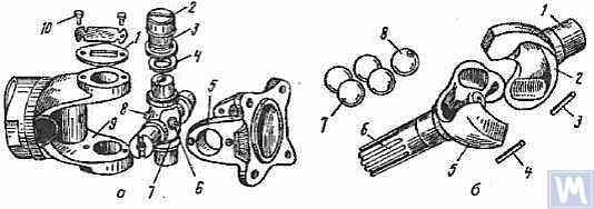
Figure 4. Universal Joints: a — universal joint: 1 — cap; 2 — cup; 3 — needle bearing; 4 — seal; 5, 9 — yokes; 6 — safety valve; 7 — cross; 8 — grease fitting; 10 — screw; b — constant velocity universal joint: 1 — inner axle shaft; 2 — driving yoke; 3, 4 — studs; 5 — driven yoke; 6 — outer axle shaft; 7 — balls; 8 — central ball
2. Universal Joint Drive Malfunctions
Universal joint drive malfunctions typically manifest as sharp knocks in the universal joints that occur when the vehicle is moving, especially during shifts between gears and sudden increases in the engine crankshaft speed (for example, when transitioning from engine braking to acceleration). A sign of universal joint malfunction can be its heating to a high temperature (over 100°C). This happens due to significant wear of the bushings and trunnions of the universal joint, needle bearings, crosses, and splined connections, resulting in misalignment of the universal joint and significant impact axial loads on the needle bearings. Damage to the cork seals of the universal joint cross leads to rapid wear of the trunnion and its bearing.
During maintenance, the universal joint drive is checked by sharply rotating the driveshaft by hand in both directions. The degree of free rotation of the shaft determines the wear of the universal joints and splined connections. Every 8-10 thousand kilometers, the condition of the bolted connections of the driven shaft flanges of the gearbox and the drive shaft of the main transmission gear with the flanges of the end universal joints and the fastening of the intermediate support of the driveshaft are checked. The condition of the rubber boots on the splined connections and the cork seals of the universal joint cross is also checked. All fastening bolts must be tightened fully (tightening torque 8-10 kgf·m).
Needle bearings of the universal joints are lubricated with liquid oil used for transmission units; splined connections in most vehicles are lubricated with greases (US-1, US-2, 1-13, etc.); the use of grease for lubricating needle bearings is strictly prohibited. In some vehicles, splined connections are lubricated with transmission oil. The intermediate support bearing, mounted in a rubber sleeve, practically does not require lubrication, as it is lubricated during assembly at the factory. The support bearing of the ZIL-130 vehicle is lubricated with grease through a pressure fitting during regular maintenance (every 1100-1700 km).
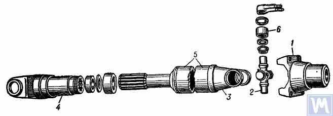
Figure 5. Universal joint drive: 1 — flange for securing the driveshaft; 2 — universal joint cross; 3 — universal joint yoke; 4 — sliding yoke; 5 — driveshaft tube; 6 — needle roller bearing with closed end
The universal joint drive consists of two universal joints with needle bearings, connected by a hollow shaft, and a sliding yoke with involute splines. To ensure reliable protection from dirt and provide good lubrication of the splined connection, the sliding yoke (6), connected to the secondary shaft (2) of the gearbox, is placed in an extension (1) attached to the gearbox housing. Additionally, this location of the splined connection (outside the zone between the joints) significantly increases the stiffness of the universal joint drive and reduces the likelihood of shaft vibrations when the sliding splined connection wears out.
ڈرائیو شافٹ ایک پتلی دیواروں والی الیکٹرک ویلڈیڈ ٹیوب (8) سے بنی ہوتی ہے، جس میں دو ایک جیسے جوئے (9) ہر سرے پر پریس لگائے جاتے ہیں اور پھر آرک ویلڈنگ کے ذریعے ویلڈنگ کی جاتی ہے۔ کراس (25) کے سوئی بیئرنگ ہاؤسنگز (18) جوئے کی آنکھوں میں دبائے گئے ہیں (9) اور بہار برقرار رکھنے والی انگوٹھیوں (20) سے محفوظ ہیں۔ ہر یونیورسل جوائنٹ بیئرنگ میں 22 سوئیاں (21) ہوتی ہیں۔ اسٹیمپڈ ٹوپیاں (24) صلیب کے پھیلے ہوئے ٹرونینز پر پریس سے لگائی جاتی ہیں، جس میں کارک کے حلقے (23) نصب ہوتے ہیں۔ بیرنگوں کو کراس کے بیچ میں ایک دھاگے والے سوراخ میں ایک اینگولر گریس فٹنگ (17) کا استعمال کرتے ہوئے چکنا کیا جاتا ہے، جو کراس کے ٹرونینز میں چینلز کے ذریعے منسلک ہوتا ہے۔ یونیورسل جوائنٹ کراس کے مخالف سمت میں، ایک حفاظتی والو (16) اس کے مرکز میں واقع ہے، جو کراس اور بیرنگ کو بھرتے وقت اضافی چکنائی چھوڑنے کے لیے، اور آپریشن کے دوران کراس کے اندر دباؤ بڑھنے سے روکنے کے لیے ڈیزائن کیا گیا ہے (والو تقریباً 3.5 کلوگرام/سینٹی میٹر کے دباؤ پر فعال ہوتا ہے)۔ حفاظتی والو کو شامل کرنے کی ضرورت اس حقیقت کی وجہ سے ہے کہ کراس کے اندر بہت زیادہ دباؤ بڑھنے سے کارک سیل کو نقصان پہنچ سکتا ہے۔
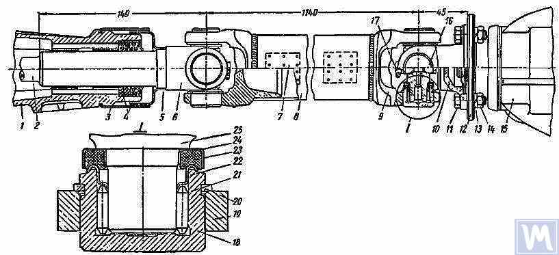
Figure 6. Driveshaft Assembly: 1 — gearbox extension; 2 — secondary shaft of the gearbox; 3 and 5 — dirt deflectors; 4 — rubber seals; 6 — sliding yoke; 7 — balancing plate; 8 — driveshaft tube; 9 — yoke; 10 — flange yoke; 11 — bolt; 12 — flange of the rear axle drive gear; 13 — spring washer; 14 — nut; 15 — rear axle; 16 — safety valve; 17 — angular grease fitting; 18 — needle bearing; 19 — yoke eye; 20 — spring retaining ring; 21 — needle; 22 — washer with toroidal end; 23 — cork ring; 24 — stamped cap; 25 — cross
ڈرائیو شافٹ، جو دونوں عالمگیر جوڑوں کے ساتھ جمع ہوتا ہے، ٹیوب میں بیلنسنگ پلیٹس (7) کو ویلڈنگ کرکے دونوں سروں پر احتیاط سے متحرک طور پر متوازن ہوتا ہے۔ لہذا، شافٹ کو جدا کرتے وقت، اس کے تمام حصوں کو احتیاط سے نشان زد کیا جانا چاہئے تاکہ وہ ان کی اصل پوزیشنوں میں دوبارہ جمع ہوسکیں. اس ہدایت پر عمل کرنے میں ناکامی شافٹ کے توازن میں خلل ڈالتی ہے، جس سے کمپن ہوتی ہے جو ٹرانسمیشن اور گاڑی کے جسم کو نقصان پہنچا سکتی ہے۔ اگر انفرادی حصے ختم ہو جائیں، خاص طور پر اگر ٹیوب اثر کی وجہ سے جھک جائے اور اسمبلی کے بعد شافٹ کو متحرک طور پر متوازن کرنا ناممکن ہو جائے، تو پورے شافٹ کو تبدیل کرنا ضروری ہے۔
Possible Driveshaft Malfunctions, Their Causes, and Solutions
| Cause of Malfunction | Solution |
|---|---|
| Driveshaft Vibration | |
| 1. Shaft bending due to an obstacle | 1. Straighten and dynamically balance the assembled shaft or replace the assembled shaft |
| 2. Bearing and cross wear | 2. Replace bearings and crosses and dynamically balance the assembled shaft |
| 3. Wear of extension bushings and sliding yoke | 3. Replace the extension and sliding yoke and dynamically balance the assembled shaft |
| Knocks When Starting and Coasting | |
| 1. Wear of sliding yoke splines or secondary gearbox shaft | 1. Replace worn parts. When replacing the sliding yoke, dynamically balance the assembled shaft |
| 2. Loose bolts securing the flange yoke to the rear axle drive gear flange | 2. Tighten bolts |
| Oil Throwing from Universal Joint Seals | |
| Wear of cork rings in universal joint seals | Replace cork rings, maintaining the relative position of all driveshaft parts during reassembly. If there is wear on crosses and bearings, replace the bearings and crosses and dynamically balance the assembled shaft |
3. Driveshaft Balancing
After repairing and assembling the driveshaft, it is dynamically balanced on a machine. One design of a balancing machine is shown in Figure 7. The machine consists of a plate (18), a pendulum frame (8) mounted on four vertical elastic rods (3), ensuring its oscillation in the horizontal plane. A bracket and front headstock (9), secured on a bracket (4), are mounted on the longitudinal tubes of the pendulum frame (8). The rear headstock (6) is on a movable traverse (5), allowing dynamic balancing of driveshafts of different lengths. The headstock spindles are mounted on precision ball bearings. The spindle of the front headstock (9) is driven by an electric motor installed in the machine base, through a V-belt drive and an intermediate shaft, on which a limb (10) (graduated disk) is mounted. Additionally, two stands (15) with retractable locking pins (17) are installed on the machine plate (18), ensuring the fixation of the front and rear ends of the pendulum frame depending on the balancing of the front or rear end of the driveshaft.
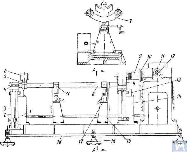
Figure 7. Dynamic Balancing Machine for Driveshafts
1—clamp; 2—dampers; 3—elastic rod; 4—bracket; 5—movable traverse; 6—rear headstock; 7—crossbar; 8—pendulum frame; 9—front driving headstock; 10—limb-disk; 11—millivoltmeter; 12—limb of the commutator-rectifier shaft; 13—magnetoelectric sensor; 14—fixed stand; 15—fixator stand; 16—support; 17—fixator; 18—support plate
The fixed stands (14) are mounted at the rear of the machine plate, and magnetoelectric sensors (13) are installed on them, with rods connected to the ends of the pendulum frame. To prevent resonance vibrations of the frame, dampers (2) filled with oil are installed under the brackets (4).
متحرک توازن کے دوران، سلائیڈنگ یوک کے ساتھ ڈرائیو شافٹ اسمبلی کو مشین پر انسٹال اور محفوظ کیا جاتا ہے۔ ڈرائیو شافٹ کا ایک سرا سامنے والے ڈرائیونگ ہیڈ اسٹاک کے فلینج کے ساتھ فلانج یوک کے ذریعے جڑا ہوا ہے، اور دوسرا سرہ سلائیڈنگ یوک کی سپورٹ گردن کے ذریعے عقبی ہیڈ اسٹاک کی کٹی ہوئی آستین سے جڑا ہوا ہے۔ پھر ڈرائیو شافٹ کی گردش کی آسانی کی جانچ پڑتال کی جاتی ہے، اور مشین کے پینڈولم فریم کے ایک سرے کو فکسیٹر کا استعمال کرتے ہوئے طے کیا جاتا ہے۔ مشین شروع کرنے کے بعد، ریکٹیفائر کے اعضاء کو گھڑی کی مخالف سمت میں گھمایا جاتا ہے، جس سے ملی وولٹ میٹر کی سوئی اس کی زیادہ سے زیادہ ریڈنگ تک پہنچ جاتی ہے۔ ملی وولٹ میٹر ریڈنگ عدم توازن کی شدت سے مساوی ہے۔ ملی وولٹ میٹر پیمانہ گرام سینٹی میٹر یا کاؤنٹر ویٹ کے گرام میں گریجویٹ کیا جاتا ہے۔ ریکٹیفائر اعضاء کو گھڑی کی مخالف سمت میں گھومنا جاری رکھتے ہوئے، ملی وولٹ میٹر ریڈنگ صفر پر لایا جاتا ہے، اور مشین کو روک دیا جاتا ہے۔ ریکٹیفائر اعضاء کی ریڈنگ کی بنیاد پر، کونیی نقل مکانی (عدم توازن کی نقل مکانی کا زاویہ) کا تعین کیا جاتا ہے، اور ڈرائیو شافٹ کو دستی طور پر گھمانے سے، یہ قدر انٹرمیڈیٹ شافٹ اعضاء پر سیٹ کی جاتی ہے۔ بیلنسنگ پلیٹ کی ویلڈنگ کی جگہ ڈرائیو شافٹ کے اوپری حصے پر ہوگی، اور اصلاحی جہاز میں وزنی حصہ نیچے ہوگا۔ پھر بیلنسنگ پلیٹ کو ویلڈ سے 10 ملی میٹر کے فاصلے پر پتلی تار سے جوڑ کر باندھ دیا جاتا ہے، مشین کو شروع کیا جاتا ہے، اور پلیٹ کے ساتھ ڈرائیو شافٹ اینڈ کا توازن چیک کیا جاتا ہے۔ عدم توازن 70 جی سینٹی میٹر سے زیادہ نہیں ہونا چاہئے۔ پھر، ایک سرے کو جاری کرتے ہوئے اور پینڈولم فریم کے دوسرے سرے کو فکسیٹر اسٹینڈ کے ساتھ محفوظ کرتے ہوئے، ڈرائیو شافٹ کے دوسرے سرے کا متحرک توازن اوپر بیان کردہ تکنیکی ترتیب کے مطابق انجام دیا جاتا ہے۔
Driveshafts have some balancing features. For most parts, the base for dynamic balancing is the support necks (e.g., rotors of electric motors, turbines, spindles, crankshafts, etc.), but for driveshafts, it is the flanges. During assembly, there are unavoidable gaps in different connections leading to imbalance. If the minimum imbalance cannot be achieved during balancing, the shaft is rejected. The accuracy of balancing is influenced by the following factors:
- Gap in the connection between the landing belt of the driveshaft flange and the inner hole of the clamping flange of the left and right support headstocks;
- Radial and end runout of the base surfaces of the flange;
- قبضہ اور منقطع کنکشن میں خلا۔ کٹے ہوئے کنکشن کی گہا میں چکنائی کی موجودگی "تیرتے" عدم توازن کا باعث بن سکتی ہے۔ اگر یہ مطلوبہ توازن کی درستگی کو حاصل کرنے سے روکتا ہے، تو ڈرائیو شافٹ بغیر چکنائی کے متوازن ہے۔
Some imbalances may be completely uncorrectable. If increased friction is observed in the universal joints of the driveshaft, the mutual influence of the correction planes increases. This leads to a decrease in the performance and accuracy of balancing.
OST 37.001.053-74 کے مطابق، مندرجہ ذیل عدم توازن کے معیارات قائم کیے گئے ہیں: دو جوڑوں (دو سپورٹ) کے ساتھ ڈرائیو شافٹ متحرک طور پر متوازن ہیں، اور تین (تھری سپورٹ) کے ساتھ - درمیانی سپورٹ کے ساتھ جمع؛ 5 کلوگرام سے زیادہ وزنی ڈرائیو شافٹ اور کپلنگز کے فلینجز (جوئے) شافٹ یا کپلنگ کو جمع کرنے سے پہلے مستحکم طور پر متوازن ہوتے ہیں۔ ہر سرے پر یا تین جوائنٹ ڈرائیو شافٹ کے درمیانی تعاون پر ڈرائیو شافٹ کے بقایا عدم توازن کے اصولوں کو مخصوص عدم توازن سے جانچا جاتا ہے۔
شافٹ کے ہر سرے پر یا انٹرمیڈیٹ سپورٹ پر، نیز بیلنسنگ اسٹینڈ پر کسی بھی پوزیشن میں تین جوائنٹ ڈرائیو شافٹ کے لیے زیادہ سے زیادہ قابل اجازت مخصوص بقایا عدم توازن کا معیار زیادہ نہیں ہونا چاہیے: مسافر کاروں اور چھوٹے بوجھ والے ٹرکوں کی ترسیل کے لیے (1 t تک) اور بہت چھوٹی بسوں کے لیے - 6 g-cm/kg/kg. باقی کے لیے ڈرائیو شافٹ یا تھری جوائنٹ ڈرائیو شافٹ کے زیادہ سے زیادہ قابل اجازت بقایا عدم توازن کے معیار کو بیلنسنگ اسٹینڈ پر گھومنے والی فریکوئنسی پر یقینی بنایا جانا چاہیے جو گاڑی کی زیادہ سے زیادہ رفتار پر ٹرانسمیشن میں ان کی فریکوئنسیوں کے مطابق ہو۔
4 t اور اس سے اوپر کی لوڈ کی گنجائش والے ٹرکوں کے ڈرائیو شافٹ اور تین جوائنٹ ڈرائیو شافٹ کے لیے، چھوٹی اور بڑی بسوں کے لیے، بیلنسنگ اسٹینڈ پر گردش کی فریکوئنسی میں زیادہ سے زیادہ گاڑی کی رفتار پر ٹرانسمیشن شافٹ کی گردش کی فریکوئنسی کی 70% تک کمی کی اجازت ہے۔ OST 37.001.053-74 کے مطابق، ڈرائیو شافٹ کی توازن گردش کی فریکوئنسی اس کے برابر ہونی چاہیے:
nb = (0.7 ... 1.0) اینr,
where nb - توازن گردش کی فریکوئنسی (اسٹینڈ کے اہم تکنیکی ڈیٹا کے مطابق ہونا چاہیے، n=3000 منٹ-1; nr - زیادہ سے زیادہ کام کرنے والی گردش کی فریکوئنسی، کم سے کم-1.
In practice, due to the gap in the joints and splined connections, the driveshaft cannot be balanced at the recommended rotation frequency. In this case, another rotation frequency is chosen, at which it balances.
4. Modern Balancing Machines for Driveshafts
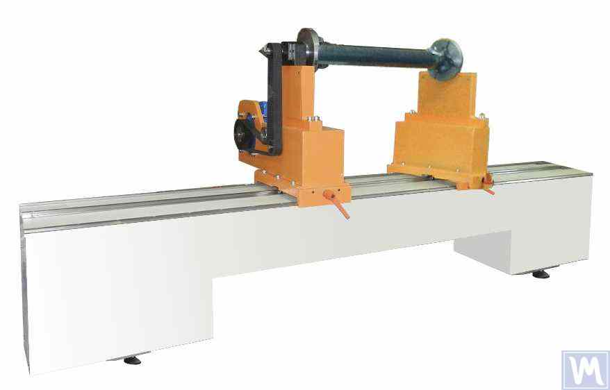
Figure 8. Balancing Machine for Driveshafts up to 2 Meters Long, Weighing up to 500 kg
The model has 2 stands and allows balancing in 2 correction planes.
Balancing Machine for Driveshafts up to 4200 mm Long, Weighing up to 400 kg
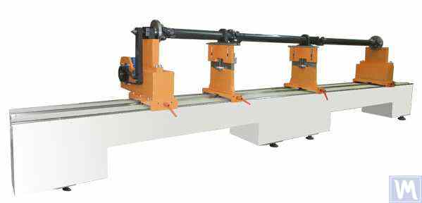
Figure 9. Balancing Machine for Driveshafts up to 4200 mm Long, Weighing up to 400 kg
The model has 4 stands and allows balancing in 4 correction planes simultaneously.
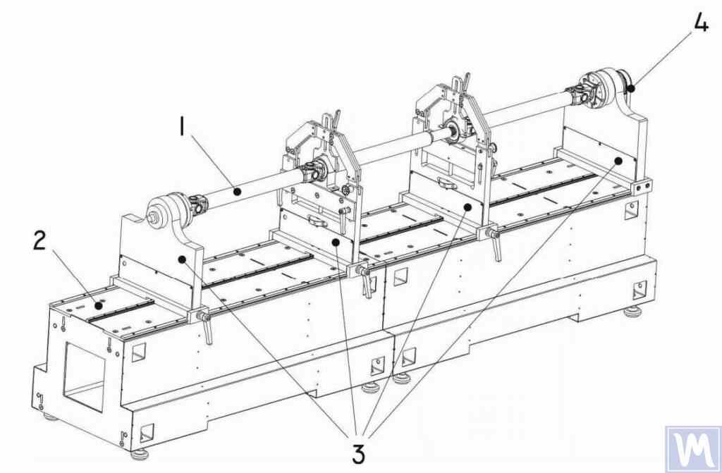
Figure 10. Horizontal Hard Bearing Balancing Machine for Dynamic Balancing of Driveshafts
1 – Balancing item (driveshaft); 2 – Machine base; 3 – Machine supports; 4 – Machine drive; The structural elements of the machine supports are shown in Figure 9.
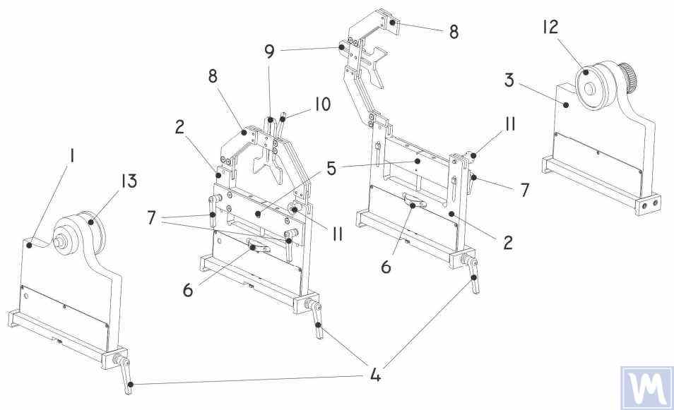
Figure 11. Machine Support Elements for Dynamic Balancing of Driveshafts
1 – Left non-adjustable support; 2 – Intermediate adjustable support (2 pcs.); 3 – Right non-adjustable fixed support; 4 – Support frame lock handle; 5 – Movable support platform; 6 – Support vertical adjustment nut; 7 – Vertical position lock handles; 8 – Support clamping bracket; 9 – Intermediate bearing movable clamp; 10 – Clamp lock handle; 11 – Clamping bracket lock; 12 – Drive (leading) spindle for item installation; 13 – Driven spindle
5. Preparation for Driveshaft Balancing
Below, we will consider the setup of the machine supports and the installation of the balancing item (four-support driveshaft) on the machine supports.
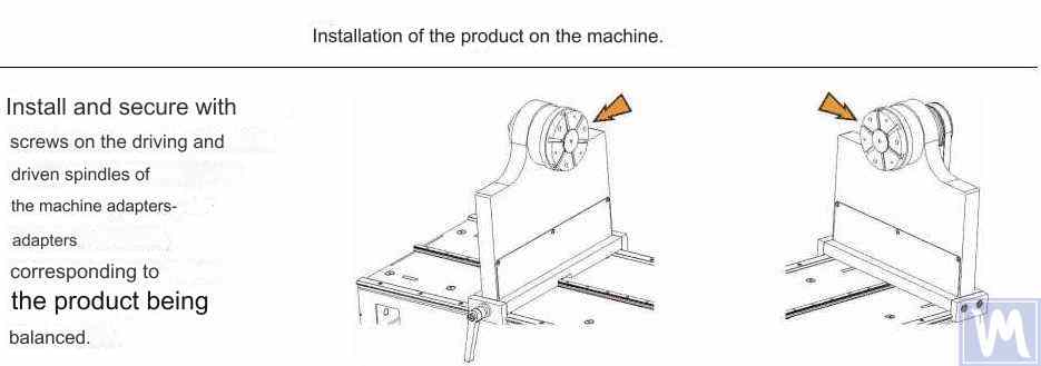
Figure 12. Installation of Transitional Flanges on the Spindles of the Balancing Machine
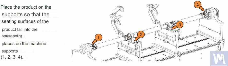
Figure 13. Installation of the Driveshaft on the Supports of the Balancing Machine
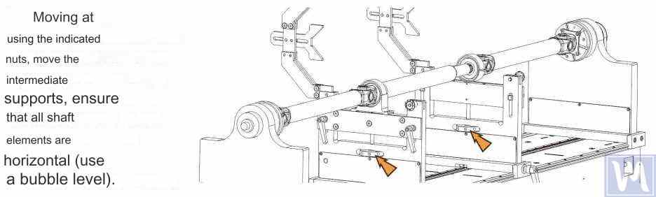
Figure 14. Leveling the Driveshaft Horizontally on the Supports of the Balancing Machine Using a Bubble Level
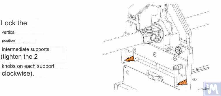
Figure 15. Fixing the Intermediate Supports of the Balancing Machine to Prevent Vertical Displacement of the Driveshaft
Rotate the item manually for a full turn. Ensure that it rotates freely and without jamming on the supports. After this, the mechanical part of the machine is set up, and the item installation is complete.
6. Driveshaft Balancing Procedure
The process of driveshaft balancing on the balancing machine will be considered using the Balanset-4 measuring system as an example. The Balanset-4 is a portable balancing kit designed for balancing in one, two, three, and four correction planes of rotors, either rotating in their own bearings or mounted on a balancing machine. The device includes up to four vibration sensors, a phase angle sensor, a four-channel measuring unit, and a portable computer.
The entire balancing process, including measurement, processing, and display of information on the magnitude and location of corrective weights, is performed automatically and does not require the user to have additional skills and knowledge beyond the provided instructions. The results of all balancing operations are saved in the Balancing Archive and can be printed as reports if necessary. In addition to balancing, the Balanset-4 can also be used as a regular vibro-tachometer, allowing measurement on four channels of the root mean square (RMS) value of total vibration, RMS of the rotational component of vibration, and control of rotor rotation frequency.
Furthermore, the device allows displaying graphs of the time function and vibration spectrum by vibration velocity, which can be useful in assessing the technical condition of the balanced machine.
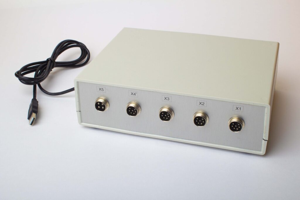
Figure 16. External View of the Balanset-4 Device for Use as a Measuring and Computing System of the Driveshaft Balancing Machine
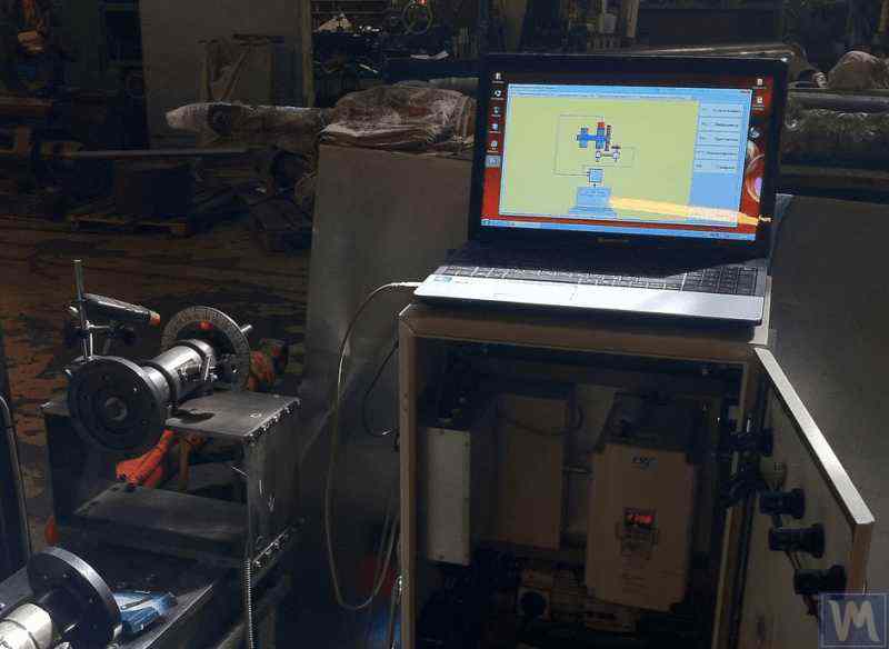
Figure 17. Example of Using the Balanset-4 Device as a Measuring and Computing System of the Driveshaft Balancing Machine
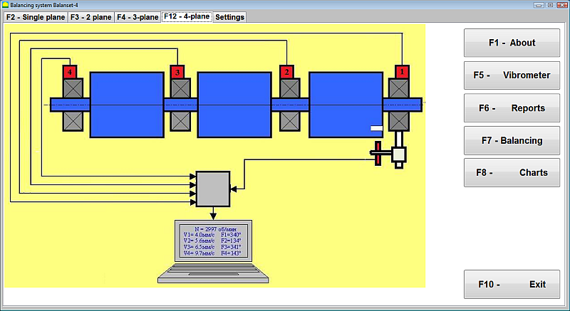
Figure 18. User Interface of the Balanset-4 Device
Balanset-4 ڈیوائس دو قسم کے سینسرز سے لیس ہو سکتی ہے - کمپن (وائبریشن ایکسلریشن) اور فورس سینسرز کی پیمائش کے لیے وائبریشن ایکسلرومیٹر۔ وائبریشن سینسرز پوسٹ ریزوننس ٹائپ بیلنسنگ مشینوں پر کام کرنے کے لیے استعمال کیے جاتے ہیں، جبکہ فورس سینسر پری ریزوننس ٹائپ مشینوں کے لیے استعمال کیے جاتے ہیں۔
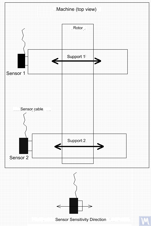
Figure 19. Installation of Balanset-4 Vibration Sensors on the Supports of the Balancing Machine
سینسرز کی حساسیت کے محور کی سمت سپورٹ کے کمپن کی نقل مکانی کی سمت سے مماثل ہونی چاہیے، اس صورت میں - افقی۔ سینسر کی تنصیب کے بارے میں اضافی معلومات کے لیے، آپریٹنگ کنڈیشنز میں بیلنسنگ روٹرز دیکھیں۔ فورس سینسر کی تنصیب مشین کے ڈیزائن کی خصوصیات پر منحصر ہے۔
- Install vibration sensors 1, 2, 3, 4 on the supports of the balancing machine.
- Connect the vibration sensors to connectors X1, X2, X3, X4.
- Install the phase angle sensor (laser tachometer) 5 so that the nominal gap between the radial (or end) surface of the balanced rotor and the sensor housing is in the range of 10 to 300 mm.
- Attach a reflective tape mark with a width of at least 10-15 mm to the rotor surface.
- Connect the phase angle sensor to connector X5.
- Connect the measuring unit to the computer’s USB port.
- When using mains power, connect the computer to the power supply unit.
- Connect the power supply unit to a 220 V, 50 Hz network.
- Turn on the computer and select the “BalCom-4” program.
- Press the “F12-four-plane” button (or the F12 function key on the computer keyboard) to select the mode for measuring vibration simultaneously in four planes using vibration sensors 1, 2, 3, 4, connected respectively to inputs X1, X2, X3, and X4 of the measuring unit.
- A mnemonic diagram illustrating the process of measuring vibration simultaneously on four measurement channels (or the process of balancing in four planes) appears on the computer display, as shown in Figure 16.
Before performing balancing, it is recommended to take measurements in the vibrometer mode (F5 button).
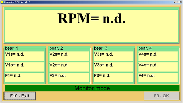
Figure 20. Vibrometer Mode Measurements
اگر کل وائبریشن کی شدت V1s (V2s) تقریباً گردشی جزو کی شدت V1o (V2o) سے مماثل ہے، تو یہ فرض کیا جا سکتا ہے کہ میکانزم کی کمپن میں بنیادی شراکت روٹر کے عدم توازن کی وجہ سے ہے۔ اگر کل وائبریشن کی شدت V1s (V2s) گردشی جزو V1o (V2o) سے نمایاں طور پر بڑھ جاتی ہے، تو یہ تجویز کی جاتی ہے کہ میکانزم کا معائنہ کریں - بیرنگ کی حالت کو چیک کریں، فاؤنڈیشن پر محفوظ نصب ہونے کو یقینی بنائیں، تصدیق کریں کہ روٹر گردش کے دوران اسٹیشنری حصوں سے رابطہ نہیں کرتا، اور دیگر vibrchanism کے اثر و رسوخ پر غور کریں۔
"Graphs-Spectral Analysis" موڈ میں حاصل کردہ ٹائم فنکشن گرافس اور وائبریشن سپیکٹرا کا مطالعہ یہاں مفید ہو سکتا ہے۔
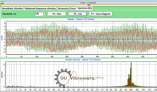
Figure 21. Vibration Time Function and Spectrum Graphs
گراف دکھاتا ہے کہ کن فریکوئنسیوں پر کمپن کی سطح سب سے زیادہ ہے۔ اگر یہ تعدد متوازن میکانزم کے روٹر کی گردشی تعدد سے مختلف ہے، تو یہ ضروری ہے کہ ان کمپن کے اجزاء کے ذرائع کی نشاندہی کی جائے اور توازن قائم کرنے سے پہلے انہیں ختم کرنے کے لیے اقدامات کیے جائیں۔
It is also important to pay attention to the stability of the readings in vibrometer mode – the amplitude and phase of the vibration should not change by more than 10-15% during measurement. Otherwise, the mechanism might be operating near a resonance region. In this case, the rotor speed should be adjusted.
"پرائمری" موڈ میں فور پلین بیلنسنگ کرتے وقت، پانچ کیلیبریشن رن اور متوازن مشین کی کم از کم ایک توثیقی رن کی ضرورت ہوتی ہے۔ آزمائشی وزن کے بغیر چلنے والی پہلی مشین کے دوران کمپن کی پیمائش "فور پلین بیلنسنگ" ورک اسپیس میں کی جاتی ہے۔ اس کے بعد کی رنز آزمائشی وزن کے ساتھ انجام دی جاتی ہیں، ترتیب وار ہر کریکشن ہوائی جہاز میں ڈرائیو شافٹ پر نصب کی جاتی ہیں (ہر بیلنسنگ مشین سپورٹ کے علاقے میں)۔
Before each subsequent run, the following steps should be taken:
- متوازن مشین کے روٹر کی گردش کو روکیں۔
- Remove the previously installed trial weight.
- Install the trial weight in the next plane.
Figure 23. Four-Plane Balancing Workspace
ہر پیمائش کو مکمل کرنے کے بعد، روٹر کی گردش کی فریکوئنسی کے نتائج (Nob), as well as the RMS values (Vo1، ویo2، ویo3، ویo4) and the phases (F1, F2, F3, F4) متوازن روٹر کی گردشی فریکوئنسی پر وائبریشن کو پروگرام ونڈو میں متعلقہ فیلڈز میں محفوظ کیا جاتا ہے۔ پانچویں رن (طیارے 4 میں وزن) کے بعد، "متوازن وزن" ورک اسپیس (تصویر 24 دیکھیں) ظاہر ہوتا ہے، جو عوام کی حسابی قدروں کو ظاہر کرتا ہے (M1, M2, M3, M4) and the installation angles (f1, f2, f3, f4) of the corrective weights that need to be installed on the rotor in four planes to compensate for its imbalance.
Figure 24. Workspace with Calculated Parameters of Corrective Weights in Four Planes
Attention! متوازن مشین کے پانچویں رن کے دوران پیمائش کے عمل کو مکمل کرنے کے بعد، روٹر کی گردش کو روکنا اور پہلے سے نصب آزمائشی وزن کو ہٹانا ضروری ہے۔ اس کے بعد ہی آپ روٹر پر اصلاحی وزن کو انسٹال کرنے (یا ہٹانے) کے ساتھ آگے بڑھ سکتے ہیں۔
قطبی کوآرڈینیٹ سسٹم میں روٹر پر اصلاحی وزن کو شامل کرنے (یا ہٹانے) کے لیے کونیی پوزیشن کو آزمائشی وزن کی تنصیب کے مقام سے ماپا جاتا ہے۔ زاویہ کی پیمائش کی سمت روٹر کی گردش کی سمت کے ساتھ ملتی ہے۔ بلیڈ کے ذریعے توازن کی صورت میں، متوازن روٹر کا بلیڈ مشروط طور پر 1st بلیڈ کے طور پر سمجھا جاتا ہے، آزمائشی وزن کی تنصیب کے مقام کے ساتھ موافق ہوتا ہے۔ کمپیوٹر ڈسپلے پر اشارہ کردہ بلیڈ کی نمبرنگ سمت روٹر کی گردش کی سمت کی پیروی کرتی ہے۔
پروگرام کے اس ورژن میں، یہ پہلے سے طے شدہ طور پر فرض کیا جاتا ہے کہ اصلاحی وزن روٹر میں شامل کیا جائے گا۔ یہ "شامل کریں" کے خانے میں سیٹ کردہ نشان سے ظاہر ہوتا ہے۔ اگر وزن کو ہٹا کر (مثلاً ڈرلنگ کے ذریعے) عدم توازن کو درست کرنا ضروری ہو تو، ماؤس کا استعمال کرتے ہوئے "ہٹائیں" کے خانے میں نشان سیٹ کریں، جس کے بعد اصلاحی وزن کی کونیی پوزیشن خود بخود 180 ڈگری تک بدل جائے گی۔
متوازن روٹر پر اصلاحی وزن کو انسٹال کرنے کے بعد، "Exit – F10" بٹن دبائیں (یا کمپیوٹر کی بورڈ پر F10 فنکشن کلید) پچھلے "فور پلین بیلنسنگ" ورک اسپیس پر واپس آنے کے لیے اور بیلنسنگ آپریشن کی تاثیر کو چیک کریں۔ تصدیق کے عمل کو مکمل کرنے کے بعد، روٹر کی گردش کی فریکوئنسی کے نتائج (Nob) and the RMS values (Vo1، ویo2، ویo3، ویo4) and phases (F1, F2, F3, F4) متوازن روٹر کی گردشی تعدد پر کمپن کو محفوظ کیا جاتا ہے۔ اس کے ساتھ ہی، "بیلنسنگ ویٹز" ورک اسپیس (شکل 21 دیکھیں) "فور پلین بیلنسنگ" ورک اسپیس پر ظاہر ہوتا ہے، اضافی اصلاحی وزن کے حسابی پیرامیٹرز کو ظاہر کرتا ہے جنہیں اس کے بقایا عدم توازن کی تلافی کے لیے روٹر پر انسٹال کرنے (یا ہٹانے) کی ضرورت ہوتی ہے۔ مزید برآں، یہ ورک اسپیس توازن کے بعد حاصل ہونے والے بقایا عدم توازن کی اقدار کو ظاہر کرتا ہے۔ اگر متوازن روٹر کے بقایا کمپن اور/یا بقایا عدم توازن کی قدریں تکنیکی دستاویزات میں بیان کردہ رواداری کی ضروریات کو پورا کرتی ہیں، تو توازن کا عمل مکمل کیا جا سکتا ہے۔ بصورت دیگر، توازن کا عمل جاری رکھا جا سکتا ہے۔ یہ طریقہ متواتر تخمینے کے ذریعے ممکنہ غلطیوں کو درست کرنے کی اجازت دیتا ہے جو متوازن روٹر پر اصلاحی وزن کو انسٹال کرنے (ہٹانے) کے دوران ہو سکتی ہیں۔
اگر بیلنسنگ کا عمل جاری رہتا ہے، تو متوازن روٹر پر اضافی اصلاحی وزن کو "بیلنسنگ ویٹ" ورک اسپیس میں بیان کردہ پیرامیٹرز کے مطابق نصب کیا جانا چاہیے (یا ہٹانا)۔
"Coefficients – F8" بٹن (یا کمپیوٹر کی بورڈ پر F8 فنکشن کلید) پانچ کیلیبریشن رنز کے نتائج سے شمار کیے جانے والے روٹر بیلنسنگ گتانک (متحرک اثر و رسوخ) کو کمپیوٹر کی میموری میں دیکھنے اور محفوظ کرنے کے لیے استعمال کیا جاتا ہے۔
7. Recommended Balancing Accuracy Classes for Rigid Rotors
Table 2. Recommended Balancing Accuracy Classes for Rigid Rotors.

Recommended Balancing Accuracy Classes for Rigid Rotors
| Types of Machines (Rotors) | Balancing Accuracy Class | Value eper Ω mm/s |
|---|---|---|
| Drive crankshafts (structurally unbalanced) for large low-speed marine diesel engines (piston speed less than 9 m/s) | G 4000 | 4000 |
| Drive crankshafts (structurally balanced) for large low-speed marine diesel engines (piston speed less than 9 m/s) | G 1600 | 1600 |
| Drive crankshafts (structurally unbalanced) on vibration isolators | G 630 | 630 |
| Drive crankshafts (structurally unbalanced) on rigid supports | G 250 | 250 |
| Reciprocating engines assembled for passenger cars, trucks, and locomotives | G 100 | 100 |
| Automobile parts: wheels, wheel rims, wheelsets, transmissions | ||
| Drive crankshafts (structurally balanced) on vibration isolators | G 40 | 40 |
| Agricultural machines | G 16 | 16 |
| Drive crankshafts (balanced) on rigid supports | ||
| Crushers | ||
| Drive shafts (driveshafts, screw shafts) | ||
| Aircraft gas turbines | G 6.3 | 6.3 |
| Centrifuges (separators, settlers) | ||
| Electric motors and generators (with a shaft height of at least 80 mm) with a maximum nominal rotation speed of up to 950 min-1 | ||
| Electric motors with a shaft height of less than 80 mm | ||
| Fans | ||
| Gear drives | ||
| General-purpose machines | ||
| Metal cutting machines | ||
| Papermaking machines | ||
| Pumps | ||
| Turbochargers | ||
| Water turbines | ||
| Compressors | ||
| Computer-controlled drives | G 2.5 | 2.5 |
| Electric motors and generators (with a shaft height of at least 80 mm) with a maximum nominal rotation speed over 950 min-1 | ||
| Gas and steam turbines | ||
| Metal cutting machine drives | ||
| Textile machines | ||
| Audio and video equipment drives | G 1 | 1 |
| Grinding machine drives | ||
| Spindles and drives of high-precision equipment | G 0.4 | 0.4 |
ڈرائیو شافٹ بیلنسنگ کے بارے میں اکثر پوچھے گئے سوالات
ڈرائیو شافٹ بیلنس کیا ہے؟
ڈرائیو شافٹ بیلنسنگ ڈرائیو شافٹ میں کسی بھی بڑے پیمانے پر عدم توازن کو درست کرنے کا عمل ہے تاکہ یہ کمپن پیدا کیے بغیر آسانی سے گھومے۔ اس میں پیمائش کرنا شامل ہے جہاں شافٹ ایک طرف بھاری ہے اور پھر اس عدم توازن کا مقابلہ کرنے کے لیے وزن کی چھوٹی مقدار (مثال کے طور پر، وزن کو متوازن کرنے پر ویلڈنگ) شامل کرنا یا ہٹانا شامل ہے۔ ایک متوازن ڈرائیو شافٹ یکساں طور پر چلتا ہے، جو گاڑی کے اجزاء پر زیادہ کمپن اور پہننے سے روکتا ہے۔
ڈرائیو شافٹ میں توازن کیوں ضروری ہے؟
ایک غیر متوازن ڈرائیو شافٹ مضبوط کمپن کا باعث بن سکتا ہے، خاص طور پر مخصوص رفتار پر، اور ایکسلریشن یا گیئر شفٹ کے دوران کلنکنگ شور کا سبب بن سکتا ہے۔ وقت گزرنے کے ساتھ، یہ کمپن بیرنگ، یونیورسل جوڑوں، اور ڈرائیو ٹرین کے دیگر اجزاء کو نقصان پہنچا سکتی ہے۔ ڈرائیو شافٹ کو متوازن کرنے سے یہ کمپن ختم ہوتی ہے، ہموار سواری کو یقینی بناتا ہے، پرزوں پر دباؤ کم ہوتا ہے، اور مہنگے نقصان یا ڈاؤن ٹائم کو روکتا ہے۔
غیر متوازن ڈرائیو شافٹ کی عام علامات کیا ہیں؟
غیر متوازن یا ناقص ڈرائیو شافٹ کی مخصوص علامات میں گاڑی کے فرش یا سیٹ میں نمایاں کمپن یا لرزنا شامل ہے، خاص طور پر جب رفتار بڑھ جاتی ہے۔ گیئرز شفٹ کرتے وقت یا سرعت اور سستی کے دوران آپ کو دستک یا کھڑکھڑانے کی آوازیں بھی سنائی دے سکتی ہیں۔ بعض صورتوں میں، عالمگیر جوڑ عدم توازن کی وجہ سے زیادہ گرم ہو سکتا ہے۔ اگر آپ ان علامات کو دیکھتے ہیں، تو امکان ہے کہ ڈرائیو شافٹ کو توازن یا مرمت کی ضرورت ہو۔
آپ ڈرائیو شافٹ کو کیسے متوازن کرتے ہیں؟
ڈرائیو شافٹ بیلنسنگ عام طور پر ایک خصوصی بیلنسنگ مشین کا استعمال کرتے ہوئے کی جاتی ہے۔ ڈرائیو شافٹ کو نصب کیا جاتا ہے اور تیز رفتاری سے گھمایا جاتا ہے جبکہ سینسر کسی بھی عدم توازن کا پتہ لگاتے ہیں۔ اس کے بعد ایک ٹیکنیشن مشین کی ریڈنگ کی بنیاد پر مخصوص پوزیشنوں پر ڈرائیو شافٹ (یا مواد کو ہٹاتا ہے) سے چھوٹے وزن جوڑتا ہے۔ یہ عمل اس وقت تک دہرایا جاتا ہے جب تک کہ ڈرائیو شافٹ بغیر کسی وائبریشن کے گھوم نہ جائے۔ Balanset-4 جیسے جدید نظام اس عمل کی رہنمائی کر سکتے ہیں اور درست توازن کے لیے کہاں اور کتنا وزن شامل کرنا ہے اس کا حساب لگا سکتے ہیں۔
Conclusion
آخر میں، حفاظت، کارکردگی، اور لاگت کی بچت کے لیے ڈرائیو شافٹ کا مناسب توازن ضروری ہے۔ عدم توازن کا پتہ لگا کر اور درست کر کے، آپ پرزوں کو غیر ضروری پہننے سے روکتے ہیں، نقصان دہ خرابی سے بچتے ہیں، اور مشین کی بہترین کارکردگی کو برقرار رکھتے ہیں۔ ہمارے بیلنسیٹ-1 اور بیلنسیٹ-4 آلات جیسے جدید توازن کے نظام عمل کو موثر بناتے ہیں، یہاں تک کہ چھوٹی ورکشاپوں کو بھی پیشہ ورانہ نتائج حاصل کرنے میں مدد کرتے ہیں۔
اگر آپ کو مسلسل ڈرائیو شافٹ وائبریشن کا سامنا ہے یا آپ کو ایک قابل اعتماد توازن حل درکار ہے، تو عمل کرنے میں ہچکچاہٹ محسوس نہ کریں۔ اس گائیڈ میں بیان کردہ اقدامات کو لاگو کریں یا مدد کے لیے ہمارے ماہرین سے مشورہ کریں۔ صحیح نقطہ نظر اور آلات کے ساتھ، آپ اس بات کو یقینی بنا سکتے ہیں کہ آپ کا ڈرائیو شافٹ آنے والے سالوں تک آسانی سے اور قابل اعتماد طریقے سے چلتا ہے۔ ہم سے رابطہ کریں۔ مزید جاننے کے لیے یا اپنی ضروریات کے لیے بہترین ڈرائیو شافٹ بیلنسنگ آلات کو دریافت کرنے کے لیے۔

0 تبصرے