Productos
-
 Balanceador portátil y analizador de vibración Balanset-1A
€1,975.00 – €2,025.00Price range: €1,975.00 through €2,025.00 + IVA (si aplica)
Balanceador portátil y analizador de vibración Balanset-1A
€1,975.00 – €2,025.00Price range: €1,975.00 through €2,025.00 + IVA (si aplica)
-
 Balanceador dinámico “Balanset-1A” OEM
€1,735.00 – €1,785.00Price range: €1,735.00 through €1,785.00 + IVA (si aplica)
Balanceador dinámico “Balanset-1A” OEM
€1,735.00 – €1,785.00Price range: €1,735.00 through €1,785.00 + IVA (si aplica)
-
 Sensor de vibración
€90.00 – €110.00Price range: €90.00 through €110.00 + IVA (si aplica)
Sensor de vibración
€90.00 – €110.00Price range: €90.00 through €110.00 + IVA (si aplica)
-
 Sensor óptico (tacómetro láser)
€124.00 – €144.00Price range: €124.00 through €144.00 + IVA (si aplica)
Sensor óptico (tacómetro láser)
€124.00 – €144.00Price range: €124.00 through €144.00 + IVA (si aplica)
-
 Balanset-4
€6,803.00 + IVA (si aplica)
Balanset-4
€6,803.00 + IVA (si aplica)
Balanceo de bombas hidráulicas con el dispositivo Balanset-1A
Una guía práctica para ingenieros de mantenimiento y técnicos, que cubre la tecnología de balanceo dinámico utilizando el dispositivo portátil Balanset-1A
1. Propósito y Principio de Funcionamiento
El balanceo de bombas hidráulicas es un procedimiento para eliminar el desbalance de las partes giratorias con el fin de reducir la vibración y aumentar la vida útil del equipo.
El proceso de balanceo implica medir la vibración y la fase del rotor, y luego agregar o retirar pequeños pesos de corrección en el impulsor o el eje. Al contrarrestar la distribución desigual de masa, este procedimiento reduce significativamente las fuerzas centrífugas que causan vibración y daños potenciales.
Causas principales del desbalance:
- Imprecisiones de fabricación del impulsor y el eje
- Desgaste y daños durante la operación
- Daños por corrosión y cavitación
- Montaje incorrecto después de la reparación
Consecuencias del desbalance:
- Aumento de la vibración y el ruido
- Desgaste acelerado de rodamientos y sellos
- Reducción de la eficiencia de la bomba
- Riesgo de falla de emergencia
2. Descripción Técnica del Balanset-1A
Balanset-1A es un dispositivo portátil de doble canal para el balanceo dinámico de rotores directamente en el lugar de trabajo (in situ).
Estructura del Sistema Balanset-1A
Especificaciones técnicas
| Parámetro | Valor | Unidad |
|---|---|---|
| Rango de medición de velocidad de vibración (RMS) | 0.02 - 80 | mm/s |
| Rango de frecuencia | 5 - 1000 | Hz |
| Rango de medición de velocidad de rotación | 100 - 100,000 | rpm |
| Precisión de medición de fase | ±1 | grados |
| Número de planos de corrección | 1 o 2 | - |
| Temperatura de operación | +5...+50 | °C |
Contenido del paquete del dispositivo
Interfaz USB con preamplificadores y ADC
2 acelerómetros con montaje magnético
Sensor de fase con soporte magnético
Para instalación en el eje de la bomba
Para medición precisa de peso
En memoria USB con instrucciones
3. Preparación para el balanceo
Instalación del sensor
Diagrama de instalación del sensor en la bomba hidráulica
- Instale los sensores de vibración en el soporte de la bomba cerca de los rodamientos, orientados perpendicularmente al eje del eje
- Fije cinta reflectante en el eje de la bomba o en el acoplamiento
- Monte el tacómetro láser en un soporte magnético opuesto a la cinta reflectante
- Conecte los sensores a la unidad de medición
- Conecte la unidad de medición a la computadora portátil mediante USB
4. Procedimiento de balanceo
El procedimiento de balanceo con Balanset-1A generalmente sigue un método de tres corridas (método de coeficientes de influencia) utilizando pesos de prueba. A continuación se presenta un esquema paso a paso del proceso, desde la medición de la vibración inicial hasta la instalación de los pesos de corrección y la verificación de los resultados.
Medición inicial de vibración
- Inicie el software Balanset-1A
- Seleccione el modo de balanceo en un plano o en dos planos
- Inicie la bomba a velocidad de funcionamiento
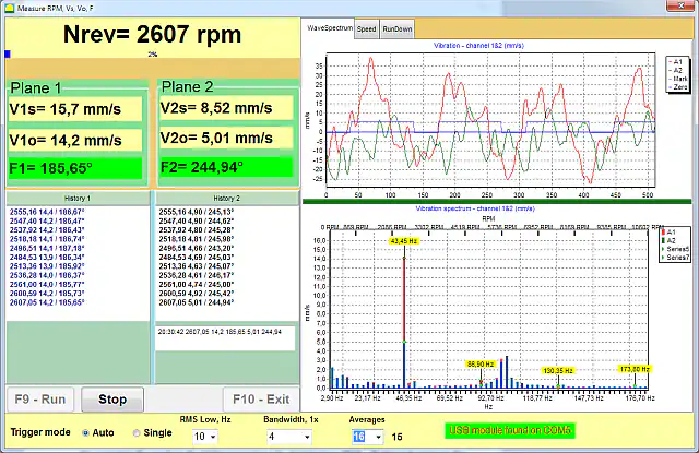
- Presione "Run#0" en el software para medir la vibración inicial
- Registre los valores de amplitud y fase de la vibración
Instalación del peso de prueba
- Detenga la bomba
- Pese un peso de prueba adecuado utilizando la báscula electrónica
- Instale el peso en el rotor en el primer plano de corrección
- Ingrese la masa del peso y el radio de instalación en el software
- Reinicie la bomba y realice la medición "Run#1"
Medición del segundo plano (para balanceo en dos planos)
- Detenga la bomba y retire el peso de prueba del primer plano
- Fije el peso de prueba al segundo plano de corrección
- Inicie la bomba y realice la medición "Run#2"
- El software calculará automáticamente los pesos de corrección requeridos
Instalación del peso de corrección
- Detenga la bomba y retire cualquier peso de prueba
- Fabrique o seleccione los pesos de corrección según el cálculo del software
- Asegure los pesos mediante soldadura, pernos o utilizando abrazaderas
- El ángulo de instalación para cada peso se mide desde la posición del peso de prueba en la dirección de rotación
Medición de verificación
- Haga funcionar la bomba a velocidad de funcionamiento
- Realice una medición de control ("RunTrim")
- Verifique que la vibración se haya reducido a niveles aceptables
- Ajuste las masas de los pesos y repita la medición si es necesario
5. Criterios de evaluación de la calidad del balanceo
Valores aceptables de vibración residual
| Categoría de bomba (ISO 10816-7) | Aceptable para operación a largo plazo (límite de la zona B), mm/s RMS | Riesgo de daño (zona D), mm/s RMS |
|---|---|---|
| Categoría I (servicio de alta confiabilidad), hasta 200 kW | ≤ 4.0 | > 6.6 |
| Categoría I (servicio de alta confiabilidad), más de 200 kW | ≤ 5.0 | > 7.6 |
| Categoría II (servicio general), hasta 200 kW | ≤ 5.1 | > 8.5 |
| Categoría II (servicio general), más de 200 kW | ≤ 6.1 | > 9.5 |
Signos de un balanceo exitoso
- Reducción del 70 al 90% de la vibración en la frecuencia rotacional de 1×
- Lecturas de fase de vibración estables y consistentes
- Ausencia de ruido inusual
- Funcionamiento suave y uniforme de la bomba
6. Recomendaciones prácticas
Frecuencia de balanceo
Balanceo programado
- Equipo nuevo: después del período inicial de rodaje
- Después de reparaciones mayores: obligatorio
- Anualmente para equipo crítico
- Cuando los niveles de vibración se duplican respecto al valor de referencia
Balanceo no programado
- Al notar vibración o ruido inusual
- Después de cualquier reemplazo del impulsor
- Si la vibración excede los niveles aceptables
- Después de una parada de emergencia
Requisitos para un balanceo de calidad
- Asegúrese de que la bomba esté en buenas condiciones mecánicas
- Verifique que la bomba esté firmemente montada sobre una cimentación estable
- Compruebe que los rodamientos no tengan juego excesivo
- Confirme la alineación adecuada entre la bomba y el motor
- Mantenga una velocidad de funcionamiento estable durante el balanceo
Documentación de resultados
- Mantenga un registro de todos los trabajos de balanceo realizados
- Guarde los informes del software Balanset-1A para cada trabajo de balanceo
- Documente la masa y la posición de los pesos de corrección instalados
- Registre los niveles finales de vibración después del balanceo (mediciones de control)
Conclusión
El dispositivo portátil Balanset-1A proporciona un balanceo efectivo de bombas hidráulicas directamente en el lugar de trabajo. La aplicación adecuada de esta tecnología permite a los usuarios:
- Reducir la vibración del equipo en un factor de 3–10
- Aumentar la vida útil de los rodamientos de 2 a 5 veces
- Reducir el consumo de energía en un 5–15%
- Prevenir fallas de emergencia
- Disminuir los costos generales de mantenimiento
El balanceo regular de bombas hidráulicas es una parte importante del sistema de mantenimiento preventivo planificado para equipos industriales.
Preguntas frecuentes (FAQ)
¿Qué es el balanceo de bombas hidráulicas?
El balanceo de bombas hidráulicas es el proceso de corregir la distribución desigual de masa en los componentes giratorios de una bomba (como el impulsor y el eje). Mediante la adición o eliminación de pequeños pesos, el objetivo es eliminar la vibración y el ruido excesivos, mejorando el rendimiento y extendiendo la vida útil de la bomba.
¿Por qué es importante balancear una bomba hidráulica?
Balancear una bomba es crucial porque una bomba desbalanceada puede causar vibración y ruido excesivos, lo que lleva a un desgaste acelerado de los rodamientos y sellos, una eficiencia reducida y un mayor riesgo de falla repentina. Un balanceo adecuado ayuda a garantizar un funcionamiento suave, eficiente y confiable de la bomba.
¿Cómo se balancea una bomba hidráulica?
El balanceo de bombas hidráulicas generalmente se realiza utilizando un dispositivo como el Balanset-1A. El proceso implica medir la vibración y la fase de la bomba, agregar un peso de prueba al rotor, medir el cambio y luego calcular e instalar un peso de corrección en una ubicación específica. Después de instalar el peso de corrección, la bomba se vuelve a ejecutar para verificar que los niveles de vibración hayan disminuido a límites aceptables.
¿Qué equipo se utiliza para el balanceo de bombas?
El balanceo de bombas requiere un sistema de medición de vibración y balanceo. El kit Balanset-1A, por ejemplo, incluye un módulo de interfaz USB, dos sensores de vibración (acelerómetros), un tacómetro láser (sensor de referencia de fase), cinta reflectante para el rotor, balanzas electrónicas para pesar los pesos de prueba y de corrección, y un software especializado que se ejecuta en una computadora portátil para guiar el procedimiento de balanceo.
¿Con qué frecuencia se debe balancear una bomba?
Las bombas deben balancearse siempre que haya una vibración significativa o después de eventos que puedan causar desbalance. Se recomienda balancear las bombas nuevas después de un período inicial de rodaje, después de reparaciones mayores o reemplazos del impulsor, y como parte del mantenimiento anual de bombas críticas. Se aconseja el balanceo no programado si aparece una vibración o ruido inusual o después de cualquier parada de emergencia.
¿Cuáles son los niveles de vibración aceptables para una bomba balanceada?
Los niveles de vibración aceptables dependen de la categoría y la potencia de la bomba. La norma ISO 10816-7 (bombas rotodinámicas superiores a 1 kW) establece los límites de la zona B — aceptables para una operación a largo plazo sin restricciones — de 4.0 mm/s (RMS) para bombas de Categoría I (alta confiabilidad) de hasta 200 kW y de 5.0 mm/s para más de 200 kW; para bombas de Categoría II de servicio general, los límites son de 5.1 mm/s hasta 200 kW y de 6.1 mm/s para más de 200 kW. Una vibración por encima del límite de las zonas C/D (6.6–9.5 mm/s dependiendo de la categoría y la potencia) indica un riesgo de daño y requiere atención inmediata.
¿El balanceo soluciona todos los problemas de vibración?
No. El balanceo aborda la vibración causada por el desbalance de masa del rotor. Reducirá significativamente las vibraciones en la frecuencia de rotación, pero no puede solucionar otras fuentes de vibración como la desalineación, rodamientos desgastados, ejes curvados u otros problemas mecánicos. Esos problemas deben diagnosticarse y repararse por separado.

Nikolai Shelkovenko
Nikolai Shelkovenko es ingeniero en análisis de vibraciones y fundador y director general de Vibromera. Desde hace más de 15 años balancea equipos rotativos en campo y no en un banco de pruebas: desbrozadoras, ventiladores industriales, trituradoras, centrífugas, ejes y husillos. De ese trabajo nacieron los instrumentos Balanset — se concibieron como una herramienta que el especialista puede llevar hasta la máquina y usar solo, en sitio, y no como equipo de laboratorio. Vibromera se fundó en 2017 y desde 2023 tiene su sede en Oporto, Portugal. Aquí se realizan el desarrollo, el ensamblaje y el soporte de la línea Balanset. El instrumento insignia es el Balanset-1A, un analizador portátil para el balanceo en uno y dos planos y para el diagnóstico de vibraciones. Nikolai participa personalmente en la atención al cliente, en la resolución de casos difíciles de balanceo y en el desarrollo del software. Trabaja con clientes de todo el mundo, en cualquier idioma.

