Field Dynamic Balancing
Part I: Theoretical and Regulatory Foundations of Dynamic Balancing
Field dynamic balancing is one of the key operations in vibration commissioning and condition-based maintenance, aimed at extending the service life of industrial equipment and preventing emergency situations. The use of portable instruments such as Balanset-1A allows these operations to be performed directly at the operating site, minimizing downtime and costs associated with dismantling. However, successful balancing requires not only the ability to work with the instrument, but also a deep understanding of the physical processes underlying vibration, as well as knowledge of the regulatory framework governing the quality of work.
The methodology principle is based on installing trial weights and calculating unbalance influence coefficients. Simply put, the instrument measures the vibration (amplitude and phase) of a rotating rotor, after which the user sequentially adds small trial weights in specific planes to "calibrate" the influence of additional mass on vibration. Based on changes in vibration amplitude and phase, the instrument automatically calculates the necessary mass and installation angle of corrective weights to eliminate unbalance.
This approach implements the so-called three-run method for two-plane balancing: initial measurement and two runs with trial weights (one in each plane). For single-plane balancing, two runs are usually sufficient - without weight and with one trial weight. In modern instruments, all necessary calculations are performed automatically, significantly simplifying the process and reducing operator qualification requirements.
Section 1.1: Physics of Unbalance: In-Depth Analysis
At the core of any vibration in rotating equipment lies imbalance, or unbalance. Unbalance is a condition where the rotor mass is unevenly distributed relative to its axis of rotation. This uneven distribution leads to the occurrence of centrifugal forces, which in turn cause vibration of supports and the entire machine structure. The consequences of unaddressed unbalance can be catastrophic: from premature wear and destruction of bearings to damage to the foundation and the machine itself. For effective diagnosis and elimination of unbalance, it is necessary to clearly distinguish its types.
Types of Unbalance
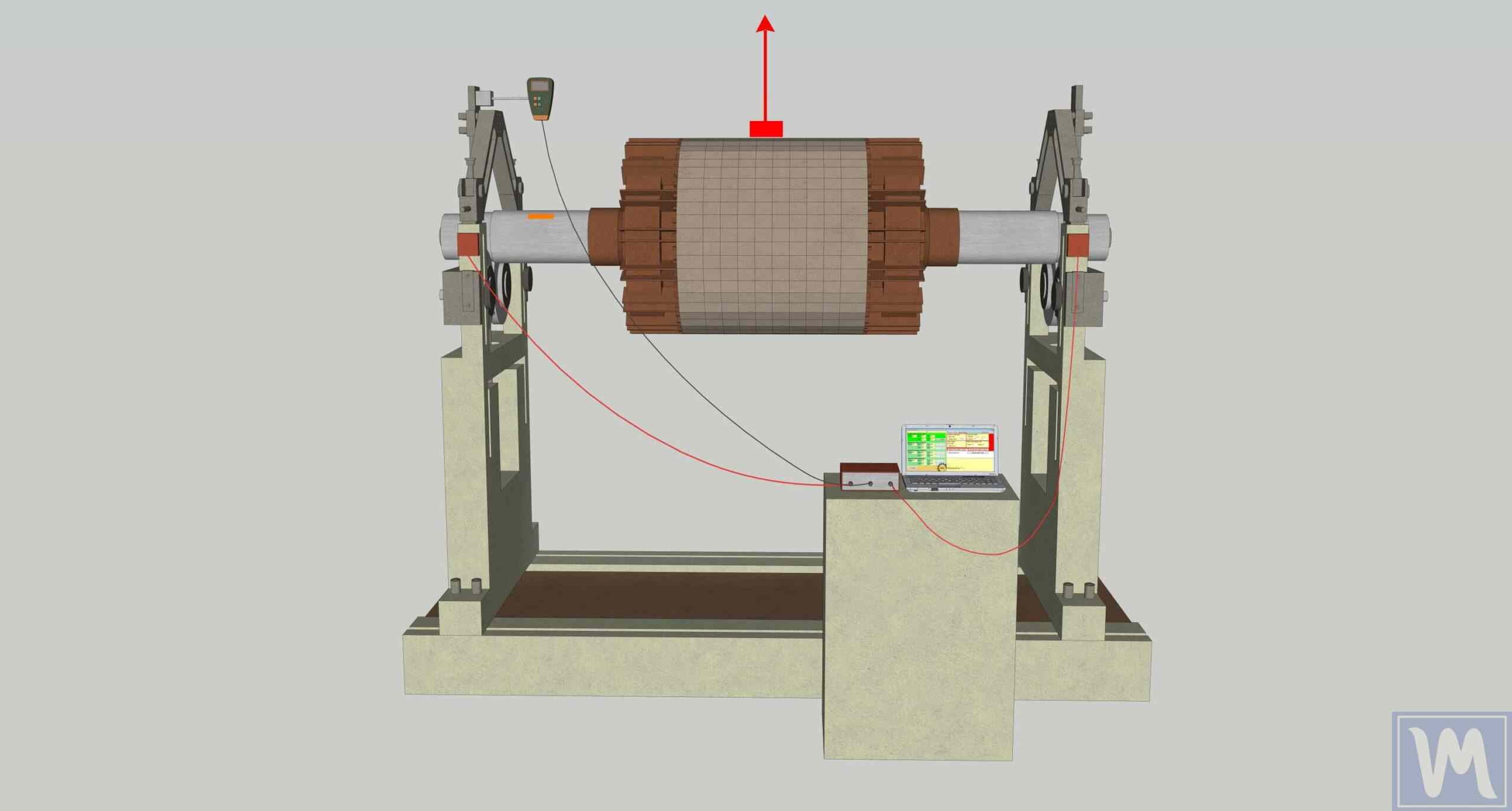
Static unbalance (single-plane): In this type of unbalance the rotor's central principal axis of inertia is displaced parallel to the axis of rotation - the center of mass is offset radially from the rotation axis. In a static state, such a rotor, installed on horizontal knife-edges (parallel ways), will always turn with the heavy side downward. Static unbalance is dominant for thin, disk-shaped rotors where the length-to-diameter ratio (L/D) is below approximately 0.5, for example, grinding wheels or narrow fan impellers. Static unbalance elimination is possible by installing one corrective weight in one correction plane, diametrically opposite to the heavy point - a single-plane approach that is valid at moderate speeds (roughly under 1000 rpm); high-speed narrow discs still require two-plane balancing.
Couple (moment) unbalance: This type occurs when the principal axis of inertia of the rotor intersects the axis of rotation at the center of mass but is not parallel to it. Couple unbalance can be represented as two equal in magnitude but oppositely directed unbalanced masses located in different planes. In a static state, such a rotor is in equilibrium, and the unbalance manifests only during rotation in the form of "rocking" or "wobbling". To compensate for it, installation of at least two corrective weights in two different planes is required, creating a compensating moment.
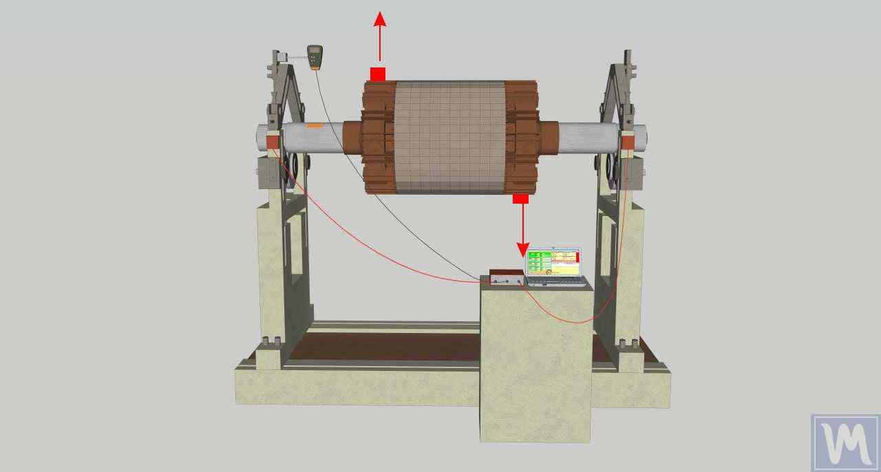
Dynamic unbalance: This is the most common type of unbalance in real conditions, representing a combination of static and couple unbalances. In this case, the principal central axis of inertia of the rotor does not coincide with the axis of rotation and does not intersect it at the center of mass. To eliminate dynamic unbalance, mass correction in at least two planes is necessary. Two-channel instruments such as Balanset-1A are designed specifically to solve this problem.
Quasi-static unbalance: This is a special case of dynamic unbalance where the principal axis of inertia intersects the axis of rotation but not at the rotor's center of mass. This is a subtle but important distinction for diagnosing complex rotor systems.
Rigid and Flexible Rotors: Critical Distinction
One of the fundamental concepts in balancing is the distinction between rigid and flexible rotors. This distinction determines the very possibility and methodology of successful balancing.
Rigid rotor: A rotor is considered rigid if its operating rotation frequency is significantly lower than its first critical frequency, and it does not undergo significant elastic deformations (deflections) under the action of centrifugal forces. Balancing such a rotor is typically successfully performed in two correction planes. Balanset-1A instruments are primarily designed for working with rigid rotors.
Flexible rotor: A rotor is considered flexible if it operates at a rotation frequency close to one of its critical frequencies or exceeding it. In this case, elastic shaft deflection becomes comparable to the center of mass displacement and itself contributes significantly to overall vibration.
Attempting to balance a flexible rotor using the methodology for rigid rotors (in two planes) often leads to failure. Installing corrective weights may compensate for vibration at low, sub-resonant speed, but when reaching operating speed, when the rotor bends, these same weights may increase vibration by exciting one of the bending vibration modes. This is one of the key reasons why balancing "doesn't work", although all actions with the instrument are performed correctly.
Before starting work, it is extremely important to classify the rotor by correlating its operating speed with known (or calculated) critical frequencies. If it's impossible to bypass resonance, it is recommended to temporarily change the unit's mounting conditions during balancing to shift the resonance.
Section 1.2: Regulatory Framework: ISO Standards
Standards in the field of balancing perform several key functions: they establish unified technical terminology, define quality requirements, and importantly, serve as the basis for compromise between technical necessity and economic feasibility.
ISO 21940-11 (formerly ISO 1940-1): Quality Requirements for Balancing Rigid Rotors
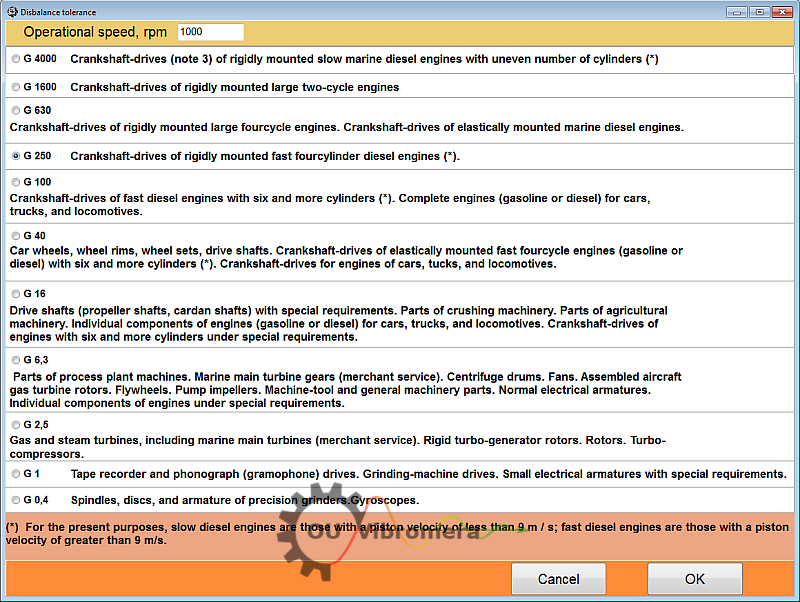
This standard is the fundamental document for determining permissible residual unbalance. It introduces the concept of balance quality grade (G), which is chosen by machine type only. The speed enters later, when the grade is converted into a permissible specific unbalance: eper = (G × 9549) / n.
Quality grade G: Each type of equipment corresponds to a specific quality grade that remains constant regardless of rotation speed. For example, grade G6.3 is recommended for fans, pumps and general-purpose electric motors, G16 for crushers and agricultural machinery, and G2.5 for turbines and turbo-compressors.
Calculation of permissible residual unbalance (Uper): The standard allows calculation of a specific permissible unbalance value that serves as a target indicator during balancing. The calculation is performed in three stages:
- Determination of permissible specific unbalance (eper) using the formula:
eper = (G × 9549) / n
where G is the balancing quality grade (e.g., 2.5), n is the operating rotation frequency, rpm. The unit of measurement for eper is g·mm/kg or μm. - Determination of permissible residual unbalance (Uper) for the entire rotor:
Uper = eper × M
where M is the rotor mass, kg. The unit of measurement for Uper is g·mm. - Allocation of Uper between the two correction planes. For a symmetric rotor, split it 50/50 (in the example below: 19.9 g·mm per plane). For an asymmetric between-bearing rotor: Uleft = Uper × (b/L), Uright = Uper × (a/L), where a and b are the distances from the center of mass to the left and right bearings and L = a + b. Overhung rotors require a moment-based recalculation with a tighter tolerance on the overhung plane. Balanset-1A performs this allocation automatically and shows the per-plane residual unbalance (D1, D2) next to the balancing tolerance on the Result tab.
Example: For an electric motor rotor with a mass of 5 kg, operating at 3000 rpm with quality grade G2.5:
eper = (2.5 × 9549) / 3000 ≈ 7.96 μm
Uper = 7.96 × 5 = 39.8 g·mm
This means that after balancing, the residual unbalance should not exceed 39.8 g·mm - for this symmetric rotor, about 19.9 g·mm in each of the two correction planes.
ISO 20806:2009: Criteria and Safeguards for In-Situ Balancing of Medium and Large Rotors
This standard directly regulates the field balancing process.
Advantages: The main advantage of balancing in place is that the rotor is balanced in real operating conditions, on its supports and under operating load. This automatically accounts for the dynamic properties of the support system and the influence of connected shaft train components.
Disadvantages and limitations:
- Limited access: Often access to correction planes on an assembled machine is difficult, limiting possibilities for weight installation.
- Need for trial runs: The balancing process requires several "start-stop" cycles of the machine.
- Difficulty with severe unbalance: In cases of very large initial unbalance, limitations on plane selection and corrective weight mass may not allow achieving the required balancing quality.
Part II: Practical Guide to Balancing with Balanset-1A Instruments
The success of balancing depends overwhelmingly on the thoroughness of preparatory work. Most failures are related not to instrument malfunction, but to ignoring factors affecting measurement repeatability. The main preparation principle is to exclude all other possible sources of vibration so that the instrument measures only the effect of unbalance.
Section 2.1: Foundation of Success: Pre-balancing Diagnostics and Machine Preparation
Step 1: Primary Vibration Diagnostics (Is it really unbalance?)
Before balancing, it is useful to perform a preliminary vibration measurement in vibrometer mode. The Balanset-1A software has a "Vibration Meter" mode (F5 button) where you can measure overall vibration and separately the component at rotation frequency (1×) before installing any weights.
Classic unbalance sign: The vibration spectrum should be dominated by a peak at the rotor's rotational frequency (peak at 1x RPM frequency). The amplitude of this component in horizontal and vertical directions should be comparable, and amplitudes of other harmonics should be significantly lower.
Signs of other defects: If the spectrum contains significant peaks at other frequencies (e.g., 2x, 3x RPM) or at non-multiple frequencies, this indicates the presence of other problems that must be eliminated before balancing.
Step 2: Comprehensive Mechanical Inspection (Checklist)
- Rotor: Thoroughly clean all rotor surfaces from dirt, rust and built-up deposits (caked product). Even a small amount of dirt at a large radius creates significant unbalance. Check for absence of broken or missing elements.
- Bearings: Check bearing assemblies for excessive play, extraneous noise, and overheating. Worn bearings will not allow obtaining stable readings.
- Foundation and frame: Ensure that the unit is installed on a rigid foundation. Check the torque of the anchor bolts and the absence of cracks in the frame.
- Drive: For belt drives, check belt tension and condition. For coupling connections - shaft alignment.
- Safety: Ensure the presence and serviceability of all protective guards.
Section 2.2: Instrument Setup and Configuration
Hardware Installation
Vibration sensors (accelerometers):
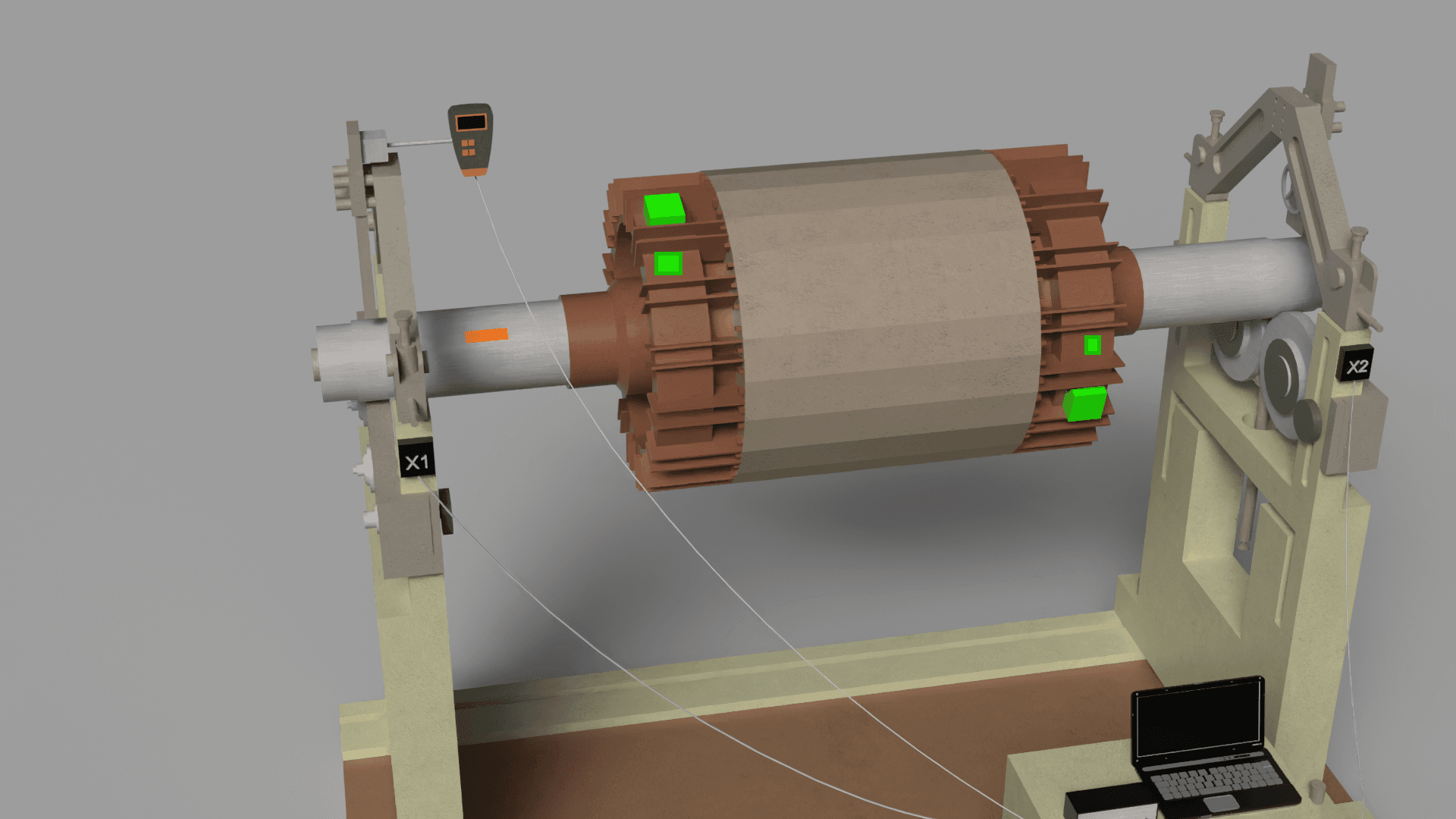
- Connect sensor cables to corresponding instrument connectors (e.g., X1 and X2 for Balanset-1A; on newer revisions the connectors are labeled Ch-1 and Ch-2).
- Install sensors on bearing housings as close to the rotor as possible.
- Key practice: To obtain maximum signal, sensors should be installed in the direction where vibration is maximum. Use a powerful magnetic base or threaded mount to ensure rigid contact.
Phase sensor (laser tachometer):
- Connect the sensor to the special input (X3 for Balanset-1A; labeled Tacho on newer revisions).
- Attach a small piece of reflective tape to the shaft or other rotating part of the rotor.
- Install the tachometer so that the laser beam stably hits the mark throughout the entire revolution.
Software Configuration (Balanset-1A)
- Launch the software and connect the USB interface module (administrator rights are not required).
- Go to the balancing module (F7 - Balancing). Create a new record for the unit being balanced.
- Select balancing type: 1-plane (static, the F2 - Single-plane tab) for narrow rotors or 2-plane (dynamic, the F3 - Two-plane tab) for most other cases.
- Define correction planes: choose places on the rotor where corrective weights can be safely installed.
Section 2.3: Balancing Procedure: Step-by-Step Guide
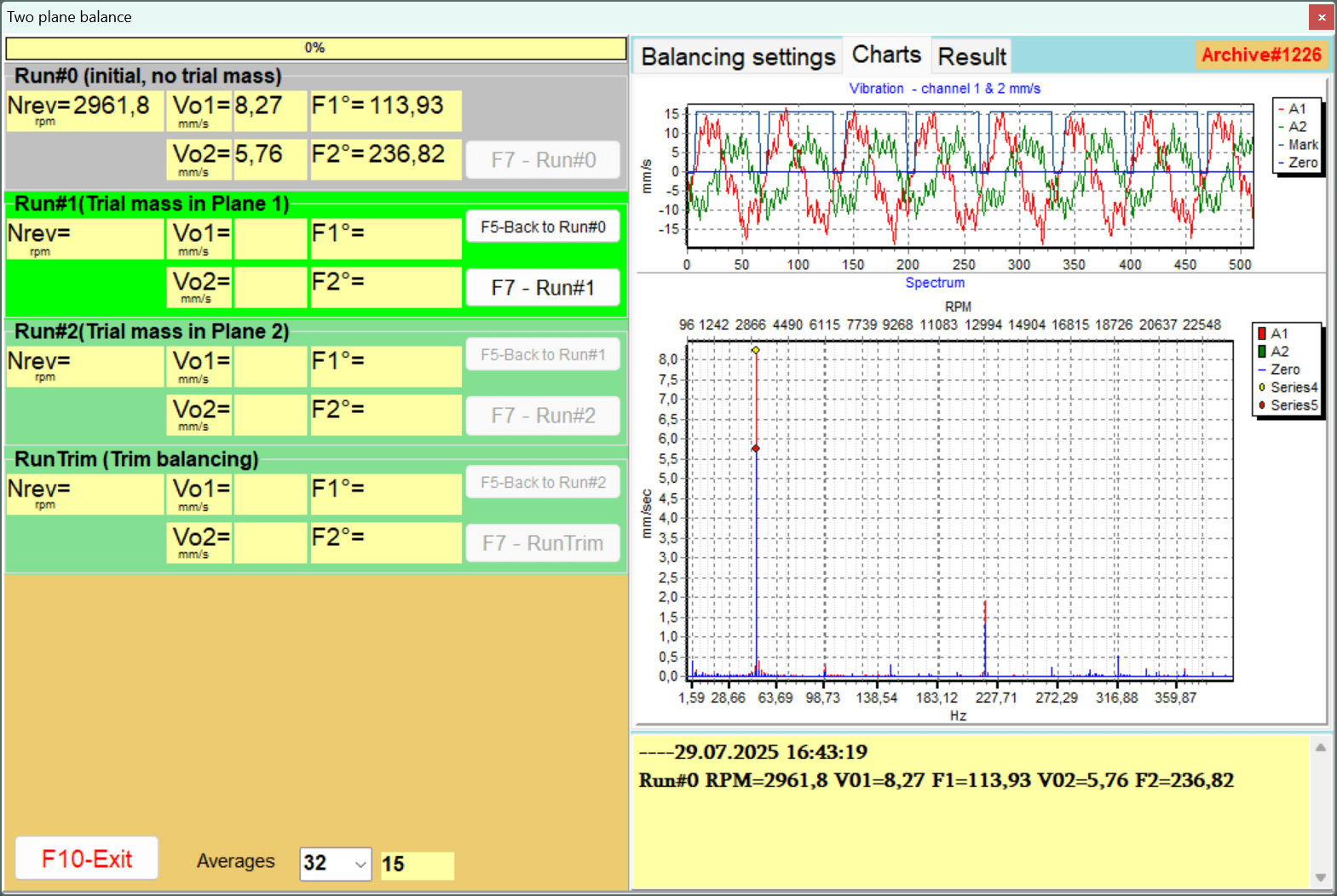
Run 0: Initial measurement
- Start the machine and bring it to stable operating speed. It is extremely important that the rotation speed is the same in all subsequent runs.
- In the program, start measurement. The instrument will record initial vibration amplitude and phase values.
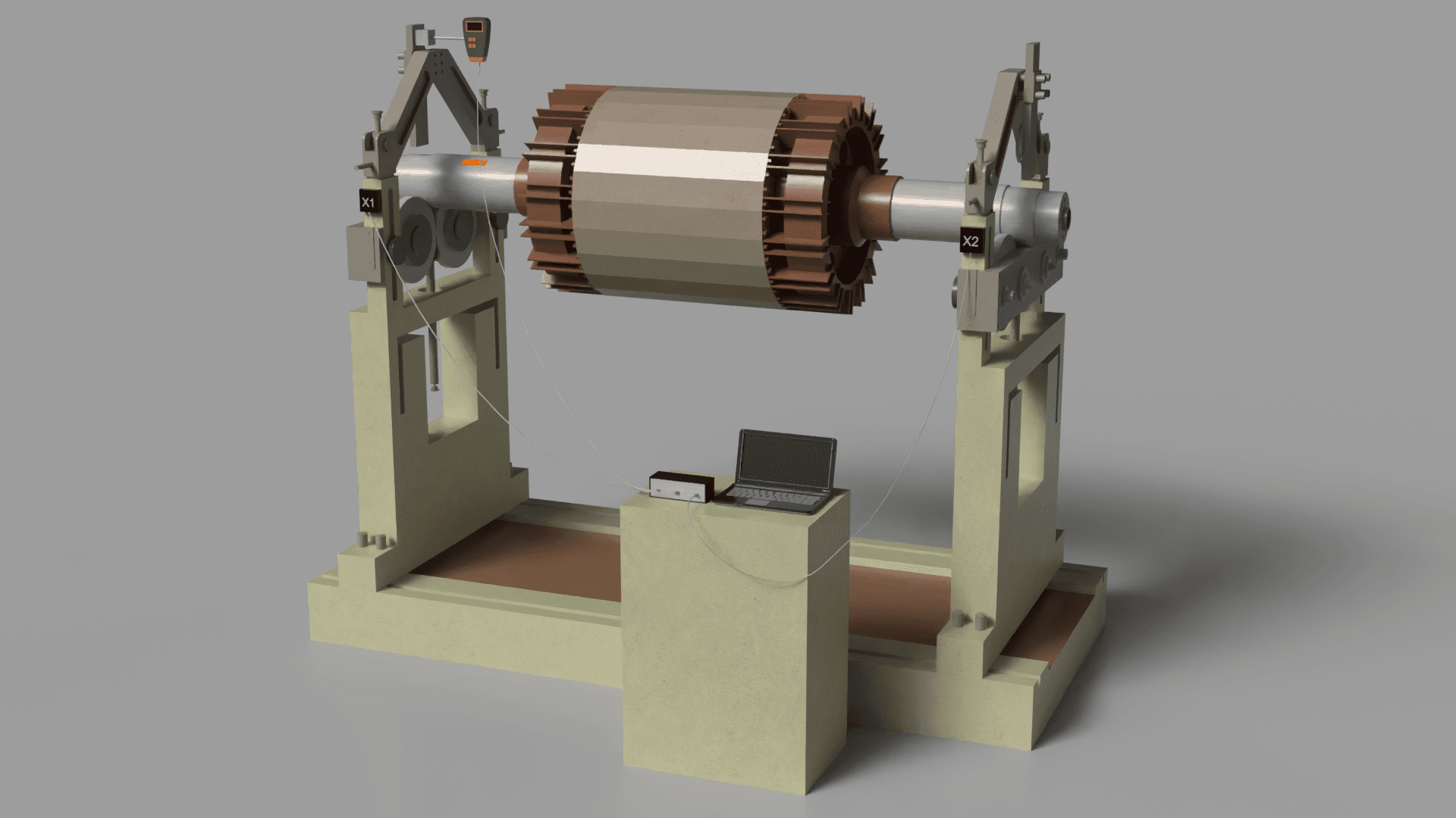
Run 1: Trial weight in plane 1
- Stop the machine.
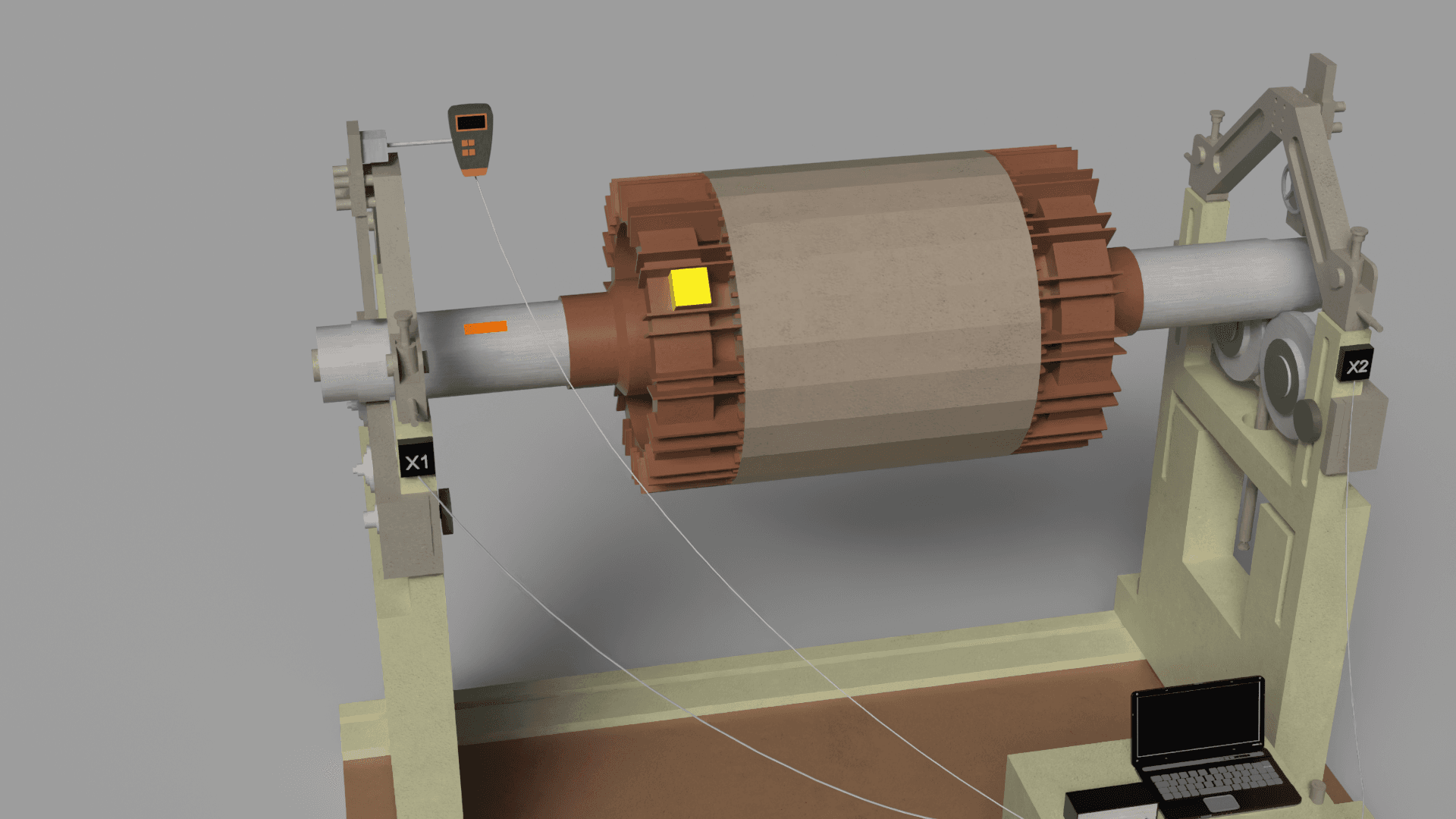
- Trial weight selection: The trial weight mass should be sufficient to cause noticeable change in vibration parameters (amplitude change of at least 20-30% OR phase change of at least 20-30 degrees). You do not have to guess the starting mass: after Run 0 the software's First Trial Weight Estimator recommends both the trial weight mass and its installation angle from the tachometer mark, and the program warns if the installed weight turns out to be too small.
- Trial weight installation: Securely attach the weighed trial weight at a known radius in plane 1. Record the angular position.
- Start the machine at the same stable speed.
- Perform the second measurement.
- Stop the machine and remove the trial weight. If removing it is impractical, you can leave it installed - check the "Leave on rotor" box in the software so the calculation accounts for it.
Run 2: Trial weight in plane 2 (for 2-plane balancing)
- Repeat exactly the procedure from step 2, but install the trial weight in plane 2.
- Start, measure, stop and remove the trial weight (or leave it with the "Leave on rotor" box checked, as in Run 1).
Calculation and installation of corrective weights
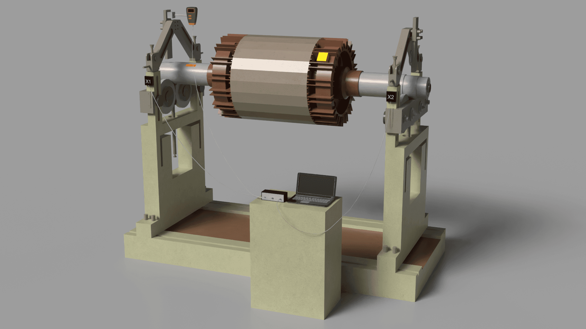
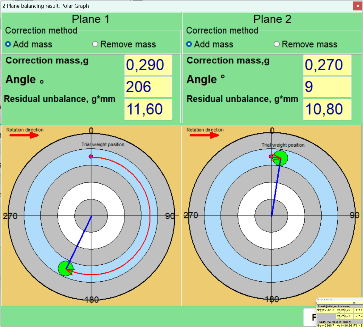
- Based on vector changes recorded during trial runs, the program will automatically calculate the mass and installation angle of the corrective weight for each plane.
- The installation angle is usually measured from the trial weight location in the direction of rotor rotation.
- Securely attach permanent corrective weights. When using welding, remember that the weld itself also has mass.
Run T (Trim): Verification measurement and fine balancing
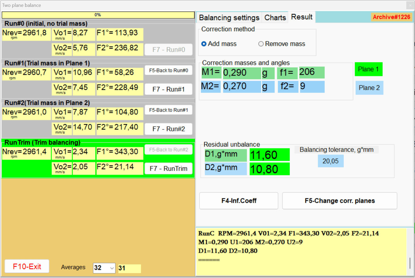
- Start the machine again.
- Perform a control measurement to assess the level of residual vibration.
- Compare the obtained value with the tolerance calculated according to ISO 1940-1.
- If vibration still exceeds the tolerance, the instrument will calculate a small "fine" (trim) correction.
- Upon completion, save the report and influence coefficients for possible future use.
Part III: Advanced Problem Solving and Troubleshooting
This section is devoted to the most complex aspects of field balancing - situations where the standard procedure does not produce results.
Safety Measures
Prevention of accidental start (Lockout/Tagout): Before starting work, de-energize and disconnect the rotor drive. Hang warning tags on the starters so that no one starts the machine by mistake.
Personal protective equipment: Safety glasses or protective face shield are mandatory. Clothing should be tight-fitting, without loose edges. Long hair should be tucked under a head covering.
Danger zone around the machine: Limit access of unauthorized persons to the balancing zone. During test runs, barriers or warning tapes are installed around the unit. The danger zone radius is at least 3-5 meters.
Reliable weight attachment: When attaching trial or permanent corrective weights, pay special attention to their fixation. An ejected weight becomes a dangerous projectile.
Electrical safety: Observe general electrical safety measures - use a serviceable grounded outlet, don't route cables through wet or hot zones.
Section 3.1: Diagnosis and Overcoming Measurement Instability
Symptom: During repeated measurements under identical conditions, amplitude and/or phase readings change significantly ("float", "jump"). This makes correction calculation impossible.
Root cause: The instrument is not malfunctioning. It accurately reports that the system's vibrational response is unstable and unpredictable.
Systematic diagnostic algorithm:
- Mechanical looseness: This is the most frequent cause. Check tightening of bearing housing mounting bolts, frame anchor bolts. Check for cracks in foundation or frame.
- Bearing defects: Excessive internal clearance in rolling bearings or bearing shell wear allows the shaft to move chaotically inside the support.
- Process-related instability:
- Aerodynamic (fans): Turbulent airflow, flow separation from blades can cause random force effects.
- Hydraulic (pumps): Cavitation creates powerful, random hydraulic shocks that mask the periodic signal from unbalance.
- Internal mass movement (crushers, mills): Material can redistribute inside the rotor, acting as "mobile unbalance".
- Resonance: If operating speed is very close to the structure's natural frequency, even slight speed variations cause huge changes in vibration amplitude and phase.
- Thermal effects: As the machine warms up, thermal expansion can cause shaft bending or alignment changes.
Section 3.2: When Balancing Doesn't Help: Identifying Root Defects
Symptom: The balancing procedure has been performed, readings are stable, but final vibration remains high.
Using the vibration spectrum for differential diagnosis (in the Balanset software: F8 - Charts, "F5-Spectrum (Hz)" tab):
- Shaft misalignment: Main sign - high vibration peak at 2x RPM frequency. High axial vibration is characteristic.
- Rolling bearing defects: Manifest as high-frequency vibration at characteristic "bearing" frequencies (BPFO, BPFI, BSF, FTF). Note that detailed rolling-bearing diagnostics is beyond the scope of Balanset-1A: the instrument measures vibration velocity in the 5-1000 Hz band, the sensor response rolls off above roughly 550 Hz, and there is no envelope (demodulation) analysis - use a dedicated bearing analyzer for that task.
- Shaft bow: Manifests as high peak at 1x RPM but often accompanied by noticeable component at 2x RPM. When the rotor is balanced on a mandrel, the software offers built-in runout compensation: the F7 - Run Ecc measurement (taken with the rotor turned 180 degrees on the mandrel) together with the "Subtract mandrel runout from measurements" option, so eccentricity is not mistaken for unbalance.
- Electrical problems (electric motors): Magnetic field asymmetry can cause vibration at twice the supply frequency (100 Hz for 50 Hz network).
Common Balancing Errors and Prevention Tips
- Balancing a faulty or dirty rotor: Always check the mechanism's condition before balancing.
- Trial weight too small: Aim for the 20-30% vibration change rule.
- Inconsistent operating speed between runs: Always maintain stable and identical rotation speed during all measurements.
- Phase and mark errors: Carefully monitor angle determination. The corrective weight angle is usually measured from the trial weight position in the direction of rotation.
- Incorrect attachment or loss of weights: Strictly follow the methodology - remove the trial weight after the run, or, if it stays on the rotor, make sure the "Leave on rotor" box is checked so the calculation accounts for it.
Balancing Quality Standards
| Quality Grade G | Balance quality grade G = eper·ω (mm/s) | Rotor Types (Examples) |
|---|---|---|
| G4000 | 4000 | Rigidly mounted crankshafts of slow marine diesel engines |
| G1600 | 1600 | Crankshafts of large two-stroke engines |
| G16 | 16 | Cardan shafts with special requirements, agricultural machinery, crushers |
| G6.3 | 6.3 | Pump rotors, fan impellers, electric motor armatures |
| G2.5 | 2.5 | Gas and steam turbine rotors, turbo-compressors, machine tool drives |
| G1 | 1 | Grinding machine drives, spindles |
| G0.4 | 0.4 | Precision grinding machine spindles, gyroscopes |
Note: the grade number is the product eper·ω in mm/s. The permissible specific unbalance itself is speed-dependent: eper = (G × 9549) / n [μm]. Example: G6.3 at 1500 rpm gives eper = 40.1 μm; at 3000 rpm it gives 20.1 μm.
| Defect Type | Dominant Spectrum Frequency | Phase Characteristic | Other Symptoms |
|---|---|---|---|
| Unbalance | 1x RPM | Stable | Radial vibration predominates |
| Shaft misalignment | 1x, 2x, 3x RPM | May be unstable | High axial vibration - key sign |
| Mechanical looseness | 1x, 2x and multiple harmonics | Unstable, "jumping" | Visually noticeable movement |
| Rolling bearing defect | High frequencies (BPFO, BPFI, etc.) | Not synchronized with RPM | Extraneous noise, elevated temperature |
| Resonance | Operating speed coincides with natural frequency | Phase changes 180° when passing through resonance | Vibration amplitude sharply increases at specific speed |
Part IV: Frequently Asked Questions and Application Notes
Section 4.1: General Frequently Asked Questions (FAQ)
When should I use 1-plane vs 2-plane balancing?
Use 1-plane (static) balancing for narrow, disk-shaped rotors where the length-to-diameter ratio (L/D) is below approximately 0.5 and the speed is moderate (roughly under 1000 rpm), such as grinding wheels or narrow fan impellers. Use 2-plane (dynamic) balancing for elongated rotors, for any L/D above approximately 0.5, and for high-speed narrow discs. Two-plane balancing corrects both static unbalance and couple (moment) unbalance.
What should I do if the trial weight causes dangerous vibration increase?
Immediately stop the machine. This indicates the trial weight was installed close to the existing heavy point, aggravating the unbalance. The solution is to move the trial weight 180 degrees from its original position and repeat the measurement. This ensures the trial weight creates an opposing effect rather than adding to the existing imbalance.
Can I use saved influence coefficients for a different machine?
Yes, but only if the machines are absolutely identical - same model, same rotor, same foundation, same bearings. Any change in structural stiffness will change the influence coefficients and make them invalid. Best practice is to always conduct new trial runs for each new machine to ensure accurate correction calculations.
What is the difference between static and dynamic unbalance?
In static unbalance the rotor's central principal axis of inertia is displaced parallel to the rotation axis - the center of mass is offset radially from the axis - and it can be detected without spinning by placing the rotor on knife-edge supports. Dynamic unbalance is a combination of static and couple unbalance where the principal axis of inertia doesn't coincide with the rotation axis - it only manifests during rotation and requires two-plane correction.
Why are my balancing readings unstable (floating)?
Unstable readings indicate the system's vibrational response is unpredictable. Common causes include: mechanical looseness (loose bolts, cracks), worn bearings with excessive play, process instability (cavitation in pumps, turbulence in fans), resonance (operating speed near natural frequency), thermal effects during warm-up, or vibration from neighboring equipment. Address these issues before attempting to balance.
What is the three-run method in two-plane balancing?
The three-run method involves: Run 0 - initial measurement without any trial weights to establish baseline vibration; Run 1 - measurement with trial weight installed in Plane 1 to determine its influence; Run 2 - measurement with trial weight moved to Plane 2. Based on these three data points, the instrument calculates the exact corrective weights needed for both planes using the influence coefficient method.
How do I calculate permissible residual unbalance according to ISO 1940-1?
First calculate permissible specific unbalance: eper = (G × 9549) / n, where G is the quality grade (e.g., 2.5 for turbines, 6.3 for fans) and n is RPM. Then calculate permissible residual unbalance: Uper = eper × M, where M is rotor mass in kg. For example, a 5 kg rotor at 3000 RPM with G2.5: eper = (2.5 × 9549)/3000 = 7.96 μm, Uper = 7.96 × 5 = 39.8 g·mm.
What is the minimum trial weight effect needed for accurate balancing?
The trial weight should cause at least 20-30% change in vibration amplitude OR 20-30 degrees change in phase angle. If the effect is too small, the useful signal drowns in measurement noise, leading to inaccurate correction calculations. If nothing changes, increase trial weight mass (within safe limits) until you achieve sufficient effect.
How do I account for keyways? (ISO 8821, now ISO 21940-32:2012)
Standard practice is to use a "half-key" in the shaft keyway when balancing without the mating part, as specified in ISO 21940-32:2012 (which superseded ISO 8821). This compensates for the mass of that part of the key that fills the groove on the shaft.
| Symptom | Probable Causes | Recommended Actions |
|---|---|---|
| Unstable/"floating" readings | Mechanical looseness, bearing wear, resonance, process instability, external vibration | Tighten all bolted connections, check bearing play, conduct coast-down test (the RunDown tab in the F5 - Vibration Meter mode), stabilize operating regime |
| Cannot achieve tolerance after several cycles | Incorrect influence coefficients, rotor is flexible, presence of hidden defect (misalignment) | Repeat trial run with properly selected weight, check if rotor is flexible, use FFT to search for other defects |
| Vibration normal after balancing but quickly returns | Corrective weight ejection, product buildup on rotor, thermal deformations | Use more reliable weight attachment (welding), implement regular rotor cleaning schedule |
Section 4.2: Balancing Guide for Specific Equipment Types
Industrial fans and induced-draft (ID) fans:
- Problem: Most susceptible to unbalance due to product buildup on blades or abrasive wear.
- Procedure: Always thoroughly clean the impeller before starting work. Pay attention to aerodynamic forces that can cause instability.
Pumps:
- Problem: Main enemy - cavitation.
- Procedure: Before balancing, ensure sufficient cavitation margin at inlet (NPSHa). Check that suction pipeline is not clogged.
Crushers, grinders and mulchers:
- Problem: Extreme wear, possibility of large unbalance changes due to hammer breakage or wear.
- Procedure: Check integrity and attachment of working elements. Additional machine frame anchoring may be required.
Electric motor armatures:
- Problem: May have both mechanical and electrical vibration sources.
- Procedure: Use the vibration spectrum (F8 - Charts) to check for vibration at twice the supply frequency. Its presence indicates electrical malfunction, not unbalance.
Conclusion
Dynamic balancing of rotors in place using portable instruments such as Balanset-1A is a powerful tool for increasing reliability and efficiency of industrial equipment operation. However, the success of this procedure depends not so much on the instrument itself as on specialist qualification and ability to apply a systematic approach.
Key principles:
- Preparation determines result: Thorough rotor cleaning, checking bearing and foundation condition, and preliminary vibration diagnostics are mandatory conditions for successful balancing.
- Standard compliance is the basis of quality: Application of ISO 1940-1 transforms subjective assessment into objective, measurable and legally significant result.
- The instrument is not only a balancer but also a diagnostic tool: Inability to balance or reading instability are important diagnostic signs indicating more serious problems.
- Understanding process physics is key to solving non-standard tasks: Knowledge of differences between rigid and flexible rotors, understanding resonance influence allows specialists to make correct decisions.
Following the recommendations outlined in this guide will allow technical specialists not only to successfully cope with typical tasks but also effectively diagnose and solve complex, non-trivial problems of rotating equipment vibration.

