Контактсіз сызықтық орын ауыстыру датчиктері арқылы ротордың салыстырмалы дірілін өлшеу
With the Балансет-1А салыстырмалы мәнді өлшеуге болады vibration of the ротор контактсіз сызықтық энкодерлер арқылы.
1.1 Датчик түрін таңдау және баптау
Тапсырмаға байланысты өлшемдер үшін діріл датчиктері немесе орын ауыстыру датчиктері пайдаланылуы мүмкін. Датчик түрін таңдау үшін негізгі терезенің төменгі жағындағы “Датчик түрі” тақтасында “Vibro” немесе “Linear” өрісіне белгі қою қажет.
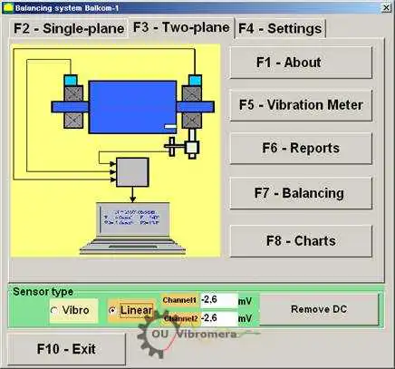
Fig. 1. The main working window of the Balanset program.T
Before starting the measurement it is necessary to make sure that the conversion coefficients of the sensors are set correctly. For this purpose press the button “F4-Settings” in the main working window of the program (see Fig. 1) and go to the settings window designed for entering conversion coefficients (see Fig. 2).
In the working window shown in Fig. 2, in the corresponding fields the conversion coefficients of linear and vibration sensors should be entered. These coefficients are specified in the instrument passport. Usually you do not need to change them.
For the linear displacement Balanset-1A аспабының жинағына кіретін датчиктердің түрлендіру коэффициенттері тиісінше мынаған тең:
- Kprl1= 0.94 mV/μm (conversion coefficient of the sensor of the 1st channel);
- Kprl2 = 0.94 mV/μm (conversion coefficient of the sensor of the 2nd channel.
For proper operation, the linear encoder must be installed at a certain distance from the surface of the object of measurement. The nominal clearance between the surface and the end of the sensor is 3.5 mm. In this case there is a constant voltage of 2.48 volts at the sensor output. This voltage will be shown in the fields “Channel1” and “Channel2” for the first and second channels respectively.
To compensate it you must press the button “Remove DC”. A small residual offset will not interfere with the measurement.
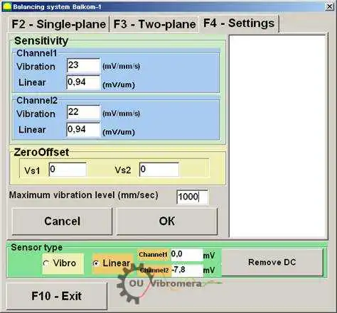
Fig. 2. Working window for entering conversion coefficients and selecting the type of used sensors
Attention! Номиналды саңылаудың және сызықтық энкодерлердің түрлендіру коэффициенттерінің көрсетілген мәндері болат роторлар үшін берілген. Басқа металдардан (мыс, қола, алюминий) жасалған роторлар үшін номиналды саңылау мен датчиктердің түрлендіру коэффициенттерін пайдаланушы калибрлеу жүргізу арқылы тәжірибелік жолмен анықтауы тиіс.
To save the changed parameters press “OK” button. The new parameters will be saved in a file and used for further measurements.
1.2 Ротордың радиалды дөңгелексіздігін өлшеу
Ротордың радиалды дөңгелексіздігін контактсіз жуықтау сенсорлары 3-суретте көрсетілген схема бойынша екі жазықтықта өлшеуге болады. Уақыт функциясын және ротор дөңгелексіздігінің спектрін өлшеу мен тұрғызу үшін, қажет болған жағдайда, бірқатар дайындық операцияларын орындау керек, соның ішінде:
- – select diametrical sections of the rotor, in which the measurements will be carried out;
- контактсіз сызықтық орын ауыстыру датчиктері 5 пен 6-ны және phase бұрыш датчигі 7-ні арнайы құрылғылар (мысалы, магниттік штативтер) арқылы машина рамасына орнату;
- – connect proximity sensors of linear motion to connectors X1 and X2, and phase angle sensor to connector X3 of the measuring unit;
- – set a nominal measuring gap ∆ between the rotor surface and the sensing element for each linear encoder (for the rotor made of steel ∆ = 3.5 mm);
- – place on the rotor the reflective mark required for triggering for the phase angle sensor 7 and check the sensor triggering;
- өлшеу блогын компьютерге қосу.
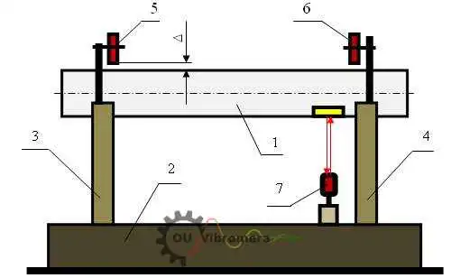
Fig. 3. Measuring the radial run-out of the rotor
If you press the button “F8 – Charts” in the main working window (see Fig. 1), the computer display shows the working window “Graphs” (see Fig. 5), designed to build different kinds of graphs of radial run-out of the rotor.
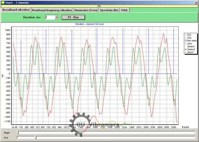
Fig. 5. The working window of the “Charts” mode
Осы терезедегі батырмалар келесі графиктерді тұрғызады:
- When you press the “Broadband vibration” button in this window, the time function of the rotor radial runout is displayed.
- If the “Rotation frequency vibration” button is pressed, the time function of the reciprocal component of the rotor radial runout is displayed.
- If you press the button “Harmonics (1/rev)”, the display will show a decomposition graph of the rotor runout into a harmonic series. The first harmonic corresponds to the value of vibration at the reverse rotor frequency (1x), the second one – at the double frequency (2x), etc.
- By pressing the button “Spectrum (Hz)” the display shows the spectrum of the radial run-out of the rotor.
- By pressing the button “Orbit” the graph of rotor orbit (precession) is displayed.
1.3 Ротор орбитасының графигін тұрғызу
Construction of the rotor orbit graph can be performed according to the scheme shown in Fig. 6.
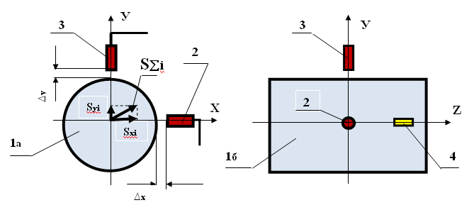
Fig. 6. Scheme of rotor orbit measurement 1a – rotor (end view); 1b – rotor (side view); 2, 3 – non-contact sensors; 4 – reflection mark of phase angle sensor.
In order to make a measurement and build a corresponding graph, it is necessary to carry out a number of preparatory operations, including:
- – install the non-contact linear encoders 2 and 3 in one of the diametrical sections of the rotor at an angle of 90° to each other, provided that the measuring axis of encoder 2 must coincide with the X axis, and the measuring axis of encoder 3 must coincide with the Y axis;
- set the nominal measuring gap ∆x (∆y) between the rotor surface and the sensing element of each linear encoder (for steel ∆ = 3.5 mm);
- – set the phase angle sensor (not shown in the scheme) in the X – Z plane, coinciding with the installation plane of non-contact sensor 2;
- – set a reflective mark 4 on the rotor 1 in the X – Z plane, which is necessary for the phase angle sensor operation;
- – connect non-contact linear encoders 2 and 3 to connectors X1 and X2, and phase angle encoder to connector X3 of the measuring unit;
- өлшеу блогын компьютерге қосу.
Ротор орбитасын өлшеуді бастау үшін негізгі жұмыс терезесінде (1-суретті қараңыз) “F8 – Charts” батырмасын басып, ротордың радиалды дөңгелексіздігінің әртүрлі графиктерін тұрғызуға арналған “Graphs” жұмыс терезесіне өтіңіз (5-суретті қараңыз). Осы жұмыс терезесінде “Orbit” батырмасын басу керек, содан кейін компьютер дисплейінде қажетті өлшем циклі орындалатын жұмыс терезесі пайда болады (7-суретті қараңыз).
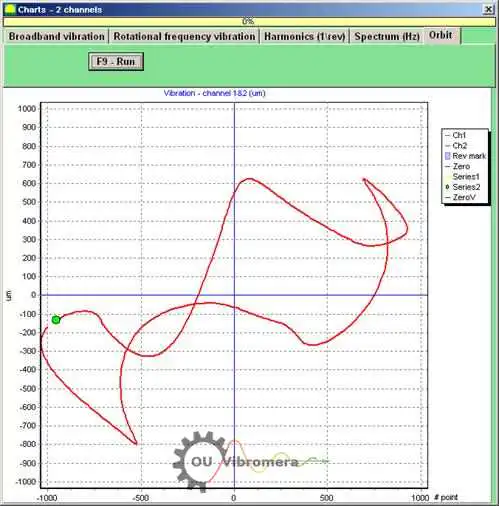
Fig.7. Graph of the rotor orbit. Balanset software.
To continue the work in the specified working window (see Fig. 7) you must turn on the rotor rotation and by pressing the “F9 – RUN” button perform measurement of the instantaneous values of radial run-out of the rotor Sxi and Syi for a period equal to one rotor revolution.
The array of instantaneous values Sxi and Syi obtained during measurement is used to plot the orbit of the controlled rotor (each i-th point of the orbit has the coordinates Sxi, Syi). The instantaneous radial displacement magnitude is calculated by the formula:
S∑i = √ (Sxi² + Syi²) (1)
where S∑i is the instantaneous value of the radial displacement magnitude (the length of the radius vector of the rotor orbit), calculated for the i-th point of the graph;
- Sxi – instantaneous value of the radial run-out of the rotor, measured along the X axis with sensor 2 (see Fig. 6) in the i-th point;
- Syi – instantaneous value of the rotor radial run-out, measured along the Y axis with sensor 3 (see Fig. 6) in the i-th point.

