Upimaji wa mtetemo wa jamaa wa rotor kwa kutumia vipimo vya uhamishaji wa mstari visivyogusa
With the Balancet-1A unaweza kupima ya jamaa vibration of the rota kwa kutumia vipimo vya mstari visivyogusa.
1.1 Uchaguzi wa aina ya kipimo na mipangilio
Kulingana na kazi, vipimo vya mtetemo au vipimo vya uhamishaji vinaweza kutumika kwa upimaji. Ili kuchagua aina ya kipimo, ni lazima kwenye paneli “Aina ya kipimo” (chini ya dirisha kuu) uweke alama kwenye sehemu “Vibro” au “Mstari”.
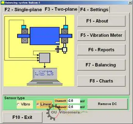
Fig. 1. The main working window of the Balanset program.T
Before starting the measurement it is necessary to make sure that the conversion coefficients of the sensors are set correctly. For this purpose press the button “F4-Settings” in the main working window of the program (see Fig. 1) and go to the settings window designed for entering conversion coefficients (see Fig. 2).
In the working window shown in Fig. 2, in the corresponding fields the conversion coefficients of linear and vibration sensors should be entered. These coefficients are specified in the instrument passport. Usually you do not need to change them.
For the linear displacement vipimo vilivyotumiwa katika seti ya chombo cha Balanset-1A, vigezo vya ubadilishaji ni sawa na:
- Kprl1= 0.94 mV/μm (conversion coefficient of the sensor of the 1st channel);
- Kprl2 = 0.94 mV/μm (conversion coefficient of the sensor of the 2nd channel.
For proper operation, the linear encoder must be installed at a certain distance from the surface of the object of measurement. The nominal clearance between the surface and the end of the sensor is 3.5 mm. In this case there is a constant voltage of 2.48 volts at the sensor output. This voltage will be shown in the fields “Channel1” and “Channel2” for the first and second channels respectively.
To compensate it you must press the button “Remove DC”. A small residual offset will not interfere with the measurement.
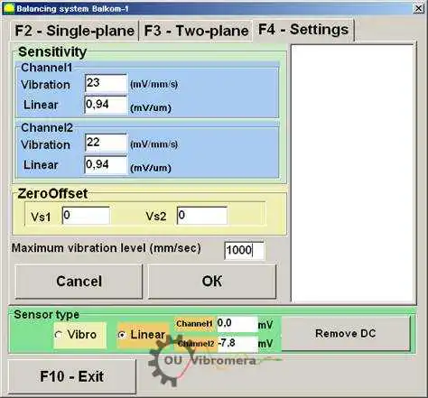
Fig. 2. Working window for entering conversion coefficients and selecting the type of used sensors
Attention! Thamani zilizoainishwa za pengo la kawaida na vigezo vya ubadilishaji vya vipimo vya mstari zimetolewa kwa rotors zilizotengenezwa kwa chuma. Kwa rotors zilizotengenezwa kwa metali nyingine (shaba, bronze, alumini) pengo la kawaida na vigezo vya ubadilishaji vya vipimo vinapaswa kuamuliwa kwa majaribio na mtumiaji kwa kufanya utaratibu wa kalibresheni.
To save the changed parameters press “OK” button. The new parameters will be saved in a file and used for further measurements.
1.2 Kupima runout ya radial ya rotor
Runout ya radial ya rotor inaweza kupimwa kwa vipimo visivyogusa detektor wa kurbanyili katika nyuso mbili za urekebishaji kulingana na mchoro unaoonyeshwa katika Mchoro wa 3. Ili kupima na kupanga kazi ya muda na wigo wa runout ya rotor, ikiwa ni lazima, idadi ya shughuli za maandalizi lazima zifanywe, ikiwemo:
- – select diametrical sections of the rotor, in which the measurements will be carried out;
- kusakinisha vipimo vya uhamishaji wa mstari visivyogusa 5 na 6 na phase kipimo cha pembe 7 kwenye kitanda cha mashine kwa kutumia vifaa maalum (kwa mfano, tripodi za sumaku);
- – connect proximity sensors of linear motion to connectors X1 and X2, and phase angle sensor to connector X3 of the measuring unit;
- – set a nominal measuring gap ∆ between the rotor surface and the sensing element for each linear encoder (for the rotor made of steel ∆ = 3.5 mm);
- – place on the rotor the reflective mark required for triggering for the phase angle sensor 7 and check the sensor triggering;
- unganisha kitengo cha upimaji na kompyuta.
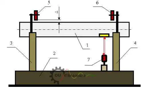
Fig. 3. Measuring the radial run-out of the rotor
If you press the button “F8 – Charts” in the main working window (see Fig. 1), the computer display shows the working window “Graphs” (see Fig. 5), designed to build different kinds of graphs of radial run-out of the rotor.
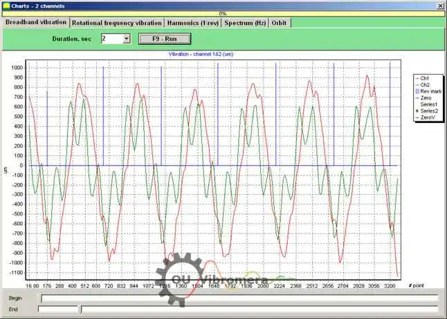
Fig. 5. The working window of the “Charts” mode
Vitufe katika dirisha hili vinajenga grafu zifuatazo:
- When you press the “Broadband vibration” button in this window, the time function of the rotor radial runout is displayed.
- If the “Rotation frequency vibration” button is pressed, the time function of the reciprocal component of the rotor radial runout is displayed.
- If you press the button “Harmonics (1/rev)”, the display will show a decomposition graph of the rotor runout into a harmonic series. The first harmonic corresponds to the value of vibration at the reverse rotor frequency (1x), the second one – at the double frequency (2x), etc.
- By pressing the button “Spectrum (Hz)” the display shows the spectrum of the radial run-out of the rotor.
- By pressing the button “Orbit” the graph of rotor orbit (precession) is displayed.
1.3 Ujenzi wa grafu ya mzunguko wa rotor
Construction of the rotor orbit graph can be performed according to the scheme shown in Fig. 6.
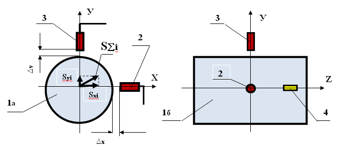
Fig. 6. Scheme of rotor orbit measurement 1a – rotor (end view); 1b – rotor (side view); 2, 3 – non-contact sensors; 4 – reflection mark of phase angle sensor.
In order to make a measurement and build a corresponding graph, it is necessary to carry out a number of preparatory operations, including:
- – install the non-contact linear encoders 2 and 3 in one of the diametrical sections of the rotor at an angle of 90° to each other, provided that the measuring axis of encoder 2 must coincide with the X axis, and the measuring axis of encoder 3 must coincide with the Y axis;
- set the nominal measuring gap ∆x (∆y) between the rotor surface and the sensing element of each linear encoder (for steel ∆ = 3.5 mm);
- – set the phase angle sensor (not shown in the scheme) in the X – Z plane, coinciding with the installation plane of non-contact sensor 2;
- – set a reflective mark 4 on the rotor 1 in the X – Z plane, which is necessary for the phase angle sensor operation;
- – connect non-contact linear encoders 2 and 3 to connectors X1 and X2, and phase angle encoder to connector X3 of the measuring unit;
- unganisha kitengo cha upimaji na kompyuta.
Ili kuanza kupima mzunguko wa rotor katika dirisha kuu la kazi (angalia Mchoro wa 1) bonyeza kitufe “F8 – Chati” na nenda kwenye dirisha la kazi “Grafu” (angalia Mchoro wa 5), ambalo limeundwa kujenga aina mbalimbali za grafu za runout ya radial ya rotor. Katika dirisha hili la kazi lazima ubonyeze kitufe “Mzunguko”, baada ya hapo dirisha la kazi linaonekana kwenye skrini ya kompyuta, ambamo mzunguko muhimu wa upimaji unafanywa (angalia Mchoro wa 7).
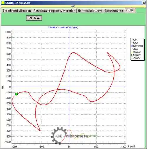
Fig.7. Graph of the rotor orbit. Balanset software.
To continue the work in the specified working window (see Fig. 7) you must turn on the rotor rotation and by pressing the “F9 – RUN” button perform measurement of the instantaneous values of radial run-out of the rotor Sxi and Syi for a period equal to one rotor revolution.
The array of instantaneous values Sxi and Syi obtained during measurement is used to plot the orbit of the controlled rotor (each i-th point of the orbit has the coordinates Sxi, Syi). The instantaneous radial displacement magnitude is calculated by the formula:
S∑i = √ (Sxi² + Syi²) (1)
where S∑i is the instantaneous value of the radial displacement magnitude (the length of the radius vector of the rotor orbit), calculated for the i-th point of the graph;
- Sxi – instantaneous value of the radial run-out of the rotor, measured along the X axis with sensor 2 (see Fig. 6) in the i-th point;
- Syi – instantaneous value of the rotor radial run-out, measured along the Y axis with sensor 3 (see Fig. 6) in the i-th point.

