Objetos não lineares no balanceamento de rotores
Por que o balanceamento “não funciona”, por que os coeficientes de influência mudam e como proceder em condições reais de campo
Visão Geral
Na prática, o balanceamento de rotores quase nunca se resume a simplesmente calcular e instalar uma massa de correção. Formalmente, o algoritmo é bem conhecido e o instrumento executa todos os cálculos automaticamente, mas o resultado final depende muito mais do comportamento do próprio objeto do que do dispositivo de balanceamento. É por isso que, no trabalho real, surgem constantemente situações em que o balanceamento “não funciona”, os coeficientes de influência mudam, a vibração se torna instável e o resultado não é repetível de uma execução para outra.
Vibrações lineares e não lineares, suas características e métodos de balanceamento
O balanceamento bem-sucedido exige compreender como um objeto reage à adição ou remoção de massa. Nesse contexto, os conceitos de objetos lineares e não lineares desempenham um papel fundamental. Compreender se um objeto é linear ou não linear permite a seleção da estratégia de balanceamento correta e ajuda a alcançar o resultado desejado.
Os objetos lineares ocupam um lugar especial nessa área devido à sua previsibilidade e estabilidade. Eles permitem o uso de métodos de diagnóstico e balanceamento simples e confiáveis, tornando seu estudo um passo importante na vibração diagnóstica.
Objetos lineares versus não lineares
A maioria desses problemas tem origem em uma distinção fundamental, mas frequentemente subestimada, entre objetos lineares e não lineares. Um objeto linear, do ponto de vista do balanceamento, é um sistema no qual, a uma velocidade de rotação constante, a amplitude de vibração é proporcional à quantidade de desbalanceamento, e a fase da vibração acompanha a posição angular da massa desbalanceada de forma estritamente previsível. Nessas condições, o coeficiente de influência é um valor constante. Todos os algoritmos padrão de balanceamento dinâmico, incluindo os implementados no Balanset-1A, são projetados precisamente para esses objetos.
Para um objeto linear, o processo de balanceamento é previsível e estável. A instalação de um massa de teste produz uma variação proporcional na amplitude e na fase da vibração. Partidas repetidas geram o mesmo vetor de vibração, e o peso de correção calculado permanece válido. Esses objetos são adequados tanto para balanceamento único quanto para balanceamento em série usando coeficientes de influência armazenados.
Um objeto não linear se comporta de maneira fundamentalmente diferente. A própria base do cálculo de balanceamento é violada. A amplitude de vibração não é mais proporcional ao desbalanceamento, a fase se torna instável e o coeficiente de influência muda dependendo da massa da massa de teste, do modo de operação ou até mesmo do tempo. Na prática, isso se manifesta como um comportamento caótico do vetor de vibração: após a instalação de uma massa de teste, a mudança de vibração pode ser muito pequena, excessiva ou simplesmente não repetível.
O que são objetos lineares?
Um objeto linear é um sistema onde a vibração é diretamente proporcional à magnitude do desbalanceamento.
Um objeto linear, no contexto do balanceamento, é um modelo idealizado caracterizado por uma relação de proporcionalidade direta entre a magnitude do desbalanceamento (massa desbalanceada) e a amplitude de vibração. Isso significa que, se o desbalanceamento for dobrado, a amplitude de vibração também dobrará, desde que a velocidade de rotação do rotor permaneça constante. Por outro lado, reduzir o desbalanceamento diminuirá proporcionalmente as vibrações.
Diferentemente dos sistemas não lineares, onde o comportamento de um objeto pode variar dependendo de muitos fatores, os objetos lineares permitem um alto nível de precisão com esforço mínimo.
Além disso, eles servem como base para o treinamento e prática de balanceadores. Compreender os princípios dos objetos lineares ajuda a desenvolver habilidades que podem ser aplicadas posteriormente a sistemas mais complexos.
Representação gráfica da linearidade
Imagine um gráfico onde o eixo horizontal representa a magnitude da massa desbalanceada (desbalanceamento) e o eixo vertical representa a amplitude de vibração. Para um objeto linear, este gráfico será uma linha reta passando pela origem (o ponto onde tanto a magnitude do desbalanceamento quanto a amplitude de vibração são zero). A inclinação desta linha caracteriza a sensibilidade do objeto ao desbalanceamento: quanto mais íngreme a inclinação, maiores as vibrações para o mesmo desbalanceamento.
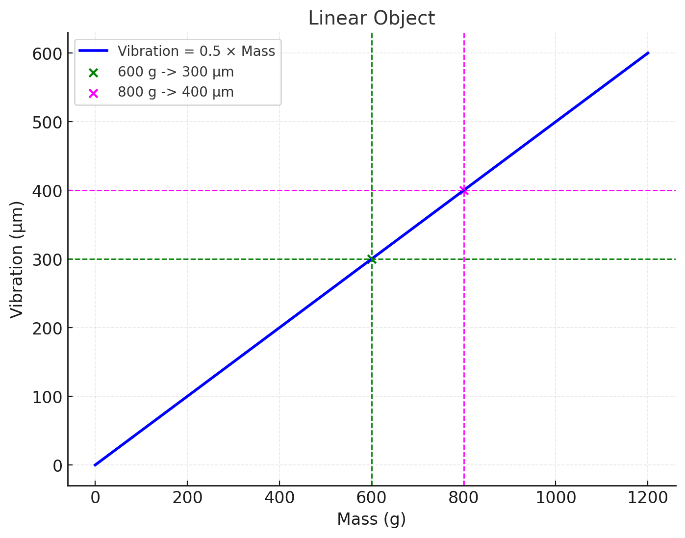
Gráfico 1: A Relação Entre a Amplitude de Vibração (µm) e a Massa Desbalanceada (g) em um raio de correção constante e velocidade de rotação constante
O Gráfico 1 ilustra a relação entre a amplitude de vibração (µm) de um objeto de balanceamento linear e a massa desbalanceada (g) do rotor. O coeficiente de proporcionalidade é 0,5 µm/g. Basta dividir 300 por 600 para obter 0,5 µm/g. Para uma massa desbalanceada de 800 g (MD=800 g), a vibração será 800 g * 0,5 µm/g = 400 µm. Observe que isso se aplica a uma velocidade constante do rotor. Em uma velocidade de rotação diferente, o coeficiente será diferente.
Esse coeficiente de proporcionalidade é chamado de coeficiente de influência (coeficiente de sensibilidade) e tem uma dimensão de µm/g ou, em casos envolvendo desbalanceamento, µm/(g*mm), onde (g*mm) é a unidade de desbalanceamento. Conhecendo o coeficiente de influência (CI), também é possível resolver o problema inverso, ou seja, determinar a massa desbalanceada (MD) com base na magnitude da vibração. Para isso, divida a amplitude de vibração pelo CI.
Por exemplo, se a vibração medida for 300 µm e o coeficiente conhecido for CI=0,5 µm/g, divida 300 por 0,5 para obter 600 g (MD=600 g).
Uma nota sobre unidades: os valores de deslocamento em µm usados nestes exemplos são ilustrativos e escolhidos para facilitar a aritmética. O Balanset-1A mede e exibe a velocidade de vibração, mm/s RMS; o princípio de linearidade e o método do coeficiente de influência funcionam de forma idêntica em qualquer uma das unidades.
Coeficiente de influência (IC): parâmetro-chave de objetos lineares
Uma característica crítica de um objeto linear é o coeficiente de influência (IC). É numericamente igual à tangente do ângulo de inclinação da reta no gráfico de vibração versus desbalanceamento e indica o quanto a amplitude da vibração (em mícrons, µm) muda quando uma unidade de massa (em gramas, g) é adicionada em um plano de correção específico, em uma velocidade específica do rotor. Em outras palavras, o IC é uma medida da sensibilidade do objeto ao desbalanceamento. Sua unidade de medida é µm/g, ou, quando o desbalanceamento é expresso como o produto da massa pelo raio, µm/(g*mm).
O CI é essencialmente a característica “passaporte” de um objeto linear, permitindo previsões de seu comportamento quando massa é adicionada ou removida. Conhecer o CI permite resolver tanto o problema direto – determinar a magnitude da vibração para um desbalanceamento dado – quanto o problema inverso – calcular a magnitude do desbalanceamento a partir da vibração medida.
Problema direto:
Problema inverso:
Como o IC é obtido na prática:
Aqui V0 é o vetor de vibração medido na execução inicial (Run 0), V1 é o vetor medido após uma massa de teste mtrial é instalada (Run 1), K é o coeficiente de influência, e mcorr é a massa de correção. Todas essas são grandezas complexas (vetoriais) combinando amplitude e fase — motivo exato pelo qual o artigo fala abaixo sobre o argumento do coeficiente de influência.
Ao longo deste artigo, a massa em gramas é usada como um substituto para o desbalanceamento: ela é equivalente ao desbalanceamento em g·mm somente enquanto o raio de correção permanecer o mesmo. Quando o raio muda, use g·mm e um IC em µm/(g·mm).
Fase de vibração em objetos lineares
Além da amplitude, a vibração também é caracterizada por sua fase, que indica a posição do rotor no momento do desvio máximo de sua posição de equilíbrio. Para um objeto linear, a fase de vibração também é previsível. É a soma de dois ângulos:
- O ângulo que determina a posição da massa desbalanceada total do rotor. Este ângulo indica a direção na qual o desbalanceamento primário está concentrado.
- O argumento do coeficiente de influência. Este é um ângulo constante que caracteriza as propriedades dinâmicas do objeto e não depende da magnitude ou do ângulo de instalação da massa desbalanceada.
Assim, conhecendo o argumento do CI e medindo a fase de vibração, é possível determinar o ângulo de instalação da massa desbalanceada. Isso permite não apenas o cálculo da magnitude da massa corretiva, mas também sua colocação precisa no rotor para alcançar o balanceamento ótimo.
Balanceamento de objetos lineares
É importante observar que, para um objeto linear, o coeficiente de influência obtido no ensaio de teste como K = (V1 − V0) / mtrial não depende da magnitude ou do ângulo de instalação da massa de teste, nem da vibração inicial. Essa é uma característica fundamental da linearidade. Se o IC permanecer inalterado quando os parâmetros da massa de teste ou a vibração inicial forem alterados, pode-se afirmar com confiança que o objeto se comporta de forma linear dentro da faixa de desbalanceamentos considerada.
Etapas para balancear um objeto linear
- Medição da Vibração Inicial: O primeiro passo é medir a vibração em seu estado inicial. A amplitude e o ângulo de vibração, que indicam a direção do desbalanceamento, são determinados.
- Instalação de uma Massa de Teste: Uma massa de peso conhecido é instalada no rotor. Isso ajuda a compreender como o objeto reage a cargas adicionais e permite que os parâmetros de vibração sejam calculados.
- Remedição da Vibração: Após instalar a massa de teste, novos parâmetros de vibração são medidos. Ao compará-los com os valores iniciais, é possível determinar como a massa afeta o sistema.
- Cálculo da Massa Corretiva: Com base nos dados de medição, a massa e o ângulo de instalação da massa de correção são determinados. Essa massa é colocada no rotor para eliminar o desbalanceamento.
- Verificação Final: Após instalar a massa de correção, a vibração deve ser significativamente reduzida. Se a vibração residual ainda exceder o nível aceitável, o procedimento pode ser repetido.
Nota: Objetos lineares servem como modelos ideais para o estudo e a aplicação prática de métodos de balanceamento. Suas propriedades permitem que engenheiros e diagnosticadores se concentrem no desenvolvimento de habilidades básicas e na compreensão dos princípios fundamentais do trabalho com sistemas de rotores. Embora o objeto perfeitamente linear seja uma idealização, a maioria das máquinas em boas condições mecânicas se comporta de forma suficientemente linear dentro da faixa de desbalanceamento encontrada no balanceamento em campo — e é exatamente por isso que o método do coeficiente de influência funciona. O modelo linear, portanto, não é um exercício acadêmico, mas sim a premissa de trabalho normal; a não linearidade é a exceção que precisa ser reconhecida.







Balanceamento em série e coeficientes armazenados
O balanceamento em série merece atenção especial. Ele pode aumentar significativamente a produtividade, mas somente quando aplicado a objetos lineares e estáveis quanto à vibração. Nesses casos, os coeficientes de influência obtidos no primeiro rotor podem ser reutilizados nos rotores idênticos seguintes. O software do Balanset-1A oferece suporte direto a isso: os coeficientes de uma sessão de balanceamento anterior ficam armazenados no arquivo e podem ser reaplicados a um rotor idêntico com a função Apply coefficients (F8 Reports, arquivo de balanceamento). No entanto, assim que a rigidez dos apoios, a rotação ou a condição dos rolamentos mudam, a repetibilidade se perde e a abordagem em série deixa de funcionar.
Objetos não lineares: quando a teoria diverge da prática
O que é um objeto não linear?
Um objeto não linear é um sistema onde a amplitude de vibração não é proporcional à magnitude do desbalanceamento. Diferentemente dos objetos lineares, onde a relação entre vibração e massa de desbalanceamento é representada por uma linha reta, em sistemas não lineares essa relação pode seguir trajetórias complexas.
No mundo real, nem todos os objetos se comportam de forma linear. Objetos não lineares apresentam uma relação entre desbalanceamento e vibração que não é diretamente proporcional. Isso significa que o coeficiente de influência não é constante e pode variar dependendo de fatores como:
- Magnitude do Desbalanceamento: O aumento do desbalanceamento pode alterar a rigidez dos apoios do rotor, levando a mudanças não lineares na vibração.
- Presença de Folgas e Espaços: Folgas e jogos em rolamentos e outras conexões podem causar mudanças abruptas na vibração sob certas condições.
Mudanças de temperatura e cargas externas variáveis também alteram as características dinâmicas do objeto, mas de uma forma diferente: elas tornam o sistema não estacionário em vez de não linear (veja a seção sobre instabilidade de vibração abaixo).
Por que os objetos não lineares são desafiadores?
A não linearidade introduz muitas variáveis no processo de balanceamento. O trabalho bem-sucedido com objetos não lineares requer mais medições e análises mais complexas. Por exemplo, os métodos padrão aplicáveis a objetos lineares nem sempre produzem resultados precisos para sistemas não lineares. Isso exige uma compreensão mais profunda da física do processo e o uso de métodos de diagnóstico especializados.
Sinais de não linearidade
Um objeto não linear pode ser identificado pelos seguintes sinais:
- Mudanças de vibração não proporcionais: À medida que o desbalanceamento aumenta, a vibração pode crescer mais rápido ou mais devagar do que o esperado para um objeto linear.
- Deslocamento de fase na vibração: A fase da vibração pode mudar de forma imprevisível com variações no desbalanceamento ou na velocidade de rotação.
- Presença de harmônicos e subharmônicos: O espectro de vibração pode exibir harmônicos superiores (múltiplos da frequência de rotação) e subharmônicos (frações da frequência de rotação), indicando efeitos não lineares. No software do Balanset-1A, eles podem ser inspecionados na tela F7 - Charts, aba F5-Spectrum (Hz).
- Histerese: A amplitude da vibração pode depender não apenas do valor atual do desbalanceamento, mas também de seu histórico. Por exemplo, quando o desbalanceamento é aumentado e depois diminuído de volta ao seu valor inicial, a amplitude da vibração pode não retornar ao seu nível original.
Como testar um objeto quanto à linearidade
- Verificação de repetibilidade: Execute o Run 0, pare a máquina, reinicie-a e repita o Run 0 sem tocar em nada. Se a amplitude concordar dentro de cerca de 10% e a fase dentro de cerca de 10–15°, o objeto é estável o suficiente para balancear.
- Verificação de remoção: Após o ensaio de teste, remova o peso de teste e repita o Run 0. Se o vetor de vibração não retornar ao seu valor original, o objeto tem histerese ou folga.
- Verificação de massa dupla: Repita o ensaio de teste com um peso de teste duas vezes mais pesado no mesmo local. Para um objeto linear, a variação do vetor (V1 − V0) deve dobrar em magnitude e manter a mesma direção. Qualquer outro resultado significa que o coeficiente de influência depende da massa de teste — o objeto é não linear.
- Verificação de 180°: O mesmo peso de teste movido 180° deve girar a variação do vetor em 180°.
Representação gráfica da não linearidade
Em um gráfico de vibração versus desbalanceamento, a não linearidade é evidente nos desvios de uma linha reta. O gráfico pode apresentar curvas, curvaturas, laços de histerese e outras características que indicam uma relação complexa entre desbalanceamento e vibração.
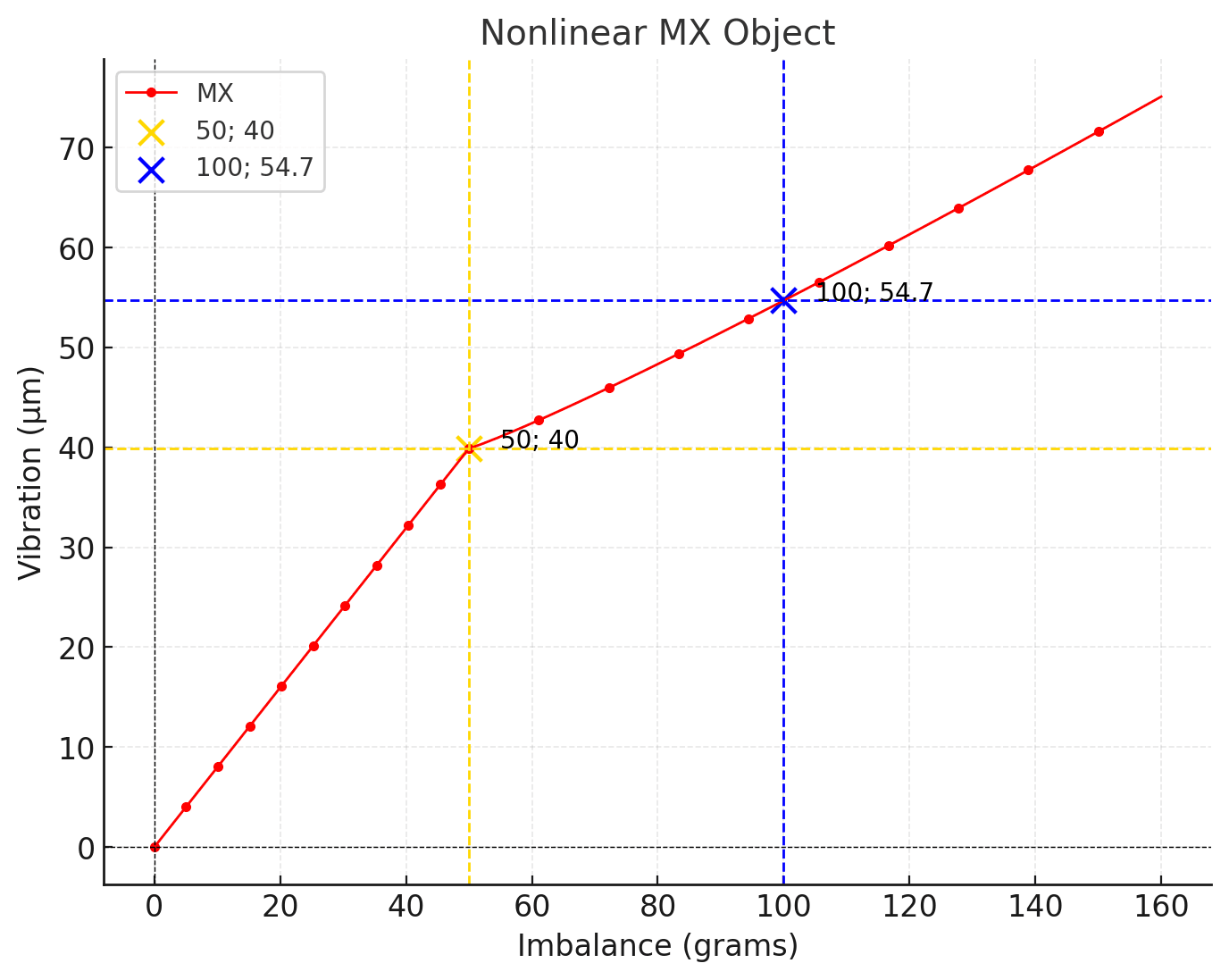
Gráfico 2. Objeto não linear (a raio de correção constante e velocidade de rotação constante)
50 g; 40 µm (amarelo), 100 g; 54,7 µm (azul).
Este objeto apresenta dois segmentos, duas linhas retas. Para desbalanceamentos menores que 50 gramas, o gráfico reflete as propriedades de um objeto linear, mantendo a proporcionalidade entre o desbalanceamento em gramas e a amplitude de vibração em microns. Para desbalanceamentos maiores que 50 gramas, o crescimento da amplitude de vibração desacelera.
Exemplos de objetos não lineares
Exemplos de objetos não lineares no contexto do balanceamento incluem:
- Rotores com trincas: Trincas no rotor podem levar a mudanças não lineares na rigidez e, como resultado, a uma relação não linear entre vibração e desbalanceamento.
- Rotores com folgas nos rolamentos: Folgas nos rolamentos podem causar mudanças abruptas na vibração sob certas condições.
- Rotores com elementos elásticos não lineares: Alguns elementos elásticos, como amortecedores de borracha, podem apresentar características não lineares, afetando a dinâmica do rotor.
Tipos de não linearidade
1. Não linearidade suave-rígida
Nesses sistemas, observam-se dois segmentos: macio e rígido. No segmento macio, o comportamento assemelha-se à linearidade, onde a amplitude da vibração aumenta proporcionalmente à massa de desbalanceamento. No entanto, após um certo limite (ponto de quebra), o sistema transita para um modo rígido, onde o crescimento da amplitude desacelera.
2. Não linearidade elástica
Mudanças na rigidez dos apoios ou contatos dentro do sistema tornam a relação vibração-desbalanceamento complexa. Por exemplo, a vibração pode aumentar ou diminuir subitamente ao cruzar limiares específicos de carga.
3. Não linearidade induzida por atrito
Em sistemas com atrito significativo (por exemplo, em rolamentos), a amplitude da vibração pode ser imprevisível. O atrito pode reduzir a vibração em uma faixa de velocidade e amplificá-la em outra.
Causas comuns de não linearidade
As causas mais comuns de não linearidade são o aumento das folgas dos mancais, o desgaste dos mancais, o atrito seco, os suportes soltos e trincas na estrutura. A operação próxima a uma ressonância é um problema separado: não torna o objeto não linear, mas destrói a repetibilidade da medição e, por isso, é igualmente fatal para o método do coeficiente de influência. Frequentemente, o objeto apresenta a chamada não linearidade macia-dura (soft–hard). Em níveis pequenos de desbalanceamento, o sistema se comporta de forma quase linear, mas, à medida que a vibração aumenta, elementos mais rígidos dos apoios ou da carcaça entram em ação. Nesses casos, o balanceamento só é possível dentro de uma faixa de operação estreita e não fornece resultados estáveis a longo prazo.
Instabilidade de vibração
Outro problema sério é a instabilidade da vibração. Mesmo um objeto formalmente linear pode apresentar mudanças de amplitude e fase ao longo do tempo. Isso é causado por efeitos térmicos, mudanças na viscosidade do lubrificante, dilatação térmica, atrito instável nos apoios e cargas externas variáveis atuando sobre a máquina. Como resultado, medições feitas com apenas alguns minutos de diferença podem produzir vetores de vibração diferentes. Nessas condições, a comparação significativa das medições se torna impossível, e o cálculo de balanceamento perde confiabilidade.
Observe a distinção: um não linear objeto fornece um coeficiente de influência diferente para uma massa de peso de teste diferente; um não estacionário (instável) fornece um coeficiente de influência diferente para o mesmo peso de teste medido em um momento diferente. Ambos comprometem o cálculo, mas os remédios diferem — a não linearidade é corrigida mecanicamente, a instabilidade é corrigida estabilizando o regime de operação e medindo rapidamente.
Balanceamento próximo à ressonância
Balancear perto da ressonância é especialmente problemático. Quando a frequência de rotação está próxima de uma frequência natural do sistema, mesmo um pequeno desbalanceamento produz um aumento acentuado na vibração, e tanto a amplitude quanto a fase tornam-se extremamente sensíveis a pequenas variações de velocidade. Observe que a própria ressonância não é não linearidade: um sistema linear tem ressonâncias, e na ressonância a vibração ainda é proporcional ao desbalanceamento. O que se perde é a repetibilidade — uma dispersão de ±1% na velocidade de rotação perto da velocidade crítica altera o vetor medido muito mais do que o peso de teste, de modo que o coeficiente de influência medido nessa zona é inutilizável na prática. (Uma resposta ressonante grande pode, além disso, levar os apoios a uma faixa genuinamente não linear — mas isso é uma consequência, não a definição.) Nesses casos, a velocidade de balanceamento deve ser afastada da frequência natural, ou a estrutura mecânica deve ser alterada, antes de tentar o balanceamento.
Alta vibração após balanceamento “bem-sucedido”
Na prática, é comum encontrar situações em que, após um procedimento de balanceamento formalmente bem-sucedido, o nível geral de vibração permanece alto. Isso não indica um erro do instrumento ou do operador. O balanceamento elimina apenas o desbalanceamento de massa. Se a vibração for causada por defeitos na fundação, elementos de fixação frouxos, desalinhamento ou ressonância, as massas de correção não resolverão o problema. Nesses casos, analisar a distribuição espacial da vibração na máquina e em sua fundação ajuda a identificar a causa real.
Balanceamento de objetos não lineares: uma tarefa complexa com soluções não convencionais
O balanceamento de objetos não lineares é uma tarefa desafiadora que requer métodos e abordagens especializados. O método padrão de massa de teste, desenvolvido para objetos lineares, pode produzir resultados errôneos ou ser totalmente inaplicável.
Métodos de balanceamento para objetos não lineares
- Balanceamento passo a passo: Este método envolve a redução gradual do desbalanceamento pela instalação de massas de correção em cada etapa. Após cada etapa, são realizadas medições de vibração e uma nova massa de correção é determinada com base no estado atual do objeto. Esta abordagem leva em conta as mudanças no coeficiente de influência durante o processo de balanceamento.
- Balanceamento em várias velocidades: Os coeficientes de influência dependem da rotação, de modo que um rotor que precisa operar em uma ampla faixa de rotações pode exigir coeficientes medidos em mais de uma rotação. Este é o domínio do balanceamento modal (multivelocidade) de rotores flexíveis e exige um objeto linear e repetível, vários planos de correção e, como regra, uma máquina de balanceamento. Não é uma solução alternativa para um objeto não linear, e não significa balancear perto de uma ressonância — as rotações de medição ainda devem ser escolhidas longe das velocidades críticas. No procedimento de coeficientes de influência do Balanset-1A, todas as corridas (Run 0 / Run 1 / Run 2 / Run T) devem ser realizadas na mesma rotação.
- Uso de modelos matemáticos: Para objetos não lineares complexos, podem ser empregados modelos matemáticos que descrevem a dinâmica do rotor, levando em conta os efeitos não lineares. Esses modelos ajudam a prever o comportamento do objeto sob várias condições e a determinar os parâmetros de balanceamento ideais.
A experiência e a intuição de um especialista desempenham um papel crucial no balanceamento de objetos não lineares. Um balanceador experiente pode reconhecer sinais de não linearidade, selecionar um método apropriado e adaptá-lo à situação específica. Analisar os espectros de vibração, observar as mudanças de vibração à medida que os parâmetros operacionais do objeto variam e considerar as características de projeto do rotor auxiliam na tomada de decisões corretas e na obtenção dos resultados desejados.
Como balancear objetos não lineares usando uma ferramenta projetada para objetos lineares
Esta é uma boa pergunta. Meu método pessoal para balancear tais objetos começa com a reparação do mecanismo: substituição de rolamentos, soldagem de trincas, aperto de parafusos, verificação de âncoras ou isoladores de vibração e confirmação de que o rotor não atrita contra elementos estruturais estacionários.
Em seguida, identifico as frequências de ressonância, já que é impossível balancear um rotor em velocidades próximas da ressonância. Para isso, uso o método de impacto para determinação da ressonância (a função Bump Test do software Balanset-1A) ou um gráfico de parada por inércia (coast-down) do rotor (a função RunDown).
Em seguida, determino a posição do sensor no mecanismo: vertical, horizontal ou em ângulo.
Após as rodadas de teste, o dispositivo indica o ângulo e o peso das cargas de correção. Reduzo pela metade o peso da carga de correção, mas utilizo os ângulos sugeridos pelo dispositivo para a colocação no rotor. Se a vibração residual após a correção ainda ultrapassar o nível admissível, realizo outra rodada do rotor. Naturalmente, isso leva mais tempo, mas os resultados às vezes são inspiradores.
A arte e a ciência do balanceamento de equipamentos rotativos
O balanceamento de equipamentos rotativos é um processo complexo que combina elementos de ciência e arte. Para objetos lineares, o balanceamento envolve cálculos relativamente simples e métodos padrão. No entanto, o trabalho com objetos não lineares exige um profundo entendimento da dinâmica de rotores, a capacidade de analisar sinais de vibração e a habilidade de escolher as estratégias de balanceamento mais eficazes.
Experiência, intuição e melhoria contínua das habilidades são o que fazem de um balanceador um verdadeiro mestre de sua arte. Afinal, a qualidade do balanceamento não apenas determina a eficiência e a confiabilidade da operação do equipamento, mas também garante a segurança das pessoas.
Repetibilidade de medição
Problemas de medição também desempenham um papel importante. A instalação incorreta de sensores de vibração, mudanças nos pontos de medição ou orientação inadequada do sensor afetam diretamente tanto a amplitude quanto a fase. Para o balanceamento, não basta medir a vibração; a repetibilidade e a estabilidade das medições são críticas. É por isso que, no trabalho prático, os locais de montagem e as orientações dos sensores devem ser rigorosamente controlados.
Abordagem prática para objetos não lineares
O balanceamento de um objeto não linear sempre começa não pela instalação de uma massa de teste, mas pela avaliação do comportamento da vibração. Se a amplitude e a fase claramente derivam ao longo do tempo, mudam de uma partida para outra ou reagem bruscamente a pequenas variações de velocidade, a primeira tarefa é alcançar o modo operacional mais estável possível. Sem isso, qualquer cálculo será aleatório.
O primeiro passo prático é escolher a velocidade correta. Objetos não lineares são extremamente sensíveis à ressonância, portanto, o balanceamento deve ser realizado em uma velocidade o mais distante possível das frequências naturais. Isso frequentemente significa operar abaixo ou acima da faixa operacional usual. Mesmo que a vibração nessa velocidade seja maior, mas estável, é preferível ao balanceamento em uma zona de ressonância.
Em seguida, é importante minimizar todas as fontes de não linearidade adicional. Antes do balanceamento, todos os elementos de fixação devem ser verificados e apertados, as folgas eliminadas na medida do possível e os apoios e conjuntos de rolamentos inspecionados quanto a folgas mecânicas. O balanceamento não compensa folgas ou atrito, mas pode ser possível se esses fatores forem levados a uma condição estável.
Ao trabalhar com um objeto não linear, massas de teste pequenas não devem ser usadas por hábito. Uma massa de teste muito pequena frequentemente não consegue mover o sistema para uma região repetível e a mudança de vibração torna-se comparável ao ruído de instabilidade. A massa de teste deve ser grande o suficiente para causar uma mudança clara e reprodutível no vetor de vibração, mas não tão grande a ponto de levar o objeto a um regime operacional diferente.
As medições devem ser realizadas rapidamente e sob condições idênticas. Quanto menos tempo passar entre as medições, maior a chance de que os parâmetros dinâmicos do sistema permaneçam inalterados. É aconselhável realizar várias corridas de controle sem alterar a configuração para confirmar que o objeto se comporta de forma consistente.
É muito importante fixar os pontos de montagem dos sensores de vibração e sua orientação. Para objetos não lineares, mesmo um pequeno deslocamento do sensor pode causar mudanças perceptíveis na fase e na amplitude, que podem ser erroneamente interpretadas como o efeito da massa de teste.
Nos cálculos, a atenção deve ser voltada não para a concordância numérica exata, mas para as tendências. Se a vibração diminui consistentemente com correções sucessivas, isso indica que o balanceamento está seguindo na direção correta, mesmo que os coeficientes de influência não converjam formalmente.
Não é recomendado armazenar e reutilizar coeficientes de influência para objetos não lineares. Mesmo que um ciclo de balanceamento seja bem-sucedido, durante a próxima partida o objeto pode entrar em um regime diferente e os coeficientes anteriores não serão mais válidos.
Deve-se lembrar que o balanceamento de um objeto não linear é frequentemente um compromisso. O objetivo não é alcançar a vibração mais baixa possível, mas levar a máquina a uma condição estável e repetível com um nível de vibração aceitável. Em muitos casos, esta é uma solução temporária até que os rolamentos sejam reparados, os apoios restaurados ou a estrutura modificada.
O princípio prático principal é estabilizar o objeto primeiro, depois balanceá-lo e apenas após isso avaliar o resultado. Se a estabilização não puder ser alcançada, o balanceamento deve ser considerado uma medida auxiliar e não uma solução final.
Técnica de massa de correção reduzida
Na prática, ao balancear objetos não lineares, outra técnica importante frequentemente se mostra eficaz. Se o instrumento calcula uma massa de correção usando um algoritmo padrão, instalar a massa calculada completa frequentemente piora a situação: a vibração pode aumentar, a fase pode saltar e o objeto pode mudar para um modo operacional diferente.
Nesses casos, instalar uma massa de correção reduzida funciona bem — duas ou, às vezes, até três vezes menor que o valor calculado pelo instrumento. Isso ajuda a evitar “jogar” o sistema para fora da região condicionalmente linear para outro regime não linear. Em efeito, a correção é aplicada suavemente, com um pequeno passo, sem causar uma mudança brusca nos parâmetros dinâmicos do objeto.
Após instalar a massa reduzida, uma corrida de controle deve ser realizada e a tendência de vibração avaliada. Se a amplitude diminui consistentemente e a fase permanece relativamente estável, a correção pode ser repetida usando a mesma abordagem, aproximando-se gradualmente do nível de vibração mínimo alcançável. Este método passo a passo é frequentemente mais confiável do que instalar a massa de correção calculada completa de uma vez.
Esta técnica é especialmente eficaz para objetos com folgas, atrito seco e apoios suave–rígidos, onde a correção calculada completa imediatamente leva o sistema para fora da zona condicionalmente linear. O uso de massas de correção reduzidas permite que o objeto permaneça no regime operacional mais estável e torna possível alcançar um resultado prático mesmo onde o balanceamento é formalmente considerado impossível.
É importante entender que isso não é um “erro do instrumento”, mas uma consequência da física dos sistemas não lineares. O instrumento calcula corretamente para um modelo linear, enquanto o engenheiro adapta o resultado na prática ao comportamento real do sistema mecânico.
Princípio final
Em última análise, um balanceamento bem-sucedido não se resume a calcular um peso e um ângulo. Requer a compreensão do comportamento dinâmico do objeto, de sua linearidade, da estabilidade da vibração e da distância em relação às condições de ressonância. O Balanset-1A fornece todas as ferramentas necessárias para medição, análise e cálculo, mas o resultado final é sempre determinado pela condição mecânica do próprio sistema. É isso que distingue uma abordagem formal da prática real de engenharia em diagnóstico de vibração e balanceamento de rotores.
Perguntas & respostas
Isso é um sinal de um objeto não linear. Em um objeto linear, a amplitude da vibração é proporcional à quantidade de desbalanceamento, e a fase muda no mesmo ângulo que a posição angular do peso. Quando essas condições são violadas, o coeficiente de influência deixa de ser constante e o algoritmo padrão de balanceamento começa a produzir erros. As causas típicas são folgas nos mancais, apoios soltos, atrito e operação perto da ressonância — o que não é não linearidade em si, mas amplifica a vibração e destrói a repetibilidade das leituras (verifique com o Bump Test).
Um objeto linear é um sistema de rotor em que, na mesma velocidade de rotação, a amplitude da vibração é diretamente proporcional à magnitude do desbalanceamento e a fase da vibração segue estritamente a posição angular da massa desbalanceada. Para esses objetos, o coeficiente de influência é constante e não depende da massa da massa de teste.
Um objeto não linear é um sistema em que a proporcionalidade entre vibração e desbalanceamento e/ou a constância da relação de fase é violada. A amplitude e a fase da vibração começam a depender da massa da massa de teste. Na maioria das vezes, isso está associado a folgas dos rolamentos, desgaste, atrito seco, suportes macios–duros ou o engajamento de elementos estruturais mais rígidos.
Sim, mas o resultado é instável e depende do modo de operação. O balanceamento é possível apenas dentro de uma faixa limitada onde o objeto se comporta de forma condicionalmente linear. Fora dessa faixa, os coeficientes de influência mudam e a repetibilidade do resultado é perdida.
O coeficiente de influência é uma medida da sensibilidade da vibração a mudanças no desbalanceamento. Ele mostra o quanto o vetor de vibração mudará quando uma massa de teste conhecida for instalada em um determinado plano a uma determinada velocidade.
O coeficiente de influência é instável se o objeto for não linear, se a vibração for instável ao longo do tempo, ou se houver ressonância, aquecimento térmico, elementos de fixação afrouxados ou condições de atrito variáveis. Nesses casos, partidas repetidas produzem valores diferentes de amplitude e fase.
Os coeficientes de influência armazenados podem ser usados apenas para rotores idênticos operando na mesma velocidade, nas mesmas condições de instalação e rigidez de apoio. O objeto deve ser linear e estável em vibração. Mesmo uma leve mudança nas condições torna os coeficientes antigos não confiáveis.
Durante o aquecimento, as folgas dos rolamentos, a rigidez de apoio, a viscosidade do lubrificante e o nível de atrito mudam. Isso altera os parâmetros dinâmicos do sistema e, como resultado, muda a amplitude e a fase da vibração.
Instabilidade de vibração é uma mudança na amplitude e/ou fase ao longo do tempo em uma velocidade de rotação constante. O balanceamento depende da comparação de vetores de vibração, então quando a vibração é instável, a comparação perde o sentido e o cálculo torna-se não confiável.
Existem instabilidade estrutural inerente, instabilidade lenta de “deriva”, variação de uma partida para outra, instabilidade relacionada ao aquecimento e instabilidade relacionada à ressonância ao operar perto das frequências naturais.
Na zona de ressonância, mesmo um pequeno desbalanceamento causa um aumento acentuado na vibração, e tanto a amplitude quanto a fase tornam-se extremamente sensíveis a pequenas variações de velocidade. A própria ressonância não é não linearidade — um sistema linear tem ressonâncias, e na ressonância a vibração ainda é proporcional ao desbalanceamento. O que se perde é a repetibilidade: a dispersão normal na velocidade de rotação perto da velocidade crítica altera o vetor medido muito mais do que o peso de teste, de modo que o coeficiente de influência medido nessa zona é inutilizável na prática. A velocidade de balanceamento deve ser afastada da frequência natural antes de se tentar o balanceamento.
Os sinais típicos são um aumento acentuado da vibração com pequenas mudanças de velocidade, fase instável, picos largos no espectro e alta sensibilidade da vibração a pequenas variações de RPM. Um máximo de vibração é frequentemente observado durante a aceleração ou a desaceleração. O indicador mais confiável é a fase: à medida que a velocidade passa por uma ressonância, o atraso de fase passa por cerca de 90° no pico e inverte em aproximadamente 180° acima dele. Observe a leitura de fase durante uma aceleração ou desaceleração lenta — uma variação de 180° junto com um máximo de amplitude localiza a velocidade crítica.
Alta vibração pode ser causada por ressonância, estruturas afrouxadas, defeitos na fundação ou problemas nos rolamentos. Nesses casos, o balanceamento não eliminará a causa da vibração.
O deslocamento de vibração caracteriza a amplitude do movimento, a velocidade de vibração caracteriza a velocidade desse movimento e a aceleração de vibração caracteriza a aceleração. Essas grandezas estão relacionadas, mas cada uma é mais adequada para detectar certos tipos de defeitos e faixas de frequência.
A velocidade de vibração reflete o nível de energia da vibração em uma ampla faixa de frequência e é conveniente para avaliar a condição geral das máquinas de acordo com normas ISO como ISO 10816-1.
A conversão correta é possível apenas para vibração harmônica de frequência única. Para espectros de vibração complexos, essas conversões fornecem apenas resultados aproximados.
Possíveis razões incluem ressonância, defeitos na fundação, elementos de fixação afrouxados, desgaste dos rolamentos, desalinhamento ou não linearidade do objeto. O balanceamento remove apenas o desbalanceamento, não outros defeitos.
Se defeitos mecânicos não forem detectados e a vibração não diminuir após o balanceamento, é necessário analisar a distribuição da vibração na máquina e na fundação. Sinais típicos são alta vibração da carcaça e da base, e defasagens entre os pontos de medição.
A instalação incorreta do sensor distorce a amplitude e a fase, reduz a repetibilidade da medição e pode levar a conclusões diagnósticas incorretas e resultados de balanceamento errôneos.
A vibração é distribuída de forma desigual em toda a estrutura. Rigidez, massas e formas modais diferem, então a amplitude e a fase podem variar significativamente de ponto para ponto.
Como regra, não. O desgaste e o aumento das folgas tornam o objeto não linear. O balanceamento torna-se instável e não fornece um resultado de longo prazo. Exceções são possíveis apenas com folgas de projeto e condições estáveis.
A partida cria altas cargas dinâmicas. Se a estrutura estiver afrouxada, as posições relativas dos elementos mudam após cada partida, levando a mudanças nos parâmetros de vibração.
O balanceamento em série é possível para rotores idênticos instalados em condições idênticas, com estabilidade de vibração e ausência de ressonância. Nesse caso, os coeficientes de influência do primeiro rotor podem ser aplicados aos subsequentes.
Isso geralmente se deve a mudanças na rigidez de apoio, diferenças de montagem, mudanças na velocidade de rotação ou transição do objeto para um regime de operação não linear.
Redução da vibração para um nível estável mantendo a repetibilidade da amplitude e da fase de uma partida para outra, e a ausência de sinais de ressonância ou não linearidade.

Nikolai Shelkovenko
Nikolai Shelkovenko é engenheiro de análise de vibrações e fundador e diretor executivo da Vibromera. Há mais de 15 anos ele balanceia equipamentos rotativos em campo, e não em uma bancada de testes: trituradores, ventiladores industriais, britadores, centrífugas, eixos e fusos. Foi desse trabalho que nasceram os instrumentos Balanset — eles foram concebidos como uma ferramenta que o especialista pode levar até a máquina e usar sozinho, no local, e não como equipamento de laboratório. A Vibromera foi fundada em 2017 e, desde 2023, está sediada no Porto, em Portugal. É aqui que acontecem o desenvolvimento, a montagem e o suporte da linha Balanset. O instrumento principal é o Balanset-1A, um analisador portátil para balanceamento em um e dois planos e para diagnóstico de vibrações. Nikolai participa pessoalmente do suporte ao cliente, da solução de casos difíceis de balanceamento e do desenvolvimento do software. Ele atende clientes no mundo todo, em qualquer idioma.


0 comentário