موازنة الدوار: عدم التوازن الساكن والديناميكي، والرنين، والإجراءات العملية
يشرح هذا الدليل عملية موازنة الدوار لـ دوارات صلبة: ما معنى "عدم التوازن"، وكيف يختلف عدم التوازن الثابت عن عدم التوازن الديناميكي، ولماذا يمكن أن يمنع الرنين وعدم الخطية الحصول على نتيجة جيدة، وكيف يتم إجراء الموازنة عادةً في مستوى تصحيح واحد أو مستويين.


محتويات
- ما هو الدوار وما الذي يُصححه التوازن؟
- أنواع الدوارات وأنواع عدم التوازن
- اهتزاز الآليات: ما يمكن وما لا يمكن إزالته من خلال الموازنة
- الرنين: عامل يمنع التوازن
- النماذج الخطية مقابل النماذج غير الخطية: متى تتوقف الحسابات عن العمل
- Balancing devices and balancing machines
- موازنة الدوارات الصلبة (ملاحظات عملية)
- كيفية إجراء الموازنة الديناميكية (طريقة التشغيل الثلاثي)
- معايير تقييم جودة الموازنة
- المعايير والمراجع
- FAQ
ما هو الدوار وما الذي يُصححه التوازن؟
The rotor is a body which rotates about some axis and is held by its bearing surfaces in the supports. The bearing surfaces of the rotor transmit loads to the supports via rolling or sliding bearings. The bearing surfaces are the surfaces of the trunnions or the surfaces that replace them.
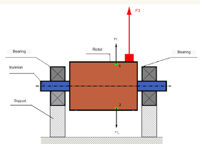
في الدوّار المتوازن تمامًا، تتوزع كتلته بشكل متناظر حول محور الدوران، أي أن أي عنصر من عناصر الدوّار يمكن مطابقته مع عنصر آخر متناظر حول محور الدوران. في الدوّار المتوازن، تتوازن قوة الطرد المركزي المؤثرة على أي عنصر من عناصر الدوّار مع قوة الطرد المركزي المؤثرة على العنصر المتناظر. على سبيل المثال، تؤثر قوتا الطرد المركزي F1 وF2، متساويتان في المقدار ومتعاكستان في الاتجاه، على العنصرين 1 و2 (المُشار إليهما باللون الأخضر في الشكل 1). ينطبق هذا على جميع عناصر الدوّار المتناظرة، وبالتالي فإن إجمالي قوة الطرد المركزي المؤثرة على الدوّار يساوي صفرًا، ويكون الدوّار متوازنًا.
لكن في حال انكسر تناظر الدوّار (يُشار إلى العنصر غير المتناظر باللون الأحمر في الشكل 1)، فإن قوة طرد مركزي غير متوازنة F3 تؤثر على الدوّار. وعند الدوران، يتغير اتجاه هذه القوة بتغير اتجاه الدوّار. وينتقل الحمل الديناميكي الناتج عن هذه القوة إلى المحامل، مما يؤدي إلى تسارع التآكل.
In addition, under the influence of this variable in direction force there is a cyclic deformation of supports and foundation, on which the rotor is fixed, i.e. there is vibration. In order to eliminate rotor imbalance and the accompanying vibration, balancing masses must be installed to restore symmetry to the rotor.
Rotor balancing is an operation to correct imbalance by adding balancing masses.
The task of balancing is to find the size and location (angle) of one or more balancing masses.
أنواع الدوارات وأنواع عدم التوازن
مع الأخذ في الاعتبار قوة مادة الدوار ومقدار قوى الطرد المركزي المؤثرة عليه، يمكن تقسيم الدوارات إلى نوعين - الدوارات الصلبة والدوارات المرنة.
Rigid rotors deform insignificantly under action of centrifugal force at working modes and influence of this deformation in calculations can be neglected.
لم يعد بالإمكان إهمال تشوه الدوارات المرنة. يُعقّد هذا التشوه حلّ مسألة الموازنة، ويتطلب تطبيق نماذج رياضية مختلفة مقارنةً بمسألة موازنة الدوارات الصلبة. تجدر الإشارة إلى أن الدوار نفسه قد يتصرف كجسم صلب عند السرعات المنخفضة، وكجسم مرن عند السرعات العالية. سنقتصر فيما يلي على دراسة موازنة الدوارات الصلبة فقط.
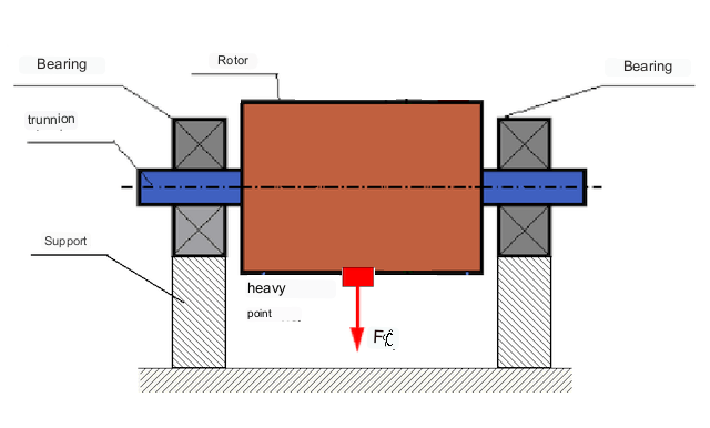
اعتمادًا على توزيع الكتل غير المتوازنة على طول الدوّار، يمكن تمييز نوعين من عدم التوازن: ثابت وديناميكي (لحظي). وبناءً على ذلك، يُشار إلى توازن الدوّار بالتوازن الثابت والديناميكي. يحدث عدم توازن الدوّار الثابت دون دوران الدوّار، أي في حالة السكون، عندما ينعكس اتجاه الدوّار بفعل الجاذبية بحيث تكون "نقطة ثقله" متجهة للأسفل. يوضح الشكل 2 مثالًا على دوّار يعاني من عدم توازن ثابت.
Dynamic unbalance occurs only when the rotor is rotating.
An example of a rotor with dynamic unbalance is shown in Fig. 3.
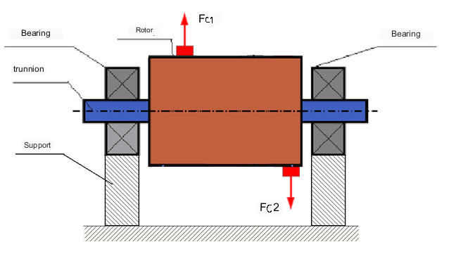
في هذه الحالة، تقع الكتلتان المتساويتان غير المتوازنتين M1 وM2 في مستويين مختلفين - أي في مواقع مختلفة على طول الدوار. في الوضع الساكن، أي عندما لا يدور الدوار، تؤثر عليه قوة الجاذبية فقط، وتتوازن الكتلتان. أما في الوضع الديناميكي، فعندما يدور الدوار، تبدأ قوتان طاردتان مركزيتان Fc1 وFc2 بالتأثير على الكتلتين M1 وM2. هاتان القوتان متساويتان في المقدار ومتعاكستان في الاتجاه. ومع ذلك، ولأنهما تؤثران في مواقع مختلفة على طول العمود وليستا على نفس الخط، فإنهما لا تعوضان بعضهما البعض. تُحدث القوتان Fc1 وFc2 عزم دوران يؤثر على الدوار. لذلك، يُطلق على هذا الاختلال أيضًا اسم عدم توازن العزم. وبناءً على ذلك، تؤثر قوى الطرد المركزي غير المعوضة على مواضع المحامل، والتي قد تتجاوز القيم المحسوبة بشكل كبير، مما يقلل من عمر خدمة المحامل.
بما أن هذا النوع من عدم التوازن يحدث ديناميكيًا فقط أثناء دوران الدوّار، يُسمى عدم التوازن الديناميكي. ولا يمكن تصحيحه في الظروف الساكنة عن طريق الموازنة باستخدام سكاكين أو طرق مشابهة. وللتخلص من عدم التوازن الديناميكي، يجب تركيب وزنين مُعاكسين يُنتجان عزمًا مساويًا في المقدار ومعاكسًا في الاتجاه للعزم الناتج عن الكتلتين M1 وM2. ليس من الضروري أن تكون الكتلتان المُعاكستان مُعاكستين في المقدار ومساويتين في الاتجاه للكتلين M1 وM2، فالمهم هو أن تُنتجا عزمًا يُعوض تمامًا عزم عدم التوازن.
بشكل عام، قد لا تتساوى الكتلتان M1 وM2، مما يؤدي إلى مزيج من عدم التوازن الساكن والديناميكي. وقد ثبت نظريًا أنه بالنسبة للدوار الصلب، يكفي وجود وزنين متباعدين على طول الدوار لإزالة عدم توازنه. يعوض هذان الوزنان كلاً من عزم الدوران الناتج عن عدم التوازن الديناميكي وقوة الطرد المركزي الناتجة عن عدم تناظر الكتلة بالنسبة لمحور الدوار (عدم التوازن الساكن). عادةً ما يكون عدم التوازن الديناميكي سمة مميزة للدوارات الطويلة، مثل الأعمدة، بينما يكون عدم التوازن الساكن سمة مميزة للدوارات الضيقة. مع ذلك، إذا كان الدوار الضيق مائلاً بالنسبة للمحور، أو مشوهًا (على شكل الرقم ثمانية)، فسيكون من الصعب إزالة عدم التوازن الديناميكي (انظر الشكل 4)، لأنه في هذه الحالة يصعب تركيب أوزان تصحيحية تُحدث عزم التعويض اللازم.
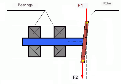
The forces F1 and F2 do not lie on the same line and do not compensate each other.
نظراً لصغر ذراع توليد العزم بسبب ضيق الدوار، قد يلزم استخدام أوزان تصحيح كبيرة. إلا أن هذا يؤدي أيضاً إلى "اختلال توازن مُستحث" نتيجة تشوه الدوار الضيق بفعل قوى الطرد المركزي الناتجة عن أوزان التصحيح. (انظر على سبيل المثال "التعليمات المنهجية لموازنة الدوارات الصلبة (وفقاً للمعيار ISO 22061-76)". القسم 10. نظام دعامات الدوار).
This is noticeable for narrow impellers of fans, in which, in addition to force unbalance, aerodynamic unbalance is also active. And it should be understood that aerodynamic unbalance, or rather aerodynamic force is directly proportional to angular speed of the rotor, and for its compensation the centrifugal force of correcting mass, which is proportional to the square of angular speed, is used. Therefore, the balancing effect can only take place at a specific balancing frequency. At other rotational frequencies there is an additional error.
The same can be said of the electromagnetic forces in an electric motor, which are also proportional to angular velocity. So it is not possible to eliminate all causes of vibration in a machine by balancing.
اهتزاز الآليات
Vibration is the reaction of the mechanism design to the effects of a cyclic excitatory force. This force can be of different nature.
تُعدّ قوة الطرد المركزي الناتجة عن عدم توازن الدوّار قوةً غير مُعوَّضة تؤثر على "النقطة الأثقل". ويمكن التخلص من هذه القوة والاهتزاز الناتج عنها عن طريق موازنة الدوّار.
تنشأ قوى التفاعل ذات الطبيعة "الهندسية" نتيجةً لأخطاء التصنيع والتجميع في الأجزاء المتزاوجة. قد تنشأ هذه القوى، على سبيل المثال، نتيجةً لعدم استدارة أعناق الأعمدة، أو أخطاء في شكل أسنان التروس، أو تموج مجاري المحامل، أو عدم محاذاة الأعمدة المتزاوجة، وما إلى ذلك. في حالة عدم استدارة المحاور، سينزاح محور العمود تبعًا لزاوية دورانه. على الرغم من أن هذا الاهتزاز يحدث أيضًا عند سرعة الدوران، إلا أنه يكاد يكون من المستحيل التخلص منه عن طريق الموازنة.
Aerodynamic forces resulting from the rotation of the impellers of fans and other vane mechanisms. Hydrodynamic forces resulting from the rotation of impellers of hydraulic pumps, turbines, etc.
Electromagnetic forces resulting from the operation of electrical machines, e.g. asymmetric rotor windings, short-circuited windings, etc.
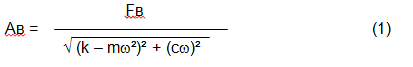
The magnitude of the vibration (e.g. its amplitude Av) depends not only on the excitatory force Fv acting on the mechanism with circular frequency ω, but also on the rigidity k of the mechanism, its mass m , as well as the damping coefficient C.
Various types of sensors can be used to measure vibration and balance mechanisms, including:
- absolute vibration sensors designed to measure vibration acceleration (accelerometers) and vibration velocity sensors;
- أجهزة استشعار الاهتزاز النسبي - التيار الدوامي أو السعوي، مصممة لقياس إزاحة الاهتزاز؛;
- في بعض الحالات (عندما يسمح تصميم الآلية بذلك)، يمكن أيضًا استخدام مستشعرات القوة لتقييم حمل الاهتزاز الخاص بها؛ على وجه الخصوص، يتم استخدامها على نطاق واسع لقياس حمل الاهتزاز لدعامات آلة التوازن ذات المحامل الصلبة.
So, vibration is the reaction of a machine to the action of external forces. The magnitude of vibration depends not only on the magnitude of the force acting on the mechanism, but also on the rigidity of the mechanism design. One and the same force can lead to different vibrations. In a hard-bearing machine, even if the vibration is small, the bearings may be subjected to significant dynamic loads. This is why force rather than vibration sensors (vibration accelerometers) are used when balancing hard-bearing machines.
Vibration sensors are used on mechanisms with relatively pliable supports, when the action of unbalanced centrifugal forces leads to a noticeable deformation of supports and vibration. Force sensors are used for rigid supports, when even significant forces due to unbalance do not lead to significant vibration.
Resonance is a factor that prevents balancing
Earlier we mentioned that rotors are divided into rigid and flexible. Stiffness or flexibility of rotor should not be confused with stiffness or mobility of supports (foundation) on which the rotor is installed. A rotor is considered rigid when its deformation (bending) under the action of centrifugal forces can be neglected. Deformation of flexible rotor is relatively large and cannot be neglected.
In this article, we consider only the balancing of rigid rotors. A rigid (non-deformable) rotor can in turn be mounted on rigid or movable (pliable) supports. It is clear that this stiffness/suspendability of supports is also relative, depending on rotor speed and magnitude of resulting centrifugal forces. A conditional boundary is the frequency of natural vibrations of the rotor supports.
For mechanical systems, the shape and frequency of natural vibrations are determined by the mass and the elasticity of the elements of mechanical system. That is, the frequency of natural vibrations is an internal characteristic of the mechanical system and does not depend on external forces. Being deflected from the state of equilibrium, supports due to elasticity tend to return to the position of equilibrium. But due to the inertia of the massive rotor, this process is in the nature of damped oscillations. These vibrations are the natural vibrations of the rotor-support system. Their frequency depends on the ratio of the mass of the rotor to the elasticity of the supports.
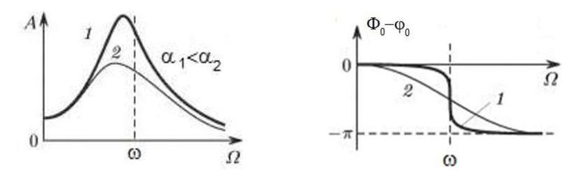
When the rotor begins to rotate and the frequency of its rotation approaches the frequency of natural vibrations, the amplitude of vibration increases sharply, which can lead to the destruction of the structure.
The phenomenon of mechanical resonance occurs. In the area of resonance, a change of rotation speed by 100 rpm may lead to an increase in vibration by tens of times. At the same time (in the resonance area) the vibration phase changes by 180°.
If the design of the mechanism is unsuccessful and the operating frequency of the rotor is close to the frequency of natural vibrations, then the operation of the mechanism becomes impossible because of the inadmissibly high vibration. This is not possible in the usual way, since even a small change in speed will cause a drastic change in the vibration parameters. For balancing in the area of resonance, special methods not considered in this article are used.
It is possible to determine the frequency of natural vibrations of the mechanism at coasting (at switching off the rotor rotation) or by the shock method with the subsequent spectral analysis of the system response to the shock.
For mechanisms, which working frequency of rotation is above the resonance frequency, i.e. working in the resonance regime, the supports are considered to be moving and for measurement are used vibration sensors, mainly vibroacelerometers, measuring acceleration of structural elements. For mechanisms operating in preresonant mode, the supports are considered rigid. In this case, force sensors are used.
Linear and nonlinear models of a mechanical system. Non-linearity is a factor that prevents balancing
When balancing rigid rotors, mathematical models called linear models are used for balancing calculations. A linear model means that in such a model, one quantity is proportional (linear) to the other. For example, if the uncompensated mass on the rotor is doubled, then the vibration value will also be doubled. For rigid rotors, a linear model can be used, since they do not deform.
For flexible rotors, the linear model can no longer be used. For a flexible rotor, if the mass of the heavy point increases during rotation, additional deformation will occur, and in addition to the mass, the radius of the location of the heavy point will also increase. Therefore, for a flexible rotor, the vibration will increase more than twofold, and the usual methods of calculation will not work.
Also, the change of elasticity of supports at their large deformations, for example, when at small deformations of supports some structural elements work, and at large ones other structural elements are involved. This is why you cannot balance mechanisms that are not fixed on a foundation, but, for example, simply placed on the floor. With significant vibrations, the force of the imbalance can pull the mechanism off the floor, thereby significantly changing the stiffness characteristics of the system. Motor feet must be securely fastened, bolt mounts must be tightened, washer thickness must provide sufficient mounting rigidity, etc. If the bearings are broken, significant shaft misalignment and shocks are possible, which will also result in poor linearity and an inability to perform a quality balance.
Balancing devices and balancing machines
كما ذكر أعلاه، فإن الموازنة هي عملية محاذاة المحور المركزي الرئيسي للقصور الذاتي مع محور دوران الدوار.
This process can be performed by two methods.
The first method involves machining the rotor trunnions in such a way that the axis passing through the centers of the trunnions cross section with the main central axis of inertia of the rotor. Such a technique is rarely used in practice and will not be discussed in detail in this article.
The second (most common) method involves moving, installing or removing correction weights on the rotor, which are placed so that the axis of inertia of the rotor is as close to its axis of rotation as possible.
Moving, adding or removing correction weights during balancing may be accomplished by various technological operations including: drilling, milling, surfacing, welding, screwing or unscrewing, laser or electron beam burning, electrolysis, electromagnetic surfacing, etc.
The balancing process can be accomplished in two ways:
- balancing of assembled rotors (in their own bearings) using balancing machines;
- balancing of rotors on balancing machines. For balancing of rotors in their own bearings usually used specialized balancing devices (kits), which allow to measure the vibration of the balanced rotor at its frequency of rotation in vector form, i.e. to measure both the amplitude and the phase of vibration. At present, the above devices are manufactured on the basis of microprocessor technology and (apart from vibration measurement and analysis) provide automatic calculation of parameters of correcting weights, which should be installed on the rotor to compensate its unbalance.
These devices include:
- a measuring and computing unit based on a computer or industrial controller;
- Two (or more) vibration sensors;
- A phase angle sensor;
- accessories for mounting the sensors on the site;
- specialized software, designed to perform a full cycle of rotor vibration parameters measurement in one, two or more correction planes.
Two types of balancing machines are currently the most common:
- Soft-bearings machines (with soft supports);
- Hard-bearings machines (with rigid supports).
تتميز الآلات ذات المحامل المرنة بدعامات مرنة نسبيًا، كالدعامات القائمة على نوابض مسطحة. عادةً ما يكون تردد الاهتزازات الطبيعية لهذه الدعامات أقل بمرتين إلى ثلاث مرات من تردد دوران الدوار الموازن المثبت عليها. تُستخدم عادةً مستشعرات الاهتزاز (مثل مقاييس التسارع ومستشعرات سرعة الاهتزاز) لقياس اهتزاز دعامات ما قبل الرنين في الآلة.
Pre-resonance balancing machines use relatively rigid supports, whose natural frequencies of vibration should be 2-3 times higher than the rotation frequency of the rotor being balanced. Force transducers are usually used to measure the vibration load of the preresonance machine supports.
تتمثل ميزة آلات الموازنة قبل الرنين في إمكانية إجراء الموازنة عليها بسرعات دوران منخفضة نسبيًا (تصل إلى 400 - 500 دورة في الدقيقة)، مما يبسط تصميم الآلة وأساسها بشكل كبير، ويزيد من إنتاجية وسلامة الموازنة.
Balancing rigid rotors
Important!
- Balancing only eliminates vibration caused by asymmetrical distribution of the rotor mass relative to its rotational axis. Other types of vibration are not eliminated by balancing!
- Technical mechanisms, whose design ensures the absence of resonances at the operating frequency of rotation, reliably fixed on the foundation, installed in serviceable bearings, are subject to balancing.
- Defective machinery must be repaired before balancing. Otherwise, quality balancing is not possible.
Balancing is no substitute for repair!
The main task of balancing is to find the mass and location of compensating weights that are subject to balancing centrifugal forces.
As mentioned above, for rigid rotors, it is generally necessary and sufficient to install two compensating weights. This will eliminate both static and dynamic unbalance of the rotor. The general scheme for measuring vibration during balancing is as follows.
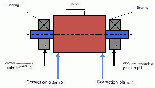
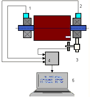
Vibration sensors are installed on the bearing supports at points 1 and 2. A revolution marker is attached to the rotor, usually with reflective tape. The RPM mark is used by the laser tachometer to determine the rotor speed and phase of the vibration signal.
كيفية إجراء الموازنة الديناميكية (طريقة التشغيل الثلاثي)
In most cases dynamic balancing is carried out by the method of three starts. The method is based on the fact that test weights of known weight are placed on the rotor in series in plane 1 and 2 and the weights and the location of the balancing weights are calculated based on the results of changes in the vibration parameters.
The place of installation of weights is called the correction plane. Usually the correction planes are selected in the area of the bearing supports on which the rotor is installed.
At the first start-up the initial vibration is measured. Then a test weight of known weight is placed on the rotor closer to one of the bearings. A second start-up is carried out and the vibration parameters are measured, which should change due to the test weight installation. Then the test weight in the first plane is removed and installed in the second plane. A third test run is performed and the vibration parameters are measured. The test weight is removed and the software automatically calculates the masses and installation angles of the balance weights.
The point of installing the test weights is to determine how the system reacts to changes in imbalance. The weights and locations of the test weights are known, so the software can calculate so called influence coefficients, showing how introducing a known imbalance affects the vibration parameters. The influence coefficients are characteristics of the mechanical system itself and depend on the rigidity of the supports and the mass (inertia) of the rotor-support system.
For the same type of mechanisms of the same design the influence coefficients will be close. It is possible to save them in the computer memory and use them for balancing of the same-type mechanisms without test runs, which significantly increases the productivity of balancing. Note that the mass of test weights should be chosen such that the vibration parameters change noticeably when test weights are installed. Otherwise, the error of calculation of influence coefficients increases and the quality of balancing deteriorates.
As you can see from Fig. 1, the centrifugal force acts in the radial direction, i.e. perpendicular to the rotor axis. Therefore, the vibration sensors must be installed so that their axis of sensitivity also points in the radial direction. Usually, the stiffness of the foundation in the horizontal direction is less, so the vibration in the horizontal direction is higher. Therefore, in order to increase the sensitivity, the sensors should be installed so that their axis of sensitivity is also directed horizontally. Although there is no fundamental difference. In addition to vibration in the radial direction, vibration in the axial direction, along the rotor rotation axis, must be monitored. This vibration is usually not caused by unbalance, but by other causes, mainly related to misalignment and misalignment of the shafts connected through the coupling.
لا يمكن التخلص من هذا الاهتزاز عن طريق الموازنة، وفي هذه الحالة يلزم إجراء محاذاة. عمليًا، عادةً ما تعاني هذه الآلات من عدم توازن في الدوار وعدم محاذاة في العمود، مما يجعل مهمة التخلص من الاهتزاز أكثر صعوبة. في مثل هذه الحالات، من الضروري توسيط الآلة أولًا ثم موازنتها. (مع العلم أنه في حالة عدم توازن عزم الدوران الشديد، يحدث الاهتزاز أيضًا في الاتجاه المحوري نتيجة "التواء" هيكل الأساس).
مقالات ذات صلة (أمثلة على حوامل التوازن)
معايير تقييم جودة آليات الموازنة
The balancing quality of rotors (mechanisms) can be evaluated in two ways. The first method involves comparing the amount of residual unbalance determined during the balancing process with the tolerance for residual unbalance. These tolerances for the different rotor classes are specified in ISO 1940-1-2007. Part 1. Definition of allowable unbalance.
However, compliance with the specified tolerances cannot fully guarantee the operational reliability of the mechanism, associated with the achievement of the minimum level of its vibration. This is explained by the fact that the magnitude of vibration of the mechanism is determined not only by the magnitude of the force associated with the residual unbalance of its rotor, but also depends on several other parameters, including: the rigidity k of the mechanism structural elements, its mass m, the damping factor, as well as the rotation frequency. Therefore, to estimate dynamic qualities of the mechanism (including quality of its balance) in a number of cases it is recommended to estimate the level of residual vibration of the mechanism, which is regulated by a number of standards.
The most common standard, which regulates the admissible levels of vibration of mechanisms is ISO 10816-3-2002. With its help, it is possible to set tolerances for any type of machines, taking into account the power of their electric drive.
In addition to this universal standard, there is a number of specialized standards developed for specific types of machines. For example, 31350-2007 , ISO 7919-1-2002, etc.
المعايير والمراجع
- ISO 1940-1:2007. الاهتزاز. متطلبات جودة توازن الدوارات الصلبة. الجزء 1. تحديد عدم التوازن المسموح به.
- ISO 10816-3:2009. الاهتزاز الميكانيكي - تقييم اهتزاز الآلة عن طريق القياسات على الأجزاء غير الدوارة - الجزء 3: الآلات الصناعية ذات القدرة الاسمية التي تزيد عن 15 كيلوواط والسرعات الاسمية بين 120 دورة في الدقيقة و 15000 دورة في الدقيقة عند قياسها في الموقع.
- ISO 14694:2003. المراوح الصناعية — مواصفات جودة التوازن ومستويات الاهتزاز.
- ISO 7919-1:2002. اهتزاز الآلات بدون حركة ترددية - القياسات على الأعمدة الدوارة ومعايير التقييم - إرشادات عامة.
FAQ
هل يؤدي التوازن إلى إزالة جميع الاهتزازات؟
لا. تعمل عملية الموازنة على إزالة الاهتزازات الناتجة عن التوزيع غير المتماثل لكتلة الدوار بالنسبة لمحور دورانه. أما الاهتزازات الناتجة عن عدم المحاذاة، وعيوب المحامل، والقوى الديناميكية الهوائية/الهيدروديناميكية، والقوى الكهرومغناطيسية، وغيرها من الأسباب، فتتطلب تشخيصات وإجراءات تصحيحية منفصلة.
لماذا قد يفشل التوازن بالقرب من الرنين؟
بالقرب من الرنين، يمكن أن تُحدث تغيرات طفيفة في السرعة تغيرات كبيرة في سعة الاهتزاز وانزياحًا في الطور بمقدار 180 درجة. في مثل هذه الظروف، تصبح نتائج القياس غير مستقرة، وقد لا تتقارب إجراءات الموازنة التقليدية دون استخدام أساليب خاصة.
متى تحتاج إلى موازنة مستوى واحد مقابل موازنة مستويين؟
بالنسبة للدوارات الصلبة، عادةً ما يكون استخدام وزنين متباعدين على طول الدوار ضروريًا وكافيًا للتخلص من عدم التوازن الساكن والديناميكي معًا. أما الدوارات الضيقة، فغالبًا ما تُظهر عدم توازن ساكن في الغالب، ولكن التشوه والهندسة قد يُدخلان عنصرًا ديناميكيًا قد يتطلب تصحيحًا ثنائي المستوى.
ما الذي يجب فعله قبل إجراء عملية الموازنة؟
تأكد من صلاحية الجهاز للاستخدام: تثبيته بإحكام على القاعدة، سلامة المحامل، عدم وجود ارتخاء شديد، وعدم وجود أي مصادر واضحة للانحراف عن الخطية. الموازنة ليست بديلاً عن الإصلاح.
أهم النقاط
- يعمل التوازن على تصحيح الإثارة المتعلقة بالكتلة (الطرد المركزي)؛ فهو لا يحل مشكلة عدم المحاذاة أو تلف المحامل أو المصادر الكهرومغناطيسية/الديناميكية الهوائية.
- يمكن أن يؤدي الرنين وعدم الخطية إلى جعل الموازنة التقليدية غير فعالة أو غير آمنة.
- بالنسبة للدوارات الصلبة، يعتبر التوازن ثنائي المستوى هو الحل العام لعدم التوازن الساكن والديناميكي المدمج.
