Rotor balancing: static and dynamic unbalance, resonance, and practical procedure
This guide explains rotor balancing for rigid rotors: what “unbalance” means, how static and dynamic unbalance differ, why resonance and non-linearity can prevent a quality result, and how balancing is typically performed in one or two correction planes.


Contents
- What is a rotor and what does balancing correct?
- Types of rotors and types of unbalance
- Vibration of mechanisms: what balancing can and cannot remove
- Resonance: a factor that prevents balancing
- Linear vs. nonlinear models: when calculations stop working
- Balancing devices and balancing machines
- Balancing rigid rotors (practical notes)
- How dynamic balancing is performed (three-run method)
- Criteria for assessing balancing quality
- Standards and references
- FAQ
What is a rotor and what does balancing correct?
The rotor is a body which rotates about some axis and is held by its bearing surfaces in the supports. The bearing surfaces of the rotor transmit loads to the supports via rolling or sliding bearings. The bearing surfaces are the surfaces of the trunnions or the surfaces that replace them.
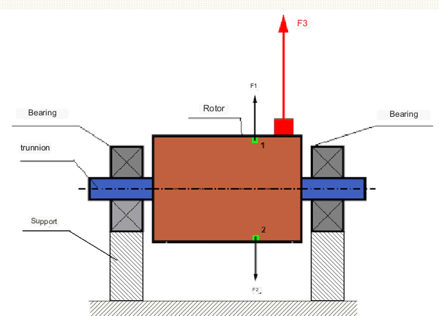
In a perfectly balanced rotor, its mass is distributed symmetrically about the axis of rotation, i.e., any element of the rotor can be matched with another element located symmetrically about the axis of rotation. In a balanced rotor, the centrifugal force acting on any rotor element is balanced by the centrifugal force acting on the symmetrical element. For example, centrifugal forces F1 and F2, equal in magnitude and opposite in direction, act on elements 1 and 2 (marked green in Fig. 1). This is true for all symmetric rotor elements, and thus the total centrifugal force acting on the rotor is 0 and the rotor is balanced.
But if the symmetry of the rotor is broken (asymmetrical element is marked by red color on Fig. 1), then unbalanced centrifugal force F3 acts on the rotor. When rotating, this force changes direction with rotation of the rotor. The dynamic load resulting from this force is transmitted to the bearings, resulting in accelerated wear and tear.
In addition, under the influence of this variable-direction force there is a cyclic deformation of supports and foundation, on which the rotor is fixed, i.e. there is vibration. In order to eliminate rotor imbalance and the accompanying vibration, balancing masses must be installed to restore symmetry to the rotor.
Rotor balancing is an operation to correct imbalance by adding balancing masses.
The task of balancing is to find the size and location (angle) of one or more balancing masses.
Types of rotors and types of unbalance
Taking into account strength of rotor material and magnitude of centrifugal forces acting on it, rotors can be divided into two kinds - rigid rotors and flexible ones.
Rigid rotors deform insignificantly under action of centrifugal force at working modes and influence of this deformation in calculations can be neglected.
Deformation of flexible rotors can no longer be neglected. Deformation of flexible rotors complicates the solution of balancing problem and requires application of other mathematical models in comparison with the problem of balancing of rigid rotors.It should be noted that the same rotor at low speeds can behave as rigid, and at high speeds - as flexible. In the following, we will consider only the balancing of rigid rotors.
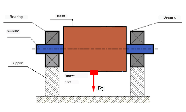
Depending on the distribution of unbalanced masses along the rotor length, two types of unbalance can be distinguished - static and dynamic (momentary). Accordingly, static and dynamic rotor balancing are referred to. Static rotor unbalance occurs without rotation of the rotor, i.e. in statics, when the rotor is reversed by gravity with its "heavy point" downwards. An example of a rotor with static unbalance is shown in Fig. 2
Dynamic unbalance occurs only when the rotor is rotating.
An example of a rotor with dynamic unbalance is shown in Fig. 3.
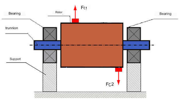
In this case, the unbalanced equal masses M1 and M2 are in different planes - in different places along the length of the rotor. In static position, i.e. when the rotor does not rotate, only gravity acts on the rotor and the masses balance each other. In dynamics, when the rotor rotates, centrifugal forces Fc1 and Fc2 start acting on the masses M1 and M2. These forces are equal in magnitude and opposite in direction. However, since they are applied at different places along the length of the shaft and are not on the same line, these forces do not compensate each other. The forces Fc1 and Fc2 create a torque applied to the rotor. Therefore, this unbalance is also called moment unbalance. Accordingly, uncompensated centrifugal forces act on the bearing positions, which can greatly exceed the calculated values and reduce the service life of the bearings.
Since this type of unbalance occurs only dynamically during the rotation of the rotor, it is called dynamic unbalance. It cannot be corrected in static conditions by balancing "on knives" or similar methods. In order to eliminate dynamic unbalance, two compensating weights must be installed, which produce a moment equal in magnitude and opposite in direction to the moment arising from the masses M1 and M2. The compensating masses do not have to be set opposite and equal in magnitude to the masses M1 and M2. The main thing is that they produce a moment that fully compensates for the unbalance moment.
In general, the masses M1 and M2 may not be equal to each other, so there will be a combination of static and dynamic unbalance. It is theoretically proven that for a rigid rotor, two weights spaced apart along the length of the rotor are necessary and sufficient to eliminate its imbalance. These weights will compensate both the torque resulting from dynamic unbalance and the centrifugal force resulting from the asymmetry of the mass relative to the rotor axis (static unbalance). Typically, dynamic unbalance is characteristic of long rotors, such as shafts, and static unbalance is characteristic of narrow rotors. However, if the narrow rotor is skewed relative to the axis, or deformed ("figure eight"), then dynamic unbalance will be difficult to eliminate. (see Fig. 4), because in this case it is difficult to install correcting weights that create the necessary compensating moment.
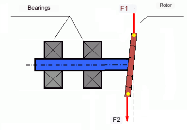
The forces F1 and F2 do not lie on the same line and do not compensate each other.
Due to the fact that the arm to create torque is small due to the narrow rotor, large correction weights may be required. However, this also results in an "induced imbalance" due to the deformation of the narrow rotor by centrifugal forces from the correction weights. (See for example "Methodological instructions for balancing rigid rotors (to GOST 22061-76; its modern international counterpart is ISO 21940-11, formerly ISO 1940-1)". Section 10. ROTOR-SUPPORTS SYSTEM. )
This is noticeable for narrow impellers of fans, in which, in addition to force unbalance, aerodynamic unbalance is also active. And it should be understood that aerodynamic unbalance, or rather aerodynamic force is directly proportional to angular speed of the rotor, and for its compensation the centrifugal force of correcting mass, which is proportional to the square of angular speed, is used. Therefore, the balancing effect can only take place at a specific balancing frequency. At other rotational frequencies there is an additional error.
The same can be said of the electromagnetic forces in an electric motor, which are also proportional to angular velocity. So it is not possible to eliminate all causes of vibration in a machine by balancing.
Vibration of mechanisms
Vibration is the reaction of the mechanism design to the effects of a cyclic excitatory force. This force can be of different nature.
The centrifugal force resulting from the unbalanced rotor is an uncompensated force acting on the "heavy point". It is this force and the vibration caused by it that can be eliminated by balancing the rotor.
Interaction forces of a "geometrical" nature arising from manufacturing and assembly errors of the mating parts. These forces can, for example, arise as a result of non-roundness of shaft necks, errors in the profiles of teeth in gears, waviness of bearing raceways, misalignment of mating shafts, etc. In the case of non-circularity of the journals the shaft axis will be displaced depending on the angle of rotation of the shaft. Although this vibration also occurs at rotor speed, it is almost impossible to eliminate it by balancing.
Aerodynamic forces resulting from the rotation of the impellers of fans and other vane mechanisms. Hydrodynamic forces resulting from the rotation of impellers of hydraulic pumps, turbines, etc.
Electromagnetic forces resulting from the operation of electrical machines, e.g. asymmetric rotor windings, short-circuited windings, etc.
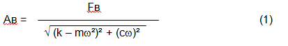
The magnitude of the vibration (e.g. its amplitude Av) depends not only on the excitatory force Fv acting on the mechanism with circular frequency ω, but also on the rigidity k of the mechanism, its mass m, as well as the damping coefficient C.
Various types of sensors can be used to measure vibration and balance mechanisms, including:
- absolute vibration sensors designed to measure vibration acceleration (accelerometers) and vibration velocity sensors;
- sensors of relative vibration - eddy-current or capacitive, designed to measure vibration displacement;
- in some cases (when the design of the mechanism allows it), force sensors can also be used to assess its vibration load; in particular, they are widely used to measure the vibration load of hard-bearing balancing machine supports.
So, vibration is the reaction of a machine to the action of external forces. The magnitude of vibration depends not only on the magnitude of the force acting on the mechanism, but also on the rigidity of the mechanism design. One and the same force can lead to different vibrations. In a hard-bearing machine, even if the vibration is small, the bearings may be subjected to significant dynamic loads. This is why force rather than vibration sensors (vibration accelerometers) are used when balancing hard-bearing machines.
Vibration sensors are used on mechanisms with relatively pliable supports, when the action of unbalanced centrifugal forces leads to a noticeable deformation of supports and vibration. Force sensors are used for rigid supports, when even significant forces due to unbalance do not lead to significant vibration.
Resonance is a factor that prevents balancing
Earlier we mentioned that rotors are divided into rigid and flexible. Stiffness or flexibility of rotor should not be confused with stiffness or mobility of supports (foundation) on which the rotor is installed. A rotor is considered rigid when its deformation (bending) under the action of centrifugal forces can be neglected. Deformation of flexible rotor is relatively large and cannot be neglected.
In this article, we consider only the balancing of rigid rotors. A rigid (non-deformable) rotor can in turn be mounted on rigid or movable (pliable) supports. It is clear that this stiffness/suspendability of supports is also relative, depending on rotor speed and magnitude of resulting centrifugal forces. A conditional boundary is the frequency of natural vibrations of the rotor supports.
For mechanical systems, the shape and frequency of natural vibrations are determined by the mass and the elasticity of the elements of mechanical system. That is, the frequency of natural vibrations is an internal characteristic of the mechanical system and does not depend on external forces. Being deflected from the state of equilibrium, supports due to elasticity tend to return to the position of equilibrium. But due to the inertia of the massive rotor, this process is in the nature of damped oscillations. These vibrations are the natural vibrations of the rotor-support system. Their frequency depends on the ratio of the mass of the rotor to the elasticity of the supports.
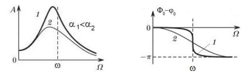
When the rotor begins to rotate and the frequency of its rotation approaches the frequency of natural vibrations, the amplitude of vibration increases sharply, which can lead to the destruction of the structure.
The phenomenon of mechanical resonance occurs. In the area of resonance, a change of rotation speed by 100 rpm may lead to an increase in vibration by tens of times. At the same time (in the resonance area) the vibration phase changes by 180°.
If the design of the mechanism is unsuccessful and the operating frequency of the rotor is close to the frequency of natural vibrations, then the operation of the mechanism becomes impossible because of the inadmissibly high vibration. This is not possible in the usual way, since even a small change in speed will cause a drastic change in the vibration parameters. For balancing in the area of resonance, special methods not considered in this article are used.
It is possible to determine the frequency of natural vibrations of the mechanism at coasting (at switching off the rotor rotation) or by the shock method with the subsequent spectral analysis of the system response to the shock.
For mechanisms, which working frequency of rotation is above the resonance frequency, i.e. working in the supercritical (post-resonant) regime, the supports are considered to be moving and for measurement are used vibration sensors, mainly vibroacelerometers, measuring acceleration of structural elements. For mechanisms operating in preresonant mode, the supports are considered rigid. In this case, force sensors are used.
Linear and nonlinear models of a mechanical system. Non-linearity is a factor that prevents balancing
When balancing rigid rotors, mathematical models called linear models are used for balancing calculations. A linear model means that in such a model, one quantity is proportional (linear) to the other. For example, if the uncompensated mass on the rotor is doubled, then the vibration value will also be doubled. For rigid rotors, a linear model can be used, since they do not deform.
For flexible rotors, the linear model can no longer be used. For a flexible rotor, if the mass of the heavy point increases during rotation, additional deformation will occur, and in addition to the mass, the radius of the location of the heavy point will also increase. Therefore, for a flexible rotor, the vibration will increase more than twofold, and the usual methods of calculation will not work.
Also, the change of elasticity of supports at their large deformations, for example, when at small deformations of supports some structural elements work, and at large ones other structural elements are involved. This is why you cannot balance mechanisms that are not fixed on a foundation, but, for example, simply placed on the floor. With significant vibrations, the force of the imbalance can pull the mechanism off the floor, thereby significantly changing the stiffness characteristics of the system. Motor feet must be securely fastened, bolt mounts must be tightened, washer thickness must provide sufficient mounting rigidity, etc. If the bearings are broken, significant shaft misalignment and shocks are possible, which will also result in poor linearity and an inability to perform a quality balance.
Balancing devices and balancing machines
As noted above, balancing is the process of aligning the main central axis of inertia with the rotor's axis of rotation.
This process can be performed by two methods.
The first method involves machining the rotor trunnions in such a way that the axis passing through the centers of the trunnions crosses the main central axis of inertia of the rotor. Such a technique is rarely used in practice and will not be discussed in detail in this article.
The second (most common) method involves moving, installing or removing correction weights on the rotor, which are placed so that the axis of inertia of the rotor is as close to its axis of rotation as possible.
Moving, adding or removing correction weights during balancing may be accomplished by various technological operations including: drilling, milling, surfacing, welding, screwing or unscrewing, laser or electron beam burning, electrolysis, electromagnetic surfacing, etc.
The balancing process can be accomplished in two ways:
- balancing of assembled rotors (in their own bearings) using balancing machines;
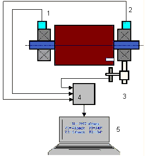
- balancing of rotors on balancing machines. For balancing of rotors in their own bearings usually used specialized balancing devices (kits), which allow measuring the vibration of the balanced rotor at its frequency of rotation in vector form, i.e. to measure both the amplitude and the phase of vibration. At present, the above devices are manufactured on the basis of microprocessor technology and (apart from vibration measurement and analysis) provide automatic calculation of parameters of correcting weights, which should be installed on the rotor to compensate its unbalance.
These devices include:
- a measuring and computing unit based on a computer or industrial controller;
- Two (or more) vibration sensors;
- A phase angle sensor;
- accessories for mounting the sensors on the site;
- specialized software, designed to perform a full cycle of rotor vibration parameters measurement in one, two or more correction planes.
Two types of balancing machines are currently the most common:
- Soft-bearings machines (with soft supports);
- Hard-bearings machines (with rigid supports).
Soft-bearings machines have relatively pliable supports, for example, based on flat springs. The frequency of natural vibrations of these supports is usually 2-3 times lower than the rotation frequency of the balancing rotor, which is mounted on them. Vibration sensors (accelerometers, vibration velocity sensors, etc.) are usually used when measuring the vibration of the machine's preresonant supports.
Pre-resonance balancing machines use relatively rigid supports, whose natural frequencies of vibration should be 2-3 times higher than the rotation frequency of the rotor being balanced. Force transducers are usually used to measure the vibration load of the preresonance machine supports.
The advantage of pre-resonance balancing machines is that balancing on them can be performed at relatively low rotor speeds (up to 400 - 500 rpm), which greatly simplifies the design of the machine and its foundation, and increases the productivity and safety of balancing.
Balancing rigid rotors
Important!
- Balancing only eliminates vibration caused by asymmetrical distribution of the rotor mass relative to its rotational axis. Other types of vibration are not eliminated by balancing!
- Technical mechanisms, whose design ensures the absence of resonances at the operating frequency of rotation, reliably fixed on the foundation, installed in serviceable bearings, are subject to balancing.
- Defective machinery must be repaired before balancing. Otherwise, quality balancing is not possible.
Balancing is no substitute for repair!
The main task of balancing is to find the mass and location of compensating weights that counteract the centrifugal forces.
As mentioned above, for rigid rotors, it is generally necessary and sufficient to install two compensating weights. This will eliminate both static and dynamic unbalance of the rotor. The general scheme for measuring vibration during balancing is as follows.
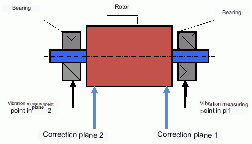
Vibration sensors are installed on the bearing supports at points 1 and 2. A revolution marker is attached to the rotor, usually with reflective tape. The RPM mark is used by the laser tachometer to determine the rotor speed and phase of the vibration signal.
How dynamic balancing is performed (three-run method)
In most cases dynamic balancing is carried out by the method of three starts. The method is based on the fact that test weights of known weight are placed on the rotor in series in plane 1 and 2 and the weights and the location of the balancing weights are calculated based on the results of changes in the vibration parameters.
The place of installation of weights is called the correction plane. Usually the correction planes are selected in the area of the bearing supports on which the rotor is installed.
At the first start-up the initial vibration is measured. Then a test weight of known weight is placed on the rotor closer to one of the bearings. A second start-up is carried out and the vibration parameters are measured, which should change due to the test weight installation. Then the test weight in the first plane is removed and installed in the second plane. A third test run is performed and the vibration parameters are measured. The test weight is removed and the software automatically calculates the masses and installation angles of the balance weights.
The point of installing the test weights is to determine how the system reacts to changes in imbalance. The weights and locations of the test weights are known, so the software can calculate so called influence coefficients, showing how introducing a known imbalance affects the vibration parameters. The influence coefficients are characteristics of the mechanical system itself and depend on the rigidity of the supports and the mass (inertia) of the rotor-support system.
For the same type of mechanisms of the same design the influence coefficients will be close. It is possible to save them in the computer memory and use them for balancing of the same-type mechanisms without test runs, which significantly increases the productivity of balancing. Note that the mass of test weights should be chosen such that the vibration parameters change noticeably when test weights are installed. Otherwise, the error of calculation of influence coefficients increases and the quality of balancing deteriorates.
As you can see from Fig. 1, the centrifugal force acts in the radial direction, i.e. perpendicular to the rotor axis. Therefore, the vibration sensors must be installed so that their axis of sensitivity also points in the radial direction. Usually, the stiffness of the foundation in the horizontal direction is less, so the vibration in the horizontal direction is higher. Therefore, in order to increase the sensitivity, the sensors should be installed so that their axis of sensitivity is also directed horizontally. Although there is no fundamental difference. In addition to vibration in the radial direction, vibration in the axial direction, along the rotor rotation axis, must be monitored. This vibration is usually not caused by unbalance, but by other causes, mainly related to misalignment of the shafts connected through the coupling.
This vibration cannot be eliminated by balancing, in which case alignment is required. In practice, such machines usually have both rotor imbalance and shaft misalignment, which makes the task of eliminating vibration much more difficult. In such cases, it is necessary to center the machine first and then balance it. (Although with strong torque imbalance, vibration also occurs in the axial direction due to "twisting" of the foundation structure.)
Related articles (examples of balancing stands)
- Balancing stand with soft support
- Balancing the rotors of electric motors
- Simple but effective balancing stands
Criteria for assessing the quality of balancing mechanisms
The balancing quality of rotors (mechanisms) can be evaluated in two ways. The first method involves comparing the amount of residual unbalance determined during the balancing process with the tolerance for residual unbalance. These tolerances for the different rotor classes are specified in ISO 21940-11 (formerly ISO 1940-1).
However, compliance with the specified tolerances cannot fully guarantee the operational reliability of the mechanism, associated with the achievement of the minimum level of its vibration. This is explained by the fact that the magnitude of vibration of the mechanism is determined not only by the magnitude of the force associated with the residual unbalance of its rotor, but also depends on several other parameters, including: the rigidity k of the mechanism structural elements, its mass m, the damping factor, as well as the rotation frequency. Therefore, to estimate dynamic qualities of the mechanism (including quality of its balance) in a number of cases it is recommended to estimate the level of residual vibration of the mechanism, which is regulated by a number of standards.
The most common standard, which regulates the admissible levels of vibration of mechanisms is ISO 10816-3-2002. With its help, it is possible to set tolerances for any type of machines, taking into account the power of their electric drive.
In addition to this universal standard, there is a number of specialized standards developed for specific types of machines. For example, ISO 31350-2007, ISO 7919-1-2002, etc.
Standards and references
- ISO 1940-1:2007. Vibration. Requirements for the balancing quality of rigid rotors. Part 1. Determination of permissible imbalance.
- ISO 10816-3:2009. Mechanical vibration — Evaluation of machine vibration by measurements on non-rotating parts — Part 3: Industrial machines with nominal power above 15 kW and nominal speeds between 120 r/min and 15 000 r/min when measured in situ.
- ISO 14694:2003. Industrial fans — Specifications for balance quality and vibration levels.
- ISO 7919-1:2002. Vibration of machines without reciprocating motion — Measurements on rotating shafts and evaluation criteria — General guidance.
FAQ
Does balancing remove all vibration?
No. Balancing removes vibration caused by the asymmetrical distribution of rotor mass relative to its rotational axis. Vibration from misalignment, bearing defects, aerodynamic/hydrodynamic forces, electromagnetic forces, and other causes requires separate diagnostics and corrective actions.
Why can balancing fail near resonance?
Near resonance, small speed changes can cause large changes in vibration amplitude and a 180° phase shift. In such conditions the measurement results become unstable, and conventional balancing procedures may not converge without special methods.
When do you need one-plane vs. two-plane balancing?
For a rigid rotor, two weights separated along the rotor length are generally necessary and sufficient to eliminate combined static and dynamic unbalance. Narrow rotors often exhibit mostly static unbalance, but deformation and geometry can introduce a dynamic component that may require two-plane correction.
What should be done before balancing?
Ensure the machine is serviceable: reliable mounting to the foundation, healthy bearings, no severe looseness, and no obvious sources of non-linearity. Balancing is not a substitute for repair.
Key takeaways
- Balancing corrects mass-related (centrifugal) excitation; it does not solve misalignment, bearing damage, or electromagnetic/aerodynamic sources.
- Resonance and non-linearity can make conventional balancing ineffective or unsafe.
- For rigid rotors, two-plane balancing is the general solution for combined static + dynamic unbalance.