Crusher Balancing: The Professional Guide to Dynamic Vibration Control
Precision dynamic balancing is the single most effective way to prevent catastrophic bearing failure and reduce industrial maintenance costs. By eliminating parasitic centrifugal forces, crusher balancing extends equipment life by 3–5 times and cuts repair costs by up to 80%. This guide details the engineering principles and field procedures for balancing crushers, mills, and high-load rotating machinery using the Balanset-1A vibration analyzer.


Technical Brief & Key Takeaways
At a glance
- Scope: Industrial crusher balancing (jaw, cone, impact, hammer), mill balancing (ball, roller, grinding), shredders, and high-speed mixers.
- Core Problem: Static "knife-edge" checks miss couple imbalance. Spinning rotors generate periodic forces at 1× rotational frequency that accelerate fatigue and loosen structural fasteners.
- Technical Solution: Two-plane in-situ dynamic balancing (balancing in original bearings) using influence-coefficient calculation.
- Performance Targets: Achieving balance quality grade ISO 1940 G6.3 and reducing vibration below 4.5 mm/s (ISO 10816).
Crusher Balancing: Engineering Impact on Reliability and Costs
Key fact
An imbalance of just 100 g on a crusher rotor rotating at 1500 rpm creates a centrifugal force equivalent to approximately 50 hammer blows per second on the bearings. This constant pounding force rapidly degrades bearing integrity and can lead to catastrophic failure.
The Importance of Proper Balancing
Even a small imbalance can have dramatic effects on heavy machinery. For example, just 100 grams of imbalance on a crusher rotor can generate an impact force equivalent to 50 hammer blows per second on the bearings. These constant pounding forces lead to excessive wear. In fact, neglecting balance means bearings might only last 5–10 thousand hours and maintenance costs can skyrocket (e.g. $50–100k per year in repairs). By contrast, a well-balanced machine can make bearings last 30–50 thousand hours and cut repair costs by as much as 50–80%. Reduced vibration also improves energy efficiency (5–15% less power wasted) and minimizes unplanned downtime. Simply put, keeping rotors balanced extends equipment life, saves money, and helps prevent accidents.
Crusher balancing and mill balancing are mandatory maintenance procedures for heavy rotating equipment. The dynamic load from imbalance depends not on the rotor’s total mass, but on the unbalance (equivalent unbalance mass and radius). A useful estimate is F ≈ mu · r · ω², where ω = 2πn/60. At 1000 rpm (ω ≈ 105 rad/s), an unbalance of 1 kg at a 1 m radius produces about 11 kN (~1.1 metric ton‑force). “Several tons” of periodic force would require several kg·m of unbalance (e.g., 10 kg at 0.3 m ≈ 3 kg·m gives ~33 kN ≈ 3.3 metric ton‑force). The load is periodic at the rotational frequency (1000 rpm ≈ 16.7 Hz), so the consequences can escalate progressively:
- Initial stage: Increased noise and vibration levels
- Intermediate stage: Bearing life drops from 30,000–50,000 hours to 5,000–10,000 hours
- Advanced stage: Loosened fasteners, fatigue cracks in welds, structural damage
- Final stage: Catastrophic failure with safety risks and extended downtime
Economic losses from operating unbalanced equipment reach €50,000–100,000 annually in repairs and spare parts alone, plus 10–15 days of unplanned downtime and 5–15% excess energy consumption.
Static vs Dynamic Balancing: Critical Distinctions
Understanding the difference between static and dynamic balancing is essential for selecting the correct method.
Static balancing
Static balancing corrects center-of-mass displacement from the rotation axis. It is sufficient for disk-type rotors where diameter exceeds width by 7–10 times (L/D < 0.25) and speeds below 800 rpm. Static imbalance can be detected without rotation — the heavy side settles downward on knife-edge supports.
Dynamic balancing
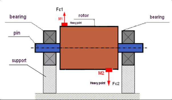
Dynamic balancing corrects both static imbalance and couple (moment) imbalance. It is mandatory for all elongated rotors where width exceeds 30% of diameter. The critical point: a statically balanced rotor can have significant dynamic imbalance. Two unbalanced hammers at opposite rotor ends, 180° apart, create a bending moment during rotation despite static balance being satisfied.
Why Static Balancing “On Knives” Falls Short
A traditional way to check balance is the static “knife-edge” method – placing a rotor on low-friction knife-edge rails or prism stands to see if a heavy spot makes it roll. Static balancing can correct a simple heavy spot (static imbalance) by adding or removing weight so the rotor’s center of mass aligns with its axis. However, this method cannot detect or fix a “moment” (dynamic) imbalance.
In a moment (or couple) imbalance, there are equal heavy spots on opposite ends of the rotor, 180° apart. At rest, these two opposing weights balance each other out, so the rotor might not roll on a knife-edge stand. It appears balanced in static conditions. But when the rotor spins, those two masses create forces (centrifugal forces) in opposite directions on each end, forming a twisting moment that makes the rotor wobble violently.
It’s like having a balanced seesaw that suddenly starts to twist when in motion. No amount of tweaking on a static stand will solve this, because the imbalance only shows up at running speed.
In simple terms, balancing “on knives” only fixes one-plane heavy spots and misses hidden two-plane imbalances. That’s why a rotor can be “statically balanced” but still vibrate in service. To fix a dynamic imbalance, you need to balance in at least two planes (e.g. adding two correction weights at different positions along the rotor) to counteract the twisting forces.
This requires dynamic balancing methods while the rotor is spinning (or data from spinning), which static stands cannot provide.
Dynamic Balancing Solutions
Dynamic balancing involves measuring the rotor’s vibration during rotation and adding weights to counteract both static and couple imbalances. Traditionally, this could be done by removing the rotor and placing it on a specialized balancing machine. In a balancing machine, the rotor is spun and instrumentation determines where weights should go. This achieves a precise balance, but it has drawbacks: disassembling the machine, transporting the rotor to a shop, and days of downtime.
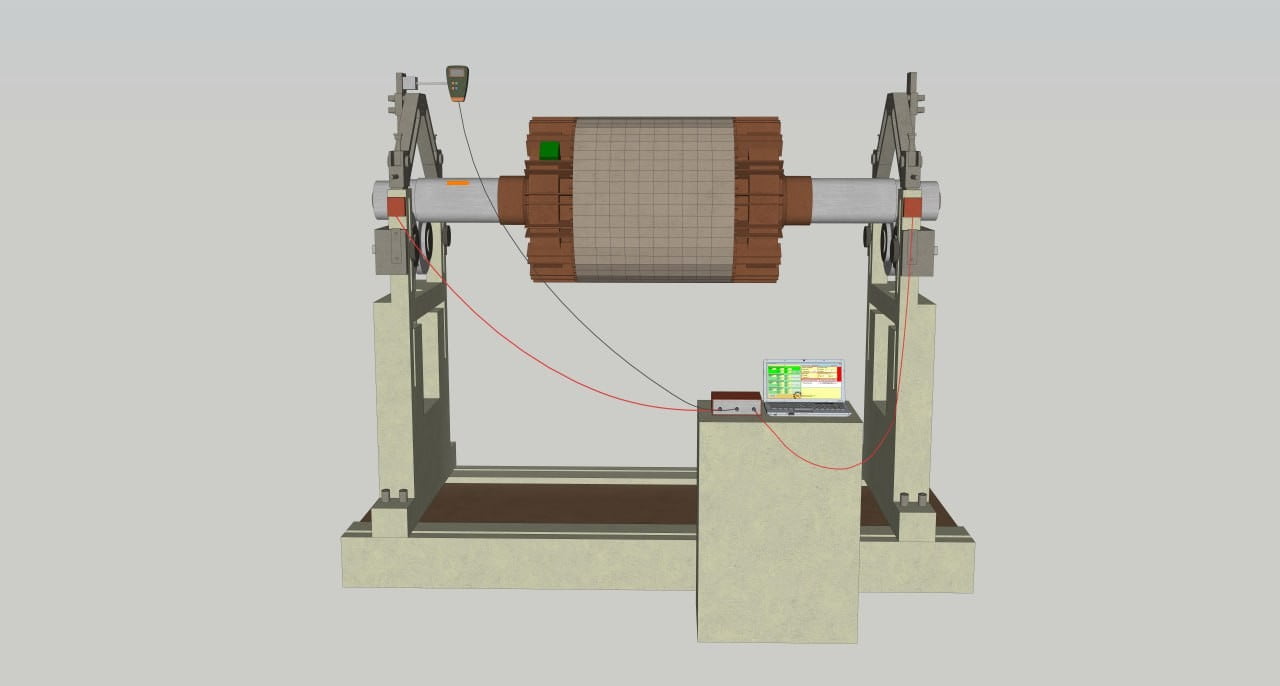
In contrast, modern field-balancing uses portable equipment to balance the rotor in its own bearings (in-situ). A technician attaches vibration sensors to the machine’s housing and a tachometer to measure rotational speed and phase. The machine is run at normal speed, and the equipment (like the Balanset-1A) measures how much and in what direction the rotor is vibrating. By performing a test with a trial weight, the software can calculate the exact counterweight needed and the angle where it should be placed. This influence coefficient method (often a 3-run process with trial weights) automatically computes the solution to achieve balance.
In the end, weights are added (or material is removed) on the rotor to cancel out the imbalance forces.
The dynamic approach addresses both static and dynamic (couple) imbalance because it accounts for the phase of vibration at different points. Unlike the “knife-edge” static method, dynamic balancing in two planes can correct a wobble that only appears when spinning.
Field dynamic balancing is especially useful for large equipment (e.g. big crusher rotors, fans, or mill drums) that are impractical to move to a shop. It minimizes downtime since you don’t fully strip down the machine – often you can balance at the site in a few hours instead of having days of outage.
Equipment Types: Overview
Crusher balancing, mill balancing, and related procedures apply to a wide range of industrial equipment. Each category has specific requirements:
Common Machines Requiring Balancing
Many types of industrial equipment need regular balancing. Some notable examples include:
Crushers: Machines like jaw crusher balancing, cone crusher balancing, impact crusher balancing, and hammer crusher balancing are critical because their heavy rotors or moving parts can create large vibrations if even slightly off-balance. For instance, impact crushers often require regular rebalancing due to wear of blow bars and impact plates.
Hammer crushers and other rock crushers may need balancing whenever hammers or jaw plates are replaced, to ensure the new parts don’t introduce vibration. Even the large flywheels on jaw crushers must stay balanced to avoid resonant shaking.
Mills and Grinders: Hammer mill balancing, ball mill balancing, roller mill balancing, and grinding mill balancing are vital for milling equipment. High-speed rotors in hammer mills and the massive rotating drums in ball mills must be balanced so that grinding is smooth and bearings aren’t overloaded.
A ball mill’s large rotating mass, for example, requires careful balance to prevent undue stress on its supports.
Roller mills and other grinding mills similarly need balance to avoid uneven wear and vibration.
Size Reduction Machines: Equipment such as pulverizers, shredders, chippers, granulators, and pelletizers all have spinning knives, blades, or rollers. Proper pulverizer balancing, shredder balancing, chipper balancing, granulator balancing, and pelletizer balancing ensures these cutters operate without excessive shaking. This is especially important because pieces of material or knives can break or wear during operation, suddenly throwing the rotor out of balance.
Regular balancing keeps these machines running safely even under tough conditions.
Mixers and Agitators: Even mixing equipment benefits from balancing. Mixer balancing, agitator balancing, and stirrer balancing apply to rotating impellers or paddles in industrial mixers. If the mixer’s shaft or impeller is even slightly unbalanced (say due to attached ingredients or wear), it can cause the entire mixer to wobble. Balancing these rotating parts prevents vibrations that could affect product quality and machine integrity.
In all these cases, the goal is the same: a balanced rotor spins smoothly without imparting damaging forces to its bearings or structure. Crusher balancing and mill balancing are particularly important in heavy industries, but the principle extends to any rotating equipment – from huge industrial shredders down to small lab mixers.
| Equipment Type | Typical Speed (RPM) | Balance Grade (ISO 1940) | Primary Challenge |
|---|---|---|---|
| Jaw crushers | 250–350 | G6.3 | Eccentric shaft, flywheel balance |
| Cone crushers | 300–500 | G6.3 | Eccentric assembly, liner wear |
| Impact crushers | 700–1500 | G6.3 | Blow bar wear, material buildup |
| Hammer mills | 600–3600 | G2.5–G6.3 | Free-swinging hammers |
| Ball mills | 15–25 | G6.3 | Variable charge distribution |
| Pulverizers | 500–750 | G2.5 | Classifier rotor, vertical spindle |
Glossary
- Static imbalance: the center of mass is offset from the rotation axis (one-plane problem).
- Couple (moment) imbalance: equal heavy spots at opposite rotor ends create a rocking moment; often requires two-plane balancing.
- 1× vibration: vibration component at the rotational speed (RPM/60), typically dominant for imbalance.
- Influence coefficients: system response parameters used to compute correction weights from trial runs.
- In‑situ balancing: balancing a rotor in its own bearings on the installed machine.
Technical Tolerances and Performance Specifications
Achieving optimal balance requires adherence to strict tolerances specific to each equipment type. These specifications are critical for maintenance planning and quality verification.
Material buildup impact: documented case
Real-world example
Impact crusher processing wet clay: 15 kg of adhered material increased vibration from 4.0 mm/s to 12.0 mm/s — a 3× amplification. Rotor cleaning restored vibration to 4.2 mm/s before balancing correction. This demonstrates the critical importance of thorough cleaning before any balancing procedure.
Critical speed considerations for mixing equipment
Operating speed relative to critical speed determines balancing requirements and safe operating zones:
- Heavy-duty mixers: Operate at 65% critical speed
- Standard industrial mixers: Operate at 70% critical speed
- Paddle/turbine agitators: 50–65% critical speed
- High-speed (propeller, disk) agitators: Above critical speed
- Prohibited zone: 70–130% critical speed without dynamic balancing
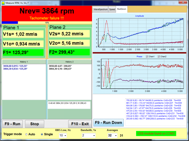
The Balanset-1A "RunDown" function identifies resonant frequencies during coast-down, enabling operators to verify safe operating zones and avoid catastrophic resonance.
Balanset-1A extended specifications
| Parameter | Specification |
|---|---|
| Vibration measurement range | 0.05–100 mm/s RMS |
| Frequency range | 5–550 Hz (up to 1000 Hz) |
| Speed range | 150–90,000 rpm |
| Phase measurement accuracy | ±1° |
| Amplitude measurement accuracy | ±5% |
| Accelerometer sensitivity | 100 mV/g |
| Laser tachometer working distance | 50–500 mm |
| Magnetic mounting force | 60 kgf |
| Complete kit weight | 4 kg in protective case |
ISO vibration zones (ISO 10816-3)
| Zone | Vibration Level (mm/s RMS) | Assessment |
|---|---|---|
| Zone A | <1.8 | Excellent — newly commissioned equipment |
| Zone B | 1.8–4.5 | Acceptable for continuous operation |
| Zone C | 4.5–11.2 | Marginally acceptable — schedule correction |
| Zone D | >11.2 | Unacceptable — immediate action required |
Target after balancing: Zone A or B. Most crushers should achieve <4.5 mm/s with proper two-plane dynamic balancing using Balanset-1A.
Crusher Balancing: Detailed Procedures
Jaw Crusher Balancing
Jaw crusher balancing addresses the eccentric shaft and flywheel assembly. These machines operate like a single-cylinder reciprocating engine, generating normal vibrations at rotation frequency and its second harmonic. However, flywheel wear, loosened counterweight mounting, and eccentric shaft damage lead to pathological imbalance.
Characteristic symptom: longitudinal vibration significantly exceeds vertical vibration. Target: reduce vibration from 50 mm/s to below 7.6 mm/s after correct balancing. Horizontal vibration tolerance: ±2 mm; vertical: ±1 mm.
Cone Crusher Balancing
Cone crusher balancing focuses on the eccentric assembly and crushing cone. Primary issues include uneven liner wear, cone misalignment (tolerance ≤0.1 mm), and eccentric bushing wear. Vibration monitoring shows acceptable performance when horizontal displacement ≤2 mm and vertical ≤1 mm. Body amplitude exceeding 0.5 mm indicates serious malfunction requiring immediate attention.
Impact Crusher Balancing
Impact crusher balancing is the most frequently performed procedure in quarries. Both horizontal shaft impactors (HSI) and vertical shaft impactors (VSI) rely on kinetic impact energy from blow bars striking material at high speed.
Uneven wear problem
Blow bars wear intensively and non-uniformly. Replacing a single blow bar without weight-matching catastrophically disrupts balance. Two-plane balancing is essential for HSI rotors due to their length; single-plane static balancing leaves residual couple imbalance causing skewed bearing loading.
Safety considerations
Rotors possess enormous inertia; start-stop cycles for trial weight installation consume significant time. The Balanset-1A's ability to store influence coefficients means subsequent balancing (after blow bar replacement) requires only one measurement run without trial weights.
VSI specifics
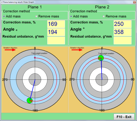
Centrifugal impact crushers demand even higher precision due to rotational speeds reaching 1500–2000 rpm. Imbalance often stems from material buildup inside rotor chambers. VSI balancing frequently requires welding weights onto upper and lower rotor covers. The Balanset-1A efficiently calculates weight installation angles in polar coordinates.
Hammer Crusher Balancing
Hammer crusher balancing is complicated by free-hanging hammers. If one hammer seizes on its pin due to corrosion or dust, it fails to fully extend under centrifugal force, shifting the rotor's center of mass and creating enormous, variable imbalance.
Methodology
Before using Balanset-1A, operators must verify free movement of all hammers and their weight correspondence. Balancing is performed on rotor disks, not hammers themselves. The "Split Weight" function allows distributing calculated mass between two available points (e.g., between hammer pin holes) when exact angle mounting is impossible, preserving the correction vector.
Mill Balancing: Precision Requirements
Mills demand the highest balancing precision due to continuous operation cycles; any vibration leads to fatigue failure of expensive drives and liners.
Hammer Mill Balancing
Unlike crushers, hammer mill balancing addresses high-speed units (up to 3600 rpm) used for fine grinding of grain, biomass, or chemicals. At such speeds, permissible residual imbalance is extremely small (ISO 1940 G2.5 or G6.3). Hammer mill rotors often function as fans; opening the housing to install weights can alter aerodynamic resistance. Balancing with Balanset-1A must be conducted with housing fully assembled, using access ports, or accounting for changed conditions.
Ball Mill Balancing
Ball mill balancing presents unique challenges. The drum itself, with its chaotic grinding media motion, typically cannot be balanced in the conventional sense. The focus is the high-speed drive train.
Pinion shaft balancing
The drive shaft with bearing assemblies and coupling is the critical element. Vibration on the pinion shaft is often caused not by imbalance but by tooth wear or misalignment. Balanset-1A's spectral analysis identifies gear mesh frequency (GMF). If 1×RPM dominates, dynamic balancing of the coupling or flange-mounted weights is performed.
Measurement complexities
Ball impacts inside the drum create random low-frequency noise. Balanset-1A settings must increase signal averaging time (e.g., 10–20 seconds) to obtain stable amplitude and phase readings.
Roller Mill Balancing
Roller mill balancing applies to flour milling, polymer, and steel industries. Rollers are long, heavy cylinders prone to bending (whip). Two-plane balancing at the ends is mandatory. Balanset-1A measures phase difference between left and right supports; 180° phase difference indicates strong couple imbalance. In-situ roller balancing accounts for drive pulleys and gears mounted on roller journals, which contribute their own imbalance.
Grinding Mill Balancing
Grinding mill balancing encompasses a broad spectrum: attritors, bead mills, and precision grinding machines. For fine grinding spindles, the device supports three-movable-counterweight methodology, achieving ideal smoothness without welding or putty.
Pulverizer Balancing
Pulverizer balancing, particularly for coal mills in power stations, is mission-critical. Many pulverizers have vertical configurations; vibration sensors (X and Y axes) are mounted on the upper bearing assembly of the motor or gearbox. The upper section houses a rotating separator (dynamic classifier); its imbalance causes severe upper-structure vibration. Balanset-1A balances this assembly through service ports, preventing drive destruction and improving grind fineness.
Size Reduction Equipment Balancing
Shredder Balancing
Shredder balancing addresses massive low-speed rotors (300–500 rpm) processing scrap metal or tires. The Balanset-1A accelerometers have excellent low-frequency sensitivity (from 5 Hz), confidently handling such machines. Due to extreme impact loads, trial and correction weights must be welded securely; magnets or adhesive tape are unacceptable even for testing.
Chipper Balancing
Chipper balancing in forestry distinguishes two machine types. Disc chippers present challenges because the disc acts as a gyroscope, with primary issues being axial vibration ("figure-8" wobble). Sensors are mounted radially and axially (along shaft axis) to monitor disc runout. Weights install on the disc's rear surface or in dedicated balancing pockets.
Drum chippers require classic two-plane balancing due to rotor length. All knives must be serviced as a set — sharpening or replacing one knife disrupts balance. Knife thickness tolerance: 0.13–0.25 mm. Dull knives create chopping rather than cutting action, generating excessive vibration and fatigue cracks in welds. Recommended sharpening interval: every 6–8 operating hours.
Granulator Balancing
Granulator balancing for plastics recycling involves rotor-mounted knives (1–3 mm gap to stationary knives). Upon vibration onset, first check knife condition and mounting. If vibration persists, professional rotor balancing is required. Installing the machine on vibration-damping pads reduces foundation transmission.
Pelletizer Balancing
Pelletizer balancing covers the ring die and pressing rollers. Die face runout must not exceed 0.3 mm (dial indicator check). Roller-to-die gap: minimum 0.2–0.3 mm. Damaged clamping rings are the primary cause of die breakage and severe vibration.
Mixing and Agitation Equipment Balancing
Mixer Balancing
Mixer balancing for industrial-class pumps follows API 610 standard, requiring G2.5 accuracy per ISO 1940. Optimal impeller-to-tank diameter ratio (D/T): 1/3. Heavy-duty mixers operate at 65% critical speed; standard industrial mixers at 70%. Operation in the 70–130% critical speed range without dynamic balancing is prohibited.
Agitator Balancing
Agitator balancing in chemical processing accounts for long shafts in deep vessels. Paddle and turbine agitators operate at 50–65% critical speed; high-speed types (propeller, disk) operate above critical. Dynamic balancing permits safe operation at 70% critical speed. Long shafts employ intermediate supports (stabilizing bearings).
Stirrer Balancing
Stirrer balancing addresses high-speed dispersers (dissolvers). Imbalance causes blade-to-vessel wall contact. Precise shaft and blade balancing with Balanset-1A extends mechanical seal life, preventing product leakage.
Field Balancing with Balanset-1A
The Balanset-1A portable balancing system enables on-site correction without machine disassembly, eliminating transport time, reducing downtime, and allowing result verification under actual operating conditions.
How Balanset-1A Balances Crushers and More
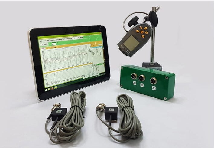
The Balanset-1A is a portable dual-channel dynamic balancer and vibration analyzer designed for exactly this purpose. It allows engineers and maintenance crews to perform precision balancing on-site for a wide range of equipment. Balanset-1A comes with two accelerometer vibration sensors and a laser tachometer, plus software that runs on a PC. Here’s how it works and why it’s effective:
In-Situ Two-Plane Balancing
The Balanset-1A can perform single-plane or two-plane balancing on the actual machine, in its normal bearings. This means you can balance a crusher’s rotor without removing it, saving enormous time. By using two planes, it corrects both static and dynamic imbalance in the rotor. For example, if a cone crusher’s eccentric weight is causing vibration, Balanset-1A’s two-plane capability will identify how to counterweight it in the correct positions — something one-plane methods can’t do.
Wide Range of Equipment
This device is versatile – it’s designed for field balancing of rotating equipment including crushers, fans, mulchers, augers, shafts, centrifuges, turbines, and more. In practice, one Balanset-1A can service a broad equipment fleet (crushers, mills, shredders, mixers, etc.), reducing downtime and dependence on external balancing services.
Easy to Use Software
You don’t have to be a vibration expert to use Balanset-1A. Its software guides the user through a step-by-step procedure and automatically calculates the required correction weights and angles. After a trial weight is tested, it provides the balancing solution clearly, so technicians can become proficient with minimal training.
Reliable Results
Despite its portability, Balanset-1A delivers professional balance quality. It measures vibration and phase accurately and calculates corrections to meet standard balance quality grades (ISO 1940). In practice, it can produce results comparable to far more expensive analyzers when measurement conditions are stable and the procedure is followed correctly.
Vibration Analysis Features
Beyond balancing, Balanset-1A also functions as a vibration analyzer and can display waveforms and FFT spectra. This helps diagnose whether vibration is due to imbalance or other issues (misalignment, looseness, resonance), supporting more accurate maintenance decisions. In balancing mode, the focus is on the 1× rotational component to isolate imbalance.
Advantages of Balanset-1A Over Traditional Methods
Using Balanset-1A for dynamic balancing offers several key advantages compared to older methods or relying on outside services:
No Disassembly & Minimal Downtime: Traditional balancing often meant dismantling the rotor and shipping it to a shop, taking days. With Balanset-1A, balancing is done in-place in a matter of hours
There’s no need to remove the crusher’s rotor or mill shaft; you simply attach the sensors and go through the balancing procedure on-site. This in-situ approach can cut a 3–7 day job down to 2–4 hours, meaning production can resume the same day.
Cost Savings: By doing the work internally, companies avoid the hefty fees of specialist contractors and the losses from extended downtime. The Balanset-1A device itself is relatively affordable – roughly on the order of a few thousand Euros – yet it provides about “80% of the capabilities of expensive analyzers for only ~20% of the cost”
Users can balance by themselves without third-party specialists, and the device can pay for itself after a few balancing jobs. Moreover, preventing a single major failure can justify the investment.
Addresses All Imbalance Types: Unlike static balancing on knife edges, the two-plane dynamic capability of Balanset-1A fixes both static heavy spots and dynamic couple imbalance in one process
This means even if a rotor has that tricky wobble (moment imbalance), Balanset-1A can detect it and guide the placement of two correction weights to cancel out the couple. It’s a comprehensive solution for common imbalance scenarios.
Versatility for Many Machines: One Balanset-1A unit can be used on virtually any rotating part in any industry. It’s truly universal – the same kit can balance a fan blower today, a rock crusher tomorrow, and a pulverizer the next day
In our context, this is ideal for operations that have multiple types of equipment (crushing, grinding, mixing, etc.), as you don’t need separate balancing tools for each. From crushers and grinders to mulchers, mixers, shafts, and turbines, the device adapts to a wide range of rotors.
Ease of Use and Safety: Balanset-1A’s guided software and straightforward hardware setup mean that you don’t need a PhD in vibrations to perform a balance. The process is safe and repeatable – you gradually reduce vibration with calculated weight adjustments, rather than trial-and-error guesswork. This reduces the chance of human error. And by eliminating excessive vibration, you also enhance safety in the facility (fewer instances of machines shaking themselves apart or creating flying debris)
By eliminating excessive vibration, you also enhance safety in the facility (fewer instances of machines shaking themselves apart or creating flying debris).
Fast Diagnostics: With its vibration analyzer mode, the Balanset-1A can also be used to quickly diagnose if imbalance is the main issue or if other factors (like a bent shaft or resonance) are contributing. This all-in-one diagnostic and correction capability means problems are identified and solved faster than waiting for an outside team. An on-site diagnosis and correction cycle can be completed in under 1 hour in many cases
In many cases, the diagnosis + correction cycle can be completed within the same maintenance window.
Technical specifications
| Parameter | Value |
|---|---|
| Vibration measurement range | 0.05–100 mm/s RMS |
| Frequency range | 5–550 Hz (up to 1000 Hz) |
| Speed range | 150–90,000 rpm |
| Phase accuracy | ±1° |
| Amplitude accuracy | ±5% |
| Channels | 2 (simultaneous measurement) |
| Weight | 4 kg (complete kit in case) |
Advantages over traditional methods
| Parameter | Traditional (shop) method | Field balancing (Balanset-1A) |
|---|---|---|
| Total time | 3–7 days | 2–4 hours |
| Disassembly required | Yes | No |
| Typical cost per job | €5,000–15,000 | €500–1,500 |
| Accounts for actual mounting | No | Yes |
| Achievable accuracy | G2.5–G6.3 | G2.5–G6.3 |
Step-by-Step Balancing Procedure
Success in balancing is 80% preparation. Follow this proven algorithm:
Preparation
- Clean rotor of dirt, rust, adhered material — contamination distorts results
- Inspect bearings (play, noise, heat) — balancing cannot correct bearing defects
- Verify secure foundation mounting and check protective guards
- For hammer crushers: verify free hammer movement and weight matching
Sensor installation
- Mount vibration sensors on bearing housings perpendicular to rotation axis (within 25 cm of bearing)
- Connect to X1 and X2 inputs
- Mount laser tachometer so beam strikes reflective tape on rotor
- Connect to X3 input and verify stable RPM reading

Initial measurement
- Launch software: F7 — Balancing → F3 — Two-Plane Balancing
- Enter rotor parameters
- Press F9 to measure initial vibration
- Record amplitude and phase at both measurement points
Trial runs
- Stop machine and install trial weight in Plane 1 (mass should change amplitude or phase by 20–30%)
- Run and measure
- Move weight to Plane 2 and repeat measurement
- Software calculates influence coefficients

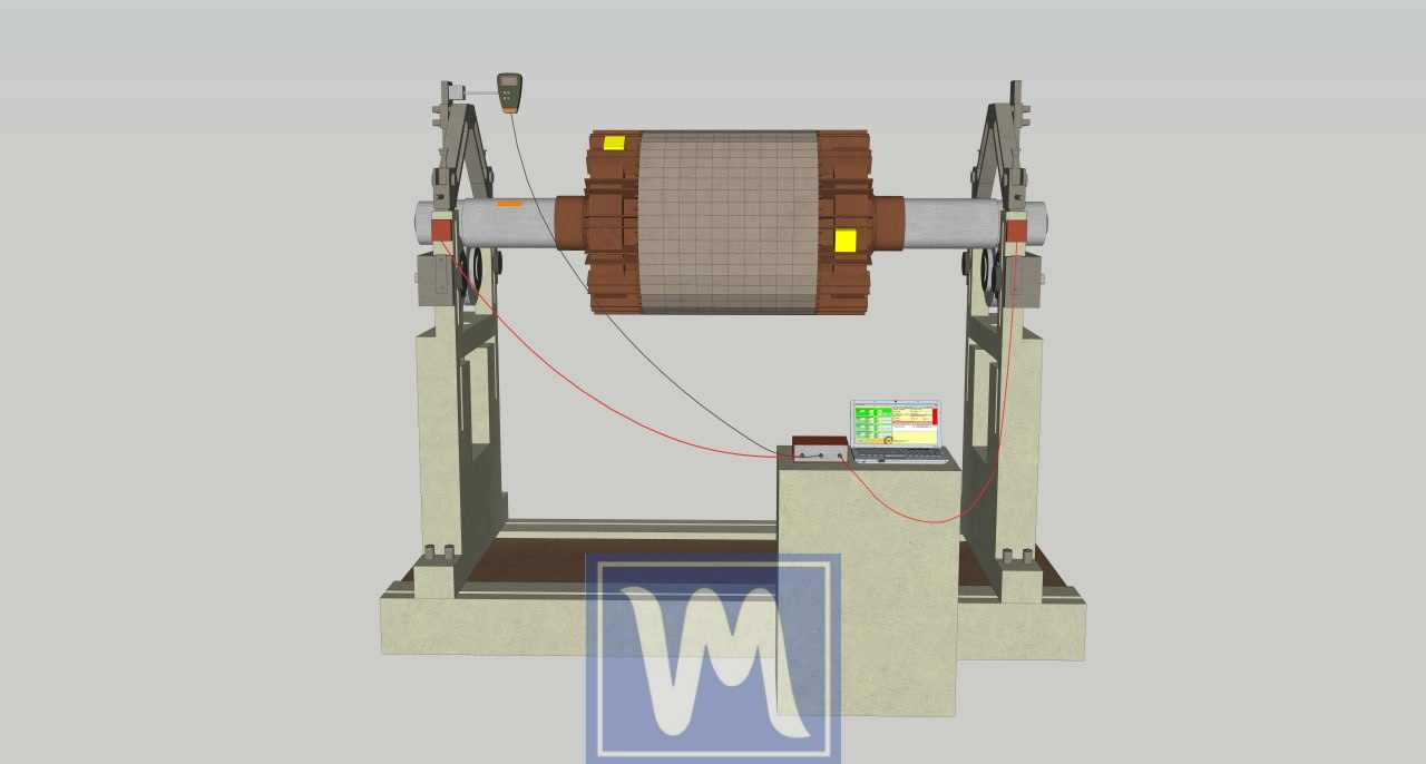
Correction weight installation
- Software displays correction mass and angle for both planes on polar diagram
- Install permanent weights (welding, bolting, clamping)
- Use "Split Weight" function if exact angle mounting is impossible
Verification
- Measure residual vibration
- Target: Zone A or B per ISO 10816 (<2.8 mm/s for most crushers)
- Save influence coefficients (F8) for future balancing without trial runs
- Generate report (F9)
Economic Justification and ROI
Investment in portable balancing equipment pays for itself within 3–4 months of intensive use.
| Item | Value |
|---|---|
| Balanset-1A equipment cost | €1,751–1,975 |
| Single contractor balancing service | €1,500 |
| Typical annual balancing frequency | 4 times/year |
| Annual service contract savings | €6,000 |
| Bearing life extension savings | €10,000–30,000/year |
| Downtime reduction savings | €50,000–150,000/year |
| Total annual savings | €66,000–186,000 |
| Payback period | 3–4 months |
Bearing life physics
L₁₀ bearing life is inversely proportional to the cube of load (P): L₁₀ = (C/P)³. Reducing vibrational load by 50% increases calculated bearing life 8-fold. For heavily loaded assemblies like hammer crusher shafts or roller mill journals, this translates to years instead of months.
Troubleshooting Common Problems
Problem: Unstable or "floating" readings
Possible causes: mechanical looseness, worn bearings, operation near resonance, unstable speed, material buildup.
Solution: Tighten foundation bolts, inspect bearings for play, verify rigid mounting, ensure constant RPM during measurement, clean rotor thoroughly.
Problem: Cannot achieve required tolerance
Possible causes: other defects present (misalignment, bent shaft, bearing damage), non-linear system behavior, resonance.
Solution: Perform coast-down test to identify resonances, conduct comprehensive diagnostics, correct related defects before re-attempting balance.
Problem: Hammer crusher — hammers seizing on pins
Cause: corrosion or dust preventing free hammer swing.
Solution: Clean and lubricate all hammer pins before balancing. Verify free movement of each hammer. Replace seized pins.
Problem: Impact crusher — material buildup
Cause: wet or sticky material adhering inside rotor chambers (documented case: 15 kg clay increased vibration from 4 to 12 mm/s).
Solution: Thoroughly clean rotor interior before balancing. Consider anti-stick coatings for rotor chambers.
Frequently Asked Questions
How often should crusher balancing be performed?
For impact and hammer crushers: every 500–1000 operating hours or after wear part replacement. For jaw and cone crushers: every 3–6 months or when vibration increases. Continuous vibration monitoring enables condition-based scheduling.
Can in-house personnel perform balancing?
Yes. With Balanset-1A and brief training (typically one day), maintenance technicians without prior balancing experience achieve professional results. The software guides users step-by-step through the procedure.
What balance quality grade is required?
Most crushers and mills: G6.3 per ISO 1940-1. High-speed equipment (hammer mills above 1500 rpm, pulverizers): G2.5. Precision grinding spindles: G1.0 or better.
Does balancing eliminate all vibration?
No. Balancing removes vibration from mass asymmetry only. Vibration from misalignment, bearing defects, looseness, resonance, gear mesh problems, or aerodynamic forces requires separate corrective actions. Comprehensive vibration analysis identifies root causes.
Why is two-plane balancing necessary?
Long rotors (L/D > 0.25) develop both static and couple (moment) imbalance. Single-plane balancing cannot correct couple imbalance, which creates a rocking motion damaging bearings. Two-plane dynamic balancing is the only complete solution.
Can stored influence coefficients be reused?
Yes, for identical rotor configurations. After initial characterization, subsequent balancing (e.g., after blow bar or hammer replacement) requires only one measurement run. This feature dramatically reduces balancing time for routine maintenance.
What is the target vibration level after balancing?
ISO 10816-3 defines zones: Zone A (excellent) <1.8 mm/s, Zone B (acceptable) 1.8–4.5 mm/s, Zone C (marginally acceptable) 4.5–11.2 mm/s, Zone D (unacceptable) >11.2 mm/s. Target: Zone A or B for continuous operation.
Start Saving on Repairs Today
Purchase the Balanset-1A, train your team, and implement condition-based maintenance. Professional technical support available via WhatsApp.
Practical Results: Documented Case Studies
- Sugar cane fiberizer (24 tons, 747 rpm): Vibration reduced from 3.2 to 0.47 mm/s — 6.8× improvement
- Crusher in Spain: Initial vibration >100 mm/s (emergency level), post-balance 16–18 mm/s — machine operates "like new"
- Industrial crusher: Vibration from 21.5 to 1.51 mm/s — 14× improvement
- Roof-mounted fan (-6°C ambient): From 6.8 to <1.8 mm/s
- Shopping center ventilation: Noise reduction 5–7 dB, energy savings, extended service life
Conclusion
In summary, whether it’s jaw crushers, cone crushers, impact crushers, hammer crushers, or other rotating machinery like mills, shredders, mixers, and grinders, keeping the equipment balanced is essential. It leads to smoother operation, longer-lasting components, energy savings, and safer working conditions. Traditional static methods like balancing “on knives” have limitations – they cannot address certain types of imbalance that only reveal themselves when the machine is running. Fortunately, modern dynamic balancing tools offer a solution.
The Balanset-1A portable balancer exemplifies the advancement in this field. It brings professional-grade two-plane balancing directly to the worksite, enabling maintenance crews to quickly correct imbalance in crusher rotors and many other applications. By using intelligent software and sensors, it takes the guesswork out of balancing and ensures even complex imbalances are resolved. The result is machinery that runs as smoothly as intended, free of the destructive forces that vibration causes.
For a broad range of industries – from mining and quarries (crushers and mills) to manufacturing and agriculture (fans, chippers, mixers) – investing in proper balancing equipment like the Balanset-1A can be a game-changer. It protects your machinery “from the inside,” preventing damage before it happens. In practical terms, that means fewer breakdowns, lower maintenance costs, and more reliable production.
From a practical maintenance standpoint, the Balanset-1A fills a useful niche between expensive laboratory equipment and third‑party contractor services: it enables in‑situ balancing in the machine’s own bearings, at real operating speed and load. This matters because laboratory balancing on ideal supports cannot fully reflect site‑specific installation conditions. In addition, stored influence coefficients enable repeat balancing after blow bar or hammer replacement in a single run — without trial weights.
For most crusher and mill equipment, a typical target is balance quality grade G6.3 per ISO 1940, corresponding to vibration below 4.5 mm/s per ISO 10816. Achieving this level with Balanset‑1A is a realistic, reproducible task for qualified personnel after minimal training, provided the machine is mechanically sound and measurements are stable.

0 Comments