بالانس کردن محور محرک: راهنمای جامع
دستگاههای بالانس دینامیکی میللنگها و سیستم اندازهگیری برای ماشینهای بالانس Balanset-4 – 6,803 یورو
تصور کنید که در حال رانندگی با کامیون هستید و ناگهان هنگام شتابگیری یا تعویض دنده، لرزش شدیدی احساس میکنید یا صدای تقتق بلندی میشنوید. این چیزی بیش از یک مزاحمت است - میتواند نشانهی عدم تعادل میل گاردان باشد. برای مهندسان و تکنسینها، چنین لرزشها و صداهایی نشاندهندهی کاهش راندمان، افزایش سرعت فرسایش قطعات و در صورت عدم رسیدگی، خرابیهای پرهزینهی بالقوه است.
در این راهنمای جامع، ما راهحلهای عملی برای مشکلات بالانس میل گاردان ارائه میدهیم. شما یاد خواهید گرفت که میل گاردان چیست و چرا به بالانس نیاز دارد، نقصهای رایجی که باعث لرزش یا سر و صدا میشوند را تشخیص دهید و یک فرآیند گام به گام واضح را برای بالانس دینامیکی میل گاردان دنبال کنید. با به کارگیری این بهترین شیوهها، میتوانید در هزینههای تعمیرات صرفهجویی کنید، زمان عیبیابی را کاهش دهید و اطمینان حاصل کنید که ماشینآلات یا وسیله نقلیه شما با حداقل لرزش به طور قابل اعتمادی کار میکند.
Table of Contents
- 1. Types of Driveshafts
- 2. Universal Joint Drive Malfunctions
- 3. Driveshaft Balancing
- 4. Modern Balancing Machines for Driveshafts
- 5. Preparation for Driveshaft Balancing
- 6. Driveshaft Balancing Procedure
- 7. Recommended Balancing Accuracy Classes for Rigid Rotors


1. Types of Driveshafts
A universal joint drive (driveshaft) is a mechanism that transmits torque between shafts that intersect at the center of the universal joint and can move relative to each other at an angle. In a vehicle, the driveshaft transmits torque from the gearbox (or transfer case) to the driven axles in the case of a classical or all-wheel-drive configuration. For all-wheel-drive vehicles, the universal joint usually connects the driven shaft of the gearbox to the drive shaft of the transfer case, and the driven shafts of the transfer case to the drive shafts of the main drives of the driven axles.
واحدهای نصب شده روی شاسی (مانند گیربکس و جعبه دنده کمکی) میتوانند به دلیل تغییر شکل تکیهگاههایشان و خود شاسی، نسبت به یکدیگر حرکت کنند. در همین حال، محورهای محرک از طریق سیستم تعلیق به شاسی متصل شدهاند و میتوانند به دلیل تغییر شکل عناصر الاستیک سیستم تعلیق، نسبت به شاسی و واحدهای نصب شده روی آن حرکت کنند. این حرکت نه تنها میتواند زاویه میل گاردانهای متصل کننده واحدها، بلکه فاصله بین واحدها را نیز تغییر دهد.
The universal joint drive has a significant disadvantage: the non-uniform rotation of the shafts. If one shaft rotates uniformly, the other does not, and this non-uniformity increases with the angle between the shafts. This limitation prevents the use of a universal joint drive in many applications, such as in the transmission of front-wheel-drive vehicles, where the main issue is transmitting torque to the turning wheels. This disadvantage can be partially compensated by using double universal joints on one shaft, which are turned a quarter of a turn relative to each other. However, in applications requiring uniform rotation, constant velocity joints (CV joints) are typically used instead. CV joints are a more advanced but also more complex design serving the same purpose.
Universal joint drives can consist of one or more universal joints connected by driveshafts and intermediate supports.
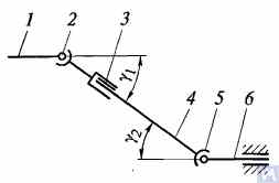
Figure 1. Diagram of a universal joint drive: 1, 4, 6 — driveshafts; 2, 5 — universal joints; 3 — compensating connection; u1, u2 — angles between shafts
به طور کلی، یک درایو مفصل یونیورسال از مفاصل یونیورسال ۲ و ۵، میل گاردانهای ۱، ۴ و ۶ و یک اتصال جبرانی ۳ تشکیل شده است. گاهی اوقات میل گاردان روی یک تکیهگاه میانی متصل به عضو عرضی شاسی خودرو نصب میشود. مفاصل یونیورسال انتقال گشتاور بین شفتهایی را که محورهایشان با زاویهای متقاطع هستند، تضمین میکنند. مفاصل یونیورسال به انواع سرعت غیر یکنواخت و سرعت ثابت تقسیم میشوند. مفاصل سرعت غیر یکنواخت نیز به انواع الاستیک و صلب طبقهبندی میشوند. مفاصل سرعت ثابت میتوانند از نوع گوی با شیارهای جداکننده، نوع گوی با اهرم جداکننده و نوع بادامک باشند. آنها معمولاً در درایو چرخهای کنترلشدهی پیشرو نصب میشوند، جایی که زاویه بین شفتها میتواند به ۴۵ درجه برسد و مرکز مفصل یونیورسال باید با نقطه تقاطع محورهای چرخش چرخ و محور چرخش آن مطابقت داشته باشد.
اتصالات یونیورسال الاستیک به دلیل تغییر شکل الاستیک عناصر اتصال، گشتاور را بین شفتهایی با محورهای متقاطع با زاویه ۲...۳ درجه منتقل میکنند. یک اتصال سرعت غیریکنواخت صلب، گشتاور را از یک شفت به شفت دیگر از طریق اتصال متحرک قطعات صلب منتقل میکند. این اتصال از دو یوغ - ۳ و ۵ - تشکیل شده است که در سوراخهای استوانهای قرار دارند و انتهای A، B، V و G عنصر اتصال - صلیب ۴ - روی یاتاقانها نصب شدهاند. یوغها به طور صلب به شفتهای ۱ و ۲ متصل شدهاند. یوغ ۵ میتواند حول محور BG صلیب بچرخد و همزمان، همراه با صلیب، حول محور AV بچرخد و در نتیجه انتقال چرخش از یک شفت به شفت دیگر را با زاویه متغیر بین آنها امکانپذیر کند.
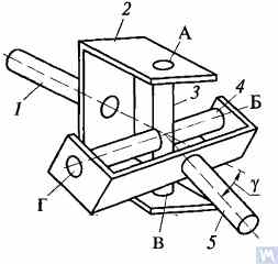
Figure 2. Diagram of a rigid non-uniform velocity universal joint
If shaft 7 rotates around its axis by an angle α, then shaft 2 will rotate by an angle β over the same period. The relationship between the rotation angles of shafts 7 and 2 is determined by the expression tanα = tanβ * cosγکه در آن γ زاویهای است که محورهای شفتها در آن قرار گرفتهاند. این عبارت نشان میدهد که زاویه β گاهی اوقات کمتر، مساوی یا بزرگتر از زاویه α است. برابری این زوایا در هر ۹۰ درجه چرخش شفت ۷ رخ میدهد. بنابراین، با چرخش یکنواخت شفت ۱، سرعت زاویهای شفت ۲ غیر یکنواخت است و طبق قانون سینوسی تغییر میکند. غیر یکنواختی چرخش شفت ۲ با افزایش زاویه γ بین محورهای شفت، قابل توجهتر میشود.
If the non-uniform rotation of shaft 2 is transmitted to the shafts of the units, additional pulsating loads will occur in the transmission, increasing with the angle γ. To prevent the non-uniform rotation of shaft 2 from being transmitted to the unit shafts, two universal joints are used in the universal joint drive. They are installed so that the angles γ1 and γ2 are equal; the forks of the universal joints, fixed on the non-uniformly rotating shaft 4, should be positioned in the same plane.
طراحی قطعات اصلی درایوهای مفصل یونیورسال در شکل 3 نشان داده شده است. یک مفصل یونیورسال با سرعت غیر یکنواخت از دو یوغ (1) تشکیل شده است که توسط یک صلیب (3) به هم متصل شدهاند. یکی از یوغها گاهی اوقات دارای یک فلنج است، در حالی که دیگری به لوله میل گاردان جوش داده شده یا دارای یک انتهای خاردار (6) (یا غلاف) برای اتصال به میل گاردان است. سرمحورهای صلیبی در چشم هر دو یوغ روی یاتاقانهای سوزنی (7) نصب شدهاند. هر یاتاقان در یک محفظه (2) قرار دارد و در چشم یوغ با یک درپوش نگه داشته میشود که با دو پیچ که توسط زبانههای روی واشر قفل شدهاند به یوغ متصل میشود. در برخی موارد، یاتاقانها با حلقههای فنری در یوغها محکم میشوند. برای حفظ روانکاری در یاتاقان و محافظت از آن در برابر آب و خاک، یک آببندی لاستیکی خود سفت شونده وجود دارد. حفره داخلی صلیب از طریق یک اتصال گریس با گریس پر میشود که به یاتاقانها میرسد. این صلیب معمولاً دارای یک شیر اطمینان است تا از آسیب دیدن آببند در اثر فشار گریس پمپ شده به داخل صلیب جلوگیری کند. اتصال خاردار (6) با استفاده از اتصالات گریس (5) روغنکاری میشود.
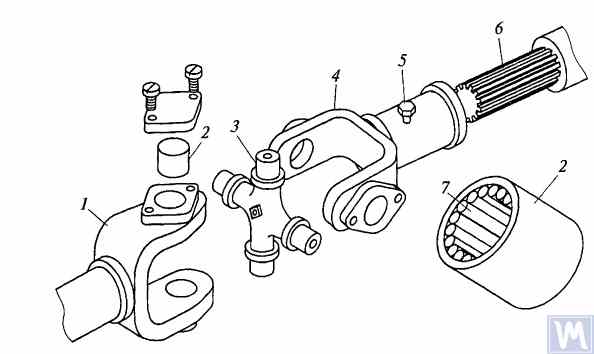
Figure 3. Details of a rigid non-uniform velocity universal joint
حداکثر زاویه بین محورهای شفتهایی که توسط اتصالات یونیورسال با سرعت غیر یکنواخت و صلب به هم متصل شدهاند، معمولاً از 20 درجه تجاوز نمیکند، زیرا راندمان در زوایای بزرگتر به طور قابل توجهی کاهش مییابد. اگر زاویه بین محورهای شفت در محدوده 0...2% تغییر کند، سرمحورهای صلیبی توسط یاتاقانهای سوزنی تغییر شکل میدهند و باعث میشوند که اتصال یونیورسال به سرعت از کار بیفتد.
در گیربکسهای وسایل نقلیه زنجیری پرسرعت، اغلب از اتصالات یونیورسال با انواع کوپلینگ دندهای استفاده میشود که امکان انتقال گشتاور بین شفتهایی با محورهای متقاطع با زاویه تا ۱.۵...۲ درجه را فراهم میکنند.
Driveshafts are typically made tubular, using special steel seamless or welded tubes. The yokes of the universal joints, splined sleeves, or tips are welded to the tubes. To reduce the transverse loads acting on the driveshaft, dynamic balancing is performed with the universal joints assembled. Imbalance is corrected by welding balancing plates to the driveshaft or sometimes by installing balancing plates under the bearing caps of the universal joints. The relative position of the splined connection parts after assembly and balancing of the universal joint drive at the factory is usually marked with special labels.
The compensating connection of the universal joint drive is usually made in the form of a splined connection, allowing axial movement of the universal joint drive parts. It consists of a splined tip that fits into the splined sleeve of the universal joint drive. Lubrication is introduced into the splined connection through a grease fitting or applied during assembly and replaced after prolonged use of the vehicle. A seal and a cover are typically installed to prevent grease leakage and contamination.
For long driveshafts, intermediate supports are usually used in universal joint drives. An intermediate support typically consists of a bracket bolted to the vehicle frame cross member, in which a ball bearing is mounted in a rubber elastic ring. The bearing is sealed on both sides with caps and has a lubrication device. The elastic rubber ring helps to compensate for assembly inaccuracies and bearing misalignment that may occur due to frame deformations.
A universal joint with needle bearings (Figure 4a) consists of yokes, a cross, needle bearings, and seals. The cups with needle bearings are fitted onto the trunnions of the cross and sealed with seals. The cups are secured in the yokes with snap rings or caps fastened with screws. Universal joints are lubricated through a grease fitting via internal drillings in the cross. A safety valve is used to eliminate excess oil pressure in the joint. During uniform rotation of the driving yoke, the driven yoke rotates non-uniformly: it advances and lags behind the driving yoke twice per revolution. To eliminate non-uniform rotation and reduce inertial loads, two universal joints are used.
In the drive to the front driving wheels, constant velocity universal joints are installed. The constant velocity joint drive of GAZ-66 and ZIL-131 vehicles consists of yokes 2, 5 (Figure 4b), four balls 7, and a central ball 8. The driving yoke 2 is integral with the inner axle shaft, while the driven yoke is forged together with the outer axle shaft, at the end of which the wheel hub is fixed. The driving moment from yoke 2 to yoke 5 is transmitted through balls 7, which move along circular grooves in the yokes. The central ball 8 serves to center the yokes and is held in place by studs 3, 4. The rotation frequency of yokes 2, 5 is the same due to the symmetry of the mechanism relative to the yokes. The change in shaft length is ensured by the free splined connections of the yokes with the shaft.
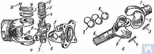
Figure 4. Universal Joints: a — universal joint: 1 — cap; 2 — cup; 3 — needle bearing; 4 — seal; 5, 9 — yokes; 6 — safety valve; 7 — cross; 8 — grease fitting; 10 — screw; b — constant velocity universal joint: 1 — inner axle shaft; 2 — driving yoke; 3, 4 — studs; 5 — driven yoke; 6 — outer axle shaft; 7 — balls; 8 — central ball
2. Universal Joint Drive Malfunctions
Universal joint drive malfunctions typically manifest as sharp knocks in the universal joints that occur when the vehicle is moving, especially during shifts between gears and sudden increases in the engine crankshaft speed (for example, when transitioning from engine braking to acceleration). A sign of universal joint malfunction can be its heating to a high temperature (over 100°C). This happens due to significant wear of the bushings and trunnions of the universal joint, needle bearings, crosses, and splined connections, resulting in misalignment of the universal joint and significant impact axial loads on the needle bearings. Damage to the cork seals of the universal joint cross leads to rapid wear of the trunnion and its bearing.
During maintenance, the universal joint drive is checked by sharply rotating the driveshaft by hand in both directions. The degree of free rotation of the shaft determines the wear of the universal joints and splined connections. Every 8-10 thousand kilometers, the condition of the bolted connections of the driven shaft flanges of the gearbox and the drive shaft of the main transmission gear with the flanges of the end universal joints and the fastening of the intermediate support of the driveshaft are checked. The condition of the rubber boots on the splined connections and the cork seals of the universal joint cross is also checked. All fastening bolts must be tightened fully (tightening torque 8-10 kgf·m).
Needle bearings of the universal joints are lubricated with liquid oil used for transmission units; splined connections in most vehicles are lubricated with greases (US-1, US-2, 1-13, etc.); the use of grease for lubricating needle bearings is strictly prohibited. In some vehicles, splined connections are lubricated with transmission oil. The intermediate support bearing, mounted in a rubber sleeve, practically does not require lubrication, as it is lubricated during assembly at the factory. The support bearing of the ZIL-130 vehicle is lubricated with grease through a pressure fitting during regular maintenance (every 1100-1700 km).
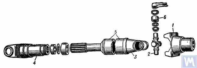
Figure 5. Universal joint drive: 1 — flange for securing the driveshaft; 2 — universal joint cross; 3 — universal joint yoke; 4 — sliding yoke; 5 — driveshaft tube; 6 — needle roller bearing with closed end
The universal joint drive consists of two universal joints with needle bearings, connected by a hollow shaft, and a sliding yoke with involute splines. To ensure reliable protection from dirt and provide good lubrication of the splined connection, the sliding yoke (6), connected to the secondary shaft (2) of the gearbox, is placed in an extension (1) attached to the gearbox housing. Additionally, this location of the splined connection (outside the zone between the joints) significantly increases the stiffness of the universal joint drive and reduces the likelihood of shaft vibrations when the sliding splined connection wears out.
میل گاردان از یک لوله نازک دیواره جوش داده شده با برق (8) ساخته شده است که دو یوغ یکسان (9) در هر انتها به صورت پرسی در آن قرار گرفته و سپس با جوش قوسی جوش داده میشوند. محفظههای یاتاقان سوزنی (18) صلیب (25) به صورت پرسی در سوراخهای یوغ (9) قرار گرفته و با حلقههای نگهدارنده فنر (20) محکم شدهاند. هر یاتاقان با مفصل یونیورسال شامل 22 سوزن (21) است. درپوشهای مهر و موم شده (24) به صورت پرسی بر روی سرستونهای بیرون زده صلیبها قرار میگیرند که حلقههای چوب پنبهای (23) در آنها نصب شدهاند. یاتاقانها با استفاده از یک اتصال گریس زاویهدار (17) که به یک سوراخ رزوهدار در مرکز صلیب پیچ شده و به کانالهای درون سرستونهای صلیب متصل است، روغنکاری میشوند. در طرف مقابل صلیب اتصال جهانی، یک شیر اطمینان (16) در مرکز آن قرار دارد که برای تخلیه گریس اضافی هنگام پر کردن صلیب و یاتاقانها و جلوگیری از افزایش فشار داخل صلیب در حین کار طراحی شده است (شیر با فشار حدود 3.5 کیلوگرم بر سانتیمتر مربع فعال میشود). ضرورت تعبیه شیر اطمینان به این دلیل است که افزایش بیش از حد فشار در داخل صلیب میتواند منجر به آسیب (بیرون زدگی) آببندیهای چوب پنبهای شود.
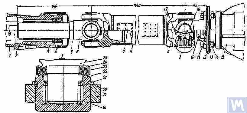
Figure 6. Driveshaft Assembly: 1 — gearbox extension; 2 — secondary shaft of the gearbox; 3 and 5 — dirt deflectors; 4 — rubber seals; 6 — sliding yoke; 7 — balancing plate; 8 — driveshaft tube; 9 — yoke; 10 — flange yoke; 11 — bolt; 12 — flange of the rear axle drive gear; 13 — spring washer; 14 — nut; 15 — rear axle; 16 — safety valve; 17 — angular grease fitting; 18 — needle bearing; 19 — yoke eye; 20 — spring retaining ring; 21 — needle; 22 — washer with toroidal end; 23 — cork ring; 24 — stamped cap; 25 — cross
میل گاردان، که با هر دو مفصل یونیورسال مونتاژ شده است، با جوش دادن صفحات متعادل کننده (7) به لوله، در هر دو انتها به دقت به صورت دینامیکی متعادل میشود. بنابراین، هنگام جداسازی شفت، تمام قطعات آن باید به دقت علامت گذاری شوند تا بتوان آنها را در موقعیتهای اصلی خود دوباره مونتاژ کرد. عدم رعایت این دستورالعمل، تعادل شفت را مختل میکند و باعث لرزشهایی میشود که میتواند به گیربکس و بدنه خودرو آسیب برساند. اگر قطعات جداگانه فرسوده شوند، به خصوص اگر لوله به دلیل ضربه خم شود و متعادل کردن دینامیکی شفت پس از مونتاژ غیرممکن شود، کل شفت باید تعویض شود.
Possible Driveshaft Malfunctions, Their Causes, and Solutions
| Cause of Malfunction | Solution |
|---|---|
| Driveshaft Vibration | |
| 1. Shaft bending due to an obstacle | 1. Straighten and dynamically balance the assembled shaft or replace the assembled shaft |
| 2. Bearing and cross wear | 2. Replace bearings and crosses and dynamically balance the assembled shaft |
| 3. Wear of extension bushings and sliding yoke | 3. Replace the extension and sliding yoke and dynamically balance the assembled shaft |
| Knocks When Starting and Coasting | |
| 1. Wear of sliding yoke splines or secondary gearbox shaft | 1. Replace worn parts. When replacing the sliding yoke, dynamically balance the assembled shaft |
| 2. Loose bolts securing the flange yoke to the rear axle drive gear flange | 2. Tighten bolts |
| Oil Throwing from Universal Joint Seals | |
| Wear of cork rings in universal joint seals | Replace cork rings, maintaining the relative position of all driveshaft parts during reassembly. If there is wear on crosses and bearings, replace the bearings and crosses and dynamically balance the assembled shaft |
3. Driveshaft Balancing
After repairing and assembling the driveshaft, it is dynamically balanced on a machine. One design of a balancing machine is shown in Figure 7. The machine consists of a plate (18), a pendulum frame (8) mounted on four vertical elastic rods (3), ensuring its oscillation in the horizontal plane. A bracket and front headstock (9), secured on a bracket (4), are mounted on the longitudinal tubes of the pendulum frame (8). The rear headstock (6) is on a movable traverse (5), allowing dynamic balancing of driveshafts of different lengths. The headstock spindles are mounted on precision ball bearings. The spindle of the front headstock (9) is driven by an electric motor installed in the machine base, through a V-belt drive and an intermediate shaft, on which a limb (10) (graduated disk) is mounted. Additionally, two stands (15) with retractable locking pins (17) are installed on the machine plate (18), ensuring the fixation of the front and rear ends of the pendulum frame depending on the balancing of the front or rear end of the driveshaft.
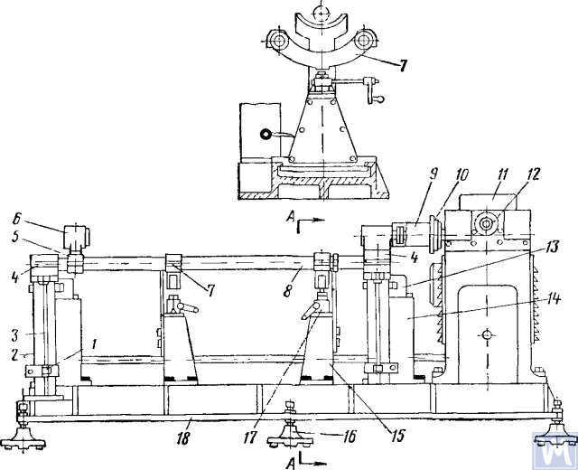
Figure 7. Dynamic Balancing Machine for Driveshafts
1—clamp; 2—dampers; 3—elastic rod; 4—bracket; 5—movable traverse; 6—rear headstock; 7—crossbar; 8—pendulum frame; 9—front driving headstock; 10—limb-disk; 11—millivoltmeter; 12—limb of the commutator-rectifier shaft; 13—magnetoelectric sensor; 14—fixed stand; 15—fixator stand; 16—support; 17—fixator; 18—support plate
The fixed stands (14) are mounted at the rear of the machine plate, and magnetoelectric sensors (13) are installed on them, with rods connected to the ends of the pendulum frame. To prevent resonance vibrations of the frame, dampers (2) filled with oil are installed under the brackets (4).
در طول بالانس دینامیکی، مجموعه میل گاردان به همراه یوک کشویی روی دستگاه نصب و محکم میشود. یک سر میل گاردان توسط یک یوک فلنجی به فلنج سرسیلندر جلویی و سر دیگر توسط گردنه نگهدارنده یوک کشویی به غلاف خاردار سرسیلندر عقب متصل میشود. سپس سهولت چرخش میل گاردان بررسی میشود و یک سر قاب پاندول دستگاه با استفاده از فیکساتور ثابت میشود. پس از روشن کردن دستگاه، شاخه یکسوکننده در خلاف جهت عقربههای ساعت چرخانده میشود و سوزن میلیولتمتر را به حداکثر مقدار خود میرساند. مقدار میلیولتمتر با مقدار عدم تعادل مطابقت دارد. مقیاس میلیولتمتر بر حسب گرم-سانتیمتر یا گرم وزنه تعادل درجهبندی شده است. با ادامه چرخش شاخه یکسوکننده در خلاف جهت عقربههای ساعت، مقدار میلیولتمتر به صفر میرسد و دستگاه متوقف میشود. بر اساس مقدار شاخه یکسوکننده، جابجایی زاویهای (زاویه جابجایی عدم تعادل) تعیین میشود و با چرخاندن دستی میل گاردان، این مقدار روی شاخه شفت میانی تنظیم میشود. محل جوش صفحه تعادل در بالای محور محرک و قسمت وزنهدار در پایین صفحه اصلاح خواهد بود. سپس صفحه تعادل با سیم نازک در فاصله 10 میلیمتر از جوش متصل و بسته میشود، دستگاه روشن میشود و تعادل انتهای محور محرک با صفحه بررسی میشود. عدم تعادل نباید بیش از 70 گرم بر سانتیمتر باشد. سپس، با آزاد کردن یک سر و محکم کردن سر دیگر قاب آونگ با پایه ثابتکننده، تعادل دینامیکی انتهای دیگر محور محرک طبق توالی تکنولوژیکی که در بالا توضیح داده شد، انجام میشود.
Driveshafts have some balancing features. For most parts, the base for dynamic balancing is the support necks (e.g., rotors of electric motors, turbines, spindles, crankshafts, etc.), but for driveshafts, it is the flanges. During assembly, there are unavoidable gaps in different connections leading to imbalance. If the minimum imbalance cannot be achieved during balancing, the shaft is rejected. The accuracy of balancing is influenced by the following factors:
- Gap in the connection between the landing belt of the driveshaft flange and the inner hole of the clamping flange of the left and right support headstocks;
- Radial and end runout of the base surfaces of the flange;
- شکاف در اتصالات لولا و خاردار. وجود گریس در حفره اتصال خاردار میتواند منجر به عدم تعادل "شناور" شود. اگر این امر مانع از دستیابی به دقت بالانس مورد نیاز شود، محور محرک بدون گریس بالانس میشود.
Some imbalances may be completely uncorrectable. If increased friction is observed in the universal joints of the driveshaft, the mutual influence of the correction planes increases. This leads to a decrease in the performance and accuracy of balancing.
طبق OST 37.001.053-74، استانداردهای عدم تعادل زیر تعیین شدهاند: میللنگهای محرک با دو مفصل (دو تکیهگاه) به صورت دینامیکی بالانس میشوند و با سه مفصل (سه تکیهگاه) - با تکیهگاه میانی مونتاژ میشوند؛ فلنجها (یوکها) میللنگهای محرک و کوپلینگهایی که وزن آنها بیش از 5 کیلوگرم است، قبل از مونتاژ شفت یا کوپلینگ به صورت استاتیکی بالانس میشوند؛ هنجارهای عدم تعادل باقیمانده برای میللنگهای محرک در هر انتها یا در تکیهگاه میانی میللنگهای محرک سه مفصلی با عدم تعادل خاص ارزیابی میشوند؛
حداکثر مقدار مجاز ویژه عدم تعادل باقیمانده در هر انتهای شفت یا در تکیهگاه میانی، و همچنین برای میللنگهای محرک سه مفصلی در هر موقعیتی روی پایه تعادل، نباید از مقادیر زیر تجاوز کند: برای گیربکسهای خودروهای سواری و کامیونهای کوچک (تا 1 تن) و اتوبوسهای بسیار کوچک - 6 گرم بر سانتیمتر مربع بر کیلوگرم، برای بقیه - 10 گرم بر سانتیمتر مربع بر کیلوگرم. حداکثر مقدار مجاز عدم تعادل باقیمانده میللنگ یا میللنگ محرک سه مفصلی باید روی پایه تعادل با فرکانس چرخشی مطابق با فرکانسهای آنها در گیربکس در حداکثر سرعت خودرو تضمین شود.
برای میل گاردانها و میل گاردانهای سه مفصلی کامیونهایی با ظرفیت بار ۴ تن و بالاتر، اتوبوسهای کوچک و بزرگ، کاهش فرکانس چرخش روی پایه تعادل به ۷۰۱TP3T فرکانس چرخش شفتهای گیربکس در حداکثر سرعت خودرو مجاز است. طبق OST 37.001.053-74، فرکانس چرخش متعادل کننده میل گاردانها باید برابر باشد با:
nb = (0.7 ... 1.0) نr,
where nb – فرکانس چرخش متعادل (باید با مشخصات فنی اصلی پایه مطابقت داشته باشد، n=3000 دقیقه-1; nr - حداکثر فرکانس چرخش کاری، حداقل-1.
In practice, due to the gap in the joints and splined connections, the driveshaft cannot be balanced at the recommended rotation frequency. In this case, another rotation frequency is chosen, at which it balances.
4. Modern Balancing Machines for Driveshafts
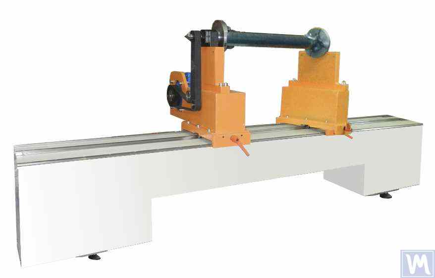
Figure 8. Balancing Machine for Driveshafts up to 2 Meters Long, Weighing up to 500 kg
The model has 2 stands and allows balancing in 2 correction planes.
Balancing Machine for Driveshafts up to 4200 mm Long, Weighing up to 400 kg
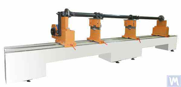
Figure 9. Balancing Machine for Driveshafts up to 4200 mm Long, Weighing up to 400 kg
The model has 4 stands and allows balancing in 4 correction planes simultaneously.
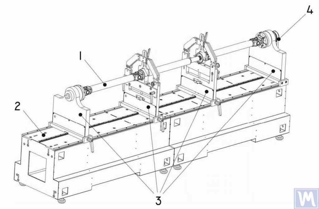
Figure 10. Horizontal Hard Bearing Balancing Machine for Dynamic Balancing of Driveshafts
1 – Balancing item (driveshaft); 2 – Machine base; 3 – Machine supports; 4 – Machine drive; The structural elements of the machine supports are shown in Figure 9.
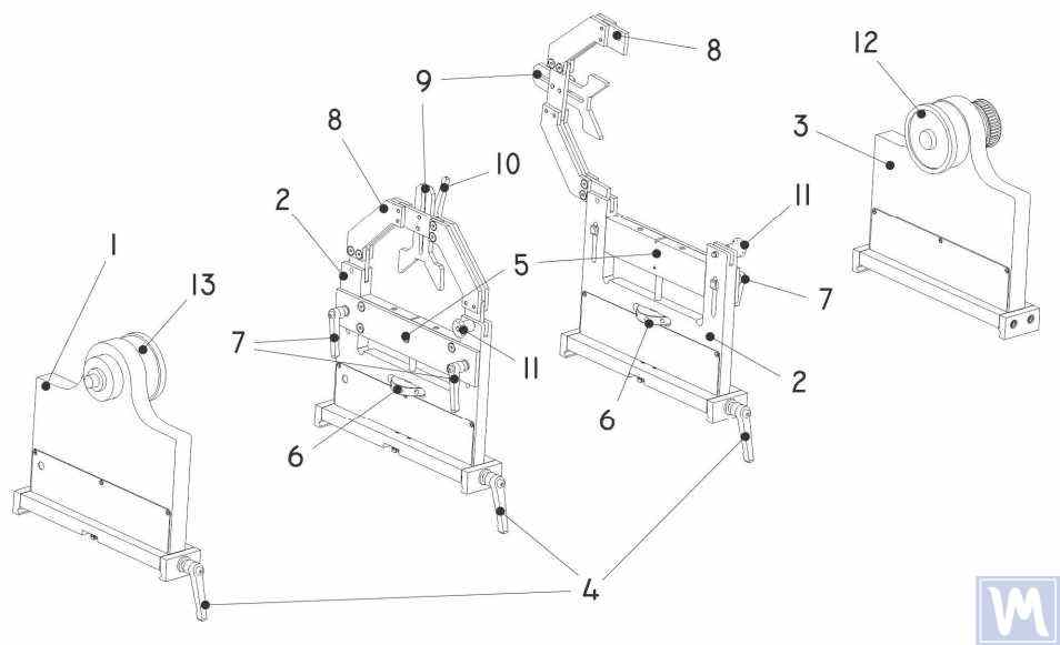
Figure 11. Machine Support Elements for Dynamic Balancing of Driveshafts
1 – Left non-adjustable support; 2 – Intermediate adjustable support (2 pcs.); 3 – Right non-adjustable fixed support; 4 – Support frame lock handle; 5 – Movable support platform; 6 – Support vertical adjustment nut; 7 – Vertical position lock handles; 8 – Support clamping bracket; 9 – Intermediate bearing movable clamp; 10 – Clamp lock handle; 11 – Clamping bracket lock; 12 – Drive (leading) spindle for item installation; 13 – Driven spindle
5. Preparation for Driveshaft Balancing
Below, we will consider the setup of the machine supports and the installation of the balancing item (four-support driveshaft) on the machine supports.
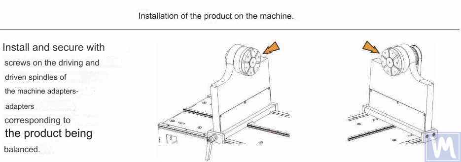
Figure 12. Installation of Transitional Flanges on the Spindles of the Balancing Machine
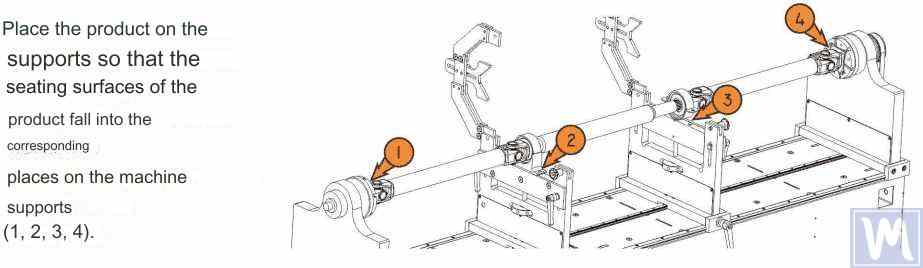
Figure 13. Installation of the Driveshaft on the Supports of the Balancing Machine
Figure 14. Leveling the Driveshaft Horizontally on the Supports of the Balancing Machine Using a Bubble Level
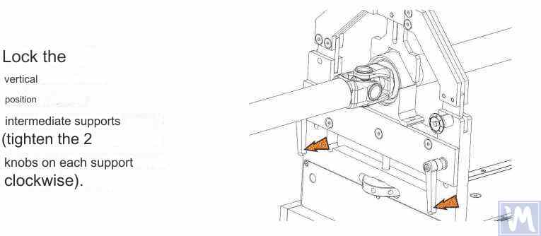
Figure 15. Fixing the Intermediate Supports of the Balancing Machine to Prevent Vertical Displacement of the Driveshaft
Rotate the item manually for a full turn. Ensure that it rotates freely and without jamming on the supports. After this, the mechanical part of the machine is set up, and the item installation is complete.
6. Driveshaft Balancing Procedure
The process of driveshaft balancing on the balancing machine will be considered using the Balanset-4 measuring system as an example. The Balanset-4 is a portable balancing kit designed for balancing in one, two, three, and four correction planes of rotors, either rotating in their own bearings or mounted on a balancing machine. The device includes up to four vibration sensors, a phase angle sensor, a four-channel measuring unit, and a portable computer.
The entire balancing process, including measurement, processing, and display of information on the magnitude and location of corrective weights, is performed automatically and does not require the user to have additional skills and knowledge beyond the provided instructions. The results of all balancing operations are saved in the Balancing Archive and can be printed as reports if necessary. In addition to balancing, the Balanset-4 can also be used as a regular vibro-tachometer, allowing measurement on four channels of the root mean square (RMS) value of total vibration, RMS of the rotational component of vibration, and control of rotor rotation frequency.
Furthermore, the device allows displaying graphs of the time function and vibration spectrum by vibration velocity, which can be useful in assessing the technical condition of the balanced machine.
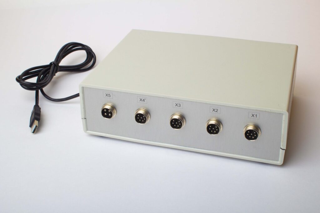
Figure 16. External View of the Balanset-4 Device for Use as a Measuring and Computing System of the Driveshaft Balancing Machine
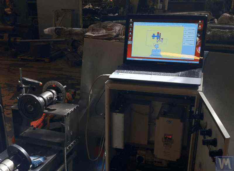
Figure 17. Example of Using the Balanset-4 Device as a Measuring and Computing System of the Driveshaft Balancing Machine
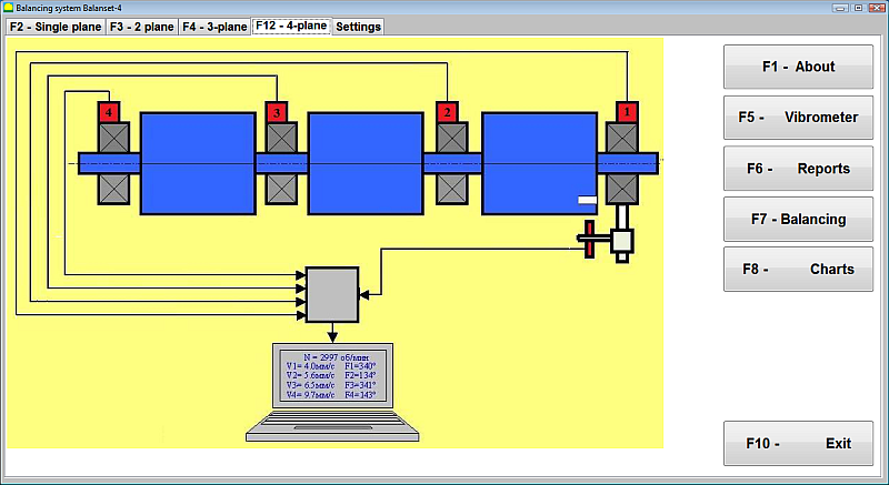
Figure 18. User Interface of the Balanset-4 Device
دستگاه Balanset-4 میتواند به دو نوع حسگر مجهز شود - شتابسنجهای ارتعاشی برای اندازهگیری ارتعاش (شتاب ارتعاش) و حسگرهای نیرو. حسگرهای ارتعاشی برای کار در ماشینهای بالانس نوع پسرزونانسی استفاده میشوند، در حالی که حسگرهای نیرو برای ماشینهای بالانس نوع پیشرزونانسی استفاده میشوند.
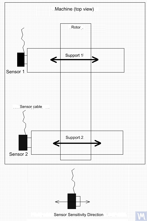
Figure 19. Installation of Balanset-4 Vibration Sensors on the Supports of the Balancing Machine
جهت محور حساسیت سنسورها باید با جهت جابجایی ارتعاش تکیهگاه، در این مورد - افقی - مطابقت داشته باشد. برای اطلاعات بیشتر در مورد نصب سنسور، به بخش «بالانس روتورها در شرایط عملیاتی» مراجعه کنید. نصب سنسورهای نیرو به ویژگیهای طراحی دستگاه بستگی دارد.
- Install vibration sensors 1, 2, 3, 4 on the supports of the balancing machine.
- Connect the vibration sensors to connectors X1, X2, X3, X4.
- Install the phase angle sensor (laser tachometer) 5 so that the nominal gap between the radial (or end) surface of the balanced rotor and the sensor housing is in the range of 10 to 300 mm.
- Attach a reflective tape mark with a width of at least 10-15 mm to the rotor surface.
- Connect the phase angle sensor to connector X5.
- Connect the measuring unit to the computer’s USB port.
- When using mains power, connect the computer to the power supply unit.
- Connect the power supply unit to a 220 V, 50 Hz network.
- Turn on the computer and select the “BalCom-4” program.
- Press the “F12-four-plane” button (or the F12 function key on the computer keyboard) to select the mode for measuring vibration simultaneously in four planes using vibration sensors 1, 2, 3, 4, connected respectively to inputs X1, X2, X3, and X4 of the measuring unit.
- A mnemonic diagram illustrating the process of measuring vibration simultaneously on four measurement channels (or the process of balancing in four planes) appears on the computer display, as shown in Figure 16.
Before performing balancing, it is recommended to take measurements in the vibrometer mode (F5 button).
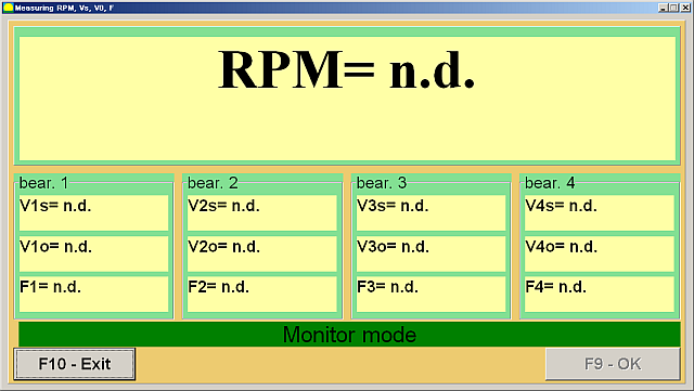
Figure 20. Vibrometer Mode Measurements
اگر مقدار کل ارتعاش V1s (V2s) تقریباً با مقدار مولفه چرخشی V1o (V2o) مطابقت داشته باشد، میتوان فرض کرد که سهم اصلی در ارتعاش مکانیزم به دلیل عدم تعادل روتور است. اگر مقدار کل ارتعاش V1s (V2s) به طور قابل توجهی از مولفه چرخشی V1o (V2o) بیشتر باشد، توصیه میشود مکانیزم بررسی شود - وضعیت یاتاقانها بررسی شود، از نصب ایمن روی فونداسیون اطمینان حاصل شود، تأیید شود که روتور در حین چرخش با قطعات ثابت تماس نداشته باشد و تأثیر ارتعاشات سایر مکانیزمها و غیره در نظر گرفته شود.
مطالعه نمودارهای تابع زمان و طیفهای ارتعاشی بهدستآمده در حالت «نمودارها-تحلیل طیفی» میتواند در اینجا مفید باشد.
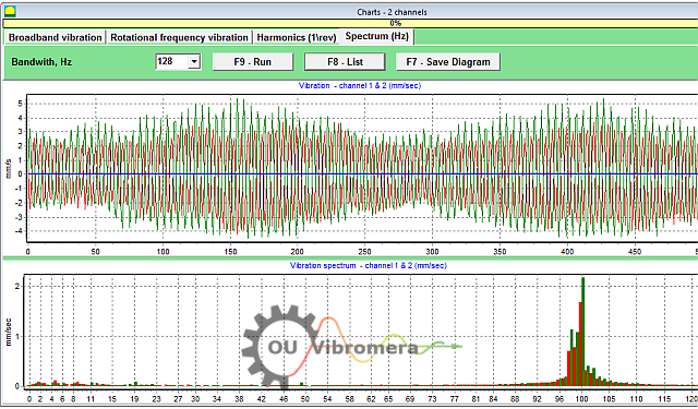
Figure 21. Vibration Time Function and Spectrum Graphs
نمودار نشان میدهد که در کدام فرکانسها، سطح ارتعاش بالاترین است. اگر این فرکانسها با فرکانس چرخش روتور مکانیزم متعادل متفاوت باشند، لازم است منابع این اجزای ارتعاش شناسایی شده و قبل از متعادلسازی، اقداماتی برای از بین بردن آنها انجام شود.
It is also important to pay attention to the stability of the readings in vibrometer mode – the amplitude and phase of the vibration should not change by more than 10-15% during measurement. Otherwise, the mechanism might be operating near a resonance region. In this case, the rotor speed should be adjusted.
هنگام انجام بالانس چهار صفحهای در حالت "اولیه"، پنج بار کالیبراسیون و حداقل یک بار تأیید دستگاه بالانس شده مورد نیاز است. اندازهگیری ارتعاش در طول اولین بار بالانس دستگاه بدون وزنه آزمایشی در فضای کاری "بالانس چهار صفحهای" انجام میشود. اجراهای بعدی با یک وزنه آزمایشی که به ترتیب روی محور محرک در هر صفحه اصلاح (در ناحیه هر تکیهگاه دستگاه بالانس) نصب شده است، انجام میشود.
Before each subsequent run, the following steps should be taken:
- چرخش روتور دستگاه متعادل را متوقف کنید.
- Remove the previously installed trial weight.
- Install the trial weight in the next plane.
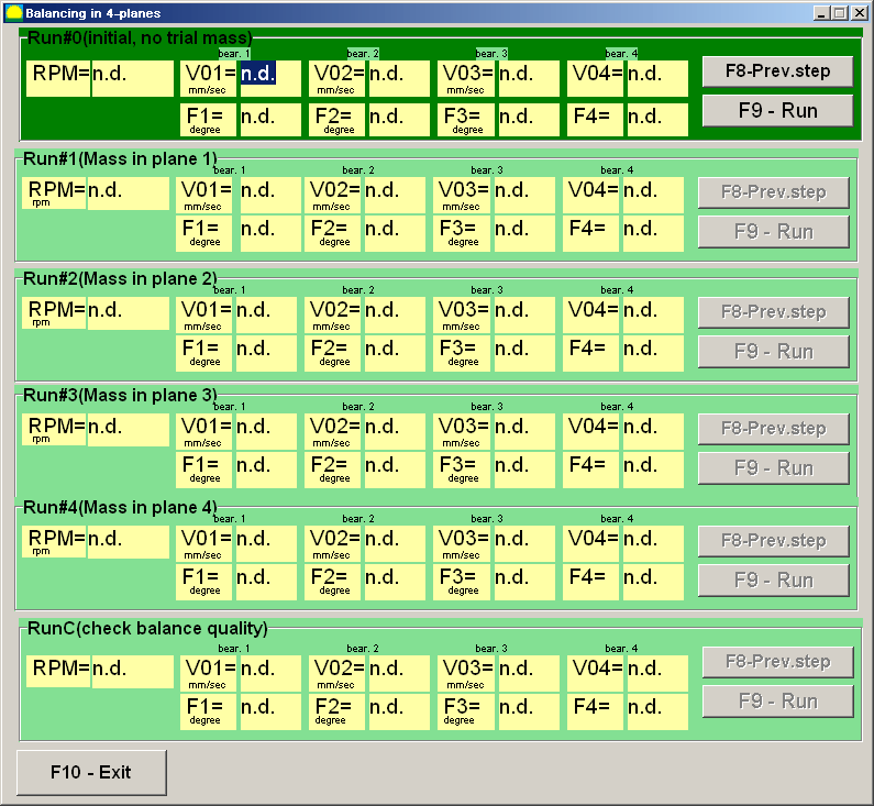
Figure 23. Four-Plane Balancing Workspace
پس از تکمیل هر اندازهگیری، نتایج فرکانس چرخش روتور (N)ob), as well as the RMS values (Vo1, Vo2, Vo3, Vo4) and the phases (F1, F2, F3, F4) ارتعاش در فرکانس چرخشی روتور متعادل در فیلدهای مربوطه در پنجره برنامه ذخیره میشوند. پس از پنجمین اجرا (وزن در صفحه ۴)، فضای کاری "وزنههای متعادل" (شکل ۲۴ را ببینید) ظاهر میشود و مقادیر محاسبهشده جرمها (M) را نمایش میدهد.1, M2, M3, M4) and the installation angles (f1, f2, f3, f4) of the corrective weights that need to be installed on the rotor in four planes to compensate for its imbalance.
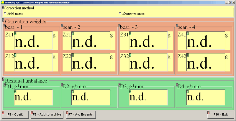
Figure 24. Workspace with Calculated Parameters of Corrective Weights in Four Planes
Attention! پس از تکمیل فرآیند اندازهگیری در طول پنجمین اجرای دستگاه متوازن، لازم است چرخش روتور متوقف شده و وزنه آزمایشی نصب شده قبلی برداشته شود. تنها پس از این کار میتوانید وزنههای اصلاحی را روی روتور نصب (یا بردارید) کنید.
موقعیت زاویهای برای اضافه کردن (یا برداشتن) وزنه اصلاحی روی روتور در سیستم مختصات قطبی از محل نصب وزنه آزمایشی اندازهگیری میشود. جهت اندازهگیری زاویه با جهت چرخش روتور مطابقت دارد. در صورت بالانس شدن توسط پرهها، پره روتور بالانس شده که به طور مشروط به عنوان پره اول در نظر گرفته میشود، با محل نصب وزنه آزمایشی مطابقت دارد. جهت شمارهگذاری پرهها که روی صفحه نمایش کامپیوتر نشان داده شده است، از جهت چرخش روتور پیروی میکند.
در این نسخه از برنامه، به طور پیشفرض فرض میشود که وزنه اصلاحی به روتور اضافه خواهد شد. این موضوع با علامت تعیین شده در فیلد "افزودن" نشان داده شده است. اگر اصلاح عدم تعادل با حذف وزنه (مثلاً با سوراخ کردن) ضروری باشد، علامت را با استفاده از ماوس در فیلد "حذف" تنظیم کنید، پس از آن موقعیت زاویهای وزنه اصلاحی به طور خودکار ۱۸۰ درجه تغییر خواهد کرد.
پس از نصب وزنههای اصلاحی روی روتور متعادل، دکمه "خروج - F10" (یا کلید تابع F10 روی صفحه کلید کامپیوتر) را فشار دهید تا به فضای کاری قبلی "متعادلسازی چهار صفحهای" برگردید و اثربخشی عملیات متعادلسازی را بررسی کنید. پس از تکمیل اجرای تأیید، نتایج فرکانس چرخش روتور (N)ob) and the RMS values (Vo1, Vo2, Vo3, Vo4) and phases (F1, F2, F3, F4) ارتعاش در فرکانس چرخشی روتور متعادل ذخیره میشوند. همزمان، فضای کاری "وزنههای متعادلکننده" (به شکل 21 مراجعه کنید) روی فضای کاری "متعادلکننده چهار صفحهای" ظاهر میشود و پارامترهای محاسبهشده وزنههای اصلاحی اضافی را که باید روی روتور نصب (یا برداشته) شوند تا عدم تعادل باقیمانده آن جبران شود، نمایش میدهد. علاوه بر این، این فضای کاری مقادیر عدم تعادل باقیمانده حاصل شده پس از متعادلسازی را نشان میدهد. اگر مقادیر ارتعاش باقیمانده و/یا عدم تعادل باقیمانده روتور متعادل، الزامات تلرانس مشخص شده در مستندات فنی را برآورده کنند، فرآیند متعادلسازی میتواند تکمیل شود. در غیر این صورت، فرآیند متعادلسازی میتواند ادامه یابد. این روش امکان اصلاح خطاهای احتمالی را از طریق تقریبهای متوالی که ممکن است هنگام نصب (برداشتن) وزنه اصلاحی روی روتور متعادل رخ دهد، فراهم میکند.
اگر فرآیند بالانس ادامه یابد، وزنههای اصلاحی اضافی باید طبق پارامترهای مشخص شده در فضای کاری «وزنههای بالانس»، روی روتور بالانس شده نصب (یا برداشته) شوند.
دکمه "ضرایب - F8" (یا کلید تابع F8 روی صفحه کلید کامپیوتر) برای مشاهده و ذخیره ضرایب بالانس روتور (ضرایب تأثیر دینامیکی) محاسبه شده از نتایج پنج بار کالیبراسیون در حافظه کامپیوتر استفاده میشود.
7. Recommended Balancing Accuracy Classes for Rigid Rotors
Table 2. Recommended Balancing Accuracy Classes for Rigid Rotors.

Recommended Balancing Accuracy Classes for Rigid Rotors
| Types of Machines (Rotors) | Balancing Accuracy Class | Value eper Ω mm/s |
|---|---|---|
| Drive crankshafts (structurally unbalanced) for large low-speed marine diesel engines (piston speed less than 9 m/s) | G 4000 | 4000 |
| Drive crankshafts (structurally balanced) for large low-speed marine diesel engines (piston speed less than 9 m/s) | G 1600 | 1600 |
| Drive crankshafts (structurally unbalanced) on vibration isolators | G 630 | 630 |
| Drive crankshafts (structurally unbalanced) on rigid supports | G 250 | 250 |
| Reciprocating engines assembled for passenger cars, trucks, and locomotives | G 100 | 100 |
| Automobile parts: wheels, wheel rims, wheelsets, transmissions | ||
| Drive crankshafts (structurally balanced) on vibration isolators | G 40 | 40 |
| Agricultural machines | G 16 | 16 |
| Drive crankshafts (balanced) on rigid supports | ||
| Crushers | ||
| Drive shafts (driveshafts, screw shafts) | ||
| Aircraft gas turbines | G 6.3 | 6.3 |
| Centrifuges (separators, settlers) | ||
| Electric motors and generators (with a shaft height of at least 80 mm) with a maximum nominal rotation speed of up to 950 min-1 | ||
| Electric motors with a shaft height of less than 80 mm | ||
| Fans | ||
| Gear drives | ||
| General-purpose machines | ||
| Metal cutting machines | ||
| Papermaking machines | ||
| Pumps | ||
| Turbochargers | ||
| Water turbines | ||
| Compressors | ||
| Computer-controlled drives | G 2.5 | 2.5 |
| Electric motors and generators (with a shaft height of at least 80 mm) with a maximum nominal rotation speed over 950 min-1 | ||
| Gas and steam turbines | ||
| Metal cutting machine drives | ||
| Textile machines | ||
| Audio and video equipment drives | G 1 | 1 |
| Grinding machine drives | ||
| Spindles and drives of high-precision equipment | G 0.4 | 0.4 |
سوالات متداول در مورد بالانس کردن میل گاردان
بالانس کردن میل گاردان چیست؟
بالانس کردن میل گاردان فرآیندی است که در آن هرگونه عدم تعادل جرمی در میل گاردان اصلاح میشود تا بدون ایجاد لرزش، به نرمی بچرخد. این کار شامل اندازهگیری محل سنگینتر بودن میل گاردان در یک طرف و سپس اضافه یا کم کردن مقادیر کمی وزن (به عنوان مثال، جوشکاری روی وزنههای تعادل) برای خنثی کردن آن عدم تعادل است. یک میل گاردان متعادل به طور یکنواخت کار میکند که از لرزش بیش از حد و سایش قطعات خودرو جلوگیری میکند.
چرا بالانس کردن میل گاردان مهم است؟
یک میل گاردان نامتعادل میتواند منجر به ارتعاشات شدید، به خصوص در سرعتهای خاص، شود و ممکن است باعث ایجاد صداهای تقتق در هنگام شتابگیری یا تعویض دنده شود. با گذشت زمان، این ارتعاشات میتوانند به یاتاقانها، اتصالات یونیورسال و سایر اجزای سیستم انتقال قدرت آسیب برسانند. بالانس کردن میل گاردان این ارتعاشات را از بین میبرد، رانندگی نرمتری را تضمین میکند، فشار روی قطعات را کاهش میدهد و از آسیبهای پرهزینه یا خرابی جلوگیری میکند.
علائم رایج عدم تعادل میل گاردان چیست؟
علائم معمول یک میل گاردان نامتعادل یا معیوب شامل لرزش یا تکانهای قابل توجه در کف یا صندلی خودرو، به ویژه با افزایش سرعت است. همچنین ممکن است هنگام تعویض دنده یا در هنگام شتابگیری و کاهش سرعت، صدای ضربه یا تقتق بشنوید. در برخی موارد، مفصل یونیورسال ممکن است به دلیل عدم تعادل بیش از حد گرم شود. اگر این علائم را مشاهده کردید، احتمالاً میل گاردان نیاز به بالانس یا تعمیر دارد.
چگونه یک محور محرک را متعادل میکنید؟
بالانس کردن محور محرک معمولاً با استفاده از یک دستگاه بالانس مخصوص انجام میشود. محور محرک نصب شده و با سرعت بالا میچرخد در حالی که حسگرها هرگونه عدم تعادل را تشخیص میدهند. سپس یک تکنسین بر اساس دادههای دستگاه، وزنههای کوچکی را به محور محرک در موقعیتهای خاص متصل میکند (یا موادی را برمیدارد). این فرآیند تا زمانی که محور محرک بدون لرزش قابل توجهی بچرخد، تکرار میشود. سیستمهای مدرن مانند Balanset-4 میتوانند این فرآیند را هدایت کرده و دقیقاً محاسبه کنند که برای بالانس دقیق، کجا و چه مقدار وزن باید اضافه شود.
Conclusion
در نتیجه، بالانس صحیح محور محرک برای ایمنی، عملکرد و صرفهجویی در هزینه ضروری است. با تشخیص و اصلاح عدم تعادل، از سایش غیرضروری قطعات جلوگیری میکنید، از خرابیهای مخرب جلوگیری میکنید و عملکرد بهینه دستگاه را حفظ میکنید. سیستمهای متعادلسازی مدرن مانند دستگاههای Balanset-1 و Balanset-4 ما، فرآیند را کارآمد میکنند و حتی به کارگاههای کوچک نیز در دستیابی به نتایج حرفهای کمک میکنند.
اگر با لرزشهای مداوم میل گاردان مواجه هستید یا به یک راهحل بالانس قابل اعتماد نیاز دارید، در اقدام تردید نکنید. مراحل ذکر شده در این راهنما را به کار بگیرید یا برای کمک با متخصصان ما مشورت کنید. با رویکرد و تجهیزات مناسب، میتوانید اطمینان حاصل کنید که میل گاردان شما برای سالهای آینده روان و قابل اعتماد کار میکند. تماس با ما برای کسب اطلاعات بیشتر یا بررسی بهترین تجهیزات بالانس شفت درایو برای نیازهای شما.

۰ دیدگاه