Mulcher Rotor Balancing: Stop the Vibration at Its Source
Your mulcher chews through trees and brush all day — and chews through bearings just as fast. The housing is cracked, the PTO shaft shudders, and the operator's hands go numb by lunch. The rotor is unbalanced. This guide shows you exactly how to fix it in the field, with real numbers from real jobs.



Why Mulchers Start Vibrating
A mulcher rotor spins at 1,500–2,400 RPM while smashing into wood, stone, soil, and buried metal. That's 25–40 revolutions per second, every one of them driving the teeth into abrasive, unpredictable material. Under those conditions, perfect balance doesn't last long. Here's what shifts the mass distribution:
- Broken or worn teeth. A single missing 100 g carbide tooth at 250 mm radius removes 25,000 g·mm of balanced mass — at 2,000 RPM that is roughly 110 kg of rotating centrifugal force, easily felt in the cab. Teeth wear unevenly depending on which side of the drum hits the material first.
- Impact damage. Hitting concrete, rebar, or large stones bends tooth holders and deforms the drum wall. Even if nothing visibly breaks, the mass distribution shifts.
- Debris buildup. Wet soil, sap, and wood fiber pack into the spaces between tooth holders. On a 1,200 mm drum, 200–400 grams of buildup is common after a few days in wet conditions.
- Weld repairs without re-balancing. Hard-facing (building up worn teeth with weld material) adds mass. Welding a new holder bracket adds mass. If you don't re-balance after, the repair itself creates imbalance.
- Manufacturing variance. No rotor leaves the factory perfectly balanced. Wall thickness, weld penetration, and bracket placement all vary within tolerance — but the tolerances add up.
What Breaks and What It Costs
At 2,000 RPM, centrifugal force from imbalance grows with the square of the speed. A 50-gram offset at 200 mm radius generates over 44 kg of cyclic force on the bearings — 33 times per second. That's a hammer blow every 30 milliseconds.
- Bearings — the direct casualty. Quality sets cost €80–€150. With severe vibration, operators replace them weekly. One contractor spent €400/week on bearings alone before balancing.
- Bearing housings — get wallowed oval from excess play. Once the seat is damaged, even new bearings won't run true. Housing repair: €200–€500.
- Housing and frame cracks — vibration fatigue cracks welds and base metal. You see reinforcement plates welded over previous reinforcement plates. Each repair weakens the structure.
- Hydraulic system — vibration loosens fittings and work-hardens seal surfaces. Fluid loss leads to pump cavitation and overheating. Hydraulic pump replacement: €2,000+.
- PTO shaft and tractor — vibration travels through the driveline into the tractor. U-joints, cab mounts, and hydraulic valve bodies all suffer.
- The operator — whole-body vibration exposure causes musculoskeletal injury. EU Directive 2002/44/EC sets action values at 0.5 m/s² — an unbalanced mulcher can exceed this easily.
ISO Vibration Standards
| G Grade | Application | Examples (ISO 21940-11, Table 1) |
|---|---|---|
| G40 | Coarse rotating parts | Car wheels, wheel rims, drive shafts |
| G16 | Agricultural machinery — mulchers belong here | Forestry & agricultural mulchers, crushing machines, cardan shafts |
| G6.3 | General machinery | Fans, pumps, gears, machine tools |
| G2.5 | Precision / high-speed drives | Compressors, gas and steam turbines, fast electric motors |
What G16 means in grams: permissible residual specific unbalance is eper = 9549 × G / n. For a 420 kg mulcher drum at 1,900 RPM that gives about 80 g·mm/kg — roughly 34,000 g·mm in total, or a residual weight of about 120 g at a 280 mm correction radius. The Balanset-1A software does this calculation for you.
| Zone | Rigid mounting (mm/s RMS) | Flexible mounting (mm/s RMS) | Meaning | Action |
|---|---|---|---|---|
| A | < 1.4 | < 2.3 | New-machine condition | None — excellent |
| B | 1.4 – 2.8 | 2.3 – 4.5 | Acceptable for unrestricted long-term operation | Monitor |
| C | 2.8 – 4.5 | 4.5 – 7.1 | Unsatisfactory for continuous operation | பராமரிப்பு திட்டமிடுங்கள் |
| D | > 4.5 | > 7.1 | Damage can occur | Stop. Fix now |
Bearing replacement: €80–€150 parts + 2–3 hours labour. If you're replacing weekly, that's €4,000–€7,500/year in parts alone, plus 100+ hours of wrench time instead of clearing land.
One day of contractor downtime during a clearing project: €800–€1,500 in lost revenue. Catastrophic rotor failure (cracked shaft): €2,000–€5,000 parts + weeks waiting.
The Balanset-1A is a one-time purchase (current price on the product page). In our field experience, two or three prevented bearing failures cover it — every job after that is pure savings.
Mulcher Types and Their Balancing Quirks
PTO Forestry Mulcher
Three-point hitch mounted, PTO-driven. Rotors 800–1,500 mm long with fixed carbide teeth. Imbalance from broken teeth and hard-facing repairs. Steady PTO speed makes balancing straightforward — hold the tractor throttle constant.
Excavator-Mounted Mulcher
Hydraulically driven, mounted on excavator arm. RPM varies with hydraulic flow — hold the dial steady during measurement. Heavier rotors (300–500 kg). Trial weights typically 40–100 g — size them with the 10% force rule from Step 1 below. Often requires two people for the balancing job.
Skid-Steer Mulcher
Compact but high-RPM. Sensitive to imbalance — even 20–30 g offset produces noticeable vibration. Lighter rotors need lighter trial weights (typically 10–30 g). Tight working space means creative sensor placement sometimes needed.
Drum-Type Land Clearing Mulcher
The heaviest category. Large-diameter drums with massive teeth for whole-tree grinding. Lower RPM but enormous centrifugal forces from sheer mass. Corrective weights can reach 300–500 g per plane. Allow extra time for these jobs.
Flail mowers and hammer-type mulchers behave much the same way — see our separate field report on dynamic balancing of flail mower and forestry mulcher rotors for another worked example.
Static vs Dynamic Imbalance: Why the Old Way Fails
The knife-edge method — rest the rotor on round bars, let the heavy side roll down, counterweight — is classic நிலைப்புட சமநிலையாக்கல். It works only for disc-shaped rotors whose length is less than about half their diameter (L/D below ~0.5). That covers brake discs and single pulleys, not mulcher drums.
A mulcher drum 1,200 mm long can have one heavy spot at the 12 o'clock position on the left end and another at 6 o'clock on the right end. On knife-edge supports, these cancel out — the rotor sits level. Spin it at 2,000 RPM and each heavy spot generates centrifugal force pulling outward in opposite directions. The result is a couple — a rocking force that's invisible when stationary but destructive when spinning.
எளிய விதி: If the rotor is longer than about half its diameter (L/D > 0.5), assume dynamic imbalance and use இரு-தளம் சமநிலையமைக்கல். Every mulcher drum falls into this category.
Why Shop Balancing Isn't Enough
Shops balance rotors on their own precision bearings. You reinstall the rotor — different bearing clearances, different housing alignment, different PTO runout. The "perfectly balanced" rotor vibrates again. Three reasons:
- Bearing fit tolerances. The shop machine has zero-clearance fixtures. Your bearings have working clearance and wear. The rotor spins on a different center.
- Assembly variables. Keyway alignment, coupling eccentricity, belt tension — all change when you reassemble. Just 0.1 mm of assembly eccentricity on a 400 kg rotor adds 40,000 g·mm of unbalance — more than the entire G16 allowance for that rotor at 1,900 RPM.
- Operating conditions. Thermal expansion under load, flail swing-out, PTO shaft alignment — the real-world environment differs from the shop bench.
In-situ balancing measures what the bearings actually experience under real conditions. That's why field results are typically better — and the rotor never leaves the machine.
Pre-Balancing Checklist
Balancing corrects mass distribution. It cannot fix broken hardware. Every minute of preparation saves ten minutes of troubleshooting.
- Clean the rotor. Remove caked soil, vegetation, sap — inside and outside the drum. 200 g of dried mud invalidates your readings.
- Inspect bearings. Grab the shaft near each bearing, check for radial and axial play. Grinding or clicking = replace first.
- Check every tooth and holder. All present? All tight? Damaged or heavily worn teeth — replace in diametrically opposite pairs.
- Look for cracks. Drum wall, end plates, mounting brackets, frame welds. A cracked drum flexes under centrifugal load — balancing readings will be erratic.
- Verify drive alignment. PTO shaft alignment or hydraulic motor coupling. Misalignment introduces vibration that isn't from imbalance.
- Tighten everything. Mounting bolts, three-point hitch, guards. Loose hardware = resonance problems.
- Lockout/Tagout the engine. Remove the key. Engage PTO brake.
- Eye protection when welding, grinding, and during all test runs.
- All personnel clear of the rotation plane during runs. A loose trial weight at 2,000 RPM is a projectile.
- Hearing protection — exposed mulcher drums exceed 95 dB easily.
- Never reach into the rotor area while PTO or hydraulics are engaged.
7-Step Field Balancing Procedure with Balanset-1A
The Balanset-1A uses the தாக்க குணகம் முறை. Three measurement runs, then permanent corrections. The software handles all the math.
Video: Mulcher Rotor Balancing Process
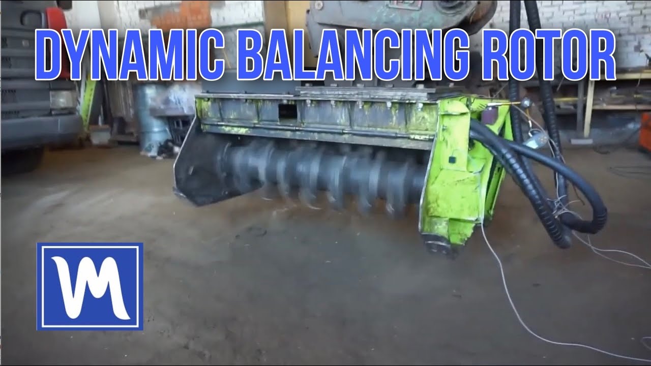
Pre-Inspection and Preparation
Complete the checklist above. Mark Plane 1 (drive-end bearing) and Plane 2 (free-end bearing). Size your trial weight with the 10% force rule: its centrifugal force should stay around a tenth of the rotor's weight — mtrial [kg] = 0.1 × M × g / (r × ω²). For a 420 kg drum at 1,900 RPM with a 250 mm mounting radius that works out to about 40 g. The goal: a clear 20–30% change in vibration amplitude or phase, without hammering the bearings.
Mount Sensors and Tachometer
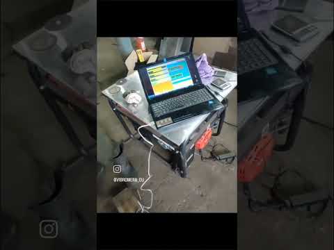
Vibration sensor 1 on bearing housing at Plane 1, sensor 2 at Plane 2. Magnetic bases, oriented perpendicular to the rotor axis. Clean the mounting surface — oil reduces magnetic hold. Reflective tape on the drum or pulley. Laser tachometer on magnetic stand, aimed at the tape.
Run 0 — Initial Vibration
Launch software, select இரு-தளம் சமநிரப்பு. Start the rotor at operating RPM. Wait 5–10 seconds for speed to stabilize. Record baseline vibration (mm/s) and phase at both sensors. These are your "before" numbers.
Run 1 — Trial Weight, Plane 1
Stop rotor. Enter trial weight mass and radius in software. Bolt trial weight to Plane 1. Note the angle from the reflective tape mark (direction of rotation). Run rotor, record. Stop. Remove the trial weight. Verify ≥20% change in amplitude or phase.
Run 2 — Trial Weight, Plane 2
Same trial weight at Plane 2. Mark angle. Run, record. Stop. Remove the trial weight. The software now has three data points and calculates the influence coefficients.
Install Permanent Corrections
Software displays the சரிசெய்யல் எடை mass and angle for each plane. Cut steel pieces to calculated weights (use a scale). Measure angles from the tape mark in the direction of rotation. Weld with good penetration — these weights take years of impacts.
Verify and Document
Final run. Target: Zone B or better — for a Group 2 machine on rigid mounting that means ≤ 2.8 mm/s, and below 1.4 mm/s is Zone A, new-machine condition (on flexible mounting the B/C boundary is 4.5 mm/s). If மீதமுள்ள ஏற்றத்தாழ்வு is still too high, run a trim balance. Save the report. Write the balance date and residual vibration on a label attached to the machine.
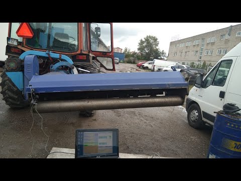
Field Report: Excavator-Mounted Mulcher, Southern Portugal
Machine: Hydraulic forestry mulcher on 25-ton excavator. Drum diameter 550 mm, length 1,300 mm, approximately 420 kg. 52 fixed carbide teeth. Operating at 1,900 RPM via hydraulic motor.
பிரச்சனை: Bearing replacements every 8–12 days for two months. Frame cracked at three mounting points — previously welded twice. Operator reporting hand numbness after 4-hour shifts. Contractor losing approximately €350/week in parts and downtime.
What we found: Three teeth broken (impact with buried granite boulder), one tooth holder bent 5°. After replacing teeth and straightening the holder, initial vibration: 14.6 mm/s at the drive end, 12.3 mm/s at the free end. Deep in Zone D.
Balancing: Two-plane dynamic balancing with Balanset-1A. Trial weight: 40 g bolt and nut, sized so its centrifugal force stayed near 10% of rotor weight. Corrections: 95 g at 128° on Plane 1, 130 g at 251° on Plane 2. Welded to drum end plates.
Result: Residual vibration: 1.8 mm/s drive end, 2.1 mm/s free end — from deep Zone D into Zone B, close to the 1.4 mm/s Zone A boundary. Total time including tooth replacement: 3 hours. Balancing alone: 50 minutes. Figures are from this specific job — results vary with rotor condition.





Troubleshooting: Still Vibrating After Balancing?
1. Mechanical Problems (Most Common)
- Worn bearings — even new cheap bearings can have excess clearance. Check for play after installation.
- Bent shaft — creates 1× RPM vibration that looks like imbalance but can't be corrected with weights. Check runout with a dial indicator: more than 0.05 mm TIR is a problem.
- Debris inside the drum — dirt or gravel trapped in a hollow drum shifts during rotation. Erratic, non-repeatable readings = clean the inside.
- Cracked frame — changes stiffness and creates resonance. Press on the frame and listen for tone changes in vibration.
2. Conditions During Balancing
- Resonance — operating RPM near a structural natural frequency amplifies even small imbalance. Try ±10% RPM if possible.
- RPM fluctuation — hydraulic drives are prone to this. Hold the flow control steady. >5% variation makes phase data unreliable.
- Something changed between runs — a sensor shifted, a tooth fell off, the excavator moved. Any change = restart from Run 0.
3. Procedure Errors
- சோதனை எடை மிகவும் இலகுவாக உள்ளது — less than 20% vibration change = calculation loses precision. Go heavier.
- Forgot to remove the trial weight — the #1 error. Verify it's off before welding corrections.
- Angle measured backward — must be from the tape mark in the direction of rotation. Counter-rotation puts the weight 180° off.
- Tachometer shifted — phase readings are wrong if the laser moved between runs. Secure it rigidly.
Balanset-1A: Key Specifications for Mulcher Work
Everything in this guide was done with the Balanset-1A — a two-channel portable balancer and vibration analyzer built for exactly this kind of field job. Mulcher rotors run 1,200–2,800 RPM, comfortably inside its working range.
| Parameter | Value |
|---|---|
| Channels / sensors | 2 vibration sensors + 1 laser tachometer |
| Balancing planes | 1 or 2 |
| அதிர்வन வேக வரம்பு | 0.2 – 80 mm/s RMS |
| Frequency range (balancing & FFT) | 5 – 1,000 Hz (amplitude error ≤ 10% above 550 Hz) |
| Balancing speed range | ≈ 300 – 60,000 RPM |
| Tachometer range | 250 – 90,000 RPM |
| Tolerance calculation | ISO 21940-11 G-grades (formerly ISO 1940-1) |
| Power | USB, 5 V DC (from the laptop — no mains adapter) |
| Enclosure protection | IP54 |
| Reports | PDF export, job archive |
Complete kit: measurement unit, two vibration sensors, laser tachometer with magnetic stand, reflective tape, scales and software.
View the Balanset-1A →அடிக்கடி கேட்கப்படும் கேள்விகள்
Can I balance the rotor without removing it from the mulcher?
Yes — in-situ (on-site) balancing is the preferred method. Sensors go on the bearing housings, the rotor runs at operating RPM, and the Balanset-1A calculates corrections. Results are often better than shop balancing because the measurement reflects real bearing fit, housing alignment, and operating conditions. Most jobs take 45–90 minutes.
Which balance quality grade (ISO 21940-11) does a mulcher need?
Per ISO 21940-11 (formerly ISO 1940-1) Table 1, agricultural machinery — mulchers included — falls under grade G16. Some high-RPM skid-steer mulchers are built to the tighter G6.3. The Balanset-1A software calculates the exact permissible residual imbalance in grams based on your rotor mass and RPM — no manual table lookup needed.
How often should I re-balance?
After any mass change: tooth replacement, hard-facing, welding, impact damage. In aggressive forestry work (stone, buried debris), check balance every 100–200 operating hours. In lighter conditions, balance when vibration noticeably increases. Teeth break regularly in forestry — expect to re-balance after every significant tooth replacement.
Why does my mulcher vibrate after the shop balanced the rotor?
The shop balanced it on their precision bearings with their fixtures — not yours. Reinstallation introduces imbalance from different bearing clearances, housing wear, keyway fit, and PTO alignment. In-situ balancing after reinstallation typically reduces vibration further because it corrects for everything in your actual operating environment.
How much does mulcher balancing cost?
Professional balancing service: typically €300–€600 per job, more in remote areas. The Balanset-1A is a one-time purchase (current price on the product page) that handles unlimited jobs — it usually pays for itself within the first few self-service balancing operations. If you manage multiple mulchers or offer balancing as a side service, the ROI is immediate.
Do I need training to use the Balanset-1A?
No certification required. The software walks you through each step — mount sensors, run rotor, attach trial weight, run again, weld corrections. Most operators feel confident after 2–3 practice jobs. Vibromera provides video tutorials, a detailed manual, and direct technical support via WhatsApp.
Your Mulcher Doesn't Have to Shake
An unbalanced rotor is a ticking clock — every hour of operation grinds away at bearings, cracks welds, and damages the tractor. But it's a solvable problem. With preparation and a Balanset-1A, you can take a mulcher from 14.6 mm/s down to 1.8 mm/s — as in our field case above — in under an hour, in the field, without pulling the rotor.
The investment pays for itself in prevented breakdowns. The real payoff is the weeks of smooth operation that follow — no daily bearing swaps, no cracked frames, no numb hands.
Balance the rotor. Fix the root cause. Everything else follows.

