బ్యాలెన్సింగ్ సేవలు › పంపులు & ఇంపెల్లర్లు
పంప్ బ్యాలెన్సింగ్ — ఆపరేటింగ్ వేగంలో ఇన్-సిటు
సెంట్రిఫ్యూగల్ మరియు హైడ్రాలిక్ పంపులు తుప్పు, కావిటేషన్ లేదా స్కేల్ ఇంపెల్లర్ మాస్ను మారిన క్షణం vibration అభివృద్ధి చేస్తాయి. మేము పంప్ రోటర్లను బ్యాలెన్స్ చేస్తాము అక్కడే, నిర్వహణ వేగంతో — కేసింగ్ తొలగింపు అవసరం లేదు, పైప్లైన్ డిస్కనెక్ట్ అవసరం లేదు — బేరింగ్ వైఫల్యం మరియు సీల్ లీక్లకు మూల కారణాన్ని ఒకే ఆన్-సైట్ సెషన్లో తొలగిస్తుంది.
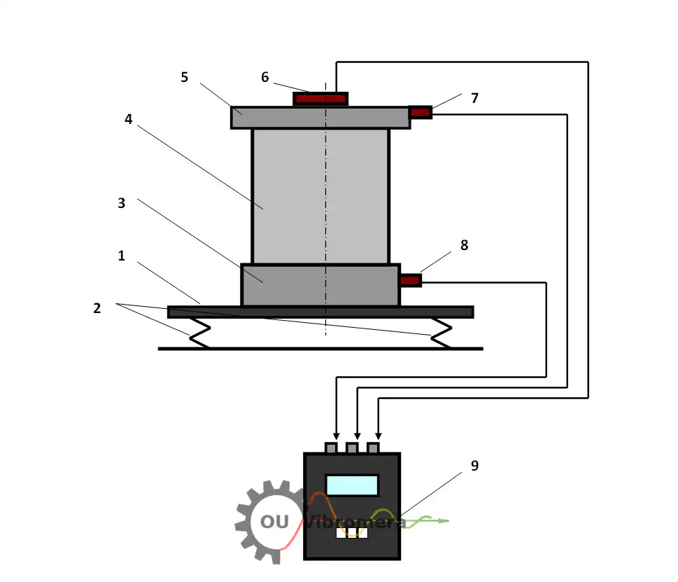
In short: పంప్ ఇంపెల్లర్ బ్యాలెన్సింగ్ ఇన్-సిటు పద్ధతిలో, సాధారణ ఆపరేటింగ్ వేగం మరియు ఒత్తిడిలో, ఇన్ఫ్లుయెన్స్-కోఎఫిషియంట్ మెథడ్ ఉపయోగించి నిర్వహించబడుతుంది. బేరింగ్ హౌజింగ్పై ఒక వైబ్రేషన్ సెన్సార్ మరియు షాఫ్ట్పై లేజర్ టాకోమీటర్ అన్బ్యాలెన్స్ స్థితిని కొలుస్తాయి; Balanset-1A ఖచ్చితమైన కరెక్షన్ మాస్ మరియు కోణాన్ని లెక్కిస్తుంది. పంప్ తొలగింపు అవసరం లేదు, పైప్ వర్క్ అవసరం లేదు — సాధారణ సింగిల్-స్టేజ్ పని ఒక గంటలోపు పూర్తవుతుంది, వైబ్రేషన్ను 70 % లేదా అంతకంటే ఎక్కువ తగ్గిస్తుంది మరియు బేరింగ్ మరియు సీల్ జీవితకాలాన్ని ఎనిమిది రెట్లు లేదా అంతకంటే ఎక్కువ పొడిగిస్తుంది.
మీ పంప్ అన్బ్యాలెన్స్లో ఉందని సూచనలు
పంప్ వైబ్రేషన్ను తరచుగా సాధారణంగా తోసిపుచ్చుతారు, అయినప్పటికీ ఈ లక్షణాలు ఇంపెల్లర్ లేదా రోటర్లో సరిచేయదగిన అన్బ్యాలెన్స్ను సూచిస్తాయి:
పంప్ ఇంపెల్లర్లు బ్యాలెన్స్ కోల్పోవడానికి కారణాలు — మరియు దాని ధర
కొత్తగా అసెంబుల్ చేయబడిన పంప్ ఫ్యాక్టరీలో బ్యాలెన్స్ చేయబడి వస్తుంది, కానీ సర్వీస్ పరిస్థితులు నిరంతరం ఆ బ్యాలెన్స్ను దెబ్బతీస్తాయి. కావిటేషన్ పిట్టింగ్ వేన్ ఉపరితలాలను అసమానంగా కరిగిస్తుంది; అబ్రేసివ్ స్లర్రీలు ఇంపెల్లర్ యొక్క ఒక వైపును మరొక వైపు కంటే వేగంగా అరిగిస్తాయి; స్కేల్ మరియు నిక్షేపాలు ప్రవాహ మార్గాల లోపల అసమానంగా చేరుకుంటాయి; వెల్డ్ మరమ్మతులు లేదా రీప్లేస్మెంట్ వేర్ రింగులు అసమానమైన మాస్ను జోడిస్తాయి. సెంట్రిఫ్యూగల్ ఫోర్స్ తో పెరుగుతుంది కాబట్టి square రొటేషనల్ వేగం యొక్క, 1,500 rpm వద్ద కొన్ని గ్రాముల ఆఫ్సెట్ 3,000 rpm వద్ద పదుల కిలోన్యూటన్ల వణుకు శక్తిగా మారుతుంది.
ఆర్థిక నష్టం వేగంగా పెరుగుతుంది: ప్రతి మూడు నెలలకు సీల్ రీప్లేస్మెంట్, బేరింగ్ మార్పులు, అనియోజిత ప్రాసెస్ షట్డౌన్లు, మరియు పంప్ను లైన్ నుండి తొలగించే శ్రమ ఖర్చు. ఒకే ఫీల్డ్-బ్యాలెన్సింగ్ సెషన్ — సాధారణంగా ఒక గంటలోపు — ఈ వైఫల్యాలన్నింటికీ కారణమైన డైనమిక్ లోడ్ను తొలగిస్తుంది, అది నాశనం చేసే భాగాలను రీప్లేస్ చేయడం కాదు.
కంపనం సగానికి తగ్గించడం బేరింగ్ జీవితకాలాన్ని ఎందుకు రెట్టింపు చేస్తుంది
పంప్ను మేం ఎలా బ్యాలెన్స్ చేస్తాం — దశల వారీగా
Balanset-1A తో ఫీల్డ్ బ్యాలెన్సింగ్ ఇన్ఫ్లుయెన్స్-కోఎఫిషియంట్ మెథడ్ను అనుసరిస్తుంది — మీరు స్వయంగా సైట్లో నిర్వహించగల అదే క్రమబద్ధమైన విధానం:
- సెన్సార్లను అమర్చండి. ఒక వైబ్రేషన్ యాక్సెలెరోమీటర్ పంప్ బేరింగ్ హౌజింగ్కు అమర్చబడుతుంది మరియు లేజర్ టాకోమీటర్ షాఫ్ట్పై రిఫ్లెక్టివ్ స్ట్రిప్కు గురి చేయబడుతుంది. డిసాసెంబ్లీ అవసరం లేదు — పంప్ మొత్తం సమయంలో సాధారణ ఆపరేటింగ్ పరిస్థితుల్లో నడుస్తుంది.
- బేస్లైన్ కొలవండి. పూర్తి ఆపరేటింగ్ వేగంతో ఒక రన్ వైబ్రేషన్ యాంప్లిట్యూడ్ మరియు ఫేజ్ యాంగిల్ను రికార్డ్ చేస్తుంది, యాంప్లిట్యూడ్ మరియు దిశలో ప్రస్తుత అన్బ్యాలెన్స్ స్థితిని స్థాపిస్తుంది.
- ట్రయల్ వెయిట్ జోడించండి. ఒక తెలిసిన పరీక్ష ద్రవ్యరాశిని ఇంపెల్లర్ హబ్ లేదా బ్యాలెన్స్ రింగ్కు బిగించడం జరుగుతుంది. రెండవ రన్లో, తెలిసిన కోణీయ స్థానంలో నిర్దిష్ట బరువుకు రోటర్ ఎలా స్పందిస్తుందో చూపిస్తుంది — ఇదే ప్రభావ గుణాంకం.
- పరికరాన్ని గణన చేయనివ్వండి. Balanset-1A సరైన దిద్దుబాటు ద్రవ్యరాశి మరియు కోణీయ స్థానాన్ని లెక్కించడానికి ప్రభావ-గుణాంక అల్గారిథమ్ను వర్తిస్తుంది — చిన్న మూసిన ఇంపెల్లర్లకు ఒక ప్లేన్లో, వెడల్పాటి డబుల్-సక్షన్ రోటర్లకు లేదా పొడవైన మల్టీ-స్టేజ్ షాఫ్ట్ అసెంబ్లీలకు రెండు ప్లేన్లలో బ్యాలెన్సింగ్ చేయడం జరుగుతుంది.
- కరెక్షన్ వెయిట్ను అమర్చండి. ఇంపెల్లర్ హబ్, వేన్ లేదా బ్యాలెన్స్ రింగ్పై సూచించిన స్థానంలో లెక్కించిన ద్రవ్యరాశిని వెల్డ్, బోల్ట్ లేదా క్లాంప్ చేయండి. ట్రయల్ వెయిట్ పరిష్కారంలో భాగంగా లేకపోతే దాన్ని తీసివేయండి.
- ధృవీకరించి డాక్యుమెంట్ చేయండి. చివరి కొలత రన్ పంప్ బ్యాలెన్స్ గ్రేడ్కు ISO టాలరెన్స్ బ్యాండ్ లోపల అవశేష అన్బ్యాలెన్స్ ఉందని నిర్ధారిస్తుంది. Balanset-1A నిర్వహణ రికార్డుల కోసం బ్యాలెన్సింగ్ నివేదికను ముద్రిస్తుంది.
మేము ఏమి బ్యాలెన్స్ చేస్తాము
- సింగిల్-స్టేజ్ సెంట్రిఫ్యూగల్ పంప్ ఇంపెల్లర్లు
- మల్టీ-స్టేజ్ పంప్ షాఫ్ట్ అసెంబ్లీలు
- డబుల్-సక్షన్ (రెండు-దిద్దుబాటు తలాల) ఇంపెల్లర్లు
- హైడ్రాలిక్ పంప్ రోటర్లు
- వాక్యూమ్ పంప్ రోటర్లు
- సబ్మెర్సిబుల్ పంప్ ఇంపెల్లర్లు
- స్లర్రీ మరియు కెమికల్ పంప్ ఇంపెల్లర్లు
- ఇన్లైన్ మరియు ఎండ్-సక్షన్ పంప్ రోటర్లు
- అగ్నిమాపక మరియు బూస్టర్ పంప్ ఇంపెల్లర్లు
- సర్క్యులేషన్ మరియు కూలింగ్-వాటర్ పంప్ ఇంపెల్లర్లు
సహనాలు & ప్రమాణాలు
ISO 21940-11 (గతంలో ISO 1940-1) G0.4 నుండి G4000 వరకు రిజిడ్-రోటర్ బ్యాలెన్స్ క్వాలిటీ గ్రేడ్లను నిర్వచిస్తుంది. చాలా ప్రాసెస్ పంప్ ఇంపెల్లర్లు ఈ క్రింది గ్రేడ్కు బ్యాలెన్స్ చేయబడతాయి G2.5 లేదా G1.0 — అధిక పెరిఫెరల్ స్పీడ్ కలిగిన యంత్రాలకు లేదా ప్రెసిషన్ మెకానికల్ సీల్లకు తగిన మరింత కఠినమైన గ్రేడ్లు.
ప్రాసెస్-ప్లాంట్ సందర్భాలలో, API 610 further specifies residual unbalance limits for centrifugal pumps in hydrocarbon service, requiring each rotating assembly to achieve a maximum residual unbalance per correction plane of Umax = 6350W/N (g·mm), where W is the journal static load for that correction plane in kg and N is the maximum continuous speed in rpm (the equivalent imperial form is 4W/N oz·in with W in lb). We balance to the grade your application demands and supply documented residual-unbalance figures for your maintenance records. Use our అవశేష అసమతుల్యత కాలిక్యులేటర్ ప్రారంభించే ముందు మీ అనుమతించదగిన సహనశీలతను కనుగొనడానికి.
Balanset-1A — మీ సంపూర్ణ ఫీల్డ్-బ్యాలన్సింగ్ కిట్
ఈ పేజీలోని ప్రతిదీ ఒకే పోర్టబుల్ పరికరంతో చేయబడుతుంది: Balanset-1A. ఇది రెండు-ఛానెల్ డైనమిక్ బ్యాలెన్సర్ మరియు వైబ్రేషన్ అనలైజర్, ఇది పంప్ రోటర్లను బ్యాలెన్స్ చేస్తుంది వాటి స్వంత బేరింగ్లలో, ఆపరేటింగ్ వేగంతో, 3-రన్ ఇన్ఫ్లుయెన్స్ కోఎఫిషియెంట్ పద్ధతిని ఉపయోగించి — సాఫ్ట్వేర్ సరైన కరెక్షన్ మాస్ మరియు కోణాన్ని లెక్కించి రిపోర్ట్ సేవ్ చేస్తుంది.
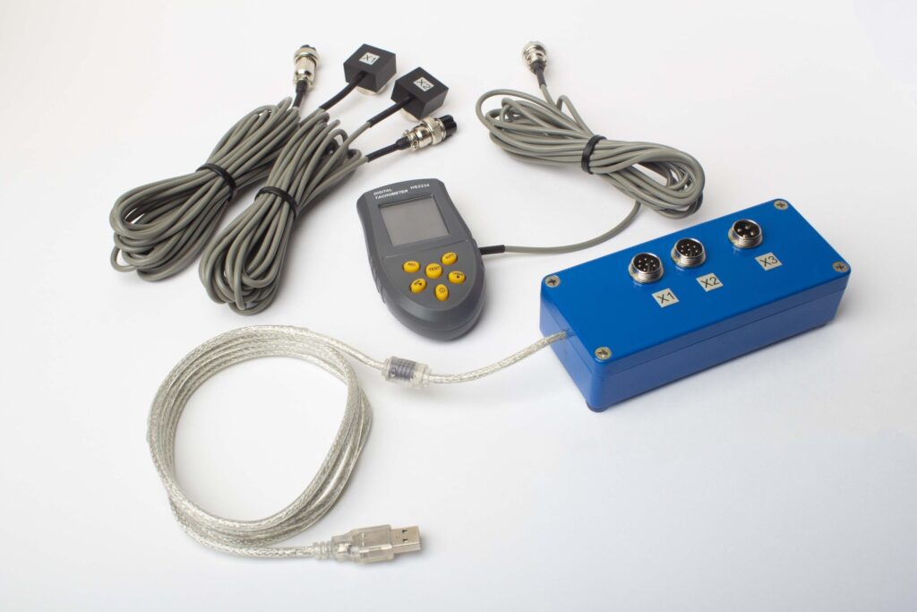
పూర్తి కిట్లో ఏముంది
€1,975 · పూర్తి కిట్, స్టాక్లో ఉంది, VAT ఇన్వాయిస్
- ఇంటర్ఫేస్ మెజర్మెంట్ యూనిట్ (USB, 2 చానెల్లు)
- రెండు వైబ్రేషన్ యాక్సెలెరోమీటర్లు (4 m కేబుల్, 10 m ఐచ్ఛికం)
- లేజర్ టాకోమీటర్ / ఆప్టికల్ ఫేజ్ సెన్సర్ (50–500 mm)
- సెన్సార్ కోసం మాగ్నెటిక్ స్టాండ్
- ట్రయల్ & కరెక్షన్ వెయిట్ల కోసం డిజిటల్ స్కేల్
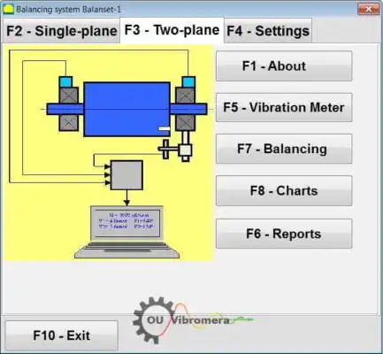
- Windows బ్యాలెన్సింగ్ & అనాలిసిస్ సాఫ్ట్వేర్
- ప్లాస్టిక్ ట్రాన్స్పోర్ట్ కేస్
Full Kit
యూనిట్ · 2 సెన్సార్లు · లేజర్ టాకోమీటర్ · మాగ్నెటిక్ స్టాండ్ · డిజిటల్ స్కేల్ · సాఫ్ట్వేర్ · ట్రాన్స్పోర్ట్ కేస్. బాక్స్ తెరిచిన వెంటనే బ్యాలన్సింగ్ ప్రారంభించడానికి అవసరమైనదంతా.
OEM set
యూనిట్ · 2 సెన్సార్లు · లేజర్ టాకోమీటర్ · సాఫ్ట్వేర్. ఇప్పటికే స్టాండ్, స్కేల్ మరియు కేస్ ఉన్న ఇంటిగ్రేటర్లకు, లేదా యూనిట్ను బ్యాలన్సింగ్ మెషీన్లో పొందుపరచాలనుకున్నవారికి.
| Parameter | Value |
|---|---|
| మెజర్మెంట్ చానెల్లు | 2 (సింగిల్-ప్లేన్ & టూ-ప్లేన్ బ్యాలెన్సింగ్) |
| వైబ్రేషన్ వేగం పరిధి | 0.2–80 mm/s RMS |
| పౌనఃపున్య పరిధి | 5–1000 Hz (≤10% amplitude error above 550 Hz) |
| కొలత ఖచ్చితత్వం | పూర్తి స్కేల్లో ±5% |
| Method | 3-రన్ ఇన్ఫ్లుయెన్స్-కో఼ఎఫిషియెంట్ (1 లేదా 2 ప్లేన్లు) |
| Analysis | 1× వద్ద ఆంప్లిట్యూడ్ & ఫేజ్, FFT స్పెక్ట్రమ్ & వేవ్ఫారమ్, సేవ్ అయిన రిపోర్టులు |
| Laptop | చేర్చబడలేదు (Windows PC, అభ్యర్థన మేరకు అందుబాటులో) |
ఫీల్డ్ బ్యాలెన్సింగ్ vs బ్యాలెన్సింగ్ మిషన్ — మీ పంప్కు ఏది సరైనది?
| Factor | క్షేత్ర సమతుల్యత (Balanset-1A) | సమతుల్యత యంత్రం (వర్క్షాప్) |
|---|---|---|
| పంప్ లైన్ నుండి తొలగించబడిందా? | లేదు — స్థానంలోనే నడుస్తుంది | అవును — పూర్తి విడదీయడం అవసరం |
| పైప్ డిస్కనెక్షన్ జరిగిందా? | No | Yes |
| ఉత్పత్తి నిలిపివేత | సెన్సార్ అమరిక మాత్రమే (<15 నిమి) | గంటల నుండి రోజుల వరకు (తీయడం, రవాణా, బాలెన్స్ చేయడం, తిరిగి అమర్చడం) |
| సమతుల్యత వేగం | వాస్తవ పని వేగం & పరిస్థితులు | ప్రత్యేక తక్కువ-వేగం స్పిండిల్ |
| కప్లింగ్ & షాఫ్ట్ ఫ్లెక్స్ను పరిగణనలోకి తీసుకుంటుంది | అవును — పూర్తి అసెంబ్లీ బ్యాలెన్స్ చేయబడింది | Impeller only |
| Standards met | ISO 21940-11, API 610 | ISO 21940-11 |
| Equipment cost | €1,975 (పూర్తి కిట్) | €10,000 – €50,000+ |
| సాధారణ పని సమయం | సైట్లో <1 గంట | మొత్తం 1–3 రోజులు |
పంప్ రన్ చేయగలిగినప్పుడు మరియు రోటర్ రిజిడిటీ ప్రమాణం సంతృప్తి చెందినప్పుడు ఫీల్డ్ బ్యాలెన్సింగ్ ఇష్టపడే ఎంపిక. వర్క్షాప్ మిషన్ రన్ టైమ్ అందుబాటులో లేని కొత్త-బిల్డ్ ఇంపెల్లర్లకు లేదా ఇతర కారణాల వల్ల విడదీయడం అవసరమయ్యే చాలా పెద్ద రోటర్లకు సముచితంగా ఉంటుంది.
వాస్తవ పంప్ బ్యాలెన్సింగ్ కేస్లు
హైడ్రాలిక్ పంపులు
వైబ్రేషన్ను తొలగించడానికి మరియు సీల్ జీవితకాలాన్ని పొడిగించడానికి హైడ్రాలిక్ పంప్ రోటర్ల ఫీల్డ్ బ్యాలెన్సింగ్.
వాక్యూమ్ పంప్ రోటర్లు
బేరింగ్ లోడ్లు మరియు శబ్దాన్ని తగ్గించడానికి వాక్యూమ్ పంప్ రోటర్లను స్వస్థానంలో బ్యాలెన్సింగ్ చేయడం.
వాక్యూమ్ పంప్ స్టాండ్
డాక్యుమెంటేడ్ ఫలితాలతో వాక్యూమ్ పంప్ రోటర్ల కోసం స్టాండ్-ఆధారిత బ్యాలెన్సింగ్ విధానం.
ఉచిత పంప్ కాలిక్యులేటర్లు
పంప్ బ్యాలెన్సింగ్ తరచుగా అడిగే ప్రశ్నలు
బ్యాలెన్సింగ్ కోసం పంప్ను పైప్ నుండి బయటకు తీయాల్సిన అవసరం ఉందా?
పంప్ ఇంపెల్లర్కు ఒక ప్లేన్ బ్యాలెన్సింగ్ అవసరమా లేదా రెండా?
నా పంపు వైబ్రేట్ అవుతోంది కానీ బేరింగ్లు కొత్తవి — అది ఇంకా అన్బ్యాలెన్స్ కావచ్చా?
సాధారణ పంపు బ్యాలెన్సింగ్ పని ఎంత సమయం తీసుకుంటుంది?
మేము Balanset-1A తో మేమే చేయగలమా?
పంపు ఇంపెల్లర్లు ఏ బ్యాలెన్స్ గ్రేడ్ను సాధించాలి?
సిద్ధాంతం నేర్చుకోండి
మీ పంపు ఇంపెల్లర్ను బ్యాలెన్స్ చేయండి — స్థానంలో, నేడే
Balanset-1A మిమ్మల్ని నడుస్తున్న వేగంలో సింగిల్- మరియు two-plane పంపు బ్యాలెన్సింగ్ ద్వారా నడిపిస్తుంది, ఖచ్చితమైన కరెక్షన్ వెయిట్ మరియు కోణాన్ని లెక్కిస్తుంది మరియు ఫలితాన్ని ISO 21940-11 మరియు API 610 కు డాక్యుమెంట్ చేస్తుంది. అన్మౌంటింగ్ లేదు, ఉత్పత్తి నష్టం లేదు — కేవలం నిశ్శబ్దంగా, ఎక్కువ కాలం మన్నే పంపు.
