ਬੈਲੇਂਸਿੰਗ ਸੇਵਾਵਾਂ › ਪੰਪ & ਇੰਪੈਲਰ
ਪੰਪ ਬੈਲੈਂਸਿੰਗ — ਇਨ-ਸੀਟੂ, ਓਪਰੇਟਿੰਗ ਸਪੀਡ 'ਤੇ
ਸੈਂਟਰੀਫਿਊਗਲ ਅਤੇ ਹਾਈਡ੍ਰੌਲਿਕ ਪੰਪ ਉਸ ਪਲ ਵਾਈਬ੍ਰੇਸ਼ਨ ਪੈਦਾ ਕਰਦੇ ਹਨ ਜਦੋਂ ਖੋਰ (corrosion), ਕੈਵੀਟੇਸ਼ਨ ਜਾਂ ਸਕੇਲ ਇੰਪੈਲਰ ਦੇ ਪੁੰਜ (mass) ਨੂੰ ਬਦਲ ਦਿੰਦੇ ਹਨ। ਅਸੀਂ ਪੰਪ ਰੋਟਰਾਂ ਨੂੰ ਬੈਲੈਂਸ ਕਰਦੇ ਹਾਂ ਸਥਾਨ 'ਤੇ ਹੀ, ਓਪਰੇਟਿੰਗ ਸਪੀਡ 'ਤੇ — ਕੇਸਿੰਗ ਤੋਂ ਕੋਈ ਹਟਾਉਣਾ ਨਹੀਂ, ਕੋਈ ਪਾਈਪ ਡਿਸਕਨੈਕਸ਼ਨ ਨਹੀਂ — ਇੱਕ ਹੀ ਆਨ-ਸਾਈਟ ਸੈਸ਼ਨ ਵਿੱਚ ਬੇਅਰਿੰਗ ਫੇਲ੍ਹ ਹੋਣ ਅਤੇ ਸੀਲ ਲੀਕ ਦੇ ਮੂਲ ਕਾਰਨ ਨੂੰ ਖਤਮ ਕਰਦੇ ਹੋਏ।
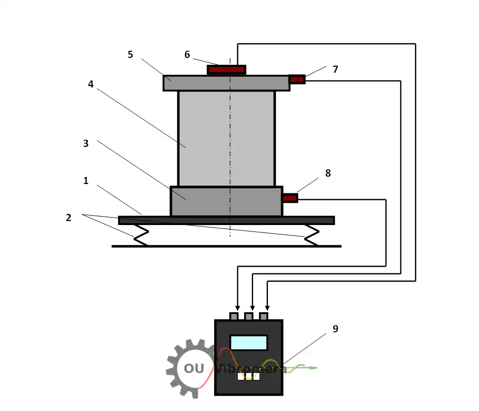
ਸੰਖੇਪ ਵਿੱਚ: ਪੰਪ-ਇੰਪੈਲਰ ਬੈਲੈਂਸਿੰਗ ਇਨ-ਸੀਟੂ, ਸਧਾਰਨ ਓਪਰੇਟਿੰਗ ਸਪੀਡ ਅਤੇ ਪ੍ਰੈਸ਼ਰ 'ਤੇ, ਇਨਫਲੂਐਂਸ-ਕੋਏਫੀਸ਼ੀਐਂਟ ਵਿਧੀ ਦੀ ਵਰਤੋਂ ਕਰਕੇ ਕੀਤੀ ਜਾਂਦੀ ਹੈ। ਬੇਅਰਿੰਗ ਹਾਊਸਿੰਗ 'ਤੇ ਇੱਕ ਵਾਈਬ੍ਰੇਸ਼ਨ ਸੈਂਸਰ ਅਤੇ ਸ਼ਾਫਟ 'ਤੇ ਇੱਕ ਲੇਜ਼ਰ ਟੈਕੋਮੀਟਰ ਅਨਬੈਲੈਂਸ ਸਥਿਤੀ ਨੂੰ ਮਾਪਦੇ ਹਨ; Balanset-1A ਸਟੀਕ ਕਰੈਕਸ਼ਨ ਪੁੰਜ ਅਤੇ ਕੋਣ ਦੀ ਗਣਨਾ ਕਰਦਾ ਹੈ। ਕੋਈ ਪੰਪ ਹਟਾਉਣਾ ਨਹੀਂ, ਕੋਈ ਪਾਈਪ ਦਾ ਕੰਮ ਨਹੀਂ — ਇੱਕ ਆਮ ਸਿੰਗਲ-ਸਟੇਜ ਜੌਬ ਇੱਕ ਘੰਟੇ ਤੋਂ ਘੱਟ ਸਮੇਂ ਵਿੱਚ ਪੂਰੀ ਹੋ ਜਾਂਦੀ ਹੈ, ਜੋ ਵਾਈਬ੍ਰੇਸ਼ਨ ਨੂੰ 70 % ਜਾਂ ਵੱਧ ਘਟਾਉਂਦੀ ਹੈ ਅਤੇ ਬੇਅਰਿੰਗ ਅਤੇ ਸੀਲ ਦੀ ਉਮਰ ਨੂੰ ਅੱਠ ਗੁਣਾ ਜਾਂ ਵੱਧ ਵਧਾਉਂਦੀ ਹੈ।
ਸੰਕੇਤ ਕਿ ਤੁਹਾਡਾ ਪੰਪ ਬੈਲੈਂਸ ਤੋਂ ਬਾਹਰ ਹੈ
ਪੰਪ ਵਾਈਬ੍ਰੇਸ਼ਨ ਨੂੰ ਅਕਸਰ ਸਧਾਰਨ ਮੰਨ ਲਿਆ ਜਾਂਦਾ ਹੈ, ਫਿਰ ਵੀ ਇਹਨਾਂ ਵਿੱਚੋਂ ਹਰੇਕ ਲੱਛਣ ਇੰਪੈਲਰ ਜਾਂ ਰੋਟਰ ਵਿੱਚ ਇੱਕ ਠੀਕ ਕੀਤੇ ਜਾ ਸਕਣ ਵਾਲੇ ਅਨਬੈਲੈਂਸ ਵੱਲ ਇਸ਼ਾਰਾ ਕਰਦਾ ਹੈ:
ਪੰਪ ਇੰਪੈਲਰ ਬੈਲੈਂਸ ਕਿਉਂ ਗੁਆਉਂਦੇ ਹਨ — ਅਤੇ ਇਸਦੀ ਕੀਮਤ ਕੀ ਹੈ
ਇੱਕ ਤਾਜ਼ਾ ਅਸੈਂਬਲ ਕੀਤਾ ਪੰਪ ਫੈਕਟਰੀ ਤੋਂ ਬੈਲੈਂਸਡ ਨਿਕਲਦਾ ਹੈ, ਪਰ ਸਰਵਿਸ ਹਾਲਤਾਂ ਲਗਾਤਾਰ ਉਸ ਬੈਲੈਂਸ 'ਤੇ ਹਮਲਾ ਕਰਦੀਆਂ ਰਹਿੰਦੀਆਂ ਹਨ। ਕੈਵੀਟੇਸ਼ਨ ਪਿਟਿੰਗ ਵੇਨ ਸਤਹਾਂ ਨੂੰ ਅਸਮਾਨ ਰੂਪ ਵਿੱਚ ਖੋਰਦੀ ਹੈ; ਘਸਾਊ ਸਲਰੀਆਂ ਇੰਪੈਲਰ ਦੇ ਇੱਕ ਪਾਸੇ ਨੂੰ ਦੂਜੇ ਨਾਲੋਂ ਤੇਜ਼ੀ ਨਾਲ ਘਸਾਉਂਦੀਆਂ ਹਨ; ਸਕੇਲ ਅਤੇ ਜਮ੍ਹਾਂ ਫਲੋ ਪੈਸੇਜਾਂ ਦੇ ਅੰਦਰ ਅਸਮਾਨ ਰੂਪ ਵਿੱਚ ਇਕੱਠੇ ਹੁੰਦੇ ਹਨ; ਵੈਲਡ ਮੁਰੰਮਤ ਜਾਂ ਬਦਲੀਆਂ ਵੀਅਰ ਰਿੰਗਾਂ ਅਸਮਿਤ ਪੁੰਜ ਜੋੜਦੀਆਂ ਹਨ। ਕਿਉਂਕਿ ਸੈਂਟਰੀਫਿਊਗਲ ਬਲ ਵਰਗ ਰੋਟੇਸ਼ਨਲ ਸਪੀਡ ਦੇ ਵਰਗ ਨਾਲ ਵਧਦਾ ਹੈ, 1,500 rpm 'ਤੇ ਕੁਝ ਗ੍ਰਾਮ ਦਾ ਆਫਸੈੱਟ 3,000 rpm 'ਤੇ ਦਸਾਂ ਕਿਲੋਨਿਊਟਨਾਂ ਦੇ ਹਿਲਾਉਣ ਵਾਲੇ ਬਲ ਵਿੱਚ ਬਦਲ ਜਾਂਦਾ ਹੈ।
ਵਿੱਤੀ ਨੁਕਸਾਨ ਤੇਜ਼ੀ ਨਾਲ ਵਧਦਾ ਹੈ: ਹਰ ਤਿੰਨ ਮਹੀਨਿਆਂ ਵਿੱਚ ਸੀਲ ਬਦਲੀ, ਬੇਅਰਿੰਗ ਚੇਂਜਆਊਟ, ਅਣਯੋਜਿਤ ਪ੍ਰੋਸੈਸ ਸ਼ੱਟਡਾਊਨ, ਅਤੇ ਲਾਈਨ ਤੋਂ ਪੰਪ ਕੱਢਣ ਦੀ ਲੇਬਰ ਲਾਗਤ। ਇੱਕ ਸਿੰਗਲ ਫੀਲਡ-ਬੈਲੈਂਸਿੰਗ ਸੈਸ਼ਨ — ਆਮ ਤੌਰ 'ਤੇ ਇੱਕ ਘੰਟੇ ਤੋਂ ਘੱਟ — ਉਸ ਡਾਇਨਾਮਿਕ ਲੋਡ ਨੂੰ ਹਟਾਉਂਦਾ ਹੈ ਜੋ ਇਹਨਾਂ ਸਾਰੀਆਂ ਫੇਲ੍ਹੀਆਂ ਲਈ ਜ਼ਿੰਮੇਵਾਰ ਹੈ, ਨਾ ਕਿ ਸਿਰਫ ਉਹਨਾਂ ਕੰਪੋਨੈਂਟਾਂ ਨੂੰ ਬਦਲਣਾ ਜਿਨ੍ਹਾਂ ਨੂੰ ਇਹ ਨਸ਼ਟ ਕਰਦਾ ਹੈ।
ਵਾਈਬ੍ਰੇਸ਼ਨ ਅੱਧੀ ਕਰਨ ਨਾਲ ਬੇਅਰਿੰਗ ਦੀ ਉਮਰ ਕਈ ਗੁਣਾ ਕਿਉਂ ਵਧਦੀ ਹੈ
ਅਸੀਂ ਪੰਪ ਨੂੰ ਕਿਵੇਂ ਬੈਲੈਂਸ ਕਰਦੇ ਹਾਂ — ਕਦਮ-ਦਰ-ਕਦਮ
Balanset-1A ਨਾਲ ਫੀਲਡ ਬੈਲੈਂਸਿੰਗ ਇਨਫਲੂਐਂਸ-ਕੋਏਫੀਸ਼ੀਐਂਟ ਵਿਧੀ ਦੀ ਪਾਲਣਾ ਕਰਦੀ ਹੈ — ਉਹੀ ਵਿਵਸਥਿਤ ਪ੍ਰਕਿਰਿਆ ਜੋ ਤੁਸੀਂ ਖੁਦ ਸਾਈਟ 'ਤੇ ਕਰ ਸਕਦੇ ਹੋ:
- ਸੈਂਸਰ ਲਗਾਓ। ਇੱਕ ਵਾਈਬ੍ਰੇਸ਼ਨ ਐਕਸਲਰੋਮੀਟਰ ਪੰਪ ਬੇਅਰਿੰਗ ਹਾਊਸਿੰਗ 'ਤੇ ਲਗਾਇਆ ਜਾਂਦਾ ਹੈ ਅਤੇ ਇੱਕ ਲੇਜ਼ਰ ਟੈਕੋਮੀਟਰ ਸ਼ਾਫਟ 'ਤੇ ਇੱਕ ਰਿਫਲੈਕਟਿਵ ਸਟ੍ਰਿਪ ਵੱਲ ਸੇਧਿਤ ਕੀਤਾ ਜਾਂਦਾ ਹੈ। ਕੋਈ ਡਿਸਅਸੈਂਬਲੀ ਲੋੜੀਂਦੀ ਨਹੀਂ — ਪੰਪ ਪੂਰੇ ਸਮੇਂ ਆਮ ਓਪਰੇਟਿੰਗ ਹਾਲਤਾਂ ਹੇਠ ਚੱਲਦਾ ਹੈ।
- ਬੇਸਲਾਈਨ ਮਾਪ ਲਓ। ਪੂਰੀ ਓਪਰੇਟਿੰਗ ਸਪੀਡ 'ਤੇ ਇੱਕ ਰਨ ਵਾਈਬ੍ਰੇਸ਼ਨ ਐਮਪਲੀਟਿਊਡ ਅਤੇ ਫੇਜ਼ ਐਂਗਲ ਰਿਕਾਰਡ ਕਰਦਾ ਹੈ, ਜੋ ਐਮਪਲੀਟਿਊਡ ਅਤੇ ਦਿਸ਼ਾ ਵਿੱਚ ਮੌਜੂਦਾ ਅਨਬੈਲੈਂਸ ਸਥਿਤੀ ਸਥਾਪਿਤ ਕਰਦਾ ਹੈ।
- ਟ੍ਰਾਇਲ ਵੇਟ ਲਗਾਓ। ਇੱਕ ਜਾਣਿਆ-ਪਛਾਣਿਆ ਟੈਸਟ ਪੁੰਜ ਇੰਪੈਲਰ ਹੱਬ ਜਾਂ ਬੈਲੈਂਸ ਰਿੰਗ 'ਤੇ ਕਲੈਂਪ ਕੀਤਾ ਜਾਂਦਾ ਹੈ। ਦੂਜਾ ਰਨ ਦਿਖਾਉਂਦਾ ਹੈ ਕਿ ਰੋਟਰ ਇੱਕ ਜਾਣੇ-ਪਛਾਣੇ ਐਂਗੁਲਰ ਸਥਾਨ 'ਤੇ ਇੱਕ ਖਾਸ ਵਜ਼ਨ ਪ੍ਰਤੀ ਕਿਵੇਂ ਪ੍ਰਤੀਕਿਰਿਆ ਕਰਦਾ ਹੈ — ਇਨਫਲੂਐਂਸ ਕੋਐਫੀਸ਼ੀਐਂਟ।
- ਉਪਕਰਨ ਨੂੰ ਗਣਨਾ ਕਰਨ ਦਿਓ। Balanset-1A ਸਟੀਕ ਕਰੈਕਸ਼ਨ ਪੁੰਜ ਅਤੇ ਐਂਗੁਲਰ ਪਲੇਸਮੈਂਟ ਦੀ ਗਣਨਾ ਕਰਨ ਲਈ ਇਨਫਲੂਐਂਸ-ਕੋਏਫੀਸ਼ੀਐਂਟ ਐਲਗੋਰਿਦਮ ਲਾਗੂ ਕਰਦਾ ਹੈ — ਕੰਪੈਕਟ ਬੰਦ ਇੰਪੈਲਰਾਂ ਲਈ ਇੱਕ ਪਲੇਨ, ਚੌੜੇ ਡਬਲ-ਸਕਸ਼ਨ ਰੋਟਰਾਂ ਜਾਂ ਲੰਬੀਆਂ ਮਲਟੀ-ਸਟੇਜ ਸ਼ਾਫਟ ਅਸੈਂਬਲੀਆਂ ਲਈ ਦੋ ਪਲੇਨ।
- ਸੁਧਾਰ ਵਜ਼ਨ ਫਿੱਟ ਕਰੋ। ਇੰਪੈਲਰ ਹੱਬ, ਵੇਨ, ਜਾਂ ਬੈਲੈਂਸ ਰਿੰਗ 'ਤੇ ਦਰਸਾਈ ਗਈ ਸਥਿਤੀ 'ਤੇ ਗਣਨਾ ਕੀਤੇ ਪੁੰਜ ਨੂੰ ਵੈਲਡ, ਬੋਲਟ ਜਾਂ ਕਲੈਂਪ ਕਰੋ। ਟ੍ਰਾਇਲ ਵਜ਼ਨ ਹਟਾਓ ਜਦੋਂ ਤੱਕ ਇਹ ਹੱਲ ਦਾ ਹਿੱਸਾ ਨਾ ਹੋਵੇ।
- ਤਸਦੀਕ ਕਰੋ ਅਤੇ ਦਸਤਾਵੇਜ਼ੀਕਰਨ ਕਰੋ। ਇੱਕ ਅੰਤਿਮ ਮਾਪ ਰਨ ਪੁਸ਼ਟੀ ਕਰਦਾ ਹੈ ਕਿ ਰੈਜ਼ੀਡੁਅਲ ਅਨਬੈਲੈਂਸ ਪੰਪ ਦੀ ਬੈਲੈਂਸ ਗ੍ਰੇਡ ਲਈ ISO ਟਾਲਰੈਂਸ ਬੈਂਡ ਦੇ ਅੰਦਰ ਹੈ। Balanset-1A ਮੇਨਟੇਨੈਂਸ ਰਿਕਾਰਡਾਂ ਲਈ ਇੱਕ ਬੈਲੈਂਸਿੰਗ ਰਿਪੋਰਟ ਪ੍ਰਿੰਟ ਕਰਦਾ ਹੈ।
ਅਸੀਂ ਕੀ ਬੈਲੇਂਸ ਕਰਦੇ ਹਾਂ
- ਸਿੰਗਲ-ਸਟੇਜ ਸੈਂਟਰੀਫਿਊਗਲ ਪੰਪ ਇੰਪੈਲਰ
- ਮਲਟੀ-ਸਟੇਜ ਪੰਪ ਸ਼ਾਫਟ ਅਸੈਂਬਲੀਆਂ
- ਡਬਲ-ਸਕਸ਼ਨ (ਦੋ-ਪਲੇਨ) ਇੰਪੈਲਰ
- ਹਾਈਡ੍ਰੌਲਿਕ ਪੰਪ ਰੋਟਰ
- ਵੈਕਿਊਮ ਪੰਪ ਰੋਟਰ
- ਸਬਮਰਸੀਬਲ ਪੰਪ ਇੰਪੈਲਰ
- ਸਲਰੀ ਅਤੇ ਕੈਮੀਕਲ ਪੰਪ ਇੰਪੈਲਰ
- ਇਨਲਾਈਨ ਅਤੇ ਐਂਡ-ਸਕਸ਼ਨ ਪੰਪ ਰੋਟਰ
- ਫਾਇਰ ਅਤੇ ਬੂਸਟਰ ਪੰਪ ਇੰਪੈਲਰ
- ਸਰਕੂਲੇਸ਼ਨ ਅਤੇ ਕੂਲਿੰਗ-ਵਾਟਰ ਪੰਪ ਇੰਪੈਲਰ
ਸਹਿਣਸ਼ੀਲਤਾਵਾਂ & ਮਿਆਰ
ISO 21940-11 (ਪਹਿਲਾਂ ISO 1940-1) G0.4 ਤੋਂ G4000 ਤੱਕ ਰਿਜਿਡ-ਰੋਟਰ ਬੈਲੈਂਸ ਕੁਆਲਿਟੀ ਗ੍ਰੇਡ ਪਰਿਭਾਸ਼ਿਤ ਕਰਦਾ ਹੈ। ਜ਼ਿਆਦਾਤਰ ਪ੍ਰੋਸੈਸ ਪੰਪ ਇੰਪੈਲਰ ਇਸ ਤੱਕ ਬੈਲੈਂਸ ਕੀਤੇ ਜਾਂਦੇ ਹਨ G2.5 ਜਾਂ G1.0 — ਵੱਧ ਪੈਰੀਫਿਰਲ ਸਪੀਡ ਜਾਂ ਸਟੀਕ ਮਕੈਨੀਕਲ ਸੀਲਾਂ ਵਾਲੀਆਂ ਮਸ਼ੀਨਾਂ ਲਈ ਢੁਕਵੇਂ ਸਖ਼ਤ ਗ੍ਰੇਡ।
ਪ੍ਰੋਸੈਸ-ਪਲਾਂਟ ਸੰਦਰਭਾਂ ਵਿੱਚ, API 610 further specifies residual unbalance limits for centrifugal pumps in hydrocarbon service, requiring each rotating assembly to achieve a maximum residual unbalance per correction plane of Umax = 6350W/N (g·mm), where W is the journal static load for that correction plane in kg and N is the maximum continuous speed in rpm (the equivalent imperial form is 4W/N oz·in with W in lb). We balance to the grade your application demands and supply documented residual-unbalance figures for your maintenance records. Use our ਬਾਕੀ-ਬਚੇ ਅਸੰਤੁਲਨ ਕੈਲਕੁਲੇਟਰ ਸ਼ੁਰੂ ਕਰਨ ਤੋਂ ਪਹਿਲਾਂ ਆਪਣੀ ਮਨਜ਼ੂਰਸ਼ੁਦਾ ਸਹਿਣਸ਼ੀਲਤਾ ਲੱਭਣ ਲਈ।
Balanset-1A — ਤੁਹਾਡੀ ਸੰਪੂਰਨ ਸਾਈਟ-ਬੈਲੇਂਸਿੰਗ ਕਿੱਟ
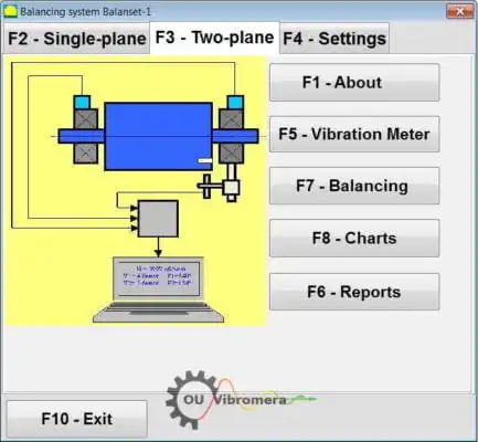
ਇਸ ਪੰਨੇ 'ਤੇ ਸਭ ਕੁਝ ਇੱਕ ਪੋਰਟੇਬਲ ਯੰਤਰ ਨਾਲ ਕੀਤਾ ਜਾਂਦਾ ਹੈ: Balanset-1Aਵਰਤੋ। ਇਹ ਇੱਕ ਦੋ-ਚੈਨਲ ਡਾਇਨਾਮਿਕ ਬੈਲੈਂਸਰ ਅਤੇ ਵਾਈਬ੍ਰੇਸ਼ਨ ਵਿਸ਼ਲੇਸ਼ਕ ਹੈ ਜੋ ਪੰਪ ਰੋਟਰਾਂ ਨੂੰ ਸੰਤੁਲਿਤ ਕਰਦਾ ਹੈ ਆਪਣੇ ਬੇਅਰਿੰਗਾਂ ਵਿੱਚ, ਓਪਰੇਟਿੰਗ ਗਤੀ 'ਤੇ, 3-ਰਨ ਪ੍ਰਭਾਵ-ਗੁਣਾਂਕ ਵਿਧੀ ਦੀ ਵਰਤੋਂ ਕਰਕੇ — ਸੌਫ਼ਟਵੇਅਰ ਸਹੀ ਸੁਧਾਰ ਪੁੰਜ ਅਤੇ ਕੋਣ ਦੀ ਗਣਨਾ ਕਰਦਾ ਹੈ ਅਤੇ ਇੱਕ ਰਿਪੋਰਟ ਸੁਰੱਖਿਅਤ ਕਰਦਾ ਹੈ।
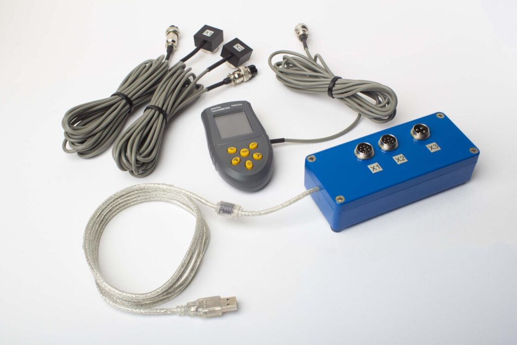
ਪੂਰੇ ਕਿੱਟ ਵਿੱਚ ਕੀ ਸ਼ਾਮਲ ਹੈ
€1,975 · ਪੂਰਾ ਕਿੱਟ, ਸਟਾਕ ਵਿੱਚ, VAT ਇਨਵੌਇਸ
- ਇੰਟਰਫੇਸ ਮਾਪ ਇਕਾਈ (USB, 2 ਚੈਨਲ)
- ਦੋ ਵਾਈਬ੍ਰੇਸ਼ਨ ਐਕਸੇਲੇਰੋਮੀਟਰ (4 m ਕੇਬਲ, 10 m ਵਿਕਲਪਿਕ)
- ਲੇਜ਼ਰ ਟੈਕੋਮੀਟਰ / ਆਪਟੀਕਲ ਫੇਜ਼ ਸੈਂਸਰ (50–500 mm)
- ਸੈਂਸਰ ਲਈ ਮੈਗਨੈਟਿਕ ਸਟੈਂਡ
- ਟਰਾਇਲ & ਸੁਧਾਰ ਵਜ਼ਨ ਲਈ ਡਿਜੀਟਲ ਸਕੇਲ
- Windows ਬੈਲੇਂਸਿੰਗ & ਵਿਸ਼ਲੇਸ਼ਣ ਸੌਫ਼ਟਵੇਅਰ
- ਪਲਾਸਟਿਕ ਟਰਾਂਸਪੋਰਟ ਕੇਸ
ਪੂਰੀ ਕਿੱਟ
ਇਕਾਈ · 2 ਸੈਂਸਰ · ਲੇਜ਼ਰ ਟੈਕੋਮੀਟਰ · ਮੈਗਨੈਟਿਕ ਸਟੈਂਡ · ਡਿਜੀਟਲ ਸਕੇਲ · ਸੌਫ਼ਟਵੇਅਰ · ਟਰਾਂਸਪੋਰਟ ਕੇਸ। ਬਾਕਸ ਤੋਂ ਬਾਹਰ ਬੈਲੇਂਸਿੰਗ ਸ਼ੁਰੂ ਕਰਨ ਲਈ ਸਭ ਕੁਝ ਲੋੜੀਂਦਾ।
OEM ਸੈੱਟ
ਇਕਾਈ · 2 ਸੈਂਸਰ · ਲੇਜ਼ਰ ਟੈਕੋਮੀਟਰ · ਸੌਫ਼ਟਵੇਅਰ। ਉਹਨਾਂ ਇੰਟੀਗ੍ਰੇਟਰਾਂ ਲਈ ਜਿਨ੍ਹਾਂ ਕੋਲ ਪਹਿਲਾਂ ਤੋਂ ਸਟੈਂਡ, ਸਕੇਲ ਅਤੇ ਕੇਸ ਹੈ, ਜਾਂ ਜੋ ਇਕਾਈ ਨੂੰ ਬੈਲੇਂਸਿੰਗ ਮਸ਼ੀਨ ਵਿੱਚ ਏਮਬੈੱਡ ਕਰਦੇ ਹਨ।
| ਪੈਰਾਮੀਟਰ | ਮੁੱਲ |
|---|---|
| ਮਾਪ ਚੈਨਲ | 2 (ਸਿੰਗਲ- & ਟੂ-ਪਲੇਨ ਬੈਲੇਂਸਿੰਗ) |
| ਵਾਈਬ੍ਰੇਸ਼ਨ ਵੇਲੋਸਿਟੀ ਰੇਂਜ | 0.2–80 mm/s RMS |
| ਫ੍ਰੀਕੁਐਂਸੀ ਰੇਂਜ | 5–1000 Hz (≤10% amplitude error above 550 Hz) |
| ਮਾਪ ਸ਼ੁੱਧਤਾ | ±5% ਪੂਰੇ ਸਕੇਲ ਦਾ |
| ਵਿਧੀ | 3-ਰਨ ਇਨਫਲੂਐਂਸ-ਕੋਏਫੀਸ਼ੀਐਂਟ (1 ਜਾਂ 2 ਸੁਧਾਰ-ਪਲੇਨ) |
| ਵਿਸ਼ਲੇਸ਼ਣ | 1× 'ਤੇ ਐਂਪਲੀਟਿਊਡ & ਫੇਜ਼, FFT ਸਪੈਕਟ੍ਰਮ & ਵੇਵਫਾਰਮ, ਸੁਰੱਖਿਅਤ ਰਿਪੋਰਟਾਂ |
| ਲੈਪਟਾਪ | ਸ਼ਾਮਲ ਨਹੀਂ (Windows PC, ਬੇਨਤੀ 'ਤੇ ਉਪਲਬਧ) |
ਫੀਲਡ ਬੈਲੈਂਸਿੰਗ ਬਨਾਮ ਬੈਲੈਂਸਿੰਗ ਮਸ਼ੀਨ — ਤੁਹਾਡੇ ਪੰਪ ਲਈ ਕਿਹੜਾ ਸਹੀ ਹੈ?
| ਫੈਕਟਰ | ਫੀਲਡ ਬੈਲੇਂਸਿੰਗ (Balanset-1A) | ਬੈਲੇਂਸਿੰਗ ਮਸ਼ੀਨ (ਵਰਕਸ਼ਾਪ) |
|---|---|---|
| ਕੀ ਪੰਪ ਲਾਈਨ ਤੋਂ ਹਟਾਇਆ ਗਿਆ? | ਨਹੀਂ — ਆਪਣੀ ਥਾਂ 'ਤੇ ਚੱਲਦਾ ਹੈ | ਹਾਂ — ਪੂਰੀ ਵੱਖ ਕਰਨ ਦੀ ਲੋੜ ਹੈ |
| ਪਾਈਪ ਡਿਸਕਨੈਕਸ਼ਨ? | ਨਹੀਂ | ਹਾਂ |
| ਉਤਪਾਦਨ ਬੰਦ ਸਮਾਂ | ਸਿਰਫ਼ ਸੈਂਸਰ ਲਗਾਉਣਾ (<15 ਮਿੰਟ) | ਘੰਟਿਆਂ ਤੋਂ ਦਿਨਾਂ ਤੱਕ (ਹਟਾਓ, ਭੇਜੋ, ਸੰਤੁਲਿਤ ਕਰੋ, ਮੁੜ ਸਥਾਪਿਤ ਕਰੋ) |
| ਬੈਲੇਂਸਿੰਗ ਗਤੀ | ਅਸਲ ਸੰਚਾਲਨ ਗਤੀ & ਹਾਲਤਾਂ | ਵੱਖਰਾ ਘੱਟ-ਗਤੀ ਸਪਿੰਡਲ |
| ਕਪਲਿੰਗ & ਸ਼ਾਫਟ ਫਲੈਕਸ ਨੂੰ ਧਿਆਨ ਵਿੱਚ ਰੱਖਦਾ ਹੈ | ਹਾਂ — ਪੂਰੀ ਅਸੈਂਬਲੀ ਬੈਲੰਸ ਕੀਤੀ ਗਈ | ਸਿਰਫ਼ ਇੰਪੈਲਰ |
| ਪੂਰੇ ਕੀਤੇ ਗਏ ਮਿਆਰ | ISO 21940-11, API 610 | ISO 21940-11 |
| ਉਪਕਰਣ ਦੀ ਲਾਗਤ | €1,975 (ਪੂਰਾ ਕਿੱਟ) | €10,000 – €50,000+ |
| ਆਮ ਕੰਮ ਦਾ ਸਮਾਂ | ਸਾਈਟ 'ਤੇ <1 ਘੰਟਾ | ਕੁੱਲ 1–3 ਦਿਨ |
ਫੀਲਡ ਬੈਲੈਂਸਿੰਗ ਤਰਜੀਹੀ ਵਿਕਲਪ ਹੈ ਜਦੋਂ ਵੀ ਪੰਪ ਚੱਲ ਸਕਦਾ ਹੈ ਅਤੇ ਰੋਟਰ ਦੀ ਕਠੋਰਤਾ ਦੀ ਸ਼ਰਤ ਪੂਰੀ ਹੁੰਦੀ ਹੈ। ਇੱਕ ਵਰਕਸ਼ਾਪ ਮਸ਼ੀਨ ਨਵੇਂ-ਬਣੇ ਇੰਪੈਲਰਾਂ ਲਈ ਢੁਕਵੀਂ ਰਹਿੰਦੀ ਹੈ ਜਿੱਥੇ ਕੋਈ ਚਲਾਉਣ ਦਾ ਸਮਾਂ ਉਪਲਬਧ ਨਹੀਂ, ਜਾਂ ਬਹੁਤ ਵੱਡੇ ਰੋਟਰਾਂ ਲਈ ਜਿਨ੍ਹਾਂ ਨੂੰ ਹੋਰ ਕਾਰਨਾਂ ਕਰਕੇ ਖੋਲ੍ਹਣ ਦੀ ਲੋੜ ਹੁੰਦੀ ਹੈ।
ਅਸਲ ਪੰਪ-ਬੈਲੈਂਸਿੰਗ ਕੇਸ
ਮੁਫ਼ਤ ਪੰਪ ਕੈਲਕੁਲੇਟਰ
ਪੰਪ ਬੈਲੈਂਸਿੰਗ FAQ
ਕੀ ਬੈਲੈਂਸਿੰਗ ਲਈ ਪੰਪ ਨੂੰ ਪਾਈਪ ਤੋਂ ਕੱਢਣਾ ਜ਼ਰੂਰੀ ਹੈ?
ਪੰਪ ਇੰਪੈਲਰ ਲਈ ਇੱਕ ਪਲੇਨ ਜਾਂ ਦੋ?
ਮੇਰਾ ਪੰਪ ਵਾਈਬ੍ਰੇਟ ਕਰਦਾ ਹੈ ਪਰ ਬੇਅਰਿੰਗ ਨਵੇਂ ਹਨ — ਕੀ ਇਹ ਫਿਰ ਵੀ ਅਸੰਤੁਲਨ ਹੈ?
ਇੱਕ ਆਮ ਪੰਪ ਬੈਲੈਂਸਿੰਗ ਕੰਮ ਵਿੱਚ ਕਿੰਨਾ ਸਮਾਂ ਲੱਗਦਾ ਹੈ?
ਕੀ ਅਸੀਂ ਇਹ ਖੁਦ Balanset-1A ਨਾਲ ਕਰ ਸਕਦੇ ਹਾਂ?
ਪੰਪ ਇੰਪੈਲਰਾਂ ਨੂੰ ਕਿਹੜਾ ਬੈਲੈਂਸ ਗ੍ਰੇਡ ਪੂਰਾ ਕਰਨ ਦੀ ਲੋੜ ਹੈ?
ਸਿਧਾਂਤ ਸਿੱਖੋ
ਆਪਣੇ ਪੰਪ ਇੰਪੈਲਰ ਨੂੰ ਸੰਤੁਲਿਤ ਕਰੋ — ਥਾਂ 'ਤੇ ਹੀ, ਅੱਜ
Balanset-1A ਤੁਹਾਨੂੰ ਚੱਲਦੀ ਸਪੀਡ 'ਤੇ ਸਿੰਗਲ- ਅਤੇ ਦੋ-ਪਲੇਨ ਪੰਪ ਬੈਲੈਂਸਿੰਗ ਵਿੱਚੋਂ ਲੰਘਾਉਂਦਾ ਹੈ, ਸਹੀ ਕਰੈਕਸ਼ਨ ਵਜ਼ਨ ਅਤੇ ਕੋਣ ਦੀ ਗਣਨਾ ਕਰਦਾ ਹੈ, ਅਤੇ ISO 21940-11 ਅਤੇ API 610 ਦੇ ਅਨੁਸਾਰ ਨਤੀਜੇ ਦਾ ਦਸਤਾਵੇਜ਼ੀਕਰਨ ਕਰਦਾ ਹੈ। ਕੋਈ ਖੋਲ੍ਹਣਾ ਨਹੀਂ, ਕੋਈ ਉਤਪਾਦਨ ਦਾ ਨੁਕਸਾਨ ਨਹੀਂ — ਸਿਰਫ਼ ਇੱਕ ਸ਼ਾਂਤ, ਲੰਬੇ ਸਮੇਂ ਤੱਕ ਚੱਲਣ ਵਾਲਾ ਪੰਪ।
