€1,975.00–€2,025.00Price range: €1,975.00 through €2,025.00 + PDV (ako se primjenjuje)
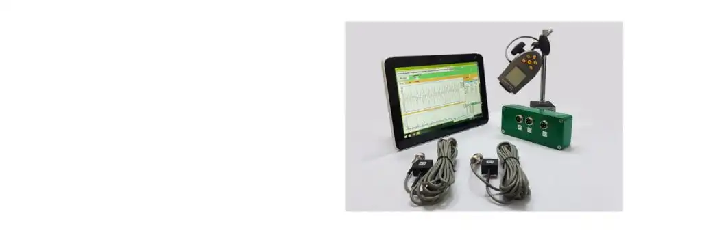
Balanset-1A je prenosivi analizator vibracija i balanser napajan preko USB-a za jednoravansko i dvoravansko balansiranje rotora u njihovim sopstvenim ležajevima. Full Kit uključuje interfejs jedinicu, dva senzora vibracija, optički laserski tahometar, reflektujuću traku, Windows softver za balansiranje na USB flash disku, magnetni stalak, digitalnu vagu i transportni kofer. Zahtijeva kompatibilan Windows računar sa slobodnim USB portom; računar nije uključen. Senzori i softver mjere vibraciju i izračunavaju korekcionu masu i ugao iz mjerenja s probnim utegom.
(Informacije preuzete iz GOST 31350-2007 “VIBRACIJE. INDUSTRIJSKI VENTILATORI. ZAHTJEVI ZA PROIZVEDENE VIBRACIJE I KVALITET BALANSIRANJA” — međudržavni standard razvijen na osnovu ISO 14694:2003 “Industrijski ventilatori — Specifikacije za kvalitet balansa i nivoe vibracija”)
Napomena o izvoru: ova stranica se zasniva na zahtjevima za vibracije i kvalitet balansa ventilatora ekvivalentnim standardu ISO 14694:2003 i srodnim međudržavnim (GOST) usvajanjima ISO standarda, čije se oznake razlikuju od originalnih brojeva ISO publikacija. Tamo gdje se pojavljuje starija terminologija ISO 1940-1, važeći standard kvaliteta balansa je ISO 21940-11 (ranije ISO 1940-1).
Vibracija Vibracije koje proizvodi ventilator jedna su od njegovih najvažnijih tehničkih karakteristika. Označava kvalitetu dizajna i izrade proizvoda. Pojačane vibracije mogu ukazivati na nepravilnu ugradnju ventilatora, pogoršanje njegovog tehničkog stanja itd. Zbog toga se vibracije ventilatora obično mjere prilikom prijemnih testova, prilikom ugradnje prije puštanja u rad, kao i prilikom izvođenja programa praćenja stanja mašine. Podaci o vibracijama ventilatora se također koriste u dizajnu njegovih potpornih i povezanih sistema (kanala). Mjerenja vibracija se obično izvode s otvorenim usisnim i ispusnim otvorima, ali treba napomenuti da vibracije ventilatora mogu značajno varirati s promjenama u aerodinamici protoka zraka, brzini rotacije i drugim karakteristikama.
GOST ISO 10816-1-97 (ISO 10816-1:1995), GOST ISO 10816-3-2002 (ISO 10816-3:1998) i GOST 31351-2007 (ISO 14695:2003) utvrđuju metode mjerenja i definišu lokacije senzora vibracija. Ako se mjerenja vibracija vrše radi procjene njihovog uticaja na kanal ili postolje ventilatora, mjerne tačke se biraju u skladu s tim.
Mjerenja vibracija ventilatora mogu biti skupa, a ponekad njihova cijena znatno premašuje cijenu proizvodnje samog proizvoda. Stoga, sva ograničenja na vrijednosti pojedinačnih diskretnih komponenti vibracija ili parametara vibracija u frekvencijskim opsezima treba uvesti samo kada prekoračenje ovih vrijednosti ukazuje na kvar ventilatora. Broj mjernih tačaka vibracija također treba ograničiti na osnovu namjeravane upotrebe rezultata mjerenja. Obično je dovoljno izmjeriti vibracije na nosačima ventilatora da bi se procijenilo vibraciono stanje ventilatora.
Osnova je ono na šta je ventilator montiran i ono što obezbeđuje neophodnu podršku za ventilator. Masa i krutost podloge se biraju kako bi se spriječilo pojačanje vibracije koja se prenosi kroz nju.
Nosači su dvije vrste:
elastični oslonac: Sistem oslanjanja ventilatora projektovan tako da je prva sopstvena frekvencija oslonca znatno niža od radne frekvencije rotacije ventilatora. Pri određivanju stepena elastičnosti oslonca treba uzeti u obzir elastične umetke između ventilatora i noseće konstrukcije. Elastičnost oslonca se obezbjeđuje vješanjem ventilatora na opruge ili postavljanjem oslonca na elastične elemente (opruge, gumene izolatore itd.). Sopstvena frekvencija sistema ovjesa – ventilatora obično je manja od 25% frekvencije koja odgovara minimalnoj brzini rotacije ispitivanog ventilatora.
kruti oslonac: Sistem oslonca ventilatora projektovan tako da je prva vlastita frekvencija oslonca znatno viša od radne frekvencije rotacije. Krutost osnove ventilatora je relativna. Treba je razmatrati u poređenju s krutošću ležajeva mašine. Omjer vibracija kućišta ležaja i vibracija osnove karakterizira utjecaj podatljivosti osnove. Osnova se može smatrati krutom i dovoljno masivnom ako je amplituda vibracija osnove (u bilo kojem smjeru) u blizini nogu mašine ili potpornog okvira manja od 25% maksimalnog rezultata mjerenja vibracija dobivenog na najbližem osloncu ležaja (u bilo kojem smjeru).
Budući da se masa i krutost privremene osnove na koju je ventilator montiran tokom tvorničkih ispitivanja mogu znatno razlikovati od uvjeta ugradnje na mjestu rada, granične vrijednosti za tvorničke uvjete odnose se na uskopojasne vibracije u opsegu frekvencije rotacije, a za ispitivanje ventilatora na licu mjesta – na širokopojasne vibracije, koje određuju ukupno vibracijsko stanje mašine. Mjesto rada je konačno mjesto ugradnje ventilatora, za koje su definirani radni uvjeti.
Kategorije ventilatora (BV-kategorije)
Ventilatori se kategoriziraju na osnovu karakteristika njihove namjenjirane upotrebe, klase tačnosti balansiranja, i preporučene vrijednosti granica parametara vibracija. Dizajn i namjena ventilatora su kriteriji koji omogućavaju klasifikaciju mnogih tipova ventilatora prema prihvatljivim neuravnoteženost vrijednosti i nivoi vibracija (BV-kategorije).
U tabeli 1 prikazane su kategorije kojima se ventilatori mogu pripisati na osnovu uslova njihove primene, s obzirom na dozvoljene vrednosti neravnoteže i nivoe vibracija. Kategoriju ventilatora određuje proizvođač.
Tabela 1 – Kategorije ventilatora
Uslovi primjene
Primjeri
Potrošnja energije, kW
BV-kategorija
Stambeni i poslovni prostori
Ventilatori na stropu i potkrovlju, klima uređaji za prozore
≤ 0,15
BV-1
> 0,15
BV-2
Zgrade i poljoprivredne prostorije
Ventilatori za sisteme ventilacije i klimatizacije; Ventilatori u serijskoj opremi
≤ 3.7
BV-2
> 3.7
BV-3
Industrijski procesi i proizvodnja energije
Ventilatori u zatvorenim prostorima, rudnicima, transporterima, bojlerima, aerotunelima, sistemima za čišćenje gasa
≤ 300
BV-3
> 300
vidi ISO 10816-3
Transport, uključujući pomorska plovila
Ventilatori na lokomotivama, kamionima i automobilima
≤ 15
BV-3
> 15
BV-4
Tuneli
Ventilatori za ventilaciju metroa, tunela, garaža
≤ 75
BV-3
> 75
BV-4
Bilo koji
BV-4
Petrohemijska proizvodnja
Ventilatori za odvođenje opasnih gasova, a koriste se u drugim tehnološkim procesima
≤ 37
BV-3
> 37
BV-4
Proizvodnja kompjuterskih čipova
Ventilatori za stvaranje čistih soba
Bilo koji
BV-5
Napomene
1 Ovaj standard razmatra samo ventilatore sa snagom manjom od 300 kW. Procjena vibracija ventilatora sa većom snagom vrši se prema ISO 10816-3. Međutim, standardni serijski električni motori mogu imati nominalnu snagu do 355 kW. Ventilatori sa takvim električnim motorima trebaju biti prihvaćeni prema ovom standardu.
2 Tabela 1 ne važi za niskobrzinske lagane aksijalne ventilatore velikog prečnika (obično od 2800 do 12500 mm) koji se koriste u izmjenjivačima toplote, rashladnim tornjevima itd. Klasa tačnosti balansiranja za takve ventilatore treba biti G16, a kategorija ventilatora – BV-3
Pri kupovini pojedinačnih elemenata rotora (točkova ili radnih kola) za naknadnu instalaciju na ventilator, treba poštovati klasu tačnosti balansiranja ovih elemenata (vidi tabelu 2), a pri kupovini ventilatora kao cjeline, treba uzeti u obzir i rezultate fabričkih vibracijskih testova (tabela 4) i vibracija na licu mjesta (tabela 5). Obično se ove karakteristike dogovaraju, tako da izbor ventilatora može biti zasnovan na njegovoj BV-kategoriji.
Kategorija utvrđena u tabeli 1 tipična je za uobičajenu upotrebu ventilatora, ali u opravdanim slučajevima naručilac može zatražiti ventilator druge BV-kategorije. Preporučuje se da se BV-kategorija ventilatora, klasa tačnosti balansiranja i prihvatljivi nivoi vibracija navedu u ugovoru o isporuci opreme.
Može se zaključiti posebna suglasnost između kupca i proizvođača u vezi sa uslovima instalacije ventilatora, tako da fabričko testiranje sastavljenog ventilatora uzme u obzir planirane uslove instalacije na radnom mjestu. U odsustvu takve suglasnosti, nema ograničenja na tip osnove (krute ili popustljive) za fabričke testove.
Balansiranje ventilatora
Opće odredbe
Proizvedač ventilatora je odgovoran za balansiranje ventilatore prema relevantnom regulatornom dokumentu. Ovaj standard se temelji na zahtjevima ISO 1940-1. Balansiranje se obično provodi na izuzetno osjetljivim, posebno dizajniranim mašina za balansiranje, što omogućava preciznu procjenu rezidualnog neuravnoteženja.
Klase tačnosti balansiranja ventilatora
Klase tačnosti balansiranja za radna kola ventilatora primjenjuju se u skladu s tabelom 2. Proizvođač ventilatora može izvršiti balansiranje nekoliko elemenata u sklopu, koji pored kola mogu uključivati vratilo, spojku, remenicu itd. Pored toga, pojedini elementi sklopa mogu zahtijevati balansiranje.
Tabela 2 – Klase tačnosti balansiranja
Kategorija ventilatora
Klasa tačnosti balansiranja rotora (kola)
BV-1
G16
BV-2
G16
BV-3
G6.3
BV-4
G2.5
BV-5
G1.0
Napomena: ventilatori kategorije BV-1 mogu uključivati ventilatore malih dimenzija mase manje od 224 g, za koje je teško održati navedenu tačnost balansiranja. U tom slučaju ujednačenost raspodjele mase u odnosu na osu rotacije ventilatora treba osigurati proizvodnom tehnologijom.
Mjerenje vibracija ventilatora
Zahtjevi za mjerenje
Opće odredbe
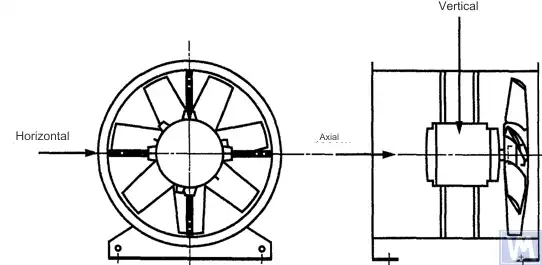
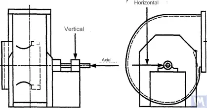
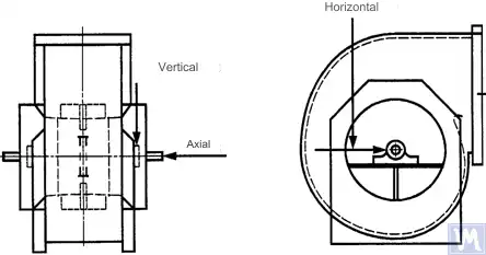
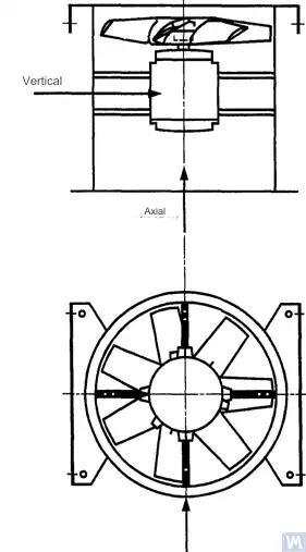
Slike 1 – 4 prikazuju neke moguće mjerne tačke i pravce na svakom ležaju ventilatora. Vrijednosti navedene u tabeli 4 odnose se na mjerenja u pravcu okomitom na osu rotacije. Broj i raspored mjernih tačaka, kako za fabrička ispitivanja tako i za mjerenja na terenu, određuju se prema nahođenju proizvođača ili u dogovoru s kupcem. Preporučuje se mjerenje na ležajevima vratila radnog kola ventilatora (impelera). Ako to nije moguće, senzor treba postaviti na mjesto gdje je osigurana najkraća mehanička veza između njega i ležaja. Senzor se ne smije montirati na neoslonjene panele, kućište ventilatora, elemente ograde ili druga mjesta koja nisu direktno povezana s ležajem (takvi rezultati mjerenja se mogu koristiti, ali ne za procjenu vibracionog stanja ventilatora, već za dobijanje informacija o vibracijama koje se prenose na kanal ili postolje – vidjeti ISO 14695 (GOST 31351) i ISO 5348.
Slika 1. Položaj trokoordinatnog senzora za horizontalno montirani aksijalni ventilator
Slika 2. Položaj trokoordinatnog senzora za radijalni ventilator sa jednim usisom
Slika 3. Položaj trokoordinatnog senzora za radijalni ventilator sa dvostrukim usisom
Slika 4. Položaj trokoordinatnog senzora za vertikalno montirani aksijalni ventilator
Mjerenja u horizontalnom smjeru treba izvršiti pod pravim uglom u odnosu na osu vratila. Mjerenja u vertikalnom smjeru treba izvršiti pod pravim uglom u odnosu na horizontalni smjer mjerenja i okomito na vratilo ventilatora. Mjerenja u longitudinalnom smjeru treba izvršiti paralelno sa osom vratila.
Mjerenja pomoću senzora inercijskog tipa
Sve vrijednosti vibracija navedene u ovom standardu odnose se na mjerenja uzeta pomoću senzora inercijalnog tipa, čiji signal reprodukuje kretanje kućišta ležaja.
Korišteni senzori mogu biti akcelerometri ili senzori brzine. Posebnu pažnju treba posvetiti ispravnom pričvršćivanju senzora: bez zazora na nosivoj površini, bez ljuljanja i rezonanci. Veličina i masa senzora i sistema pričvršćivanja ne smiju biti prevelike kako bi se izbjegle značajne promjene izmjerenih vibracija. Ukupna greška uzrokovana načinom pričvršćivanja senzora i kalibracijom mjernog sistema ne smije premašiti +/- 10% izmjerene vrijednosti.
Mjerenja pomoću beskontaktnih senzora
Dogovorom između korisnika i proizvođača mogu se postaviti zahtjevi za maksimalno dozvoljeno pomjeranje vratila (vidi ISO 7919-1) unutar kliznih ležajeva. Odgovarajuća mjerenja mogu se izvršiti pomoću beskontaktnih senzora.
U ovom slučaju, mjerni sistem određuje pomjeranje površine vratila u odnosu na kućište ležaja. Očigledno je da dozvoljena amplituda pomjeranja ne smije premašiti vrijednost zračnosti u ležaju. Vrijednost zračnosti zavisi od veličine i tipa ležaja, opterećenja (radijalnog ili aksijalnog) i smjera mjerenja (neki dizajni ležajeva imaju eliptičnu rupu, za koju je zračnost u horizontalnom smjeru veća nego u vertikalnom smjeru). Raznovrsnost faktora koje treba uzeti u obzir ne omogućava postavljanje uniformnih granica pomjeranja vratila, ali su neke preporuke date u tabeli 3. Vrijednosti date u ovoj tabeli predstavljaju procenat ukupne vrijednosti radijalne zračnosti u ležaju u svakom smjeru.
Tabela 3 – Maksimalno relativno pomjeranje vratila unutar ležaja
Vibraciono stanje ventilatora
Maksimalno preporučeno pomjeranje, procenat vrijednosti zračnosti (duž bilo koje ose)
Stanje pri puštanju u rad/zadovoljavajuće stanje
Manje od 25%
Upozorenje
+50%
Zaustavljanje
+70%
1) Vrijednosti radijalne i aksijalne zračnosti za specifični ležaj treba dobiti od njegovog dobavljača.
Navedene vrijednosti uzimaju u obzir „lažna“ pomjeranja površine vratila. Ta „lažna“ pomjeranja pojavljuju se u rezultatima mjerenja jer pored vibracija vratila na rezultate utječu i mehanička odstupanja (bacanja) ako je vratilo savijeno ili ima neokrugao oblik. Pri upotrebi beskontaktnog senzora rezultati mjerenja uključuju i električna odstupanja, određena magnetnim i električnim svojstvima materijala vratila u tački mjerenja. Smatra se da tokom puštanja u rad i naknadnog normalnog rada ventilatora raspon zbira mehaničkih i električnih odstupanja u tački mjerenja ne bi trebao premašiti veću od dvije vrijednosti: 0,0125 mm ili 25% izmjerene vrijednosti pomjeranja. Odstupanja se određuju sporim okretanjem vratila (brzinom od 25 do 400 o/min), kada je djelovanje sila uzrokovanih neuravnoteženošću na rotor zanemarivo. Za ispunjenje utvrđene tolerancije odstupanja može biti potrebna dodatna obrada vratila. Beskontaktne senzore, ako je moguće, treba montirati direktno na kućište ležaja.
Navedene granične vrijednosti važe samo za ventilator koji radi u svom nominalnom režimu. Ako dizajn ventilatora omogućava rad sa varijabilnom brzinom rotacije, moguće su više razine vibracija na drugim brzinama zbog neizbježnog uticaja rezonanci.
Ako dizajn ventilatora omogućava promjenu položaja lopatica u odnosu na protok vazduha na usisnom otvoru, navedene vrijednosti treba primijeniti za uslove sa potpuno otvorenim lopaticama. Treba napomenuti da stall protoka vazduha, posebno primjetan pri velikim uglovima lopatica u odnosu na usisni protok vazduha, može dovesti do povećanih razina vibracija.
Nosivi sistem ventilatora
Vibracijsko stanje ventilatora nakon ugradnje određuje se uzimajući u obzir krutost oslonca. Oslonac se smatra krutim ako prva vlastita frekvencija sistema „ventilator – oslonac“ premašuje brzinu rotacije. Obično se pri montaži na velike betonske temelje oslonac može smatrati krutim, a pri montaži na vibroizolatore – podatljivim. Čelični okvir, koji se često koristi za montažu ventilatora, može pripadati bilo kojem od ova dva tipa oslonca. U slučaju sumnje u tip oslonca ventilatora, mogu se provesti proračuni ili ispitivanja radi određivanja prve vlastite frekvencije sistema. U nekim slučajevima oslonac ventilatora treba smatrati krutim u jednom smjeru, a podatljivim u drugom.
Granice dozvoljenih vibracija ventilatora tokom fabričkih testova
Granice nivoa vibracija navedene u tabeli 4 odnose se na sastavljene ventilatore. One se odnose na mjerenja brzine vibracija u uskom pojasu na osloncima ležajeva za frekvenciju rotacije koja se koristi tokom fabričkih testova.
Tabela 4 – Granične vrijednosti vibracija tokom tvorničkih ispitivanja
Kategorija ventilatora
Granična efektivna brzina vibracija, mm/s
Kruti oslonac
Elastični oslonac
BV-1
9.0
11.2
BV-2
3.5
5.6
BV-3
2.8
3.5
BV-4
1.8
2.8
BV-5
1.4
1.8
Napomene
1 Pravila za pretvaranje jedinica brzine vibracije u jedinice pomaka ili ubrzanja za uskopojasne vibracije navedena su u Dodatku A.
2 Vrijednosti u ovoj tabeli odnose se na nazivno opterećenje i nazivnu frekvenciju rotacije ventilatora koji radi u režimu s otvorenim ulaznim lopaticama. Granične vrijednosti za ostale uvjete opterećenja treba dogovoriti između proizvođača i kupca, ali se preporučuje da one ne prelaze tabelarne vrijednosti više od 1,6 puta.
Granice dozvoljenih vibracija ventilatora tokom testiranja na licu mjesta
Vibracije bilo kojeg ventilatora na mjestu rada ne zavise samo od njegovog kvaliteta balansiranja. Faktori vezani za ugradnju, kao što su masa i krutost sistema nosača, također će imati utjecaj. Stoga proizvođač ventilatora nije odgovoran za nivo vibracija ventilatora na mjestu rada osim ako to nije navedeno u ugovoru.
Tabela 5 daje preporučene granične vrijednosti (u jedinicama brzine vibracije za širokopojasne vibracije na kućištima ležajeva) za normalan rad ventilatora u različitim kategorijama.
Tabela 5 – Granične vrijednosti vibracija na mjestu rada
Vibraciono stanje ventilatora
Kategorija ventilatora
Granična efektivna brzina vibracija, mm/s
Kruti oslonac
Elastični oslonac
Puštanje u rad
BV-1
10
11.2
BV-2
5.6
9.0
BV-3
4.5
6.3
BV-4
2.8
4.5
BV-5
1.8
2.8
Upozorenje
BV-1
10.6
14.0
BV-2
9.0
14.0
BV-3
7.1
11.8
BV-4
4.5
7.1
BV-5
4.0
5.6
Zaustavljanje
BV-1
__1)
__1)
BV-2
__1)
__1)
BV-3
9.0
12.5
BV-4
7.1
11.2
BV-5
5.6
7.1
1) Nivo gašenja za ventilatore kategorija BV-1 i BV-2 utvrđuje se na osnovu dugotrajne analize rezultata mjerenja vibracija.
Vibracije novih ventilatora koji se puštaju u rad ne bi trebalo da prelaze nivo „puštanja u rad“. Kako ventilator radi, očekuje se da će se njegov nivo vibracija povećati zbog procesa habanja i kumulativnog efekta faktora koji utiču. Takvo povećanje vibracija je općenito prirodno i ne bi trebalo izazvati zabrinutost dok ne dostigne nivo „upozorenja“.
Po dostizanju nivoa „upozoravajuće“ vibracije, potrebno je istražiti uzroke povećane vibracije i odrediti mjere za njeno smanjenje. Rad ventilatora u ovom stanju treba biti pod stalnim nadzorom i ograničen na vrijeme potrebno za identifikaciju mjera za uklanjanje uzroka povećane vibracije.
Ako nivo vibracija dostigne nivo „isključenja“, odmah se moraju preduzeti mjere za otklanjanje uzroka povećane vibracije, u suprotnom, ventilator treba zaustaviti. Odlaganje dovođenja nivoa vibracija na prihvatljivu razinu može dovesti do oštećenja ležaja, pukotina na rotoru i na mjestima zavarivanja kućišta ventilatora, što u konačnici rezultira uništenjem ventilatora.
Prilikom procjene vibracijskog stanja ventilatora, bitno je pratiti promjene nivoa vibracija tokom vremena. Iznenadna promjena nivoa vibracija ukazuje na potrebu za hitnim mjerama pregleda i održavanja ventilatora. Prilikom praćenja promjena vibracija, prijelazne procese uzrokovane, na primjer, zamjenom maziva ili postupcima održavanja ne treba uzeti u obzir.
Uticaj postupka montaže
Osim radnih kola, ventilatori uključuju i druge rotirajuće elemente koji mogu uticati na nivo vibracija ventilatora: pogonske remenice, remenje, spojnice, rotore motora ili druge pogonske uređaje. Ako uvjeti narudžbe zahtijevaju isporuku ventilatora bez pogonskog uređaja, može biti nepraktično da proizvođač provodi testove sklopa kako bi odredio nivoe vibracija. U tom slučaju, čak i ako je proizvođač izbalansirao radno kolo ventilatora, nema sigurnosti da će ventilator raditi nesmetano dok se vratilo ventilatora ne spoji na pogon i cijela mašina se testira na vibracije tokom puštanja u rad.
Obično, nakon montaže, potrebno je dodatno balansiranje kako bi se nivo vibracija smanjio na prihvatljiv nivo. Za sve nove ventilatore kategorija BV-3, BV-4 i BV-5 preporuča se mjerenje vibracija montirane mašine prije puštanja u rad. Ovo će uspostaviti osnovnu liniju i odrediti dalje mjere održavanja.
Proizvođači ventilatora nisu odgovorni za utjecaj na vibracije dijelova pogona instaliranih nakon tvorničkog testiranja.
Alati za mjerenje vibracija i kalibracija
Mjerni alati
Korišteni mjerni alati i mašine za balansiranje moraju biti verificirani i ispunjavati zahtjeve zadatka. Interval između verifikacija određen je preporukama proizvođača za mjerne (testne) alate. Stanje mjernih alata mora osigurati njihov normalan rad tokom cijelog perioda testiranja.
Osoblje koje radi sa mjernim alatima mora imati dovoljno vještina i iskustva da otkrije potencijalne kvarove i pogoršanje kvaliteta mjernih alata.
Kalibracija
Svi mjerni alati moraju biti kalibrirani u skladu sa standardima. Složenost postupka kalibracije može varirati od jednostavne fizičke inspekcije do kalibracije cijelog sistema. Korektivne mase koje se koriste za određivanje preostale neravnoteže prema ISO 1940-1 mogu se koristiti i za kalibraciju mjernih alata.
Dokumentacija
Balansiranje
Na zahtjev, ako je predviđeno uslovima ugovora, korisniku se može dostaviti izvještaj o ispitivanju balansiranja ventilatora, koji se preporučuje da sadrži sljedeće informacije: – Naziv proizvođača mašine za balansiranje, broj modela; – Vrsta ugradnje rotora: između nosača ili konzolno; – Metoda balansiranja: statička ili dinamička; – Masa rotirajućih delova sklopa rotora; – Rezidualnog neuravnoteženja u svakom korekcijske ravnine (koristite naš kalkulator rezidualnog disbalansa (ISO 21940-11) za utvrđivanje dozvoljenih vrijednosti); – Dozvoljena rezidualna neravnoteža u svakoj ravni korekcije; – Klasa tačnosti balansiranja; – Kriterijumi prihvatanja: prihvaćeno/odbijeno; – Potvrda o balansiranju (ako je potrebno).
Vibracija
Na zahtjev, ako je predviđeno uslovima ugovora, kupcu se može dostaviti izvještaj o testiranju vibracija ventilatora, koji se preporučuje da sadrži sljedeće informacije: – Korišteni mjerni alati; – Način pričvršćivanja senzora vibracija; – Radni parametri ventilatora (protok vazduha, pritisak, snaga); – Frekvencija rotacije ventilatora; – Vrsta oslonca: krut ili podatljiv; – Izmjerene vibracije: 1) Položaji senzora vibracija i mjerne ose, 2) mjerne jedinice i referentni nivoi vibracija, 3) opseg frekvencija mjerenja (uski ili široki frekvencijski opseg); – Dozvoljeni nivo(i) vibracija; – Izmjereni nivo(i) vibracija; – Kriterijumi prihvatanja: prihvaćeno/odbijeno; – Certifikat o nivou vibracija (ako je potrebno).
METODE BALANSIRANJA VENTILATORA NA MAŠINI ZA BALANSIRANJE
B.1. Ventilator s direktnim pogonom
B.1.1. Opće odredbe
Radno kolo ventilatora, koje se tokom sastavljanja montira direktno na vratilo motora, treba balansirati prema istom pravilu za uzimanje u obzir uticaja utora za klin kao i za vratilo motora.
Motori iz ranijih godina proizvodnje mogli su biti balansirani upotrebom pune žlijebne veze (keyway). Trenutno se vratila motora balansiraju upotrebom polužlijebne veze (half-keyway), kako je propisano standardom ISO 8821 (usvojen kao GOST 31322), i označavaju se slovom H (vidjeti ISO 8821).
B.1.2. Motori balansirani sa punim utorom za klin
Radno kolo ventilatora, montirano na vratilo motora balansirano sa punim utorom za klin, treba balansirati bez klina na konusnom vratilu.
B.1.3. Motori balansirani sa polovinom utora za klin
Za radno kolo ventilatora montirano na vratilo motora balansirano sa polovinom utora za klin, moguće su sljedeće opcije: a) ako kolo ima čeličnu glavčinu, izrežite utor za klin u njoj nakon balansiranja; b) balansirajte na konusnom trnu s polovinom klina umetnutom u utor za klin; c) balansirajte na trnu s jednim ili više utora za klin (vidi B.3), koristeći pune klinove.
B.2. Ventilatori koje pogoni drugo vratilo
Gdje je moguće, svi rotirajući elementi, uključujući vratilo ventilatora i remenicu, trebali bi se balansirati kao jedinstvena cjelina. Ako to nije praktično, balansiranje treba izvesti na trnu (vidi B.3) koristeći isto pravilo za uzimanje u obzir utora za klin kao i za vratilo.
B.3. Trn
Vratilo na koje se radno kolo ventilatora montira tokom balansiranja mora zadovoljiti sljedeće zahtjeve: a) biti što lakši; b) biti u uravnoteženom stanju, osiguranom odgovarajućim održavanjem i redovnim pregledima; c) po mogućnosti biti konusan kako bi se smanjile greške povezane s ekscentričnošću, koje proizlaze iz tolerancija otvora glavčine i dimenzija trna. Ako je trn konusan, pravi položaj korekcijskih ravni u odnosu na ležajeve treba uzeti u obzir u proračunima neuravnoteženosti.
Ako je potrebno koristiti cilindrično vratilo, ono treba imati izrezan utor za klin, u koji se umetne puni klin za prijenos obrtnog momenta sa vratila na radno kolo ventilatora.
Druga opcija je izrezati dva utora za klin na suprotnim krajevima promjera vratila, što omogućava korištenje metode obrnutog balansiranja. Ova metoda uključuje sljedeće korake. Prvo, izmjerite neuravnoteženost kola umetanjem punog klina u jedan utor, a polovine klina u drugi. Zatim rotirajte kolo za 180° u odnosu na trn i ponovo izmjerite njegovu neuravnoteženost. Razlika između dvije vrijednosti neuravnoteženosti posljedica je preostale neuravnoteženosti trna i univerzalnog zgloba pogona. Da biste dobili pravu vrijednost neuravnoteženosti rotora, uzmite polovinu razlike ova dva mjerenja.
IZVORI VIBRACIJA VENTILATORA
Unutar ventilatora postoji mnogo izvora vibracija, a vibracije na određenim frekvencijama mogu se direktno povezati sa specifičnim konstrukcijskim karakteristikama mašine. Ovaj dodatak obuhvata samo najčešće izvore vibracija uočene kod većine tipova ventilatora. Opće pravilo je da svako olabavljenje u nosivom sistemu uzrokuje pogoršanje vibracionog stanja ventilatora.
Neuravnoteženost ventilatora
Ovo je primarni izvor vibracija ventilatora; karakterizira ga prisutnost komponente vibracija na frekvenciji rotacije (prva harmonik). Uzrok neuravnoteženja je što je os rotirajuće mase ekscentrična ili nagnuta prema osi rotacije. To može biti uzrokovano nejednolikom raspodjelom mase, zbrajanjem tolerancija na dimenzijama rupe glavčine i vratila, savijanjem vratila, ili kombinacijom tih čimbenika. Vibracije uzrokovane neuravnoteženjem djeluju uglavnom u radijalnom smjeru.
Privremeno savijanje vratila može nastati zbog neravnomjernog mehaničkog zagrijavanja – usljed trenja između rotirajućih i nepokretnih elemenata – ili zbog električne prirode. Trajno savijanje može nastati zbog promjene svojstava materijala ili nesaosnosti vratila i radnog kola kada su ventilator i motor montirani odvojeno.
Tokom rada, neuravnoteženost radnog kola ventilatora može se povećati zbog taloženja čestica iz zraka. Kada radi u agresivnom okruženju, neuravnoteženost može nastati zbog nejednake erozije ili korozije točka.
Neuravnoteženost se može ispraviti dodatnim balansiranjem u odgovarajućim ravnima, ali prije izvođenja postupka balansiranja treba utvrditi i otkloniti izvore neuravnoteženosti te provjeriti vibracijsku stabilnost mašine.
Nesaosnost ventilatora i motora
Ova mana se može pojaviti kada su vratila motora i ventilatora povezana preko kaišnog pogona ili fleksibilne spojke. Nesaosnost se ponekad može prepoznati po karakterističnim komponentama frekvencije vibracija, obično prvom i drugom harmoniku frekvencije rotacije. U slučaju paralelne nesaosnosti vratila, vibracije se prvenstveno javljaju u radijalnom smjeru, dok se, ako se vratila sijeku pod uglom, longitudinalne vibracije mogu učiniti dominantnim.
Ako su vratila povezana pod uglom i koriste se krute spojke, u mašini počinju djelovati naizmjenične sile, što uzrokuje povećano habanje vratila i spojki. Ovaj efekat se može značajno smanjiti korištenjem fleksibilnih spojki.
Pobudu vibracija može uzrokovati interakcija rotora ventilatora sa stacionarnim elementima konstrukcije, kao što su vodiće lopatice, motor ili oslonci ležajeva, nepravilne vrijednosti zazora, ili neodgovarajuće projektirana struktura usisa i ispuha. Karakteristična svojstva tih izvora su pojava periodičnih vibracija povezanih s frekvencijom rotacije rotora, na pozadini slučajnih fluktuacija u interakciji lopatica rotora sa zrakom. Vibracije se mogu promatrati na harmonicima frekvencije lopatice, što je proizvod frekvencije rotacije rotora i broja lopatica rotora.
Aerodinamička nestabilnost strujanja zraka, uzrokovana njegovim odvajanjem od površine lopatice i naknadnim stvaranjem vrtloga, izaziva širokopojasne vibracije, čiji se oblik spektra mijenja ovisno o opterećenju ventilatora.
Aerodinamički zvuk karakterizira to što nije povezan s frekvencijom rotacije kola i može se javiti na subharmonicima frekvencije rotacije (tj. na frekvencijama ispod frekvencije rotacije). U tom slučaju mogu se uočiti značajne vibracije kućišta ventilatora i kanala.
Ako je aerodinamički sistem ventilatora loše usklađen sa njegovim karakteristikama, u njemu se mogu javiti oštri udari. Ovi udari se lako razlikuju sluhom i prenose se kao impulsi na nosivi sistem ventilatora.
Ako gore navedeni uzroci dovedu do vibracija lopatica, njihova priroda se može istražiti instaliranjem senzora u različite dijelove konstrukcije.
Vibracije ventilatora uslijed vrtloženja u uljnom sloju
Vrtlozi koji se mogu javiti u sloju maziva kliznih ležajeva uočavaju se na karakterističnoj frekvenciji nešto nižoj od frekvencije obrtanja rotora, osim ako ventilator radi na brzini većoj od prve kritične. U potonjem slučaju nestabilnost uljnog klina uočava se na prvoj kritičnoj brzini, a ovaj efekat se ponekad naziva rezonantni vrtlog.
Izvori vibracija ventilatora električne prirode
Nejednako zagrijavanje rotora motora može uzrokovati njegovo savijanje, što dovodi do neuravnoteženosti (manifestira se na prvom harmoniku).
U slučaju asinhronog motora, prisustvo komponente na frekvenciji jednako frekvenciji rotacije pomnoženoj sa brojem ploča rotora ukazuje na mane povezane sa pločama statora, i obrnuto, komponente na frekvenciji jednako frekvenciji rotacije pomnoženoj sa brojem ploča rotora ukazuju na mane povezane sa pločama rotora.
Mnoge komponente vibracija električne prirode karakteriše njihovo trenutno nestajanje kada se isključi napajanje.
Općenito, postoje dvije vrste problema vezanih za kaišne pogone: kada na rad pogona utiču vanjski defekti i kada su defekti u samom kaišu.
U prvom slučaju, iako kaiš vibrira, to je zbog prisilnih sila iz drugih izvora, tako da zamjena kaiša neće dati željene rezultate. Česti izvori takvih sila su neuravnoteženost u pogonskom sistemu, ekscentričnost remenice, nesaosnost i olabavljeni mehanički spojevi. Stoga, prije zamjene kaiševa, treba izvesti analizu vibracija kako bi se utvrdio izvor uzbude.
Ako kaiševi reagiraju na vanjske prisilne sile, frekvencija njihovih vibracija će najvjerovatnije biti jednaka frekvenciji uzbude. U tom slučaju, frekvencija uzbude može se odrediti pomoću stroboskopske lampe, podešavanjem tako da kaiš u svjetlu lampe djeluje nepomično.
U slučaju višekaišnog pogona, nejednako zatezanje kaiševa može dovesti do značajnog povećanja prenesenih vibracija.
Slučajevi u kojima su izvori vibracija sami remeni povezani su s njihovim fizičkim defektima: pukotinama, tvrdim i mekim mjestima, prljavštinom na površini remena, nedostajućim materijalom na njegovoj površini itd. Kod klinastih remena promjene njihove širine uzrokovat će da remen izlazi i ulazi u žlijeb remenice, stvarajući vibracije zbog promjene njegovog zatezanja.
Ako je izvor vibracija sam kaiš, frekvencije vibracija su obično harmonici frekvencije rotacije kaiša. U konkretnom slučaju, frekvencija uzbude zavisit će od prirode defekta i broja remenica, uključujući zatezače.
U nekim slučajevima, amplituda vibracija može biti nestabilna. Ovo je posebno slučaj za višekaišne pogone.
Mehaničke i električne mane su izvori vibracija, koji se zatim pretvaraju u zračni zvuk. Mehanički zvuk može biti povezan sa neuravnotežnošću ventilatora ili motora, bukom ležaja, centriranjem osi, vibracijama zidova kanala i panela kućišta, vibracijama lopatica prigušivača, vibracijama lopatica, prigušivača, cijevi i nosača, kao i prijenosom mehaničkih vibracija kroz konstrukciju. Električni zvuk je povezan sa različitim oblicima pretvorbe električne energije: 1) Magnetne sile određene su gustinom magnetskog fluksa, brojem i oblikom polova i geometrijom zračnog jaza; 2) Nasumični električni zvuk određen je četkicama, lukovima, električnim iskrama itd.
Aerodinamički zvuk može biti povezan sa stvaranjem vrtloga, pulsacijama pritiska, otporom zraka itd. i može imati širokopojasnu i uskopojasnu prirodu. Širokopojasni zvuk može biti uzrokovan: a) lopaticama, prigušivačima i drugim preprekama u putu protoka zraka; b) rotacijom ventilatora kao cjeline, kaiševima, pukotinama itd.; c) naglim promjenama smjera protoka zraka ili poprečnog presjeka kanala, razlikama u brzinama protoka, odvajanjem protoka zbog graničnih efekata, efektima kompresije protoka itd. Uskopojasni zvuk može biti uzrokovan: a) rezonancama (efekt orguljske cijevi, vibracije žica, vibracije panela, strukturnih elemenata itd.); b) stvaranjem vrtloga na oštrim ivicama (uzbuda stuba zraka); c) rotacijama (efekt sirene, pukotine, rupe, utori na rotirajućim dijelovima).
Udarci nastali kontaktom između različitih mehaničkih elemenata konstrukcije proizvode buku sličnu onoj koju stvaraju udarci čekića, udar groma, rezonantna prazna kutija, itd. Zvukovi udara mogu se čuti od udaraca zubaca zupčanika i od lupanja neispravnog remena. Impulsi udara mogu biti toliko prolazni da je za razlikovanje periodičnih udarnih impulsa od prolaznih procesa potrebna posebna oprema za snimanje velike brzine. U području u kojem se javljaju mnogi udarni impulsi, superponiranje njihovih vrhova stvara efekat konstantnog brujanja.
Ovisnost vibracija o vrsti nosača ventilatora
Pravilan izbor nosača ventilatora ili dizajna temelja neophodan je za njegov nesmetan rad bez problema. Da bi se osiguralo poravnanje rotirajućih komponenti prilikom ugradnje ventilatora, motora i drugih pogonskih uređaja, koristi se čelični okvir ili armirano-betonska baza. Ponekad pokušaj uštede na potpornoj konstrukciji dovodi do nemogućnosti održavanja potrebnog poravnanja komponenti mašine. Ovo je posebno neprihvatljivo kada su vibracije osjetljive na promjene poravnanja, posebno za mašine koje se sastoje od zasebnih dijelova povezanih metalnim spojnim elementima.
Na vibracije ventilatora i motora može uticati i temelj na koji se postavlja podloga. Ako je prirodna frekvencija temelja bliska frekvenciji rotacije ventilatora ili motora, temelj će rezonirati tokom rada ventilatora. Ovo se može otkriti mjerenjem vibracija na nekoliko tačaka na temelju, okolnom podu i nosačima ventilatora. Često u uslovima rezonancije, vertikalna komponenta vibracije značajno premašuje horizontalnu. Vibracije se mogu ublažiti tako da temelj postane čvršći ili da mu se poveća masa. Čak i ako se neuravnoteženost i nesaosnost eliminišu, što omogućava smanjenje prisilnih sila, još uvijek mogu postojati značajni preduslovi za vibracije. To znači da ako je ventilator, zajedno sa svojim nosačem, blizu rezonancije, postizanje prihvatljivih vrijednosti vibracija će zahtijevati preciznije balansiranje i preciznije poravnanje vratila nego što je uobičajeno za takve mašine. Ova situacija je nepoželjna i treba je izbjeći povećanjem mase i/ili krutosti nosača ili betonskog bloka.
Vodič za praćenje i dijagnostiku stanja vibracija
Glavni princip praćenja stanja vibracija mašine (u daljem tekstu stanje) je posmatranje rezultata pravilno planiranih mjerenja kako bi se identifikovao trend povećanja nivoa vibracija i sagledao iz perspektive potencijalnih problema. Monitoring je primjenjiv u situacijama kada se oštećenje sporo razvija, a pogoršanje stanja mehanizma se manifestuje kroz mjerljive fizičke znakove.
Vibracije ventilatora, koje nastaju kao rezultat razvoja fizičkih defekata, mogu se pratiti u određenim intervalima, a kada se detektuje povećanje nivoa vibracija, može se povećati frekvencija posmatranja i izvršiti detaljna analiza stanja. U ovom slučaju, uzroci promjena vibracija mogu se identificirati na osnovu analize frekvencije vibracija, koja omogućava određivanje potrebnih mjera i planiranje njihove provedbe mnogo prije nego što šteta postane velika. Obično se mjere smatraju neophodnim kada se nivo vibracija poveća za 1,6 puta ili za 4 dB u odnosu na osnovni nivo.
Program praćenja stanja sastoji se od nekoliko faza, koje se mogu ukratko formulirati na sljedeći način:
a) identifikovati stanje ventilatora i odrediti osnovni nivo vibracija (može se razlikovati od nivoa dobijenog tokom fabričkih ispitivanja zbog različitih metoda ugradnje, itd.);
b) odabrati tačke mjerenja vibracija;
c) odrediti frekvenciju posmatranja (mjerenja);
d) uspostaviti postupak registracije informacija;
e) odrediti kriterijume za procenu vibracionog stanja ventilatora, granične vrednosti za apsolutne vibracije i promene vibracija, sumirati iskustvo rada sa sličnim mašinama.
Budući da ventilatori obično rade bez problema pri brzinama koje se ne približavaju kritičnoj, nivo vibracija se ne bi trebao značajno mijenjati s malim promjenama brzine ili opterećenja, ali je važno napomenuti da kada ventilator radi s promjenjivom brzinom rotacije, utvrđene granične vrijednosti vibracija vrijede za maksimalnu radnu brzinu rotacije. Ako se maksimalna brzina rotacije ne može postići unutar utvrđene granice vibracija, to može ukazivati na prisustvo ozbiljnog problema i zahtijevati posebnu istragu.
Neke dijagnostičke preporuke date u Dodatku C zasnovane su na iskustvu rada ventilatora i namijenjene su sekvencijalnoj primjeni prilikom analize uzroka povećane vibracije.
Za kvalitativnu procjenu vibracija određenog ventilatora i utvrđivanje smjernica za daljnje radnje, mogu se koristiti granice zone uvjeta vibracija utvrđene ISO 10816-1.
Očekuje se da će za nove ventilatore nivoi vibracija biti ispod graničnih vrijednosti datih u tabeli 3. Ove vrijednosti odgovaraju granici zone A stanja vibracija prema ISO 10816-1. Preporučene vrijednosti za nivoe upozorenja i isključenja utvrđuju se na osnovu analize prikupljenih informacija o određenim tipovima ventilatora.
INFORMACIJE O USKLAĐENOSTI
REFERENTNI MEĐUNARODNI STANDARDI KOJI SE KAO NORMATIVNE REFERENCE U OVOM STANDARDU
Tabela H.1
Oznaka referentnog međudržavnog standarda
Oznaka i naziv referentnog međunarodnog standarda i uslovna oznaka njegovog stepena usklađenosti sa referentnim međudržavnim standardom
GOST ISO 1940-1-2007
ISO 1940-1:1986. Vibracije. Zahtjevi za kvalitetu balansiranja krutih rotora. Dio 1. Određivanje dozvoljene neravnoteže (IDT)
GOST ISO 5348-2002
ISO 5348:1999. Vibracije i udarci. Mehanička montaža akcelerometara (IDT)
GOST ISO 7919-1-2002
ISO 7919-1:1996. Vibracije neklipnih mašina. Mjerenja na rotirajućim vratilima i kriteriji za ocjenjivanje. Dio 1. Opće smjernice (IDT)
GOST ISO 10816-1-97
ISO 10816-1:1995. Vibracije. Procjena stanja mašine mjerenjem vibracija na nerotirajućim dijelovima. Dio 1. Opće smjernice (IDT)
GOST ISO 10816-3-2002
ISO 10816-3:1998. Vibracije. Procjena stanja mašine mjerenjem vibracija na nerotirajućim dijelovima. Dio 3. Industrijske mašine sa nazivnom snagom većom od 15 kW i nazivnom brzinom od 120 do 15000 o/min, mjerenja na licu mjesta (IDT)
GOST 10921-90
ISO 5801:1997. Industrijski ventilatori. Testiranje performansi korištenjem standardiziranih kanala (NEQ)
GOST 19534-74
ISO 1925:2001. Vibracije. Balansiranje. Rječnik (NEQ)
GOST 24346-80
ISO 2041:1990. Vibracije i udarci. Rječnik (NEQ)
GOST 31322-2006 (ISO 8821:1989)
ISO 8821:1989. Vibracije. Balansiranje. Smjernice za obračunavanje efekta klina kod balansiranja vratila i ugrađenih dijelova (MOD)
GOST 31351-2007 (ISO 14695:2003)
ISO 14695:2003. Industrijski ventilatori. Metode mjerenja vibracija (MOD)
Napomena: U ovoj tabeli se koriste sljedeće uslovne oznake stepena usklađenosti standarda: IDT – identični standardi;
Nikolai Shelkovenko je inženjer analize vibracija te osnivač i izvršni direktor kompanije Vibromera.
Više od 15 godina balansira rotacionu opremu na terenu, a ne na ispitnom stolu: malčere, industrijske ventilatore, drobilice, centrifuge, vratila i vretena. Upravo je iz tog rada nastala serija instrumenata Balanset — osmišljeni su kao alat koji stručnjak može ponijeti do mašine i njime raditi sam, na licu mjesta, a ne kao laboratorijska oprema.
Vibromera je osnovana 2017. godine, a od 2023. sjedište joj je u Portu u Portugalu. Ovdje se odvijaju razvoj, sklapanje i podrška za liniju Balanset. Vodeći instrument je Balanset-1A, prijenosni analizator za balansiranje u jednoj i dvije ravni te za vibracijsku dijagnostiku.
Nikolai lično učestvuje u podršci korisnicima, u rješavanju složenih slučajeva balansiranja i u razvoju softvera. Radi s korisnicima širom svijeta, na bilo kojem jeziku.



0 Comments