
पोर्टेबल बैलेंसर ""बैलेंसेट-1ए""
एक दोहरे चैनल पीसी-आधारित गतिशील संतुलन प्रणाली
संचालन पुस्तिका
संशोधित 1.56 मई 2023
२०२३ | एस्टोनिया, नारवा
सुरक्षा सूचना: यह उपकरण यूरोपीय संघ के सुरक्षा मानकों का अनुपालन करता है। यह श्रेणी 2 लेज़र उत्पाद है। घूर्णन उपकरण सुरक्षा प्रक्रियाओं का पालन करें। नीचे पूरी सुरक्षा जानकारी देखें →
1. संतुलन प्रणाली अवलोकन
बैलेन्सेट-1ए बैलेंसर पंखों, पीसने वाले पहियों, तकुओं, क्रशरों, पंपों और अन्य घूर्णन मशीनरी के लिए एकल और दो-तल गतिशील संतुलन सेवाएं प्रदान करता है।
Balanset-1A बैलेंसर में दो वाइब्रोसेंसर (एक्सेलेरोमीटर), लेजर फेज सेंसर (टैकोमीटर), प्री-एम्पलीफायर, इंटीग्रेटर और ADC एक्विजिशन मॉड्यूल के साथ 2-चैनल USB इंटरफेस यूनिट और विंडोज आधारित बैलेंसिंग सॉफ्टवेयर शामिल हैं। Balanset-1A के लिए नोटबुक या अन्य विंडोज (WinXP...Win11, 32 या 64 बिट) संगत पीसी की आवश्यकता होती है।
संतुलन सॉफ्टवेयर एकल-तल और दो-तल संतुलन के लिए स्वचालित रूप से सही संतुलन समाधान प्रदान करता है। Balanset-1A गैर-कंपन विशेषज्ञों के लिए उपयोग करना सरल है।
सभी संतुलन परिणाम संग्रह में सहेजे जाते हैं और रिपोर्ट बनाने के लिए उपयोग किए जा सकते हैं।
प्रमुख विशेषताऐं
प्रयोग करने में आसान
- • उपयोगकर्ता द्वारा चयनित परीक्षण द्रव्यमान
- • परीक्षण की सामूहिक वैधता का पॉपअप
- • मैन्युअल डेटा इनपुट
मापन क्षमताएँ
- • आरपीएम, आयाम और चरण
- • FFT स्पेक्ट्रम विश्लेषण
- • तरंगरूप और स्पेक्ट्रम प्रदर्शन
- • दोहरे चैनल पर एक साथ डेटा
उन्नत कार्य
- • सहेजे गए प्रभाव गुणांक
- • ट्रिम बैलेंसिंग
- • मैंड्रेल उत्केंद्रता गणना।
- • आईएसओ 1940 सहनशीलता गणना।
डेटा प्रबंधन
- • असीमित बैलेंसिंग डेटा स्टोरेज
- • कंपन तरंगरूप भंडारण
- • अभिलेख और रिपोर्ट
गणना उपकरण
- • विभाजित वजन गणना
- • ड्रिल गणना
- • सुधार तलों को बदलना
- • ध्रुवीय ग्राफ दृश्यीकरण
विश्लेषण विकल्प
- • परीक्षण भार हटा दें या वहीं छोड़ दें
- • रनडाउन चार्ट (प्रायोगिक)
2. विशिष्टता
| पैरामीटर | विनिर्देश |
|---|---|
| कंपन वेग के मूल-माध्य-वर्ग मान (RMS) की माप सीमा, मिमी/सेकंड (1x कंपन के लिए) | from 0.2 to 80 |
| कंपन वेग के RMS माप की आवृत्ति रेंज, हर्ट्ज | from 5 to 1000 (amplitude error ≤10% from 5 to 550 Hz; up to 20% from 550 to 1000 Hz) |
| सुधार विमानों की संख्या | 1 और 2 |
| घूर्णन आवृत्ति माप की सीमा, आरपीएम | 250 – 90000 |
| कंपन चरण माप की सीमा, कोणीय डिग्री | 0 से 360 तक |
| कंपन चरण माप की त्रुटि, कोणीय डिग्री | ± १ |
| RMS कंपन वेग की माप सटीकता | ±(0.1 + 0.1×वीमापा) मिमी/सेकंड |
| घूर्णन आवृत्ति की माप सटीकता | ±(1 + 0.005×एनमापा) आरपीएम |
| विफलताओं के बीच औसत समय (एमटीबीएफ), घंटे, मिनट | 1000 |
| औसत सेवा जीवन, वर्ष, न्यूनतम | 6 |
| आयाम (हार्ड केस में), सेमी | 39*33*13 |
| द्रव्यमान, किग्रा | पाँच से कम |
| वाइब्रेटर सेंसर के समग्र आयाम, मिमी, अधिकतम | 25*25*20 |
| वाइब्रेटर सेंसर का द्रव्यमान, किग्रा, अधिकतम | 0.04 |
|
परिचालन की स्थिति: तापमान सीमा: 5°C से 50°C तक - सापेक्ष आर्द्रता: < 85%, असंतृप्त - बिना प्रबल विद्युत-चुंबकीय क्षेत्र और प्रबल प्रभाव के |
|
3. पैकेज
बैलेंसेट-1ए बैलेंसर में दो एकल-अक्ष एक्सेलेरोमीटर, लेजर फेज रेफरेंस मार्कर (डिजिटल टैकोमीटर), प्री-एम्पलीफायर्स के साथ 2-चैनल यूएसबी इंटरफेस यूनिट, इंटीग्रेटर्स और एडीसी अधिग्रहण मॉड्यूल और विंडोज आधारित बैलेंसिंग सॉफ्टवेयर शामिल हैं।
डिलीवरी सेट
| विवरण | संख्या | टिप्पणी |
|---|---|---|
| यूएसबी इंटरफ़ेस इकाई | 1 | |
| लेजर चरण संदर्भ मार्कर (टैकोमीटर) | 1 | |
| एकल-अक्ष एक्सेलेरोमीटर | 2 | |
| चुंबकीय स्टैंड | 1 | |
| डिजिटल तराजू | 1 | |
| परिवहन के लिए कठिन मामला | 1 | |
| ""बैलेंससेट-1ए". उपयोगकर्ता पुस्तिका। | 1 | |
| संतुलन सॉफ्टवेयर के साथ फ्लैश डिस्क | 1 |
४. संतुलन सिद्धांत
4.1. ""बैलेंससेट-1ए" में (चित्र 4.1) यूएसबी इंटरफेस यूनिट शामिल है। (1), दो एक्सेलेरोमीटर (2) and (3), चरण संदर्भ मार्कर (4) और पोर्टेबल पीसी (आपूर्ति नहीं की गई) (5).
डिलीवरी सेट में चुंबकीय स्टैंड भी शामिल है (6) चरण संदर्भ मार्कर और डिजिटल स्केल को माउंट करने के लिए उपयोग किया जाता है 7.
X1 और X2 कनेक्टर्स का उपयोग क्रमशः वाइब्रेशन सेंसरों को 1 और 2 माप चैनलों से जोड़ने के लिए किया जाता है, और X3 कनेक्टर का उपयोग फेज रेफरेंस मार्कर को जोड़ने के लिए किया जाता है।
यूएसबी केबल पावर सप्लाई और कंप्यूटर से यूएसबी इंटरफ़ेस इकाई के कनेक्शन को प्रदान करता है।

चित्र 4.1. "बैलेंसेट-1ए" का डिलीवरी सेट"
यांत्रिक कंपन कंपन संवेदक के आउटपुट पर कंपन त्वरण के समानुपाती विद्युत संकेत उत्पन्न करते हैं। ADC मॉड्यूल से डिजिटल सिग्नल USB के माध्यम से पोर्टेबल PC में स्थानांतरित किए जाते हैं। (5). चरण संदर्भ चिह्नक, घूर्णन आवृत्ति और कंपन चरण कोण की गणना के लिए प्रयुक्त स्पंद संकेत उत्पन्न करता है। विंडोज़ आधारित सॉफ़्टवेयर एकल-तल और द्वि-तल संतुलन, स्पेक्ट्रम विश्लेषण, चार्ट, रिपोर्ट और प्रभाव गुणांकों के संग्रहण हेतु समाधान प्रदान करता है।
5. सुरक्षा सावधानियाँ
⚡ ध्यान दें - विद्युत सुरक्षा
5.1. 220V पर काम करते समय विद्युत सुरक्षा नियमों का पालन करना अनिवार्य है। 220V से जुड़े होने पर उपकरण की मरम्मत की अनुमति नहीं है।
5.2. यदि आप कम गुणवत्ता वाली एसी बिजली आपूर्ति वाले वातावरण में या नेटवर्क व्यवधान की उपस्थिति में उपकरण का उपयोग करते हैं, तो कंप्यूटर के बैटरी पैक से स्टैंडअलोन बिजली का उपयोग करने की सलाह दी जाती है।
⚠️ घूर्णनशील उपकरणों के लिए अतिरिक्त सुरक्षा आवश्यकताएँ
- !मशीन लॉकआउट: सेंसर स्थापित करने से पहले हमेशा उचित लॉकआउट/टैगआउट प्रक्रियाओं को लागू करें
- !व्यक्तिगत सुरक्षा उपकरण: सुरक्षा चश्मा और श्रवण सुरक्षा उपकरण पहनें, तथा घूमती हुई मशीनरी के पास ढीले कपड़े पहनने से बचें
- !सुरक्षित स्थापना: सुनिश्चित करें कि सभी सेंसर और केबल सुरक्षित रूप से लगे हुए हैं और घूमते हुए भागों में फंस नहीं सकते
- !आपातकालीन कार्यवाही: आपातकालीन स्टॉप और शटडाउन प्रक्रियाओं का स्थान जानें
- !प्रशिक्षण: केवल प्रशिक्षित कर्मियों को ही घूर्णनशील मशीनरी पर संतुलन उपकरण संचालित करना चाहिए
6. सॉफ्टवेयर और हार्डवेयर सेटिंग्स
6.1. यूएसबी ड्राइवर और बैलेंसिंग सॉफ़्टवेयर इंस्टॉलेशन
काम शुरू करने से पहले ड्राइवर और बैलेंसिंग सॉफ़्टवेयर इंस्टॉल करें।
फ़ोल्डरों और फ़ाइलों की सूची
इंस्टॉलेशन डिस्क (फ्लैश ड्राइव) में निम्नलिखित फ़ाइलें और फ़ोल्डर शामिल हैं:
- बीएस1एवी###सेटअप – "Balanset-1A" बैलेंसिंग सॉफ़्टवेयर वाला फ़ोल्डर (संस्करण संख्या #)
- आर्डड्राइव – यूएसबी ड्राइवर
- ई-बैलेन्सर_मैनुअल.पीडीएफ – यह मैनुअल
- Bal1Av###सेटअप.exe – सेटअप फ़ाइल। इस फ़ाइल में ऊपर उल्लिखित सभी संग्रहित फ़ाइलें और फ़ोल्डर शामिल हैं। ### – "Balanset-1A" सॉफ़्टवेयर का संस्करण।
- इबैलेंस.सीएफजी – संवेदनशीलता मान
- बाल.िनी – कुछ आरंभीकरण डेटा
सॉफ़्टवेयर स्थापना प्रक्रिया
ड्राइवर और विशेष सॉफ़्टवेयर इंस्टॉल करने के लिए फ़ाइल चलाएँ। Bal1Av###सेटअप.exe और बटन दबाकर सेटअप निर्देशों का पालन करें «अगला», «ОКआदि
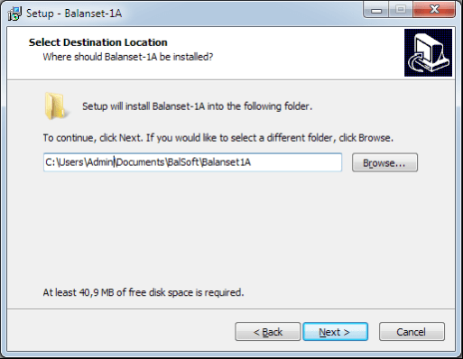
सेटअप फ़ोल्डर चुनें। आमतौर पर दिए गए फ़ोल्डर को नहीं बदलना चाहिए।
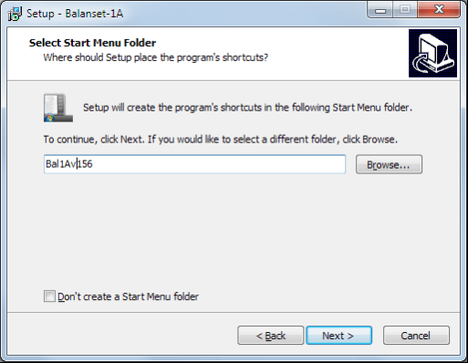
फिर प्रोग्राम को प्रोग्राम समूह और डेस्कटॉप फ़ोल्डरों को निर्दिष्ट करने की आवश्यकता होती है। बटन दबाएँ। अगला.
स्थापना को अंतिम रूप देना
- ✓निरीक्षित या संतुलित तंत्र पर सेंसर स्थापित करें (सेंसर स्थापित करने के तरीके के बारे में विस्तृत जानकारी परिशिष्ट 1 में दी गई है)
- ✓वाइब्रेशन सेंसर 2 और 3 को इनपुट X1 और X2 से कनेक्ट करें, और फेज एंगल सेंसर को USB इंटरफ़ेस यूनिट के इनपुट X3 से कनेक्ट करें।
- ✓कंप्यूटर के यूएसबी पोर्ट से यूएसबी इंटरफ़ेस यूनिट को कनेक्ट करें।
- ✓एसी पावर सप्लाई का इस्तेमाल करते समय, कंप्यूटर को पावर मेन्स से कनेक्ट करें। पावर सप्लाई को 220 V, 50 Hz से कनेक्ट करें।
- ✓डेस्कटॉप पर "Balanset-1A" शॉर्टकट पर क्लिक करें।
7. संतुलन सॉफ्टवेयर
7.1. सामान्य
प्रारंभिक विंडो
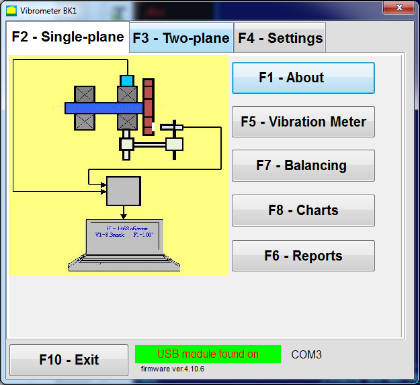
"बैलेंससेट-1ए" प्रोग्राम चलाने पर, चित्र 7.1 में दर्शाई गई प्रारंभिक विंडो दिखाई देती है।

चित्र 7.1. "बैलेंसेट-1ए" की प्रारंभिक खिड़की"
प्रारंभिक विंडो में 9 बटन हैं जिन पर क्लिक करने पर कार्यों के नाम सामने आते हैं।
F1-«हमारे बारे में»
चित्र 7.2. F1-«अबाउट» विंडो
F2-«एक समतल», F3-«दो समतल»
दबाना ""F2- एकल विमान"" (या F2 कंप्यूटर कीबोर्ड पर फ़ंक्शन कुंजी) चैनल पर माप कंपन का चयन करता है X1.
इस बटन पर क्लिक करने के बाद, चित्र 7.1 में दिखाए गए कंप्यूटर डिस्प्ले आरेख में केवल पहले मापन चैनल (या एकल तल में संतुलन प्रक्रिया) पर कंपन मापने की प्रक्रिया दर्शाई गई है।
" बटन दबाने पर"F3-दो विमान"" (या F3 कंप्यूटर कीबोर्ड पर फ़ंक्शन कुंजी दो चैनलों पर कंपन माप के मोड का चयन करती है। X1 and X2 एक साथ। (चित्र 7.3.)
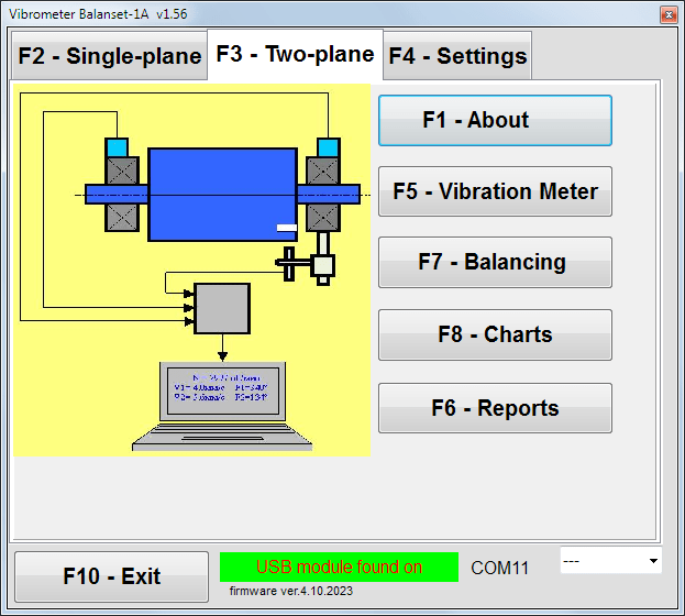
चित्र 7.3. "बैलेंससेट-1ए" की प्रारंभिक विंडो। दो तलीय संतुलन।
F4 – «सेटिंग्स»
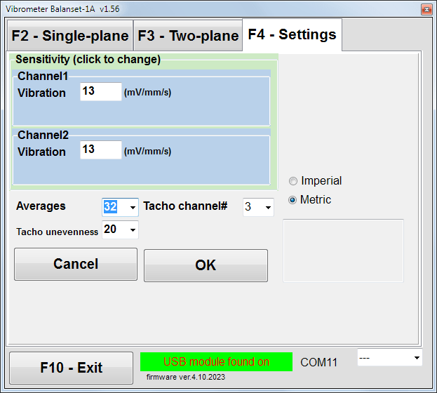
चित्र 7.4. "सेटिंग्स" विंडो
इस विंडो में आप कुछ Balanset-1A सेटिंग्स बदल सकते हैं।
- संवेदनशीलतानाममात्र मान 13 mV/mm/s है।
सेंसरों की संवेदनशीलता गुणांकों को बदलने की आवश्यकता केवल सेंसर बदलते समय ही होती है!
ध्यान दें!
जब आप संवेदनशीलता गुणांक दर्ज करते हैं, तो इसका भिन्नात्मक भाग दशमलव बिंदु (चिह्न ",") द्वारा पूर्णांक भाग से अलग किया जाता है।
- औसत निकालना - औसत निकालने की संख्या (रोटर के चक्करों की संख्या जिस पर डेटा को अधिक सटीकता के साथ औसत किया जाता है)
- टैको चैनल# - चैनल # पर टैकोमीटर कनेक्टेड है। डिफ़ॉल्ट रूप से - तीसरा चैनल।
- असमानता - आसन्न टैको पल्स के बीच की अवधि में अंतर, जो ऊपर चेतावनी देता है ""टेकोमीटर की विफलता"
- मीट्रिक/इंपीरियल - इकाइयों की प्रणाली का चयन करें।
कॉम पोर्ट नंबर स्वचालित रूप से असाइन किया जाता है।
F5 – «कंपन मीटर»
इस बटन को दबाने पर (या किसी फंक्शन की का F5 कंप्यूटर कीबोर्ड पर बटन दबाने से वर्चुअल वाइब्रेशन मीटर के एक या दो मापन चैनलों पर कंपन मापन मोड सक्रिय हो जाता है, यह बटन की स्थिति पर निर्भर करता है।"F2-एकल-विमान", ""F3-दो-विमान"।
F6 – «रिपोर्ट»
इस बटन को दबाने पर (या F6 (कंप्यूटर कीबोर्ड पर फ़ंक्शन कुंजी) संतुलन आर्काइव को चालू करता है, जिससे आप किसी विशिष्ट तंत्र (रोटर) के संतुलन के परिणामों वाली रिपोर्ट प्रिंट कर सकते हैं।
F7 – «संतुलन»
इस बटन को दबाने से (या आपके कीबोर्ड पर फ़ंक्शन कुंजी F7 को दबाने से) एक या दो सुधार तलों में संतुलन मोड सक्रिय हो जाता है, यह इस बात पर निर्भर करता है कि बटन दबाकर कौन सा माप मोड चुना गया है।"F2-एकल-विमान", ""F3-दो-विमान"।
F8 – «चार्ट»
इस बटन को दबाने पर (या F8 कंप्यूटर के कीबोर्ड पर फ़ंक्शन कुंजी दबाने से ग्राफ़िक कंपन मीटर सक्रिय हो जाता है, जिसके कार्यान्वयन से कंपन के आयाम और चरण के डिजिटल मानों के साथ-साथ इसके समय फ़ंक्शन के ग्राफ़िक्स भी डिस्प्ले पर प्रदर्शित होते हैं।
F10 – «बाहर निकलें»
इस बटन को दबाने पर (या F10 कंप्यूटर के कीबोर्ड पर फ़ंक्शन कुंजी दबाने से "बैलेंससेट-1ए" प्रोग्राम पूरा हो जाता है।
7.2. "कंपन मीटर""
"में काम करने से पहले"कंपन मीटर""मोड" में, मशीन पर कंपन सेंसर स्थापित करें और उन्हें क्रमशः यूएसबी इंटरफेस यूनिट के कनेक्टर X1 और X2 से कनेक्ट करें। टैको सेंसर को यूएसबी इंटरफेस यूनिट के इनपुट X3 से कनेक्ट किया जाना चाहिए।

चित्र 7.5 यूएसबी इंटरफ़ेस इकाई
टैको कार्य के लिए रोटर की सतह पर परावर्तक टेप लगाएं।
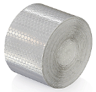
चित्र 7.6. परावर्तक टेप.
संलग्नक 1 में सेंसरों की स्थापना और विन्यास के लिए सिफारिशें दी गई हैं।
वाइब्रेशन मीटर मोड में माप शुरू करने के लिए " बटन पर क्लिक करें"F5 – कंपन मीटर"प्रोग्राम की प्रारंभिक विंडो में (चित्र 7.1 देखें)।
कंपन मीटर खिड़की दिखाई देती है (देखें। आकृति 7.7)

चित्र 7.7. कंपन मीटर मोड। तरंग और स्पेक्ट्रम।
कंपन मापन शुरू करने के लिए बटन पर क्लिक करें ""F9 – रन"(या फ़ंक्शन कुंजी दबाएँ) F9 कीबोर्ड पर
If ट्रिगर मोड ऑटो यदि जांच की जाती है - तो कंपन माप के परिणाम समय-समय पर स्क्रीन पर प्रदर्शित किए जाएंगे।
पहले और दूसरे चैनल पर कंपन के एक साथ मापन के मामले में, "शब्दों के नीचे स्थित विंडो"प्लेन 1"" और ""प्लेन 2"भरा जाएगा।
"वाइब्रेशन" मोड में कंपन मापन, फेज एंगल सेंसर को डिस्कनेक्ट करके भी किया जा सकता है। प्रोग्राम की प्रारंभिक विंडो में कुल RMS कंपन का मान (वी1, वी2) ही प्रदर्शित होगा।
कंपन मीटर मोड में अगली सेटिंग्स हैं
- RMS कम, हर्ट्ज - समग्र कंपन के RMS की गणना करने के लिए सबसे कम आवृत्ति
- बैंडविड्थ चार्ट में कंपन आवृत्ति बैंडविड्थ
- औसत - माप की सटीकता बढ़ाने के लिए औसत की संख्या
"वाइब्रेशन मीटर" मोड में काम पूरा करने के लिए बटन पर क्लिक करें।"F10 – बाहर निकलें"और प्रारंभिक विंडो पर वापस लौटें।

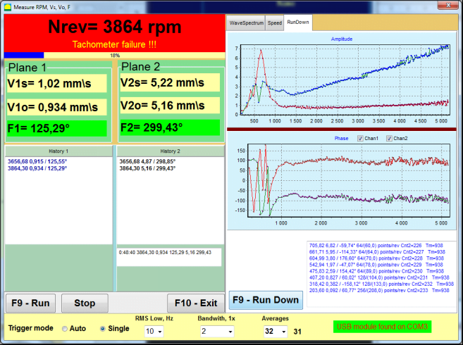
चित्र 7.8. कंपन मीटर मोड। घूर्णन गति की असमानता, 1x कंपन तरंग रूप।
चित्र 7.9. कंपन मीटर मोड। डाउनटाइम (बीटा संस्करण, कोई वारंटी नहीं!).
7.3 संतुलन प्रक्रिया
संतुलन अच्छी तकनीकी स्थिति में और सही ढंग से स्थापित यंत्रों के लिए किया जाता है। अन्यथा, संतुलन से पहले यंत्र की मरम्मत, उचित बेयरिंग्स में स्थापित और फिक्स किया जाना चाहिए। रोटर को उन अशुद्धियों से साफ किया जाना चाहिए जो संतुलन प्रक्रिया में बाधा डाल सकती हैं।
संतुलन करने से पहले वाइब्रेशन मीटर मोड (F5 बटन) में कंपन मापें, ताकि यह सुनिश्चित हो सके कि मुख्य रूप से 1x वाइब्रेशन है।
चित्र 7.10. कंपन मीटर मोड। समग्र (V1s, V2s) और 1x (V1o, V2o) कंपन की जाँच।
यदि समग्र कंपन V1s (V2s) का मान घूर्णन आवृत्ति (1x कंपन) V1o (V2o) पर कंपन के परिमाण के लगभग बराबर है, तो यह माना जा सकता है कि कंपन तंत्र में मुख्य योगदान रोटर के असंतुलन से आता है। यदि समग्र कंपन V1s (V2s) का मान 1x कंपन घटक V1o (V2o) से बहुत अधिक है, तो तंत्र की स्थिति की जाँच करने की अनुशंसा की जाती है - बेयरिंग की स्थिति, आधार पर उसका आरोहण, घूर्णन के दौरान स्थिर भागों और रोटर के बीच कोई संपर्क न हो, आदि।
आपको कंपन मीटर मोड में मापे गए मानों की स्थिरता पर भी ध्यान देना चाहिए - माप प्रक्रिया के दौरान कंपन का आयाम और चरण 10-15% से अधिक भिन्न नहीं होना चाहिए। अन्यथा, यह माना जा सकता है कि तंत्र अनुनाद के निकट क्षेत्र में कार्य कर रहा है। इस स्थिति में, रोटर की घूर्णन गति बदलें, और यदि यह संभव न हो, तो मशीन को नींव पर स्थापित करने की स्थिति बदलें (उदाहरण के लिए, इसे अस्थायी रूप से स्प्रिंग सपोर्ट पर लगाएँ)।
रोटर संतुलन के लिए प्रभाव गुणांक विधि संतुलन (3-रन विधि) का उपयोग किया जाना चाहिए।
परीक्षण रन कंपन परिवर्तन, सुधार भारों के द्रव्यमान और स्थापना स्थान (कोण) पर परीक्षण द्रव्यमान के प्रभाव को निर्धारित करने के लिए किए जाते हैं।
सबसे पहले तंत्र की मूल कम्पन निर्धारित करें (पहले बिना भार के आरंभ करें), फिर परीक्षण भार को पहले तल पर स्थापित करके दूसरी बार आरंभ करें। इसके बाद परीक्षण भार को पहले तल से हटाकर दूसरे तल पर स्थापित करें और दूसरी बार आरंभ करें।
कार्यक्रम फिर स्क्रीन पर सुधार भारों की स्थापना का वजन और स्थान (कोण) गणना करके दिखाता है।
जब एकल तल (स्थिर) में संतुलन करते समय, दूसरे स्टार्ट की आवश्यकता नहीं होती।
परीक्षण भार को रोटर पर किसी भी सुविधाजनक स्थान पर रखा जाता है, और फिर वास्तविक त्रिज्या सेटअप प्रोग्राम में दर्ज की जाती है।
(पोजीशन रेडियस का उपयोग केवल ग्राम * मिमी में असंतुलन की मात्रा की गणना के लिए किया जाता है)
महत्वपूर्ण!
- माप यंत्र की निरंतर घूर्णन गति के साथ किए जाने चाहिए!
- सुधार भारों को परीक्षण भारों के समान त्रिज्या पर स्थापित किया जाना चाहिए!
परीक्षण भार का द्रव्यमान इस प्रकार चुना जाता है कि उसके स्थापना चरण (> 20-30°) और (20-30%) के बाद कंपन का आयाम महत्वपूर्ण रूप से बदल जाए। यदि परिवर्तन बहुत कम हैं, तो बाद की गणनाओं में त्रुटि बहुत बढ़ जाती है। परीक्षण द्रव्यमान को चरण चिह्न के समान स्थान (समान कोण) पर सुविधाजनक रूप से सेट करें।
परीक्षण भार द्रव्यमान गणना सूत्र
Mt = Mr × Ksupport × Kvibration / (Rt × (N/100)²)
कहाँ:
- Mt - परीक्षण वजन द्रव्यमान, ग्राम
- Mr - रोटर का द्रव्यमान, ग्राम
- Ksupport - समर्थन कठोरता गुणांक (1-5)
- Kvibration - कंपन स्तर गुणांक (0.5-2.5)
- Rt - परीक्षण भार स्थापना त्रिज्या, सेमी
- एन - रोटर की गति, आरपीएम
समर्थन कठोरता गुणांक (Ksupport):
- 1.0 - बहुत नरम समर्थन (रबर डैम्पर्स)
- 2.0-3.0 - मध्यम कठोरता (मानक बीयरिंग)
- 4.0-5.0 - कठोर समर्थन (विशाल नींव)
कंपन स्तर गुणांक (Kvibration):
- 0.5 - कम कंपन (5 मिमी/सेकंड तक)
- 1.0 - सामान्य कंपन (5-10 मिमी/सेकंड)
- 1.5 - उच्च कंपन (10-20 मिमी/सेकंड)
- 2.0 - उच्च कंपन (20-40 मिमी/सेकंड)
- 2.5 - अत्यधिक कंपन (>40 मिमी/सेकंड)
🔗 हमारे ऑनलाइन कैलकुलेटर का उपयोग करें:
परीक्षण वजन कैलकुलेटर →⚠️ महत्वपूर्ण!
प्रत्येक परीक्षण रन के बाद परीक्षण द्रव्यमान हटा दिए जाते हैं! सुधार भार परीक्षण भार स्थापना के स्थान से गणना किए गए कोण पर सेट किए जाते हैं। रोटर के घूर्णन की दिशा में!
कोण गणना की व्याख्या:
करेक्शन वेट इंस्टॉलेशन एंगल है हमेशा परीक्षण भार स्थापना बिंदु से रोटर घूर्णन की दिशा में गणना की जाती है।
- शून्य बिंदु (0°): आपने परीक्षण भार जिस सटीक स्थान पर स्थापित किया है, वह आपका संदर्भ बिंदु (0 डिग्री) बन जाता है।
- दिशा: रोटर जिस दिशा में घूमता है, उसी दिशा में कोण मापें।
उदाहरण: यदि रोटर दक्षिणावर्त घूमता है, तो परीक्षण भार की स्थिति से दक्षिणावर्त दिशा में कोण मापें। - व्याख्या: यदि प्रोग्राम किसी कोण को प्रदर्शित करता है १२०°, आपको सुधार भार स्थापित करना होगा 120 डिग्री आगे घूर्णन की दिशा में परीक्षण भार की स्थिति से आगे।
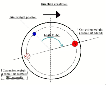
चित्र 7.11. सुधार भार आरोहण.
अनुशंसित!
गतिशील संतुलन करने से पहले, यह सुनिश्चित करना उचित है कि स्थैतिक असंतुलन बहुत अधिक न हो। क्षैतिज अक्ष वाले रोटरों के लिए, रोटर को वर्तमान स्थिति से 90 डिग्री के कोण पर मैन्युअल रूप से घुमाया जा सकता है। यदि रोटर स्थैतिक रूप से असंतुलित है, तो उसे संतुलन की स्थिति में घुमाया जाएगा। रोटर के संतुलन की स्थिति में आने के बाद, रोटर की लंबाई के लगभग मध्य भाग में शीर्ष बिंदु पर संतुलन भार स्थापित करना आवश्यक है। भार इस प्रकार चुना जाना चाहिए कि रोटर किसी भी स्थिति में गति न करे।
इस तरह के पूर्व-संतुलन से अत्यधिक असंतुलित रोटर के प्रथम प्रारंभ में कंपन की मात्रा कम हो जाएगी।
सेंसर स्थापना और माउंटिंग
वीकंपन सेंसर को मशीन पर चयनित माप बिंदु पर स्थापित किया जाना चाहिए और यूएसबी इंटरफ़ेस यूनिट के इनपुट X1 से जोड़ा जाना चाहिए।
दो माउंटिंग कॉन्फ़िगरेशन हैं:
- चुम्बक
- थ्रेडेड स्टड M4
ऑप्टिकल टैको सेंसर को USB इंटरफ़ेस यूनिट के इनपुट X3 से जोड़ा जाना चाहिए। इसके अलावा, इस सेंसर के उपयोग के लिए रोटर की सतह पर एक विशेष परावर्तक चिह्न लगाया जाना चाहिए।
📏 ऑप्टिकल सेंसर इंस्टॉलेशन संबंधी आवश्यकताएँ
- ✓रोटर सतह से दूरी: 50-500 मिमी (सेंसर मॉडल पर निर्भर करता है)
- ✓परावर्तक टेप की चौड़ाई: न्यूनतम 1-1.5 सेमी (गति और त्रिज्या पर निर्भर करता है)
- ✓अभिविन्यास: रोटर सतह के लंबवत
- ✓माउंटिंग: स्थिर स्थिति के लिए चुंबकीय स्टैंड या क्लैंप का उपयोग करें
- ✓सीधी धूप से बचें या सेंसर/टेप पर उज्ज्वल कृत्रिम प्रकाश
💡 टेप चौड़ाई गणना: इष्टतम प्रदर्शन के लिए, टेप की चौड़ाई की गणना निम्न का उपयोग करके करें:
एल ≥ (एन × आर)/30000 ≥ 1.0-1.5 सेमी
जहां: L - टेप की चौड़ाई (सेमी), N - रोटर की गति (आरपीएम), R - टेप की त्रिज्या (सेमी)
संलग्नक 1 में सेंसरों के स्थल चयन और संतुलन के दौरान उन्हें वस्तु से जोड़ने की विस्तृत आवश्यकताएँ दी गई हैं।
7.4 एकल तल संतुलन
चित्र 7.12. "एकल तल संतुलन"
संतुलन संग्रह
"कार्यक्रम पर काम शुरू करने के लिए"एकल-तल संतुलन"" मोड पर क्लिक करें ""F2-एकल-तल"" बटन दबाएं (या कंप्यूटर कीबोर्ड पर F2 कुंजी दबाएं)।
फिर " पर क्लिक करें"F7 – संतुलन"" बटन, जिसके बाद एकल-तल संतुलन आर्काइव एक विंडो प्रकट होगी, जिसमें संतुलन संबंधी डेटा सहेजा जाएगा (देखें आकृति 7.13)।

चित्र 7.13 एकल तल में संतुलन आर्काइव चुनने के लिए विंडो।
इस विंडो में, आपको रोटर के नाम का डेटा दर्ज करना होगा (रोटर का नाम), रोटर स्थापना का स्थान (स्थान), कंपन और अवशिष्ट असंतुलन के लिए सहनशीलता (सहिष्णुता), माप की तिथि। यह डेटा एक डेटाबेस में संग्रहीत किया जाता है। साथ ही, Arc### नामक एक फ़ोल्डर बनाया जाता है, जहाँ ### उस आर्काइव का नंबर है जिसमें चार्ट, रिपोर्ट फ़ाइल आदि सहेजी जाएँगी। संतुलन पूरा होने के बाद एक रिपोर्ट फ़ाइल उत्पन्न की जाएगी जिसे अंतर्निर्मित संपादक में संपादित और मुद्रित किया जा सकता है।
आवश्यक डेटा दर्ज करने के बाद, आपको " पर क्लिक करना होगा"एफ10-ओके"" बटन, जिसके बाद ""एकल-तल संतुलन""खिड़की खुल जाएगी (चित्र 7.13 देखें)"
संतुलन सेटिंग्स (1-तल)

चित्र 7.14. एकल तल। संतुलन सेटिंग्स
इस विंडो के बाईं ओर कंपन माप के डेटा और माप नियंत्रण बटन प्रदर्शित होते हैं।"रन # 0", "रन # 1", "रनट्रिम".
इस विंडो के दाईं ओर तीन टैब हैं:
- संतुलन सेटिंग्स
- चार्ट
- परिणाम
""संतुलन सेटिंग्स""टैब" का उपयोग बैलेंसिंग सेटिंग्स दर्ज करने के लिए किया जाता है:
- ""प्रभाव गुणांक"" -
- "नया रोटर"नए रोटर के संतुलन का चयन, जिसके लिए कोई संग्रहीत संतुलन गुणांक नहीं हैं और सुधार भार के द्रव्यमान और स्थापना कोण को निर्धारित करने के लिए दो परीक्षणों की आवश्यकता होती है।
- "बचाया गया गुणांक"रोटर री-बैलेंसिंग का चयन, जिसके लिए बैलेंसिंग गुणांक सहेजे गए हैं और सुधारात्मक वजन के वजन और स्थापना कोण को निर्धारित करने के लिए केवल एक ही रन की आवश्यकता होती है।
- ""परीक्षण भार द्रव्यमान"" -
- "प्रतिशत""- सुधारात्मक वजन की गणना परीक्षण वजन के प्रतिशत के रूप में की जाती है।".
- "ग्राम"परीक्षण भार का ज्ञात द्रव्यमान दर्ज किया जाता है और सुधारात्मक भार का द्रव्यमान परिकलित किया जाता है। ग्राम या में oz इम्पीरियल प्रणाली के लिए
⚠️ ध्यान दें! यदि इसका उपयोग करना आवश्यक हो तो ""बचाया गया गुणांक"प्रारंभिक संतुलन के दौरान आगे के कार्य के लिए, परीक्षण भार को ग्राम या औंस में दर्ज किया जाना चाहिए, न कि % में। तराजू डिलीवरी पैकेज में शामिल हैं।
- ""वजन लगाने की विधि""
- "नि:शुल्क स्थिति"रोटर की परिधि पर किसी भी कोणीय स्थिति में भार स्थापित किए जा सकते हैं।
- "स्थिर स्थिति"रोटर पर निश्चित कोणीय स्थितियों में भार स्थापित किया जा सकता है, उदाहरण के लिए, ब्लेड या छेदों पर (उदाहरण के लिए 12 छेद – 30 डिग्री), आदि। निश्चित स्थितियों की संख्या उपयुक्त फ़ील्ड में दर्ज की जानी चाहिए। संतुलन के बाद, प्रोग्राम स्वचालित रूप से भार को दो भागों में विभाजित करेगा और उन स्थितियों की संख्या बताएगा जिन पर प्राप्त द्रव्यमान को स्थापित करना आवश्यक है।
- "वृत्ताकार खांचा"ग्राइंडिंग व्हील को संतुलित करने के लिए उपयोग किया जाता है। इस मामले में असंतुलन को दूर करने के लिए 3 काउंटरवेट का उपयोग किया जाता है।
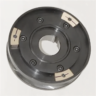
चित्र 7.17 तीन संतुलन भारों के साथ ग्राइंडिंग व्हील का संतुलन
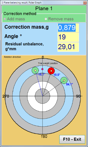
चित्र 7.18 ग्राइंडिंग व्हील का संतुलन। ध्रुवीय ग्राफ।

चित्र 7.15. परिणाम टैब। सुधार भार माउंटिंग की स्थिर स्थिति।
Z1 और Z2 - स्थापित सुधारात्मक भारों की स्थितियाँ, घूर्णन दिशा के अनुसार Z1 स्थिति से गणना की जाती हैं। Z1 वह स्थिति है जहाँ परीक्षण भार स्थापित किया गया था।
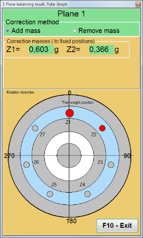
चित्र 7.16 स्थिर स्थितियाँ। ध्रुवीय आरेख।
- "मास माउंट त्रिज्या, मिमी""- "प्लेन 1" - पहले तल में परीक्षण भार की त्रिज्या। संतुलन के बाद अवशिष्ट असंतुलन के लिए सहनशीलता के अनुपालन को निर्धारित करने के लिए प्रारंभिक और अवशिष्ट असंतुलन के परिमाण की गणना करना आवश्यक है।
- "Plane1 में ट्रायल वजन छोड़ें।""आमतौर पर संतुलन प्रक्रिया के दौरान परीक्षण भार को हटा दिया जाता है। लेकिन कुछ मामलों में इसे हटाना असंभव होता है, ऐसे में गणना में परीक्षण भार के द्रव्यमान को ध्यान में रखने के लिए आपको इसमें एक चेक मार्क लगाना होगा।".
- "मैनुअल डेटा इनपुट"" - इसका उपयोग विंडो के बाईं ओर उपयुक्त फ़ील्ड में कंपन मान और चरण को मैन्युअल रूप से दर्ज करने और स्विच करते समय सुधार भार के द्रव्यमान और स्थापना कोण की गणना करने के लिए किया जाता है।"परिणाम"" टैब
- बटन ""सत्र डेटा पुनर्स्थापित करें"बैलेंसिंग के दौरान, मापा गया डेटा session1.ini फ़ाइल में सहेजा जाता है। यदि कंप्यूटर हैंग होने या अन्य कारणों से माप प्रक्रिया बाधित हो जाती है, तो इस बटन पर क्लिक करके आप माप डेटा को पुनर्स्थापित कर सकते हैं और रुकावट के क्षण से बैलेंसिंग जारी रख सकते हैं।
- मैंड्रेल अपकेंद्रीता उन्मूलन (इंडेक्स संतुलन) मैंड्रेल (बैलेंसिंग आर्बर) की उत्केंद्रता के प्रभाव को समाप्त करने के लिए अतिरिक्त प्रारंभ के साथ संतुलन करें। रोटर को इसके सापेक्ष बारी-बारी से 0° और 180° पर स्थापित करें। दोनों स्थितियों में असंतुलन मापें।
- सहिष्णुता को संतुलित करना जी x मिमी (जी-क्लास) में अवशिष्ट असंतुलन सहिष्णुताएँ दर्ज करना या गणना करना
- पोलर ग्राफ़ का उपयोग करें संतुलन परिणाम प्रदर्शित करने के लिए ध्रुवीय ग्राफ़ का उपयोग करें।
1-प्लेन संतुलन। नया रोटर।
जैसा कि ऊपर उल्लेख किया गया है, ""नया रोटर""संतुलन के लिए दो परीक्षण रन और बैलेंसिंग मशीन का कम से कम एक ट्रिम रन आवश्यक है।".
चक्र#0 (प्रारंभिक चक्र)
बैलेंसिंग रोटर पर सेंसर लगाने और सेटिंग पैरामीटर दर्ज करने के बाद, रोटर रोटेशन को चालू करना आवश्यक है और जब यह कार्यशील गति तक पहुँच जाए, तो " बटन दबाएँ।"चलाना#0"माप शुरू करने के लिए " बटन दबाएं।"चार्ट"दाएँ पैनल में एक टैब खुलेगा, जहाँ कंपन का तरंगरूप और स्पेक्ट्रम दिखाया जाएगा। टैब के निचले भाग में एक इतिहास फ़ाइल रखी जाती है, जिसमें समय संदर्भ के साथ सभी आरंभों के परिणाम सहेजे जाते हैं। डिस्क पर, यह फ़ाइल संग्रह फ़ोल्डर में memo.txt नाम से सहेजी जाती है।
ध्यान दें!
मापन शुरू करने से पहले, संतुलन मशीन के रोटर का घूर्णन चालू करना आवश्यक है (चलाना#0) और सुनिश्चित करें कि रोटर की गति स्थिर हो।
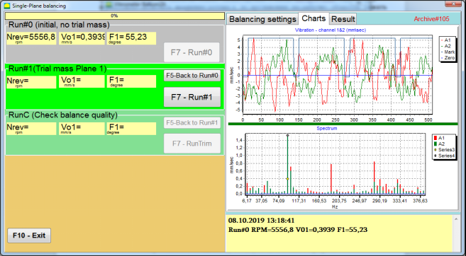
चित्र 7.19. एक प्लेन में संतुलन। प्रारंभिक चक्र (चक्र#0)। चार्ट टैब।
मापन प्रक्रिया समाप्त होने के बाद, में चलाना#0 बाएं पैनल में अनुभाग में माप के परिणाम दिखाई देते हैं - रोटर गति (आरपीएम), RMS (Vo1) और 1x कंपन का चरण (F1)।
""F5-रन#0 पर वापस"" बटन (या F5 फ़ंक्शन कुंजी) का उपयोग Run#0 अनुभाग पर वापस जाने के लिए किया जाता है और यदि आवश्यक हो, तो कंपन मापदंडों को मापने को दोहराने के लिए किया जाता है।
चरण#1 (परीक्षण द्रव्यमान विमान 1)
"खंड में कंपन मापदंडों का मापन शुरू करने से पहले"चरण#1 (परीक्षण द्रव्यमान विमान 1), परीक्षण भार को तदनुसार स्थापित किया जाना चाहिए।"परीक्षण द्रव्यमान"" मैदान।
ट्रायल वज़न स्थापित करने का उद्देश्य यह आकलन करना है कि जब एक ज्ञात वज़न को एक ज्ञात स्थान (कोण) पर स्थापित किया जाता है, तो रोटर की कंपन कैसे बदलती है। परीक्षण भार को प्रारंभिक कम्पन आयाम को या तो 30% कम या अधिक करके या प्रारंभिक चरण से 30° या उससे अधिक बदलकर कम्पन आयाम को बदलना चाहिए।
यदि इसका उपयोग करना आवश्यक हो तो ""बचाया गया गुणांक"आगे के कार्य के लिए संतुलन स्थापित करने हेतु, परीक्षण भार की स्थापना का स्थान (कोण) परावर्तक चिह्न के स्थान (कोण) के समान होना चाहिए।
संतुलन मशीन के रोटर का घूर्णन पुनः चालू करें और सुनिश्चित करें कि इसकी घूर्णन आवृत्ति स्थिर है। फिर " पर क्लिक करें।"F7-Run#1"" बटन दबाएं (या कंप्यूटर कीबोर्ड पर F7 कुंजी दबाएं)।
संबंधित विंडो में माप के बाद ""चरण#1 (परीक्षण द्रव्यमान विमान 1)"" अनुभाग, रोटर गति (आरपीएम) को मापने के परिणाम, साथ ही साथ दिखाई देने वाले 1x कंपन के RMS घटक (Vо1) और चरण (F1) का मान।
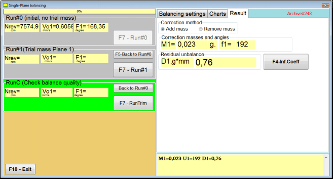
साथ ही, ""परिणाम"विंडो के दाईं ओर " टैब खुलता है।
यह टैब असंतुलन की भरपाई के लिए रोटर पर स्थापित किए जाने वाले सुधारात्मक भार के द्रव्यमान और कोण की गणना के परिणाम प्रदर्शित करता है।
इसके अलावा, ध्रुवीय निर्देशांक प्रणाली का उपयोग करने के मामले में, प्रदर्शन सुधार भार का द्रव्यमान मान (M1) और स्थापना कोण (f1) दिखाता है।
इस मामले में ""निश्चित स्थितियाँ""स्थितियों की संख्या (Zi, Zj) और परीक्षण भार विभाजित द्रव्यमान दिखाया जाएगा।".
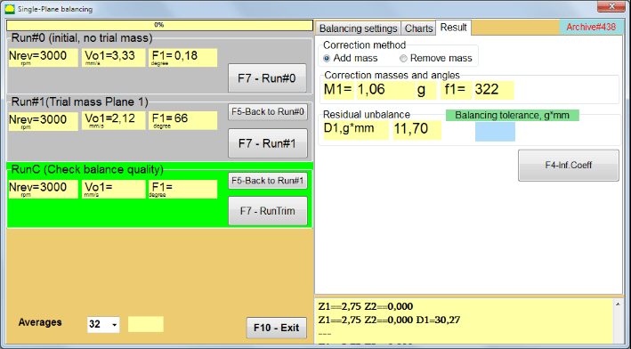
चित्र 7.20. एक समतल में संतुलन। रन#1 और संतुलन परिणाम।
If ध्रुवीय ग्राफ चेक किए जाने पर पोलर डायग्राम दिखाया जाएगा।
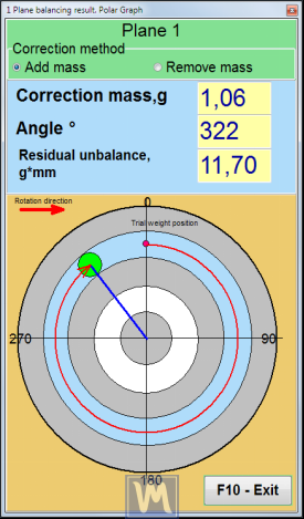
चित्र 7.21. संतुलन का परिणाम. ध्रुवीय ग्राफ.
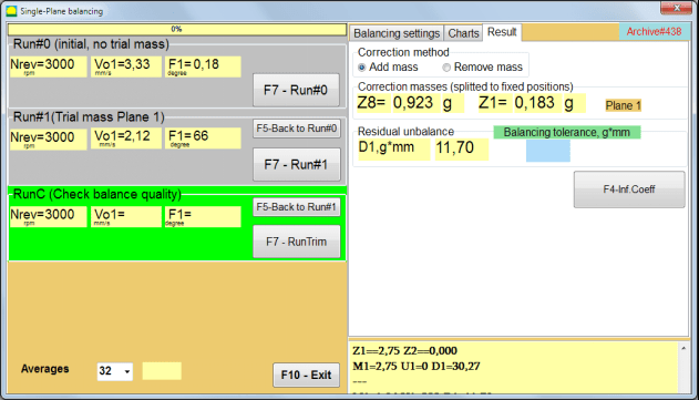
चित्र 7.22. संतुलन का परिणाम। वजन विभाजित (स्थिर स्थितियाँ)
इसके अलावा यदि ""ध्रुवीय ग्राफ""जांच की गई, ध्रुवीय ग्राफ दिखाया जाएगा।".
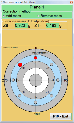
चित्र 7.23. स्थिर स्थितियों पर विभाजित भार. ध्रुवीय ग्राफ
⚠️ ध्यान दें!
- दूसरे चरण में माप प्रक्रिया पूरी करने के बाद (""चरण#1 (परीक्षण द्रव्यमान विमान 1)"संतुलन मशीन के संचालन के दौरान, घूर्णन को रोकना और स्थापित परीक्षण भार को हटाना आवश्यक है। फिर परिणाम टैब डेटा के अनुसार रोटर पर सुधारात्मक भार स्थापित करें (या हटाएँ)।
यदि परीक्षण भार नहीं हटाया गया है, तो आपको " पर स्विच करना होगा"संतुलन सेटिंग्स"टैब दबाएं और चेकबॉक्स चालू करें।"Plane1 में ट्रायल वेट छोड़ें"फिर वापस " पर स्विच करें"परिणाम"" टैब। सुधार भार का वजन और स्थापना कोण स्वचालित रूप से पुनर्गणना किए जाते हैं।
- सुधारात्मक भार की कोणीय स्थिति परीक्षण भार की स्थापना के स्थान से निर्धारित की जाती है। कोण के संदर्भ की दिशा रोटर के घूर्णन की दिशा के साथ मेल खाती है।
- इस मामले में ""स्थिर स्थिति""- 1st स्थिति (Z1) परीक्षण भार की स्थापना के स्थान के साथ मेल खाती है। स्थिति संख्या की गणना की दिशा रोटर की घूर्णन दिशा में है।
- डिफ़ॉल्ट रूप से रोटर में सुधारात्मक भार जोड़ा जाएगा। यह " में सेट किए गए लेबल द्वारा इंगित किया गया है।"Add"" फ़ील्ड। यदि वज़न हटा रहे हैं (उदाहरण के लिए, ड्रिलिंग द्वारा), तो आपको " में एक निशान लगाना होगा।"मिटायें""क्षेत्र, जिसके बाद सुधार भार की कोणीय स्थिति स्वचालित रूप से 180º से बदल जाएगी।
ऑपरेटिंग विंडो में संतुलन रोटर पर सुधार भार स्थापित करने के बाद, रनसी (ट्रिम) करना और निष्पादित संतुलन की प्रभावशीलता का मूल्यांकन करना आवश्यक है।
RunC (बैलेंस गुणवत्ता की जाँच करें)
⚠️ ध्यान दें! पर मापन शुरू करने से पहले RunC, मशीन के रोटर का घूर्णन चालू करना आवश्यक है और यह सुनिश्चित करना है कि यह संचालन मोड (स्थिर घूर्णन आवृत्ति) में प्रवेश कर गया है।
कंपन मापन करने के लिए"RunC (बैलेंस गुणवत्ता की जाँच करें)"" अनुभाग पर क्लिक करें ""F7 – रनट्रिम"" बटन दबाएं (या कीबोर्ड पर F7 कुंजी दबाएं)।
माप प्रक्रिया के सफलतापूर्वक पूरा होने पर, ""RunC (बैलेंस गुणवत्ता की जाँच करें)"बाएं पैनल में " अनुभाग में, रोटर गति (आरपीएम) को मापने के परिणाम, साथ ही 1x कंपन के RMS घटक (Vo1) और चरण (F1) का मान दिखाई देता है।
"में"परिणाम"" टैब" पर क्लिक करने पर, अतिरिक्त सुधारात्मक भार के द्रव्यमान और स्थापना कोण की गणना के परिणाम प्रदर्शित होते हैं।
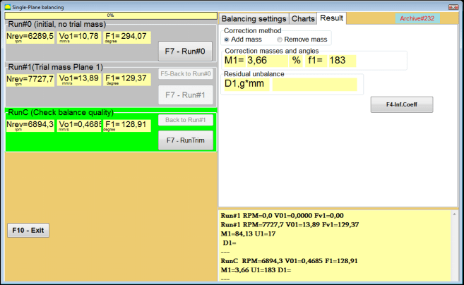
चित्र 7.24. एक समतल में संतुलन। रनट्रिम का निष्पादन। परिणाम टैब
शेष असंतुलन की भरपाई के लिए इस भार को रोटर पर पहले से स्थापित सुधार भार में जोड़ा जा सकता है। इसके अतिरिक्त, संतुलन के बाद प्राप्त शेष रोटर असंतुलन इस विंडो के निचले भाग में प्रदर्शित होता है।
जब संतुलित रोटर के अवशिष्ट कंपन और/या अवशिष्ट असंतुलन की मात्रा तकनीकी दस्तावेज़ों में निर्धारित सहनशीलता आवश्यकताओं को पूरा करती है, तब संतुलन प्रक्रिया पूरी की जा सकती है।
अन्यथा, संतुलन प्रक्रिया जारी रह सकती है। यह क्रमिक अनुमान विधि को संतुलित रोटर पर सुधारात्मक भार की स्थापना (हटाने) के दौरान होने वाली संभावित त्रुटियों को ठीक करने की अनुमति देता है।
बैलेंसिंग रोटर पर बैलेंसिंग प्रक्रिया जारी रखते समय, अतिरिक्त सुधारात्मक द्रव्यमान को स्थापित (हटाना) आवश्यक है, जिसके पैरामीटर " अनुभाग में दर्शाए गए हैं।"सुधार द्रव्यमान और कोण".
प्रभाव गुणांक (एक-तल)
""F4-प्रभाव गुणांक"" बटन में ""परिणाम"कैलिब्रेशन रन के परिणामों से गणना किए गए रोटर संतुलन गुणांक (प्रभाव गुणांक) को देखने और कंप्यूटर मेमोरी में संग्रहीत करने के लिए "टैब" का उपयोग किया जाता है।
जब इसे दबाया जाता है, तो ""प्रभाव गुणांक (एकल तल)"कंप्यूटर डिस्प्ले पर एक विंडो दिखाई देती है, जिसमें अंशांकन (परीक्षण) रन के परिणामों से गणना किए गए संतुलन गुणांक प्रदर्शित होते हैं। यदि इस मशीन के बाद के संतुलन के दौरान इसका उपयोग किया जाना है, तो..."बचाया गया गुणांक""इस मोड में, इन गुणांकों को कंप्यूटर मेमोरी में संग्रहीत किया जाना चाहिए।".
ऐसा करने के लिए, " पर क्लिक करें"F9 - सहेजें"" बटन पर क्लिक करें और दूसरे पृष्ठ पर जाएं ""प्रभाव गुणांक. पुरालेख. एकल तल."

चित्र 7.25. प्रथम तल में संतुलन गुणांक
फिर आपको इस मशीन का नाम " में दर्ज करना होगा"रोटर"" कॉलम पर क्लिक करें ""F2-सहेजें"कंप्यूटर पर निर्दिष्ट डेटा सहेजने के लिए "बटन" दबाएं।
फिर आप " बटन दबाकर पिछली विंडो पर वापस जा सकते हैं।"F10-निकास"" बटन (या कंप्यूटर कीबोर्ड पर F10 फ़ंक्शन कुंजी)।
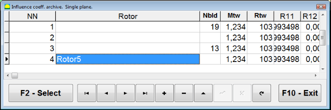
चित्र 7.26. "प्रभाव गुणांक संग्रह. एकल तल.""
संतुलन रिपोर्ट
सभी डेटा सहेजे जाने और बैलेंसिंग रिपोर्ट तैयार होने के बाद, आप बिल्ट-इन एडिटर में रिपोर्ट देख और संपादित कर सकते हैं। विंडो में ""एक ही तल में संग्रह को संतुलित करना"" (चित्र 7.9) बटन दबाएँ ""F9 - रिपोर्ट"बैलेंसिंग रिपोर्ट एडिटर तक पहुंचने के लिए।
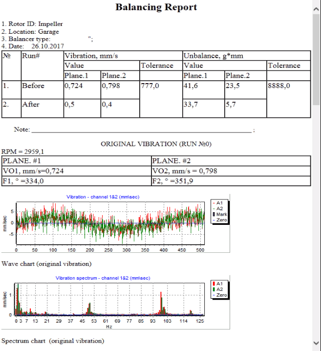
चित्र 7.27. संतुलन रिपोर्ट.
1 तल में सहेजे गए प्रभाव गुणांकों के साथ सहेजे गए गुणांक संतुलन प्रक्रिया
मापन प्रणाली की स्थापना (प्रारंभिक डेटा का इनपुट)
बचाए गए गुणांक का संतुलन एक ऐसी मशीन पर किया जा सकता है जिसके संतुलन गुणांक पहले से ही निर्धारित किए जा चुके हैं और कंप्यूटर की मेमोरी में दर्ज किए जा चुके हैं।
⚠️ ध्यान दें! सहेजे गए गुणांकों के साथ संतुलन करते समय, कंपन सेंसर और फेज एंगल सेंसर को प्रारंभिक संतुलन के दौरान की तरह ही स्थापित किया जाना चाहिए।
प्रारंभिक डेटा का इनपुट बचाए गए गुणांक का संतुलन (जैसा कि प्राथमिक के मामले में है)"नया रोटर"संतुलन की शुरुआत होती है"एकल विमान संतुलन। संतुलन सेटिंग्स।".
इस मामले में, ""प्रभाव गुणांक"" अनुभाग में, " का चयन करें"सहेजा गया गुणांक"" आइटम। इस मामले में, " का दूसरा पृष्ठ"प्रभाव गुणांक संग्रह। एकल विमान.जो सहेजे गए संतुलन गुणांकों का एक संग्रह संग्रहीत करता है।
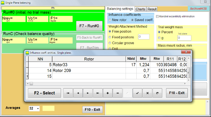
चित्र 7.28. 1 समतल में सहेजे गए प्रभाव गुणांकों के साथ संतुलन
इस संग्रह की तालिका में "►" या "◄" नियंत्रण बटनों का उपयोग करके आगे बढ़ते हुए, आप अपनी रुचि की मशीन के संतुलन गुणांकों के साथ वांछित रिकॉर्ड का चयन कर सकते हैं। फिर, वर्तमान मापों में इस डेटा का उपयोग करने के लिए, " बटन दबाएँ।"F2 – चयन करें"" बटन।
उसके बाद, " की अन्य सभी विंडो की सामग्री"एकल विमान संतुलन। संतुलन सेटिंग्स।"" स्वचालित रूप से भर दिए जाते हैं।
प्रारंभिक डेटा का इनपुट पूरा करने के बाद, आप मापना शुरू कर सकते हैं।
सहेजे गए प्रभाव गुणांकों के साथ संतुलन के दौरान माप
सहेजे गए प्रभाव गुणांकों के साथ संतुलन के लिए केवल एक प्रारंभिक चक्र और संतुलन मशीन का कम से कम एक परीक्षण चक्र आवश्यक होता है।
⚠️ ध्यान दें! मापन शुरू करने से पहले, रोटर का घूर्णन चालू करना और यह सुनिश्चित करना आवश्यक है कि घूर्णन आवृत्ति स्थिर हो।
कंपन मापदंडों के मापन को पूरा करने के लिए"चक्र#0 (प्रारंभिक, बिना परीक्षण द्रव्यमान)"" अनुभाग, दबाएँ ""F7 – चलाएँ#0"(या कंप्यूटर कीबोर्ड पर F7 कुंजी दबाएं)।
चित्र 7.29. एक समतल में सहेजे गए प्रभाव गुणांकों के साथ संतुलन। एक रन के बाद के परिणाम।
"के संबंधित क्षेत्रों में"चलाना#0"" अनुभाग में, रोटर गति (आरपीएम) को मापने के परिणाम, RMS घटक (Vо1) का मान और 1x कंपन का चरण (F1) दिखाई देता है।
साथ ही, ""परिणाम"" टैब में सुधारात्मक भार के द्रव्यमान और कोण की गणना के परिणाम प्रदर्शित होते हैं, जिसे असंतुलन की भरपाई के लिए रोटर पर स्थापित किया जाना चाहिए।
इसके अलावा, ध्रुवीय निर्देशांक प्रणाली का उपयोग करने के मामले में, प्रदर्शन द्रव्यमान मूल्यों और सुधार भार के स्थापना कोणों को दर्शाता है।
स्थिर स्थितियों पर सुधारात्मक भार के विभाजन के मामले में, संतुलन रोटर की स्थितियों की संख्या और उन पर स्थापित किए जाने वाले भार का द्रव्यमान प्रदर्शित किया जाता है।
इसके अतिरिक्त, प्राथमिक संतुलन के लिए धारा 7.4.2 में दिए गए सुझावों के अनुसार संतुलन प्रक्रिया की जाती है।
मैंड्रेल अपकेंद्रीता उन्मूलन (इंडेक्स संतुलन)
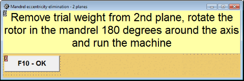
यदि संतुलन के दौरान रोटर को एक बेलनाकार मैंड्रेल में स्थापित किया जाता है, तो मैंड्रेल की अपकेंद्रीता अतिरिक्त त्रुटि उत्पन्न कर सकती है। इस त्रुटि को दूर करने के लिए रोटर को मैंड्रेल में 180° घुमाकर एक अतिरिक्त संतुलन चलाना चाहिए। इसे इंडेक्स संतुलन कहा जाता है।
इंडेक्स बैलेंसिंग करने के लिए Balanset-1A प्रोग्राम में एक विशेष विकल्प प्रदान किया गया है। जब 'मैंड्रेल अपकेंद्रियता उन्मूलन' को चेक किया जाता है, तो बैलेंसिंग विंडो में एक अतिरिक्त RunEcc अनुभाग दिखाई देता है।

चित्र 7.30. इंडेक्स संतुलन के लिए कार्य विंडो।
Run #1 (ट्रायल मास प्लेन 1) चलाने के बाद, एक विंडो दिखाई देगी।
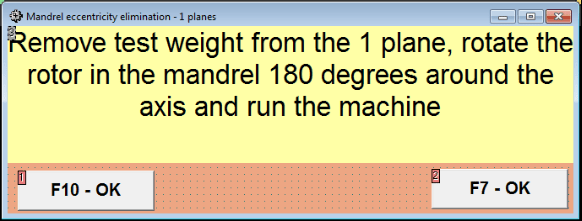
चित्र 7.31 सूचकांक संतुलन ध्यान खिड़की।
रोटर को 180° घुमाकर स्थापित करने के बाद, रन Ecc पूरा करना होगा। प्रोग्राम स्वचालित रूप से मैंड्रेल की उत्केन्द्रता को प्रभावित किए बिना वास्तविक रोटर असंतुलन की गणना करेगा।
7.5 दो तल संतुलन
में काम शुरू करने से पहले दो प्लेन संतुलन इस मोड में, चयनित माप बिंदुओं पर मशीन के शरीर पर वाइब्रेशन सेंसर स्थापित करना और उन्हें क्रमशः माप इकाई के इनपुट X1 और X2 से जोड़ना आवश्यक है।
एक ऑप्टिकल फेज एंगल सेंसर को मापिंग इकाई के इनपुट X3 से जोड़ना आवश्यक है। इसके अतिरिक्त, इस सेंसर का उपयोग करने के लिए संतुलन मशीन की सुलभ रोटर सतह पर एक परावर्तक टेप चिपकाना आवश्यक है।
संतुलन के दौरान सुविधा में सेंसरों के स्थापना स्थान के चयन और उनकी माउंटिंग के लिए विस्तृत आवश्यकताएँ परिशिष्ट 1 में दी गई हैं।
कार्यक्रम पर काम ""दो प्लेन संतुलन""मोड प्रोग्राम की मुख्य विंडो से शुरू होता है।".
पर क्लिक करें ""F3-दो प्लेन"" बटन दबाएं (या कंप्यूटर कीबोर्ड पर F3 कुंजी दबाएं)।
इसके अलावा, "एफ7 - बैलेंसिंग" बटन पर क्लिक करें, जिसके बाद कंप्यूटर डिस्प्ले पर एक वर्किंग विंडो दिखाई देगी (चित्र 7.13 देखें), दो तलों में संतुलन करते समय डेटा को सहेजने के लिए संग्रह का चयन करें।
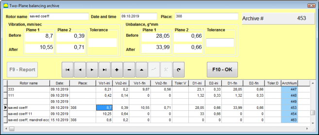
चित्र 7.32 दो-प्लेन संतुलन अभिलेखागार विंडो।
इस विंडो में आपको संतुलित रोटर का डेटा दर्ज करना होगा। " बटन दबाने के बाद"एफ10-ओके"" बटन दबाने पर एक बैलेंसिंग विंडो दिखाई देगी।
संतुलन सेटिंग्स (2-प्लेन)
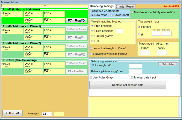
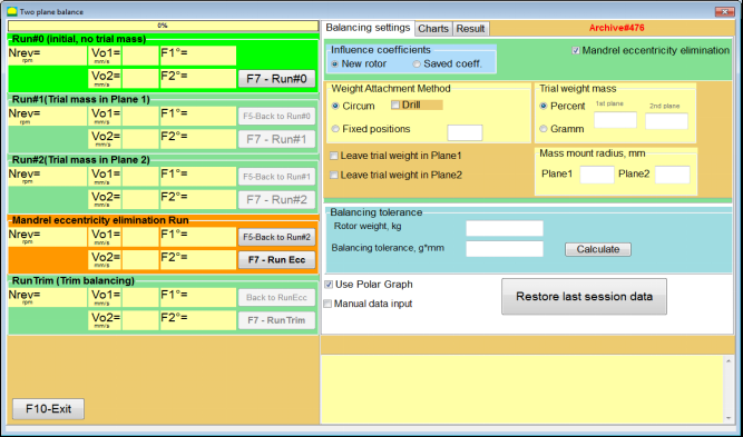
चित्र 7.33. दो समतलों में संतुलन विंडो।
खिड़की के दाहिनी ओर ""संतुलन सेटिंग्स"बैलेंसिंग से पहले सेटिंग्स दर्ज करने के लिए टैब।
- प्रभाव गुणांक - नए रोटर को संतुलित करना या संग्रहित प्रभाव गुणांकों (संतुलन गुणांकों) का उपयोग करके संतुलन स्थापित करना।
- मैंड्रेल विकेंद्रीकरण का उन्मूलन - मैंड्रेल की विलक्षणता के प्रभाव को समाप्त करने के लिए अतिरिक्त स्टार्ट के साथ संतुलन स्थापित करना
- वजन संलग्न करने की विधि - रोटर की परिधि पर किसी भी स्थान पर या किसी निश्चित स्थिति में सुधारात्मक भार स्थापित करना। भार हटाते समय ड्रिलिंग के लिए गणना करना।
- "नि:शुल्क स्थिति"रोटर की परिधि पर किसी भी कोणीय स्थिति में भार स्थापित किए जा सकते हैं।
- "स्थिर स्थिति"रोटर पर निश्चित कोणीय स्थितियों में भार स्थापित किया जा सकता है, उदाहरण के लिए, ब्लेड या छेदों पर (उदाहरण के लिए 12 छेद – 30 डिग्री), आदि। निश्चित स्थितियों की संख्या उपयुक्त फ़ील्ड में दर्ज की जानी चाहिए। संतुलन के बाद, प्रोग्राम स्वचालित रूप से भार को दो भागों में विभाजित करेगा और उन स्थितियों की संख्या बताएगा जिन पर प्राप्त द्रव्यमान को स्थापित करना आवश्यक है।
- परीक्षण द्रव्यमान - परीक्षण भार
- Plane1 / Plane2 में ट्रायल वजन छोड़ें संतुलन बनाते समय परीक्षण भार को हटा दें या वहीं छोड़ दें।
- मास माउंट त्रिज्या, मिमी - परीक्षण और सुधारात्मक भार लगाने की त्रिज्या
- सहिष्णुता को संतुलित करना ग्राम-मिमी में अवशिष्ट असंतुलन सहनशीलता दर्ज करना या उसकी गणना करना
- पोलर ग्राफ़ का उपयोग करें - संतुलन परिणामों को प्रदर्शित करने के लिए ध्रुवीय ग्राफ का उपयोग करें
- मैनुअल डेटा इनपुट - संतुलन भार की गणना के लिए मैन्युअल डेटा प्रविष्टि
- पिछले सत्र का डेटा पुनर्स्थापित करें - संतुलन प्रक्रिया जारी रखने में विफलता की स्थिति में पिछले सत्र के माप डेटा की पुनर्प्राप्ति।
2 प्लेन संतुलन। नया रोटर
मापन प्रणाली की स्थापना (प्रारंभिक डेटा का इनपुट)
के लिए प्रारंभिक डेटा का इनपुट नया रोटर संतुलन में ""दो विमानों का संतुलन. सेटिंग्स".
इस मामले में, ""प्रभाव गुणांक"" अनुभाग में, " का चयन करें"नया रोटर"" वस्तु।
इसके अलावा, अनुभाग में ""परीक्षण द्रव्यमान"आपको परीक्षण भार के द्रव्यमान की माप की इकाई का चयन करना होगा।"ग्राम"" या ""प्रतिशत".
माप की इकाई का चयन करते समय ""प्रतिशत"सुधारात्मक भार के द्रव्यमान की सभी आगे की गणनाएँ परीक्षण भार के द्रव्यमान के सापेक्ष प्रतिशत के रूप में की जाएंगी।
" का चयन करते समय"ग्राम""माप की इकाई ग्राम में है, सुधारात्मक भार के द्रव्यमान की सभी आगे की गणनाएँ ग्राम में की जाएँगी। फिर शिलालेख के दाईं ओर स्थित विंडो में दर्ज करें।""ग्राम"रोटर पर स्थापित किए जाने वाले परीक्षण भारों का द्रव्यमान।
⚠️ ध्यान दें! यदि इसका उपयोग करना आवश्यक हो तो ""बचाया गया गुणांक"प्रारंभिक संतुलन के दौरान आगे के कार्य के लिए, परीक्षण भारों का द्रव्यमान दर्ज किया जाना चाहिए। ग्राम.
फिर " का चयन करें"वजन संलग्न करने की विधि" - "परि"" या ""स्थिर स्थिति".
यदि आप " का चयन करते हैं"स्थिर स्थिति"आपको पदों की संख्या दर्ज करनी होगी।
शेष असंतुलन के लिए सहनशीलता की गणना (संतुलन सहनशीलता)
अवशिष्ट असंतुलन (संतुलन सहिष्णुता) के लिए सहनशीलता की गणना ISO 1940 कंपन में वर्णित प्रक्रिया के अनुसार की जा सकती है। स्थिर (दृढ़) अवस्था में रोटरों के लिए संतुलन गुणवत्ता आवश्यकताएँ। भाग 1. संतुलन सहिष्णुता का विनिर्देशन और सत्यापन।

चित्र 7.34. सहनशीलता गणना विंडो
प्रारंभिक रन (रन#0)
जब दो तलों में संतुलन स्थापित करते समय ""नया रोटर""मोड" में, संतुलन के लिए तीन कैलिब्रेशन रन और बैलेंसिंग मशीन का कम से कम एक टेस्ट रन आवश्यक होता है।
मशीन के पहले प्रारंभ में कंपन माप " में किया जाता है"दो समतल संतुलन""कार्यशील विंडो में""चलाना#0"" अनुभाग।
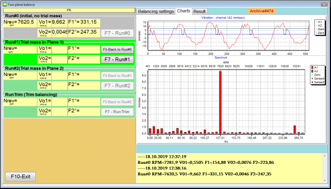
चित्र 7.35. प्रारंभिक रन के बाद दो तलों में संतुलन पर माप परिणाम।
⚠️ ध्यान दें! माप शुरू करने से पहले, संतुलन मशीन (पहले रन) के रोटर के रोटेशन को चालू करना और यह सुनिश्चित करना आवश्यक है कि यह स्थिर गति के साथ ऑपरेटिंग मोड में प्रवेश कर गया है।
में कंपन मापदंडों को मापने के लिए चलाना#0 इस सेक्शन में, " पर क्लिक करें"F7 – चलाएँ#0"" बटन दबाएं (या कंप्यूटर कीबोर्ड पर F7 कुंजी दबाएं)
रोटर गति (आरपीएम), RMS मान (वीओ1, वीओ2) और 1x कंपन के चरण (एफ1, एफ2) को मापने के परिणाम संबंधित विंडो में दिखाई देते हैं चलाना#0 अनुभाग।
रन#1। प्लेन1 में परीक्षण द्रव्यमान
कंपन मापदंडों को मापना शुरू करने से पहले ""रन#1। प्लेन1 में परीक्षण द्रव्यमान"" अनुभाग में, आपको संतुलन मशीन के रोटर का घूर्णन रोकना चाहिए और उस पर एक परीक्षण भार स्थापित करना चाहिए, जिसका द्रव्यमान " में चयनित है"परीक्षण द्रव्यमान"" अनुभाग।
⚠️ ध्यान दें!
- परीक्षण भार के द्रव्यमान को चुनने और संतुलन मशीन के रोटर पर उनके स्थापना स्थानों के प्रश्न पर परिशिष्ट 1 में विस्तार से चर्चा की गई है।
- यदि इसका उपयोग करना आवश्यक है बचाया गया गुणांक भविष्य के कार्य में, परीक्षण भार स्थापित करने का स्थान अनिवार्य रूप से उस चिह्न के स्थापित स्थान के साथ मेल खाना चाहिए, जिसका उपयोग चरण कोण को पढ़ने के लिए किया जाता है।
इसके बाद, संतुलन मशीन के रोटर का घूर्णन फिर से चालू करना आवश्यक है और यह सुनिश्चित करना है कि यह संचालन मोड में आ गया है।
कंपन मापदंडों को मापने के लिए ""रन #1। प्लेन1 में परीक्षण द्रव्यमान"" अनुभाग पर क्लिक करें ""F7 – रन#1"" बटन दबाएं (या कंप्यूटर कीबोर्ड पर F7 कुंजी दबाएं)।
मापन प्रक्रिया के सफलतापूर्वक पूरा होने पर, आपको मापन परिणामों के टैब पर वापस लाया जाता है।
इस मामले में, " की संबंधित खिड़कियों में"रन 1. प्लेन 1 में परीक्षण द्रव्यमान"इस खंड में रोटर गति (आरपीएम) को मापने के परिणाम, साथ ही RMS (Vо1, Vо2) के घटकों और 1x कंपन के चरणों (F1, F2) के मान शामिल हैं।
""प्लेन 2 में # 2.परीक्षण द्रव्यमान चलाएँ""
"खंड में कंपन मापदंडों को मापना शुरू करने से पहले"रन #2। प्लेन2 में परीक्षण द्रव्यमान"इसके लिए आपको निम्नलिखित चरणों का पालन करना होगा:
- संतुलन मशीन के रोटर के घूर्णन को रोकें;
- विमान 1 में स्थापित परीक्षण वजन को हटा दें;
- समतल 2 में एक परीक्षण भार स्थापित करें, जिसका द्रव्यमान अनुभाग " में चयनित है"परीक्षण द्रव्यमान".
इसके बाद, संतुलन मशीन के रोटर का घूर्णन चालू करें और सुनिश्चित करें कि यह परिचालन गति पर पहुँच गया है।
कंपन के मापन को शुरू करने के लिए ""रन #2। प्लेन2 में परीक्षण द्रव्यमान"" अनुभाग पर क्लिक करें ""F7 – रन # 2"" बटन (या कंप्यूटर कीबोर्ड पर F7 कुंजी दबाएं)। फिर ""परिणाम"" टैब खुलता है।
के उपयोग के मामले में वजन संलग्न करने की विधि" - "नि:शुल्क पद, प्रदर्शन सुधारात्मक भार के द्रव्यमान मान (एम 1, एम 2) और स्थापना कोण (एफ 1, एफ 2) दिखाता है।
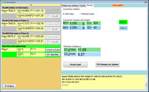
चित्र 7.36. सुधारात्मक भारों की गणना के परिणाम – मुक्त स्थिति
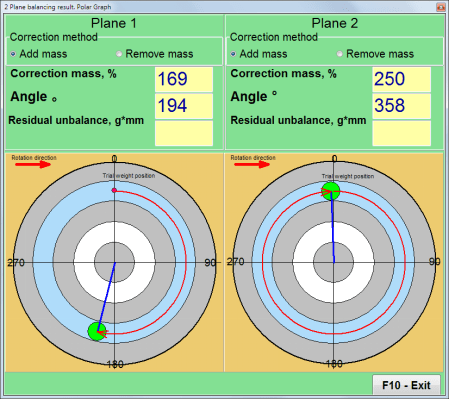
चित्र 7.37. सुधारात्मक भार की गणना के परिणाम – मुक्त स्थिति। ध्रुवीय आरेख
वजन संलग्न करने की विधि का उपयोग करने की स्थिति में" – "निश्चित स्थितियाँ

चित्र 7.38. सुधारात्मक भार की गणना के परिणाम - निश्चित स्थिति।
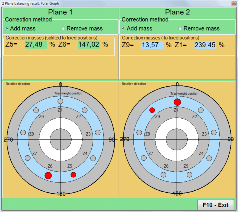
चित्र 7.39. सुधारात्मक भार की गणना के परिणाम – निश्चित स्थिति. ध्रुवीय आरेख.
वजन अटैचमेंट विधि का उपयोग करने के मामले में" – ""वृत्ताकार खांचा"
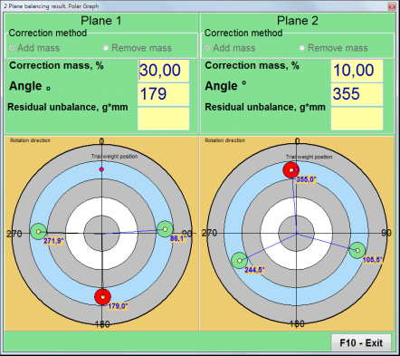
चित्र 7.40. सुधारात्मक भार की गणना के परिणाम - वृत्ताकार खांचा।
⚠️ ध्यान दें!
- माप प्रक्रिया पूरी करने के बाद बैलेंसिंग मशीन में RUN#2 पर मापन प्रक्रिया पूरी करने के बाद बैलेंसिंग मशीन में, रोटर का घूर्णन रोकें और पहले स्थापित परीक्षण भार को हटा दें। फिर आप सुधारात्मक भार स्थापित (या हटा) सकते हैं।
- ध्रुवीय निर्देशांक प्रणाली में सुधारात्मक भार की कोणीय स्थिति की गणना रोटर के घूर्णन की दिशा में परीक्षण भार की स्थापना के स्थान से की जाती है।
- इस मामले में ""स्थिर स्थिति""- 1st स्थिति (Z1) परीक्षण भार की स्थापना के स्थान के साथ मेल खाती है। स्थिति संख्या की गणना की दिशा रोटर की घूर्णन दिशा में है।
- डिफ़ॉल्ट रूप से रोटर में सुधारात्मक भार जोड़ा जाएगा। यह " में सेट किए गए लेबल द्वारा इंगित किया गया है।"Add"" फ़ील्ड। यदि वज़न हटा रहे हैं (उदाहरण के लिए, ड्रिलिंग द्वारा), तो आपको " में एक निशान लगाना होगा।"मिटायें""क्षेत्र, जिसके बाद सुधार भार की कोणीय स्थिति स्वचालित रूप से 180º से बदल जाएगी।
रन सी (ट्रिम रन)
संतुलन रोटर पर सुधार भार स्थापित करने के बाद RunC (ट्रिम) करना आवश्यक है और किए गए संतुलन की प्रभावशीलता का मूल्यांकन करना चाहिए।
⚠️ ध्यान दें! परीक्षण रन पर माप शुरू करने से पहले, मशीन के रोटर के रोटेशन को चालू करना और यह सुनिश्चित करना आवश्यक है कि यह ऑपरेटिंग गति में प्रवेश कर गया है।
रनट्रिम (संतुलन गुणवत्ता जांच) अनुभाग में कंपन मापदंडों को मापने के लिए, " पर क्लिक करें"F7 – रनट्रिम"" बटन दबाएं (या कंप्यूटर कीबोर्ड पर F7 कुंजी दबाएं)।
रोटर घूर्णन आवृत्ति (आरपीएम) के मापन के परिणाम, साथ ही 1x कंपन के RMS घटक (Vо1) और फेज (F1) का मान दिखाया जाएगा।
""परिणाम"कार्य विंडो के दाईं ओर "टैब" दिखाई देता है जिसमें माप परिणामों की तालिका होती है, जो अतिरिक्त सुधारात्मक भार के मापदंडों की गणना के परिणाम प्रदर्शित करती है।
इन भारों को शेष असंतुलन की भरपाई के लिए रोटर पर पहले से स्थापित सुधारात्मक भारों में जोड़ा जा सकता है।
इसके अतिरिक्त, संतुलन के बाद प्राप्त अवशिष्ट रोटर असंतुलन इस विंडो के निचले भाग में प्रदर्शित होता है।
उस स्थिति में जब संतुलित रोटर के अवशिष्ट कंपन और / या अवशिष्ट असंतुलन के मान तकनीकी दस्तावेज में स्थापित सहिष्णुता आवश्यकताओं को पूरा करते हैं, तो संतुलन प्रक्रिया पूरी की जा सकती है।
अन्यथा, संतुलन प्रक्रिया जारी रह सकती है। यह क्रमिक अनुमान विधि को संतुलित रोटर पर सुधारात्मक भार की स्थापना (हटाने) के दौरान होने वाली संभावित त्रुटियों को ठीक करने की अनुमति देता है।
बैलेंसिंग रोटर पर बैलेंसिंग प्रक्रिया जारी रखते समय, अतिरिक्त करेक्टिव मास को स्थापित (हटाना) आवश्यक है, जिसके पैरामीटर "परिणाम" विंडो में दर्शाए गए हैं।
"में"परिणाम""खिड़की में दो नियंत्रण बटन हैं जिनका उपयोग किया जा सकता है।""F4-प्रभाव गुणांक", "F5 – सुधार विमान बदलें".
प्रभाव गुणांक (2 तल)
""F4-प्रभाव गुणांक""बटन (या कंप्यूटर कीबोर्ड पर F4 फ़ंक्शन कुंजी) का उपयोग दो अंशांकन प्रारंभ के परिणामों से गणना किए गए रोटर संतुलन गुणांक को देखने और कंप्यूटर मेमोरी में सहेजने के लिए किया जाता है।
जब इसे दबाया जाता है, तो ""प्रभाव गुणांक (दो तल)"कंप्यूटर डिस्प्ले पर एक वर्किंग विंडो दिखाई देती है, जिसमें पहले तीन कैलिब्रेशन आरंभ के परिणामों के आधार पर गणना किए गए संतुलन गुणांक प्रदर्शित होते हैं।

चित्र 7.41. दो समतलों में संतुलन गुणांकों के साथ कार्य विंडो।
भविष्य में, इस प्रकार की मशीन का संतुलन करते समय, " का उपयोग करना आवश्यक होगा।"बचाया गया गुणांक""मोड और संतुलन गुणांक कंप्यूटर मेमोरी में संग्रहीत होते हैं।".
गुणांकों को सहेजने के लिए, " पर क्लिक करें"F9 – सहेजें"" बटन दबाएं और " पर जाएं"प्रभाव गुणांक संग्रह (2 विमान)"खिड़कियाँ (चित्र 7.42 देखें)
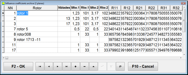
चित्र 7.42. दो समतलों में संतुलन गुणांकों के साथ कार्य विंडो का दूसरा पृष्ठ।
सुधार विमान बदलें
""F5 – सुधार विमान बदलें"" बटन का उपयोग तब किया जाता है जब सुधार तलों की स्थिति को बदलने की आवश्यकता होती है, जब द्रव्यमान और स्थापना कोणों के सुधारात्मक भार की पुनर्गणना करना आवश्यक होता है।
यह मोड मुख्य रूप से जटिल आकार के रोटरों (उदाहरण के लिए, क्रैंकशाफ्ट) के संतुलन के लिए उपयोगी है।
जब इस बटन को दबाया जाता है, तो कार्यशील विंडो ""अन्य सुधार समतलों के लिए सुधार भारों और कोणों का पुनःगणन"कंप्यूटर डिस्प्ले पर " प्रदर्शित होता है।
इस कार्य विंडो में, आपको संबंधित चित्र पर क्लिक करके चार संभावित विकल्पों में से एक का चयन करना चाहिए।
मूल सुधार समतल (Н1 और Н2) हरे रंग में चिह्नित हैं, और नए (K1 और K2), जिनके लिए यह पुनर्गणना करता है, लाल रंग में चिह्नित हैं।
फिर, ""गणना डेटा""अनुभाग" में, अनुरोधित डेटा दर्ज करें, जिसमें निम्नलिखित शामिल हैं:
- संगत सुधार विमानों (ए, बी, सी) के बीच की दूरी;
- रोटर पर सुधारात्मक भारों की स्थापना की त्रिज्याओं के नए मान (R1', R2')।
डेटा दर्ज करने के बाद, आपको " बटन दबाना होगा"F9-गणना करें"
गणना परिणाम (द्रव्यमान M1, M2 और सुधारात्मक भार f1, f2 के स्थापना कोण) इस कार्यशील विंडो के संबंधित अनुभाग में प्रदर्शित किए जाते हैं।
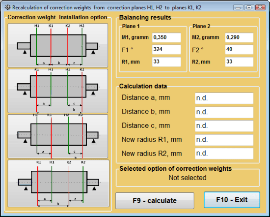
चित्र 7.43 सुधार तलों में परिवर्तन। अन्य सुधार तलों के लिए सुधार द्रव्यमान और कोण की पुनर्गणना।
2 तलों में संतुलन गुणांक बचाया गया
बचाए गए गुणांक का संतुलन यह एक ऐसी मशीन पर किया जा सकता है जिसके संतुलन गुणांक पहले से ही निर्धारित किए जा चुके हैं और कंप्यूटर की मेमोरी में सहेजे गए हैं।
⚠️ ध्यान दें! पुनः संतुलन के दौरान, कंपन सेंसर और फेज एंगल सेंसर को प्रारंभिक संतुलन के दौरान की तरह ही स्थापित किया जाना चाहिए।
पुनर्संतुलन के लिए प्रारंभिक डेटा का इनपुट " में शुरू होता है"दो समतल संतुलन. संतुलन सेटिंग्स".
इस मामले में, ""प्रभाव गुणांक"" अनुभाग में, " का चयन करें"बचाया गया गुणांक"आइटम। इस मामले में, खिड़की।"प्रभाव गुणांक संग्रह (2 विमान)""दिखाई देगा, जिसमें पहले से निर्धारित संतुलन गुणांकों का संग्रह संग्रहीत है।
इस संग्रह की तालिका में "►" या "◄" नियंत्रण बटनों का उपयोग करके आगे बढ़ते हुए, आप अपनी रुचि की मशीन के संतुलन गुणांकों के साथ वांछित रिकॉर्ड का चयन कर सकते हैं। फिर, वर्तमान मापों में इस डेटा का उपयोग करने के लिए, " बटन दबाएँ।"एफ2 – ठीक है""बटन दबाएं और पिछली कार्यशील विंडो पर वापस जाएं।
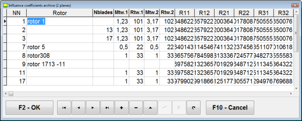
चित्र 7.44. दो समतलों में संतुलन गुणांकों के साथ कार्य विंडो का दूसरा पृष्ठ।
उसके बाद, " की अन्य सभी विंडो की सामग्री"2 pl में संतुलन। स्रोत डेटा"" यह स्वचालित रूप से भर जाता है।
बचाया गया गुणांक संतुलन
"बचाया गया गुणांक""संतुलन के लिए केवल एक ट्यूनिंग स्टार्ट और बैलेंसिंग मशीन का कम से कम एक टेस्ट स्टार्ट आवश्यक होता है।".
ट्यूनिंग की शुरुआत में कंपन मापन (रन # 0मशीन का प्रदर्शन ""दो समतलों में संतुलन""संतुलन परिणामों की तालिका के साथ कार्यशील विंडो" रन # 0 अनुभाग।
⚠️ ध्यान दें! मापन शुरू करने से पहले, संतुलन मशीन के रोटर का घूर्णन चालू करना आवश्यक है और यह सुनिश्चित करना चाहिए कि यह स्थिर गति के साथ संचालन मोड में प्रवेश कर चुका है।
में कंपन मापदंडों को मापने के लिए रन # 0 इस सेक्शन में, " पर क्लिक करें"F7 – चलाएँ#0"" बटन दबाएं (या कंप्यूटर कीबोर्ड पर F7 कुंजी दबाएं)।
रोटर गति (आरपीएम) मापने के परिणाम, साथ ही 1x कंपन के RMS (V01, V02) के घटकों और चरणों (F1, F2) के मान संबंधित फ़ील्ड्स में दिखाई देते हैं। रन # 0 अनुभाग।
साथ ही, ""परिणाम"" टैब खुलता है, जो रोटर के असंतुलन की भरपाई के लिए उस पर लगाए जाने वाले सुधारात्मक भार के मापदंडों की गणना के परिणाम प्रदर्शित करता है।
इसके अलावा, ध्रुवीय निर्देशांक प्रणाली का उपयोग करने के मामले में, प्रदर्शन सुधारात्मक भार के द्रव्यमान मूल्यों और स्थापना कोणों को दर्शाता है।
ब्लेडों पर सुधार भारों के विघटन की स्थिति में, संतुलन रोटर के ब्लेडों की संख्या और उन पर स्थापित किए जाने वाले भार का द्रव्यमान प्रदर्शित किया जाता है।
इसके अतिरिक्त, प्राथमिक संतुलन के लिए धारा 7.6.1.2 में दिए गए सुझावों के अनुसार संतुलन प्रक्रिया की जाती है।
⚠️ ध्यान दें!
- मापन प्रक्रिया पूरी होने के बाद, संतुलित मशीन को दूसरी बार शुरू करने पर उसके रोटर का घूर्णन रुकने के बाद पहले से स्थापित परीक्षण भार हटा दें। तभी आप रोटर पर सुधार भार स्थापित (या हटा) कर सकते हैं।
- रोटर से सुधार भार जोड़ने (या हटाने) के स्थान की कोणीय स्थिति की गणना ध्रुवीय निर्देशांक प्रणाली में परीक्षण भार की स्थापना स्थल पर की जाती है। गणना की दिशा रोटर के घूर्णन कोण की दिशा के अनुरूप होती है।
- ब्लेड पर संतुलन के मामले में - संतुलित रोटर ब्लेड, जिसे स्थिति 1 के रूप में निर्दिष्ट किया गया है, परीक्षण भार स्थापना के स्थान के साथ मेल खाता है। कंप्यूटर डिस्प्ले पर दिखाई गई ब्लेड की संदर्भ संख्या दिशा रोटर घूर्णन की दिशा में की जाती है।
- इस प्रोग्राम के इस संस्करण में, रोटर पर करेक्शन वेट को डिफ़ॉल्ट रूप से जोड़ा जाना तय है। "जोड़ना" फ़ील्ड में सेट किया गया टैग इसकी पुष्टि करता है। यदि किसी वेट को हटाकर (उदाहरण के लिए ड्रिलिंग द्वारा) असंतुलन को ठीक किया जाता है, तो "हटाना" फ़ील्ड में टैग सेट करना आवश्यक है, जिसके बाद करेक्शन वेट की कोणीय स्थिति स्वचालित रूप से 180º बदल जाएगी।
मैंड्रेल की विलक्षणता का उन्मूलन (सूचकांक संतुलन) - दो तल
यदि संतुलन के दौरान रोटर को एक बेलनाकार मैंड्रेल में स्थापित किया जाता है, तो मैंड्रेल की अपकेंद्रीता अतिरिक्त त्रुटि उत्पन्न कर सकती है। इस त्रुटि को दूर करने के लिए रोटर को मैंड्रेल में 180° घुमाकर एक अतिरिक्त संतुलन चलाना चाहिए। इसे इंडेक्स संतुलन कहा जाता है।
इंडेक्स बैलेंसिंग करने के लिए Balanset-1A प्रोग्राम में एक विशेष विकल्प प्रदान किया गया है। जब 'मैंड्रेल अपकेंद्रियता उन्मूलन' को चेक किया जाता है, तो बैलेंसिंग विंडो में एक अतिरिक्त RunEcc अनुभाग दिखाई देता है।
चित्र 7.45. इंडेक्स संतुलन के लिए कार्य विंडो।
Run #2 (Trial mass Plane 2) चलाने के बाद, एक विंडो दिखाई देगी।
चित्र 7.46. ध्यान खिड़कियाँ
रोटर को 180° घुमाकर स्थापित करने के बाद, रन Ecc पूरा करना होगा। प्रोग्राम स्वचालित रूप से मैंड्रेल की उत्केन्द्रता को प्रभावित किए बिना वास्तविक रोटर असंतुलन की गणना करेगा।
7.6 चार्ट मोड
"चार्ट" मोड में काम करना प्रारंभिक विंडो (चित्र 7.1 देखें) से शुरू होता है, ""F8 – चार्ट"। फिर एक विंडो खुलती है "दो चैनलों पर कंपन का मापन। चार्ट" (चित्र 7.19 देखें)।

चित्र 7.47. ऑपरेटिंग विंडो "दो चैनलों पर कंपन का मापन। चार्ट"।
इस मोड में काम करते समय कंपन चार्ट के चार संस्करण प्लॉट करना संभव है।
पहला संस्करण पहले और दूसरे मापन चैनलों पर समग्र कंपन (कंपन वेग) का समय-क्रम फ़ंक्शन प्राप्त करने की अनुमति देता है।
दूसरा संस्करण आपको कंपन (कंपन वेग) के ग्राफ़ प्राप्त करने की अनुमति देता है, जो घूर्णन आवृत्ति और इसके उच्चतर हार्मोनिक घटकों पर होता है।
ये ग्राफ़ समकालिक फ़िल्टरिंग के परिणामस्वरूप समग्र कंपन समय फलन से प्राप्त किए गए हैं।
तीसरा संस्करण हार्मोनिक विश्लेषण के परिणामों के साथ कंपन चार्ट प्रदान करता है।
चौथा संस्करण स्पेक्ट्रम विश्लेषण के परिणामों के साथ एक कंपन चार्ट प्राप्त करने की अनुमति देता है।
समग्र कंपन के चार्ट
ऑपरेटिंग विंडो में समग्र कंपन चार्ट बनाने के लिए ""दो चैनलों पर कंपन का मापन। चार्ट""ऑपरेटिंग मोड का चयन करना आवश्यक है।""समग्र कंपन"उपयुक्त बटन पर क्लिक करके। फिर "▼" बटन पर क्लिक करके "सेकंड में अवधि" बॉक्स में कंपन का माप सेट करें और ड्रॉप-डाउन सूची से माप प्रक्रिया की वांछित अवधि का चयन करें, जो 1, 5, 10, 15 या 20 सेकंड के बराबर हो सकती है;
तैयार होने पर " बटन दबाएँ (क्लिक करें)"F9"मापें" बटन दबाने पर कंपन मापन प्रक्रिया एक साथ दो चैनलों पर शुरू हो जाती है।
मापन प्रक्रिया पूरी होने के बाद ऑपरेटिंग विंडो में पहले (लाल) और दूसरे (हरे) चैनलों की समग्र कंपन के समय-विरुद्ध-कार्य के चार्ट दिखाई देते हैं (देखें आकृति 7.47)।
इन चार्टों पर समय को X-अक्ष पर और कंपन वेग (मिमी/सेकंड) के आयाम को Y-अक्ष पर दर्शाया गया है।
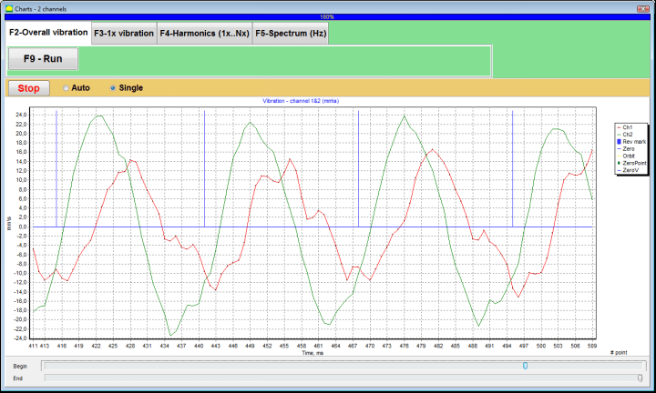
चित्र 7.48. समग्र कंपन चार्ट के समय फ़ंक्शन के आउटपुट के लिए ऑपरेटिंग विंडो
इन ग्राफ़ों में भी (नीले रंग के) निशान हैं जो समग्र कंपन के चार्ट को रोटर की घूर्णन आवृत्ति से जोड़ते हैं। इसके अतिरिक्त, प्रत्येक निशान रोटर के अगले चक्र की शुरुआत (अंत) को इंगित करता है।
X-अक्ष पर चार्ट के पैमाने को बदलने के लिए आकृति 7.20 में तीर से इंगित स्लाइडर का उपयोग किया जा सकता है।
1x कंपन के चार्ट
ऑपरेटिंग विंडो में 1x कंपन चार्ट बनाने के लिए ""दो चैनलों पर कंपन का मापन। चार्ट""ऑपरेटिंग मोड का चयन करना आवश्यक है।""1x कंपन"उपयुक्त बटन पर क्लिक करके।
फिर "1x वाइब्रेशन" ऑपरेटिंग विंडो दिखाई देती है।
" दबाएँ (क्लिक करें)"F9"मापें" बटन दबाने पर कंपन मापन प्रक्रिया एक साथ दो चैनलों पर शुरू हो जाती है।
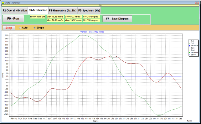
चित्र 7.49. 1x कंपन चार्ट के आउटपुट के लिए ऑपरेटिंग विंडो.
मापन प्रक्रिया के पूरा होने और परिणामों की गणितीय गणना (समग्र कंपन के समय फलन का समकालिक फ़िल्टरिंग) के बाद, मुख्य विंडो में एक अवधि के बराबर पर प्रदर्शन पर रोटर का एक चक्कर के चार्ट दिखाई देते हैं 1x कंपन दो चैनलों पर।
इस मामले में, पहले चैनल का चार्ट लाल रंग में और दूसरे चैनल का चार्ट हरे रंग में दर्शाया गया है। इन चार्टों पर रोटर की क्रांति का कोण (चिह्न से चिह्न तक) X-अक्ष पर और कंपन वेग का आयाम (मिमी/सेकंड) Y-अक्ष पर प्लॉट किया गया है।
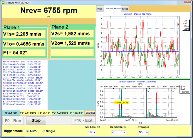
इसके अलावा, वर्किंग विंडो के ऊपरी भाग में (बटन " के दाईं ओर)"F9 – माप"") दोनों चैनलों के कंपन मापों के संख्यात्मक मान, जो हमें " में प्राप्त होते हैं"कंपन मीटर""मोड, प्रदर्शित होते हैं।
विशेष रूप से: समग्र कंपन का RMS मान (वी1, वी2), RMS का परिमाण (वी1ओ, वी2ओ) और चरण (फी, फ्जे1x कंपन और रोटर गति (Nrev) का।
हार्मोनिक विश्लेषण के परिणामों के साथ कंपन चार्ट
ऑपरेटिंग विंडो में हार्मोनिकल विश्लेषण के परिणामों के साथ एक चार्ट बनाने के लिए ""दो चैनलों पर कंपन का मापन। चार्ट""ऑपरेटिंग मोड का चयन करना आवश्यक है।""हार्मोनिक विश्लेषण"उपयुक्त बटन पर क्लिक करके।
फिर अस्थायी कार्य के चार्ट और कंपन हार्मोनिक पहलुओं के स्पेक्ट्रम के एक साथ आउटपुट के लिए एक ऑपरेटिंग विंडो दिखाई देती है, जिसकी अवधि रोटर रोटेशन आवृत्ति के बराबर या गुणक होती है।
ध्यान दें!
इस मोड में संचालन करते समय फेज एंगल सेंसर का उपयोग करना आवश्यक है, जो सेंसर से जुड़े मशीनों की रोटर आवृत्ति के साथ मापन प्रक्रिया को समकालिक करता है।
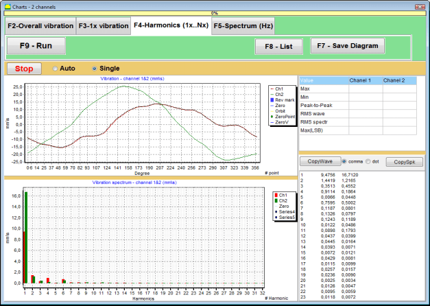
चित्र 7.50. 1x कंपन के ऑपरेटिंग विंडो हार्मोनिक्स.
तैयार होने पर " बटन दबाएँ (क्लिक करें)"F9"मापें" बटन दबाने पर कंपन मापन प्रक्रिया एक साथ दो चैनलों पर शुरू हो जाती है।
मापन प्रक्रिया पूरी होने के बाद ऑपरेटिंग विंडो में समय फ़ंक्शन (उच्च चार्ट) और 1x कंपन (निचला चार्ट) के हार्मोनिक्स के चार्ट दिखाई देते हैं।
हार्मोनिक घटकों की संख्या को X-अक्ष पर और कम्पन वेग (मिमी/सेकंड) का RMS मान को Y-अक्ष पर दर्शाया गया है।
कंपन समय डोमेन और स्पेक्ट्रम के चार्ट
स्पेक्ट्रम चार्ट बनाने के लिए " का उपयोग करें"F5-स्पेक्ट्रम"" टैब:
इसके बाद तरंग और कंपन स्पेक्ट्रम के चार्ट के एक साथ आउटपुट के लिए एक ऑपरेटिंग विंडो दिखाई देती है।

चित्र 7.51. कंपन स्पेक्ट्रम के आउटपुट के लिए ऑपरेटिंग विंडो.
तैयार होने पर " बटन दबाएँ (क्लिक करें)"F9"मापें" बटन दबाने पर कंपन मापन प्रक्रिया एक साथ दो चैनलों पर शुरू हो जाती है।
मापन प्रक्रिया पूरी होने के बाद ऑपरेटिंग विंडो में समय फ़ंक्शन (उच्च चार्ट) और कंपन स्पेक्ट्रम (निचला चार्ट) के चार्ट दिखाई देते हैं।
कंपन आवृत्ति को X-अक्ष पर और कम्पन वेग (मिमी/सेकंड) का RMS मान Y-अक्ष पर दर्शाया गया है।
इस मामले में, पहले चैनल का चार्ट लाल रंग में और दूसरे चैनल का चार्ट हरे रंग में दर्शाया गया है।
8. उपकरण के संचालन और रखरखाव पर सामान्य निर्देश
8.1 गुणवत्ता मानदंड को संतुलित करना (आईएसओ 2372 मानक)
संतुलन की गुणवत्ता का मूल्यांकन ISO 2372 मानक द्वारा निर्धारित कंपन स्तरों का उपयोग करके किया जा सकता है। नीचे दी गई तालिका विभिन्न मशीन वर्गों के लिए स्वीकार्य कंपन स्तरों को दर्शाती है:
| मशीन वर्ग | अच्छा (मिमी/सेकंड RMS) |
स्वीकार्य (मिमी/सेकंड RMS) |
अभी भी स्वीकार्य (मिमी/सेकंड RMS) |
गवारा नहीं (मिमी/सेकंड RMS) |
|---|---|---|---|---|
| वर्ग 1 कठोर नींव पर छोटी मशीनें (15 किलोवाट तक की मोटरें) |
< 0.7 | 0.7 - 1.8 | 1.8 - 4.5 | 4.5 |
| कक्षा 2 बिना नींव वाली मध्यम मशीनें (मोटर्स 15-75 किलोवाट), ड्राइव मैकेनिज्म 300 किलोवाट तक |
< 1.1 | 1.1 - 2.8 | 2.8 - 7.1 | > 7.1 |
| कक्षा 3 कठोर नींव पर बड़ी मशीनें (300 किलोवाट से अधिक उपकरण) |
1.8 से कम | 1.8 - 4.5 | 4.5 - 11 | ग्यारह |
| कक्षा 4 हल्के नींव पर बड़ी मशीनें (300 किलोवाट से अधिक उपकरण) |
2.8 से कम | 2.8 - 7.1 | 7.1 - 18 | > 18 |
नोट: ये मान संतुलन गुणवत्ता के मूल्यांकन के लिए मार्गदर्शन प्रदान करते हैं। हमेशा अपने अनुप्रयोग के लिए विशिष्ट उपकरण निर्माता विनिर्देशों और लागू मानकों का संदर्भ लें।
8.2 रखरखाव आवश्यकताएँ
🔧 नियमित रखरखाव
- ✓निर्माता विनिर्देशों के अनुसार सेंसरों का नियमित अंशांकन
- ✓सेंसरों को साफ़ रखें और चुंबकीय मलबे से मुक्त रखें
- ✓उपयोग में न होने पर उपकरण को सुरक्षात्मक केस में रखें
- ✓लेजर सेंसर को धूल और नमी से बचाएं
- ✓केबल कनेक्शनों की नियमित रूप से जांच करें कि कहीं वे घिसे या क्षतिग्रस्त तो नहीं हैं
- ✓निर्माता द्वारा अनुशंसित सॉफ़्टवेयर अपडेट करें
- ✓महत्वपूर्ण संतुलन डेटा की बैकअप प्रतियां बनाए रखें
📋 यूरोपीय संघ के रखरखाव मानक
उपकरण रखरखाव का अनुपालन निम्नलिखित होना चाहिए:
- ईएन आईएसओ 9001: गुणवत्ता प्रबंधन प्रणाली आवश्यकताएँ
- एन 13306: रखरखाव शब्दावली और परिभाषाएँ
- एन 15341: रखरखाव प्रमुख प्रदर्शन संकेतक
- यूरोपीय संघ के मशीनरी निर्देशों के अनुसार नियमित सुरक्षा निरीक्षण
अनुलग्नक 1. रोटर संतुलन
रोटर एक ऐसा पिंड है जो एक निश्चित अक्ष के चारों ओर घूमता है और इसके बेयरिंग सतहों द्वारा सपोर्ट में टिका रहता है। रोटर की बेयरिंग सतहें रोलिंग या स्लाइडिंग बेयरिंग के माध्यम से भार को सपोर्ट तक पहुंचाती हैं। "बेयरिंग सतह" शब्द का प्रयोग करते समय हमारा तात्पर्य केवल जर्नल* या जर्नल-प्रतिस्थापित सतहों से होता है।
*जर्नल (जर्मन में "जर्नल" या "पिन" के लिए ज़ैप्फेन) - शाफ्ट या अक्ष का एक हिस्सा है, जिसे होल्डर (बेयरिंग बॉक्स) द्वारा ले जाया जाता है।
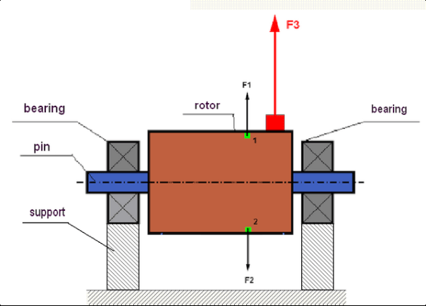
चित्र 1. रोटर और अपकेंद्री बल।
एक पूर्णतः संतुलित रोटर में, इसका द्रव्यमान घूर्णन अक्ष के सापेक्ष सममित रूप से वितरित होता है। इसका अर्थ है कि रोटर का कोई भी तत्व घूर्णन अक्ष के सापेक्ष सममित रूप से स्थित किसी अन्य तत्व के अनुरूप हो सकता है। घूर्णन के दौरान, प्रत्येक रोटर तत्व पर एक अपकेंद्री बल कार्य करता है, जो त्रिज्यात्मक दिशा (रोटर घूर्णन अक्ष के लंबवत) में निर्देशित होता है। एक संतुलित रोटर में, रोटर के किसी भी तत्व पर कार्यरत अपकेंद्री बल को सममित तत्व पर कार्यरत अपकेंद्री बल द्वारा संतुलित किया जाता है। उदाहरण के लिए, तत्व 1 और 2 (चित्र 1 में दिखाए गए और हरे रंग में रंगे हुए) पर अपकेंद्री बल F1 और F2 का प्रभाव होता है: जो मान में बराबर और दिशाओं में पूर्णतः विपरीत होते हैं। यह रोटर के सभी सममित तत्वों के लिए सत्य है और इस प्रकार रोटर पर कार्य करने वाला कुल अपकेंद्री बल 0 के बराबर होता है, रोटर संतुलित होता है। लेकिन यदि रोटर की सममिति टूट जाती है (आकृति 1 में, असममित तत्व को लाल रंग से चिह्नित किया गया है), तो असंतुलित अपकेंद्री बल F3 रोटर पर कार्य करना शुरू कर देता है।
घूर्णन करते समय, यह बल रोटर के घूर्णन के साथ-साथ दिशा भी बदलता है। इस बल से उत्पन्न गतिशील भार बियरिंग्स पर स्थानांतरित हो जाता है, जिससे उनका घिसाव तेज़ हो जाता है। इसके अतिरिक्त, इस परिवर्तनशील बल के प्रभाव में, आधारों और उस आधार का, जिस पर रोटर स्थिर है, चक्रीय विरूपण होता है, जिससे कंपन उत्पन्न होता है। रोटर के असंतुलन और उससे जुड़े कंपन को दूर करने के लिए, संतुलन द्रव्यमान स्थापित करना आवश्यक है, जो रोटर की समरूपता को बहाल करेगा।
रोटर संतुलन एक प्रक्रिया है जिसमें संतुलन द्रव्यमान जोड़कर असंतुलन को दूर किया जाता है।
संतुलन का कार्य एक या अधिक संतुलन द्रव्यमानों की स्थापना के मान और स्थान (कोण) को निर्धारित करना है।
रोटर्स के प्रकार और असंतुलन
रोटर सामग्री की मजबूती और उस पर प्रभाव डालने वाले अपकेंद्री बलों की तीव्रता को ध्यान में रखते हुए, रोटरों को दो प्रकारों में विभाजित किया जा सकता है: कठोर और लचीले।
केन्द्रापसारक बल के प्रभाव में परिचालन स्थितियों में कठोर रोटर थोड़ा विकृत हो सकते हैं, लेकिन गणना में इस विरूपण के प्रभाव को नजरअंदाज किया जा सकता है।
दूसरी ओर, लचीले रोटरों के विकृति को कभी भी अनदेखा नहीं किया जाना चाहिए। लचीले रोटरों की विकृति संतुलन समस्या के समाधान को जटिल बना देती है और कठोर रोटरों के संतुलन के कार्य की तुलना में कुछ अन्य गणितीय मॉडलों के उपयोग की आवश्यकता होती है। यह उल्लेखनीय है कि वही रोटर निम्न घूर्णन गति पर कठोर की तरह व्यवहार करता है और उच्च गति पर लचीले की तरह व्यवहार करेगा। आगे हम केवल कठोर रोटरों के संतुलन पर ही विचार करेंगे।
रोटर की लंबाई के साथ असंतुलित द्रव्यमानों के वितरण के आधार पर, दो प्रकार के असंतुलनों को पहचाना जा सकता है - स्थैतिक और गतिशील। यही बात स्थैतिक और गतिशील रोटर संतुलन पर भी लागू होती है।
रोटर के घूर्णन के बिना ही उसका स्थैतिक असंतुलन उत्पन्न होता है। दूसरे शब्दों में, जब रोटर गुरुत्वाकर्षण के प्रभाव में होता है और साथ ही "भारी बिंदु" को नीचे की ओर घुमाता है, तब यह स्थिर अवस्था में होता है। स्थैतिक असंतुलन वाले रोटर का एक उदाहरण चित्र 2 में दर्शाया गया है।

आकृति 2
गतिशील असंतुलन केवल तब होता है जब रोटर घूमता है।
चित्र 3 में गतिशील असंतुलन वाले रोटर का एक उदाहरण प्रस्तुत किया गया है।
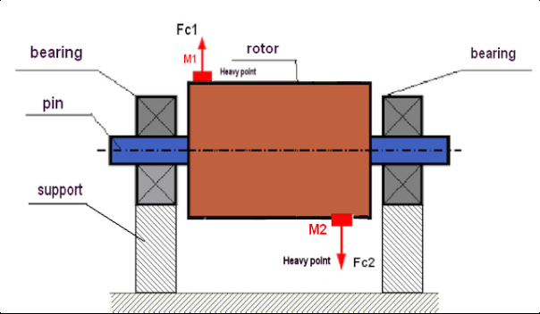
चित्र 3. रोटर का गतिज असंतुलन – अपकेंद्री बलों का युग्म
इस स्थिति में, असंतुलित समान द्रव्यमान M1 और M2 रोटर की लंबाई के अनुदिश विभिन्न सतहों पर स्थित हैं। स्थिर अवस्था में, यानी जब रोटर घूमता नहीं है, तो रोटर केवल गुरुत्वाकर्षण बल से प्रभावित होता है और इसलिए द्रव्यमान एक दूसरे को संतुलित करते हैं। गतिकी में, जब रोटर घूमने लगता है, तो द्रव्यमान M1 और M2 अपकेंद्रीय बल FЎ1 और FЎ2 से प्रभावित होने लगते हैं। ये बल मान में बराबर और दिशा में विपरीत होते हैं। हालांकि, चूंकि वे शाफ्ट की लंबाई के अनुदिश अलग-अलग स्थानों पर स्थित हैं और एक ही रेखा में नहीं हैं, इसलिए बल एक दूसरे को संतुलित नहीं करते हैं। FЎ1 और FЎ2 के बल रोटर पर एक क्षणिक बल उत्पन्न करते हैं। यही कारण है कि इस असंतुलन को "क्षणिक" भी कहा जाता है। इसके परिणामस्वरूप, असंतुलित अपकेंद्रीय बल बेयरिंग सपोर्ट पर कार्य करते हैं, जो हमारे द्वारा अनुमानित बलों से काफी अधिक हो सकते हैं और बेयरिंग के सेवा जीवन को भी कम कर सकते हैं।
क्योंकि इस प्रकार का असंतुलन केवल रोटर के घूमने के दौरान गति में ही उत्पन्न होता है, इसलिए इसे गतिशील असंतुलन कहा जाता है। इसे स्थैतिक संतुलन (या तथाकथित "चाकू पर") या किसी अन्य समान विधि से दूर नहीं किया जा सकता है। गतिशील असंतुलन को दूर करने के लिए, दो प्रतिपूरक भार स्थापित करना आवश्यक है जो M1 और M2 द्रव्यमानों से उत्पन्न होने वाले आघूर्ण के बराबर मान और विपरीत दिशा में आघूर्ण उत्पन्न करें। प्रतिपूरक भारों को M1 और M2 द्रव्यमानों के ठीक विपरीत स्थापित करना और उनके बराबर मान का होना आवश्यक नहीं है। सबसे महत्वपूर्ण बात यह है कि वे असंतुलन के ठीक क्षण में एक ऐसा आघूर्ण उत्पन्न करें जो पूरी तरह से क्षतिपूर्ति करे।
सामान्यतः, द्रव्यमान M1 और M2 एक दूसरे के बराबर नहीं होते, इसलिए स्थैतिक और गतिशील असंतुलन का संयोजन होगा। सैद्धांतिक रूप से यह सिद्ध हो चुका है कि एक कठोर रोटर के असंतुलन को दूर करने के लिए, रोटर की लंबाई के अनुदिश दो भार लगाना आवश्यक और पर्याप्त है। ये भार गतिशील असंतुलन से उत्पन्न क्षण और रोटर अक्ष के सापेक्ष द्रव्यमान की विषमता (स्थैतिक असंतुलन) से उत्पन्न अपकेंद्रीय बल दोनों को संतुलित करेंगे। सामान्यतः, गतिशील असंतुलन लंबे रोटरों, जैसे शाफ्ट, के लिए विशिष्ट होता है, और स्थैतिक असंतुलन संकरे रोटरों के लिए। हालांकि, यदि संकरा रोटर अक्ष के सापेक्ष तिरछा लगाया गया हो, या इससे भी बदतर, विकृत (तथाकथित "पहिया डगमगाहट") हो, तो इस स्थिति में गतिशील असंतुलन को दूर करना कठिन होगा (चित्र 4 देखें), क्योंकि सही संतुलनकारी क्षण उत्पन्न करने वाले भारों को लगाना मुश्किल होता है।
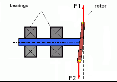
चित्र 4: डगमगाते पहिये का गतिशील संतुलन
चूंकि रोटर का संकरा किनारा एक छोटा मोमेंट उत्पन्न करता है, इसलिए इसमें अधिक द्रव्यमान वाले भारों को समायोजित करने की आवश्यकता हो सकती है। लेकिन साथ ही, समायोजित करने वाले भारों से उत्पन्न अपकेंद्रीय बलों के प्रभाव से संकरे रोटर के विरूपण के कारण एक अतिरिक्त तथाकथित "प्रेरित असंतुलन" भी उत्पन्न होता है।
उदाहरण देखें:
""रिजिड रोटर्स के संतुलन पर व्यवस्थित निर्देश"" ISO 1940-1:2003 यांत्रिक कम्पन – स्थिर (कठोर) अवस्था में रोटरों के लिए संतुलन गुणवत्ता आवश्यकताएँ – भाग 1: संतुलन सहनशीलताओं का विनिर्देशन और सत्यापन
यह संकीर्ण पंखे के पहियों के लिए स्पष्ट रूप से देखा जा सकता है, जो शक्ति असंतुलन के अलावा, एक वायुगतिकीय असंतुलन को भी प्रभावित करते हैं। और यह ध्यान रखना महत्वपूर्ण है कि वायुगतिकीय असंतुलन, वास्तव में वायुगतिकीय बल, रोटर की कोणीय गति के सीधे आनुपातिक होता है, और इसे संतुलित करने के लिए, सुधारात्मक द्रव्यमान का अपकेंद्री बल उपयोग किया जाता है, जो कोणीय गति के वर्ग के आनुपातिक होता है। इसलिए, संतुलन प्रभाव केवल एक विशिष्ट संतुलन आवृत्ति पर ही हो सकता है। अन्य गति पर एक अतिरिक्त अंतराल होगा। एक विद्युत चुम्बकीय मोटर में विद्युत चुम्बकीय बलों के बारे में भी यही कहा जा सकता है, जो कोणीय वेग के समानुपाती होते हैं। दूसरे शब्दों में, किसी भी संतुलन के साधन द्वारा तंत्र के कंपन के सभी कारणों को खत्म करना असंभव है।
कंपन के मूल सिद्धांत
कंपन चक्रीय उत्तेजना बल के प्रभाव के प्रति तंत्र डिज़ाइन की प्रतिक्रिया है। इस बल की प्रकृति भिन्न हो सकती है।
- रोटर के असंतुलन के कारण उत्पन्न अपकेंद्रीय बल एक असंतुलित बल है जो "भारी बिंदु" को प्रभावित करता है। विशेष रूप से यह बल और इसके कारण होने वाला कंपन रोटर संतुलन द्वारा समाप्त कर दिया जाता है।
- परस्पर क्रिया करने वाले बल, जिनका स्वरूप "ज्यामितीय" होता है और जो आपस में जुड़ने वाले पुर्जों के निर्माण और स्थापना में त्रुटियों के कारण उत्पन्न होते हैं। ये बल, उदाहरण के लिए, शाफ्ट जर्नल की गोलाई न होने, गियर में दांतों के प्रोफाइल में त्रुटियों, बेयरिंग रेसवे की लहरदारता, आपस में जुड़ने वाले शाफ्टों के गलत संरेखण आदि के कारण हो सकते हैं। गर्दन की गोलाई न होने की स्थिति में, शाफ्ट की धुरी शाफ्ट के घूर्णन कोण के आधार पर स्थानांतरित हो जाएगी। यद्यपि यह कंपन रोटर की गति पर प्रकट होता है, लेकिन संतुलन द्वारा इसे समाप्त करना लगभग असंभव है।
- इम्पेलर पंखों और अन्य ब्लेड तंत्रों के घूर्णन से उत्पन्न वायुगतिकीय बल। हाइड्रोलिक पंप इम्पेलरों, टर्बाइनों आदि के घूर्णन से उत्पन्न जलगतिकीय बल।
- विद्युत मशीनों के संचालन के परिणामस्वरूप उत्पन्न होने वाले विद्युत चुम्बकीय बल, उदाहरण के लिए, रोटर वाइंडिंग की विषमता, शॉर्ट-सर्किटेड घुमावों की उपस्थिति आदि के कारण।
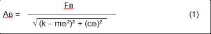
कंपन की तीव्रता (उदाहरण के लिए, इसका आयाम AB) न केवल परिपत्र आवृत्ति ω पर तंत्र पर क्रियाशील उत्तेजना बल Fт की तीव्रता पर निर्भर करती है, बल्कि तंत्र की संरचना की कठोरता k, उसका द्रव्यमान m, और डैम्पिंग गुणांक C पर भी निर्भर करती है।
विभिन्न प्रकार के सेंसरों का उपयोग कंपन और संतुलन तंत्र को मापने के लिए किया जा सकता है, जिनमें शामिल हैं:
- वाइब्रेशन त्वरण (एक्सेलेरोमीटर) मापने के लिए डिज़ाइन किए गए पूर्ण कंपन सेंसर और कंपन वेग सेंसर;
- सापेक्ष कंपन सेंसर भंवर-वर्तमान या कैपेसिटिव, कंपन को मापने के लिए डिज़ाइन किए गए हैं।
कुछ मामलों में (जब तंत्र की संरचना इसकी अनुमति देती है) बल सेंसरों का उपयोग इसके कंपन भार की जांच के लिए भी किया जा सकता है।
विशेष रूप से, इनका उपयोग हार्डबेयरिंग संतुलन मशीनों के समर्थन के कंपन भार को मापने के लिए व्यापक रूप से किया जाता है।
इसलिए कंपन बाहरी बलों के प्रभाव पर तंत्र की प्रतिक्रिया है। कंपन की मात्रा न केवल तंत्र पर कार्यरत बल की परिमाण पर निर्भर करती है, बल्कि तंत्र की कठोरता पर भी निर्भर करती है। समान परिमाण के दो बल भिन्न-भिन्न कंपन उत्पन्न कर सकते हैं। कठोर आधार संरचना वाले तंत्रों में, थोड़े से कंपन से भी गतिशील भारों द्वारा बेयरिंग इकाइयों पर महत्वपूर्ण प्रभाव पड़ सकता है। इसलिए, जब कठोर पैरों वाले यंत्रों का संतुलन किया जाता है, तो बल सेंसर और कंपन (वाइब्रो एक्सेलेरोमीटर) का उपयोग किया जाता है। कंपन सेंसर का उपयोग केवल अपेक्षाकृत लचीले समर्थन वाले यंत्रों पर किया जाता है, ठीक उसी समय जब असंतुलित अपकेंद्री बलों की क्रिया समर्थन में ध्यान देने योग्य विकृति और कंपन का कारण बनती है। बल सेंसर का उपयोग कठोर समर्थन में तब भी किया जाता है जब असंतुलन से उत्पन्न होने वाले महत्वपूर्ण बल महत्वपूर्ण कंपन का कारण नहीं बनते हैं।
संरचना की प्रतिध्वनि
हमने पहले उल्लेख किया है कि रोटर कठोर और लचीले में विभाजित होते हैं। रोटर की कठोरता या लचीलेपन को उस आधार (फाउंडेशन) की कठोरता या गतिशीलता से भ्रमित नहीं करना चाहिए जिस पर रोटर स्थित होता है। जब केंद्रापसारक बलों के प्रभाव में रोटर का विकृति (मुड़ना) नगण्य हो, तो रोटर को कठोर माना जाता है। लचीले रोटर का विकृति अपेक्षाकृत अधिक होता है: इसे नगण्य नहीं माना जा सकता।
इस लेख में हम केवल दृढ़ रोटरों के संतुलन का अध्ययन करेंगे। दृढ़ (अविकृत) रोटर, बदले में, दृढ़ या गतिशील (नमनीय) आधारों पर स्थित हो सकता है। यह स्पष्ट है कि आधारों की यह कठोरता/गतिशीलता रोटर की घूर्णन गति और परिणामी अपकेन्द्रीय बलों के परिमाण पर निर्भर करती है। पारंपरिक सीमा रोटर आधारों/आधार के मुक्त दोलनों की आवृत्ति है। यांत्रिक प्रणालियों के लिए, मुक्त दोलनों का आकार और आवृत्ति यांत्रिक प्रणाली के तत्वों के द्रव्यमान और प्रत्यास्थता द्वारा निर्धारित होती है। अर्थात्, प्राकृतिक दोलनों की आवृत्ति यांत्रिक प्रणाली की एक आंतरिक विशेषता है और बाह्य बलों पर निर्भर नहीं करती है। संतुलन अवस्था से विक्षेपित होने पर, आधार प्रत्यास्थता के कारण अपनी संतुलन स्थिति में वापस आ जाते हैं। लेकिन विशाल रोटर के जड़त्व के कारण, यह प्रक्रिया अवमंदित दोलनों की प्रकृति की होती है। ये दोलन रोटर-आधार प्रणाली के अपने दोलन होते हैं। उनकी आवृत्ति रोटर द्रव्यमान और समर्थन की लोच के अनुपात पर निर्भर करती है।
जब रोटर घूमना शुरू करता है और उसकी घूर्णन आवृत्ति उसकी अपनी दोलनों की आवृत्ति के समीप पहुँच जाती है, तो कंपन का आयाम तीव्रता से बढ़ जाता है, जो संरचना के विनाश तक भी ले जा सकता है।
यांत्रिक अनुनाद की एक घटना होती है। अनुनाद क्षेत्र में, घूर्णन गति में 100 आरपीएम की वृद्धि से कंपन दस गुना बढ़ सकता है। इस स्थिति में (अनुनाद क्षेत्र में) कंपन का चरण 180° बदल जाता है।
यदि किसी यंत्र का डिज़ाइन दोषपूर्ण है और रोटर की परिचालन गति दोलनों की प्राकृतिक आवृत्ति के निकट है, तो असहनीय रूप से उच्च कंपन के कारण यंत्र का संचालन असंभव हो जाता है। मानक संतुलन विधियाँ भी अव्यवहार्य हो जाती हैं, क्योंकि घूर्णन गति में मामूली परिवर्तन से भी मापदंडों में भारी बदलाव आ जाता है। अनुनाद संतुलन के क्षेत्र में विशेष विधियों का उपयोग किया जाता है, लेकिन इस लेख में उनका विस्तृत वर्णन नहीं किया गया है। रोटर के बंद होने पर (रन-आउट के दौरान) या झटके के प्रभाव से यंत्र के प्राकृतिक दोलनों की आवृत्ति का निर्धारण किया जा सकता है, जिसके बाद झटके के प्रति तंत्र की प्रतिक्रिया का स्पेक्ट्रल विश्लेषण किया जाता है। "बैलेंसेट-1" इन विधियों द्वारा यांत्रिक संरचनाओं की प्राकृतिक आवृत्तियों का निर्धारण करने की क्षमता प्रदान करता है।
जिन तंत्रों की संचालन गति अनुनाद आवृत्ति से अधिक होती है, अर्थात् अनुनादी मोड में संचालित होने वाले तंत्रों में, समर्थन को गतिशील माना जाता है और मुख्यतः संरचनात्मक तत्वों के त्वरण को मापने वाले कंपन त्वरणमापक का उपयोग किया जाता है। कठोर बेयरिंग मोड में संचालित तंत्रों में समर्थन को कठोर माना जाता है। इस स्थिति में बल संवेदकों का उपयोग किया जाता है।
यांत्रिक प्रणाली के रैखिक और अरैखिक मॉडल
कठोर रोटरों का संतुलन करते समय गणनाओं के लिए गणितीय मॉडल (रेखीय) का उपयोग किया जाता है। मॉडल की रेखीयता का अर्थ है कि एक मॉडल दूसरे पर प्रत्यक्ष रूप से (रेखीय रूप से) निर्भर होता है। उदाहरण के लिए, यदि रोटर पर असंतुलित द्रव्यमान दोगुना हो जाता है, तो कंपन मान भी उसी अनुपात में दोगुना हो जाएगा। कठोर रोटरों के लिए आप रेखीय मॉडल का उपयोग कर सकते हैं क्योंकि ऐसे रोटर विकृत नहीं होते हैं। लचीले रोटरों के लिए रैखिक मॉडल का उपयोग करना अब संभव नहीं है। एक लचीले रोटर के लिए, घूर्णन के दौरान भारी बिंदु के द्रव्यमान में वृद्धि के साथ, एक अतिरिक्त विकृति उत्पन्न होगी, और द्रव्यमान के अलावा, भारी बिंदु की त्रिज्या भी बढ़ जाएगी। इसलिए, एक लचीले रोटर के लिए, कंपन दोगुने से भी अधिक हो जाएगा, और सामान्य गणना विधियाँ काम नहीं करेंगी। इसके अलावा, मॉडल की रैखिकता का उल्लंघन समर्थन की लोच में परिवर्तन का कारण बन सकता है, उदाहरण के लिए, जब समर्थन की छोटी विकृतियाँ कुछ संरचनात्मक तत्वों को काम में लगाती हैं, और बड़ी विकृतियों में काम में अन्य संरचनात्मक तत्व शामिल होते हैं। इसलिए उन तंत्रों को संतुलित करना असंभव है जो आधार पर स्थिर नहीं हैं, और, उदाहरण के लिए, जो केवल फर्श पर रखे गए हैं। महत्वपूर्ण कंपन के साथ, असंतुलन बल तंत्र को फर्श से अलग कर सकता है, जिससे सिस्टम की कठोरता विशेषताओं में काफी बदलाव आता है। इंजन के पैरों को मजबूती से कसकर लगाया जाना चाहिए, बोल्ट वाले फास्टनर को कसा जाना चाहिए, वाशरों की मोटाई पर्याप्त कठोरता प्रदान करनी चाहिए, आदि। टूटे हुए बेयरिंग्स के साथ, शाफ्ट और उसके प्रभावों का एक महत्वपूर्ण विस्थापन संभव है, जो रैखिकता के उल्लंघन और उच्च-गुणवत्ता वाले संतुलन को करने में असमर्थता का भी कारण बनेगा।
संतुलन के लिए विधियाँ और उपकरण
जैसा कि ऊपर उल्लेख किया गया है, संतुलन मुख्य केंद्रीय जड़त्व अक्ष को रोटर के घूर्णन अक्ष के साथ संयोजित करने की प्रक्रिया है।
निर्दिष्ट प्रक्रिया को दो तरीकों से निष्पादित किया जा सकता है।
पहला तरीका रोटर एक्सलों की प्रक्रिया से संबंधित है, जिसे इस प्रकार किया जाता है कि एक्सलों के खंड के केंद्रों से होकर गुजरने वाला अक्ष रोटर के मुख्य केंद्रीय जड़त्व अक्ष के साथ संरेखित हो। यह तकनीक व्यवहार में शायद ही कभी उपयोग की जाती है और इस लेख में इसकी विस्तार से चर्चा नहीं की जाएगी।
दूसरा (सबसे आम) तरीका रोटर पर सुधारात्मक द्रव्यमानों को स्थानांतरित करने, स्थापित करने या हटाने से संबंधित है, जिन्हें इस प्रकार रखा जाता है कि रोटर का जड़त्व अक्ष उसके घूर्णन अक्ष के जितना संभव हो उतना निकट हो।
संतुलन के दौरान सुधारात्मक द्रव्यमानों को स्थानांतरित करना, जोड़ना या हटाना विभिन्न तकनीकी प्रक्रियाओं का उपयोग करके किया जा सकता है, जिनमें शामिल हैं: ड्रिलिंग, मिलिंग, सर्फेसिंग, वेल्डिंग, स्क्रू करना या अनस्क्रू करना, लेजर बीम या इलेक्ट्रॉन बीम से जलाना, इलेक्ट्रोलाइसिस, विद्युत-चुंबकीय वेल्डिंग आदि।
संतुलन प्रक्रिया दो तरीकों से की जा सकती है:
- संतुलित रोटर्स असेंबली (अपने स्वयं के बीयरिंग में);
- संतुलन मशीनों पर रोटर्स का संतुलन।
रोटरों को उनके स्वयं के बेयरिंग्स में संतुलित करने के लिए हम आमतौर पर विशेष संतुलन उपकरण (किट्स) का उपयोग करते हैं, जो हमें संतुलित रोटर की कंपन को उसकी घूर्णन गति पर वेक्टर रूप में मापने की अनुमति देता है, अर्थात् कंपन के आयाम और चरण दोनों को मापने के लिए।
वर्तमान में, ये उपकरण माइक्रोप्रोसेसर तकनीक के आधार पर निर्मित किए जाते हैं और (कंपन के मापन और विश्लेषण के अतिरिक्त) रोटर के असंतुलन की भरपाई के लिए उसमें स्थापित किए जाने वाले सुधारात्मक भारों के मापदंडों की स्वचालित गणना प्रदान करते हैं।
इन उपकरणों में शामिल हैं:
- कंप्यूटर या औद्योगिक नियंत्रक के आधार पर बनाई गई माप और कंप्यूटिंग इकाई;
- दो (या अधिक) कंपन सेंसर;
- चरण कोण सेंसर;
- सुविधा पर सेंसर की स्थापना के लिए उपकरण;
- एक, दो या अधिक सुधार विमानों में रोटर असंतुलन मापदंडों के माप का एक पूर्ण चक्र निष्पादित करने के लिए डिज़ाइन किया गया विशेष सॉफ्टवेयर।
बैलेंसिंग मशीनों पर रोटरों को संतुलित करने के लिए, एक विशेष बैलेंसिंग उपकरण (मशीन की मापन प्रणाली) के अलावा, एक "अनवाइंडिंग मैकेनिज्म" की आवश्यकता होती है, जिसे रोटर को सपोर्ट पर स्थापित करने और एक निश्चित गति पर इसके घूर्णन को सुनिश्चित करने के लिए डिज़ाइन किया गया हो।
वर्तमान में, सबसे आम संतुलन मशीनें दो प्रकार की होती हैं:
- अति-अनुनाद (कोमल समर्थन के साथ);
- कठोर असर (कठोर समर्थन के साथ)।
अति-प्रतिध्वनित मशीनों में अपेक्षाकृत लचीले समर्थन होते हैं, जो उदाहरण के लिए फ्लैट स्प्रिंग्स के आधार पर बनाए जाते हैं।
इन सहाराओं की प्राकृतिक दोलन आवृत्ति आमतौर पर उन पर स्थापित संतुलित रोटर की गति से 2-3 गुना कम होती है।
वाइब्रेशन सेंसर (एक्सेलेरोमीटर, वाइब्रेशन वेग सेंसर आदि) आमतौर पर एक अनुनादी मशीन के समर्थन तत्वों की कंपन को मापने के लिए उपयोग किए जाते हैं।
हार्डबेयरिंग वाली संतुलन मशीनों में अपेक्षाकृत कठोर समर्थन का उपयोग किया जाता है, जिनकी प्राकृतिक दोलन आवृत्तियाँ संतुलित रोटर की गति से 2-3 गुना अधिक होनी चाहिए।
फोर्स सेंसर आमतौर पर मशीन के समर्थन पर पड़ने वाले कंपन भार को मापने के लिए उपयोग किए जाते हैं।
हार्ड बेयरिंग बैलेंसिंग मशीनों का लाभ यह है कि इन्हें अपेक्षाकृत कम रोटर गति (400–500 आरपीएम तक) पर संतुलित किया जा सकता है, जिससे मशीन और उसकी नींव का डिज़ाइन बहुत सरल हो जाता है, साथ ही संतुलन की उत्पादकता और सुरक्षा भी बढ़ जाती है।
संतुलन तकनीक
⚠️ संतुलन प्रक्रिया केवल घूर्णन अक्ष के सापेक्ष रोटर द्रव्यमान वितरण की विषमता के कारण उत्पन्न कंपन को ही समाप्त करती है। संतुलन प्रक्रिया से अन्य प्रकार के कंपन समाप्त नहीं किए जा सकते!
संतुलन तकनीकी रूप से सेवा योग्य तंत्रों का विषय है, जिनके डिज़ाइन से परिचालन गति पर अनुनाद की अनुपस्थिति सुनिश्चित होती है, जो नींव पर सुरक्षित रूप से स्थापित और सेवा योग्य बेयरिंग्स में लगे होते हैं।
🚫 दोषपूर्ण तंत्र की मरम्मत की जानी चाहिए, और उसके बाद ही उसका संतुलन किया जाना चाहिए। अन्यथा, गुणात्मक संतुलन असंभव है।
संतुलन मरम्मत का विकल्प नहीं हो सकता!
संतुलन का मुख्य कार्य वह द्रव्यमान और स्थापना का स्थान (कोण) ज्ञात करना है, जहाँ प्रतिसंतक भारों को स्थापित किया जाता है, जिन्हें अपकेंद्री बलों द्वारा संतुलित किया जाता है।
जैसा कि ऊपर उल्लेख किया गया है, कठोर रोटरों के लिए सामान्यतः दो क्षतिपूर्ति भार स्थापित करना आवश्यक और पर्याप्त होता है। इससे स्थिर और गतिशील दोनों प्रकार का रोटर असंतुलन समाप्त हो जाएगा। संतुलन के दौरान कंपन मापन की एक सामान्य योजना निम्नलिखित प्रकार की होती है:
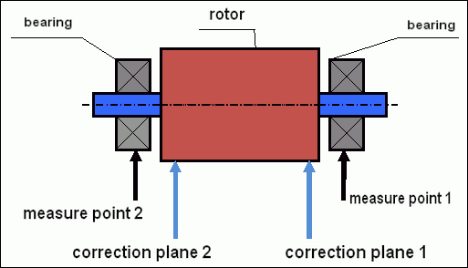
चित्र 5 गतिशील संतुलन – सुधार तल और मापन बिंदु
कंपन सेंसर बिंदु 1 और 2 पर बेयरिंग सपोर्ट्स पर स्थापित किए गए हैं। रोटर पर सीधे स्पीड मार्क लगाया जाता है, आमतौर पर उस पर परावर्तक टेप चिपकाया जाता है। यह स्पीड मार्क लेजर टैकोमीटर द्वारा रोटर की गति और कंपन संकेत के चरण को निर्धारित करने के लिए उपयोग किया जाता है।
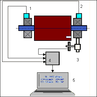
चित्र 6. बैलेंसेट-1 का उपयोग करते हुए, दो तलों में संतुलन के दौरान सेंसरों की स्थापना
1,2-वाइब्रेशन सेंसर, 3-फेज, 4-यूएसबी माप इकाई, 5-लैपटॉप
अधिकांश मामलों में गतिशील संतुलन तीन आरंभों की विधि द्वारा किया जाता है। यह विधि इस तथ्य पर आधारित है कि पहले से ज्ञात द्रव्यमान के परीक्षण भारों को क्रमशः 1 और 2 विमानों में रोटर पर श्रृंखलाबद्ध रूप से स्थापित किया जाता है; इस प्रकार कंपन मापदंडों में परिवर्तन के परिणामों के आधार पर संतुलन भारों के द्रव्यमान और स्थापना स्थान की गणना की जाती है।
भार की स्थापना के स्थान को सुधार तल कहते हैं। आमतौर पर, सुधार तल का चयन बेयरिंग सपोर्ट के उस क्षेत्र में किया जाता है जिस पर रोटर लगा होता है।
प्रारंभिक कंपन को पहले स्टार्ट पर मापा जाता है। फिर, ज्ञात द्रव्यमान का एक परीक्षण भार रोटर पर किसी एक आधार के पास स्थापित किया जाता है। फिर दूसरा स्टार्ट किया जाता है, और हम कंपन मापदंडों को मापते हैं, जो परीक्षण भार की स्थापना के कारण बदल सकते हैं। फिर पहले तल में परीक्षण भार को हटाकर दूसरे तल में स्थापित किया जाता है। तीसरा स्टार्ट-अप किया जाता है और कंपन मापदंडों को मापा जाता है। जब परीक्षण भार हटा दिया जाता है, तो प्रोग्राम स्वचालित रूप से द्रव्यमान और संतुलन भार की स्थापना के स्थान (कोण) की गणना करता है।
परीक्षण भार स्थापित करने का उद्देश्य यह निर्धारित करना है कि प्रणाली असंतुलन परिवर्तन पर कैसे प्रतिक्रिया करती है। जब हमें नमूना भारों के द्रव्यमान और उनकी स्थिति का पता चल जाता है, तो कार्यक्रम तथाकथित प्रभाव गुणांकों की गणना कर सकता है, जो दिखाते हैं कि एक ज्ञात असंतुलन के परिचय से कंपन पैरामीटर कैसे प्रभावित होते हैं। प्रभाव गुणांक स्वयं यांत्रिक प्रणाली की विशेषताएँ हैं और ये समर्थन की कठोरता तथा रोटर-समर्थन प्रणाली के द्रव्यमान (जड़त्व) पर निर्भर करते हैं।
एक ही डिज़ाइन के समान प्रकार के यंत्रों के लिए, प्रभाव गुणांक समान होंगे। आप उन्हें अपने कंप्यूटर की मेमोरी में सहेज सकते हैं और बाद में परीक्षण चलाए बिना समान प्रकार के यंत्रों को संतुलित करने के लिए उनका उपयोग कर सकते हैं, जिससे संतुलन की कार्यक्षमता में काफी सुधार होता है। हमें यह भी ध्यान देना चाहिए कि परीक्षण भारों का द्रव्यमान इस प्रकार चुना जाना चाहिए कि परीक्षण भार स्थापित करने पर कंपन पैरामीटरों में स्पष्ट परिवर्तन हो। अन्यथा, प्रभाव गुणांकों की गणना में त्रुटि बढ़ जाती है और संतुलन की गुणवत्ता बिगड़ जाती है।
Balanset-1 उपकरण के लिए दी गई गाइड में एक सूत्र दिया गया है, जिसकी सहायता से आप संतुलित रोटर के द्रव्यमान और घूर्णन गति के आधार पर परीक्षण भार का अनुमानित द्रव्यमान निर्धारित कर सकते हैं। जैसा कि चित्र 1 से स्पष्ट है, अपकेंद्री बल रेडियल दिशा में, यानी रोटर अक्ष के लंबवत कार्य करता है। इसलिए, कंपन सेंसर इस प्रकार स्थापित किए जाने चाहिए कि उनकी संवेदनशीलता अक्ष भी रेडियल दिशा में हो। आमतौर पर क्षैतिज दिशा में आधार की कठोरता कम होती है, इसलिए क्षैतिज दिशा में कंपन अधिक होता है। इसलिए, सेंसर की संवेदनशीलता बढ़ाने के लिए उन्हें इस प्रकार स्थापित किया जाना चाहिए कि उनकी संवेदनशीलता अक्ष भी क्षैतिज दिशा में हो। हालांकि इसमें कोई मूलभूत अंतर नहीं है। रेडियल दिशा में कंपन के अलावा, रोटर के घूर्णन अक्ष के अनुदिश अक्षीय दिशा में कंपन को नियंत्रित करना आवश्यक है। यह कंपन आमतौर पर असंतुलन के कारण नहीं, बल्कि अन्य कारणों से होता है, मुख्य रूप से कपलिंग के माध्यम से जुड़े शाफ्टों के गलत संरेखण और बेमेल होने के कारण। इस कंपन को संतुलन द्वारा समाप्त नहीं किया जा सकता है, इस मामले में संरेखण आवश्यक है। व्यवहार में, आमतौर पर ऐसे तंत्रों में रोटर का असंतुलन और शाफ्टों का गलत संरेखण होता है, जिससे कंपन को दूर करना बहुत मुश्किल हो जाता है। ऐसे मामलों में, पहले तंत्र को संरेखित करना और फिर उसे संतुलित करना आवश्यक होता है। (हालांकि, तीव्र टॉर्क असंतुलन होने पर, आधार संरचना के "घुमाव" के कारण अक्षीय दिशा में भी कंपन होता है)।
माप सटीकता और त्रुटि विश्लेषण
पेशेवर संतुलन कार्यों के लिए माप सटीकता को समझना महत्वपूर्ण है। बैलेंसेट-1A निम्नलिखित माप सटीकता प्रदान करता है:
| पैरामीटर | सटीकता सूत्र | उदाहरण (सामान्य मानों के लिए) |
|---|---|---|
| RMS कंपन वेग | ±(0.1 + 0.1×वीमापा) मिमी/सेकंड | 5 मिमी/सेकंड के लिए: ±0.6 मिमी/सेकंड 10 मिमी/सेकंड के लिए: ±1.1 मिमी/सेकंड |
| घूर्णन आवृत्ति | ±(1 + 0.005×एनमापा) आरपीएम | 1000 आरपीएम के लिए: ±6 आरपीएम 3000 आरपीएम के लिए: ±16 आरपीएम |
| चरण माप | ±1° | सभी गतियों पर निरंतर सटीकता |
⚠️ सटीक संतुलन के लिए महत्वपूर्ण
- !परीक्षण भार के कारण >20-30% आयाम परिवर्तन होना चाहिए और/या >20-30° चरण परिवर्तन
- !यदि परिवर्तन छोटे हैं, तो माप त्रुटियाँ काफी बढ़ जाती हैं
- !मापों के बीच कंपन आयाम और चरण स्थिरता 10-15% से अधिक भिन्न नहीं होनी चाहिए
- !यदि भिन्नता 15% से अधिक हो, तो अनुनाद स्थितियों या यांत्रिक समस्याओं की जाँच करें
संतुलन तंत्र की गुणवत्ता का आकलन करने के लिए मानदंड
रोटर (यांत्रिकी) के संतुलन की गुणवत्ता का अनुमान दो तरीकों से लगाया जा सकता है। पहला तरीका संतुलन के दौरान निर्धारित अवशिष्ट असंतुलन के मान की तुलना अवशिष्ट असंतुलन के लिए निर्धारित सहनशीलता से करने पर आधारित है। मानक में स्थापित विभिन्न श्रेणियों के रोटरों के लिए निर्दिष्ट सहनशीलताएँ ISO 21940-11 «Mechanical vibration – Rotor balancing – Part 11: Procedures and tolerances for rotors with rigid behaviour» (पूर्व में ISO 1940-1).
हालाँकि, इन सहनशीलताओं का कार्यान्वयन न्यूनतम कंपन स्तर की प्राप्ति से जुड़े तंत्र की परिचालन विश्वसनीयता की पूरी गारंटी नहीं दे सकता। ऐसा इसलिए है क्योंकि तंत्र का कंपन न केवल उसके रोटर के अवशिष्ट असंतुलन से जुड़े बल की मात्रा से निर्धारित होता है, बल्कि कई अन्य मापदंडों पर भी निर्भर करता है, जिनमें शामिल हैं: तंत्र के संरचनात्मक तत्वों की कठोरता K, उसका द्रव्यमान M, अवमंदन गुणांक और गति। इसलिए, कुछ मामलों में तंत्र के गतिशील गुणों (इसके संतुलन की गुणवत्ता सहित) का आकलन करने के लिए, तंत्र के अवशिष्ट कंपन के स्तर का आकलन करने की सिफारिश की जाती है, जिसे कई मानकों द्वारा नियंत्रित किया जाता है।
यंत्रों के अनुमेय कम्पन स्तरों को विनियमित करने वाला सबसे सामान्य मानक है ISO 10816-3:2009 का पूर्वावलोकन: यांत्रिक कंपन – गैर-घूर्णनशील भागों पर मापन द्वारा मशीन कंपन का मूल्यांकन – भाग 3: 15 किलोवाट से अधिक नाममात्र शक्ति और 120 आर/मिनट से 15,000 आर/मिनट के बीच नाममात्र गति वाली औद्योगिक मशीनें, जब उनका मापन यथास्थान किया जाता है।»
इसकी मदद से आप सभी प्रकार की मशीनों पर, उनकी विद्युत चालक की शक्ति को ध्यान में रखते हुए, सहिष्णुता निर्धारित कर सकते हैं।
इस सार्वभौमिक मानक के अतिरिक्त, विशिष्ट प्रकार के तंत्रों के लिए कई विशेषीकृत मानक विकसित किए गए हैं। उदाहरण के लिए,
- आईएसओ 14694:2003 "औद्योगिक पंखे - संतुलन गुणवत्ता और कंपन स्तरों के लिए विनिर्देश""
- आईएसओ 7919-1-2002 "अप्रतिवर्ती गति के बिना मशीनों का कंपन। घूर्णनशील शाफ्टों पर मापन और मूल्यांकन मानदंड। सामान्य मार्गदर्शन।""
🛡️ यूरोपीय संघ के अनुपालन के लिए महत्वपूर्ण सुरक्षा संबंधी विचार
- !जोखिम मूल्यांकन आवश्यक: परिचालनों को संतुलित करने से पहले EN ISO 12100 जोखिम मूल्यांकन करें
- !योग्य कार्मिक: केवल प्रशिक्षित और प्रमाणित कर्मियों को ही संतुलन संचालन करना चाहिए
- !व्यक्तिगत सुरक्षा उपकरण: हमेशा EN 166 (नेत्र सुरक्षा) और EN 352 (श्रवण सुरक्षा) के अनुसार उपयुक्त PPE का उपयोग करें
- !आपातकालीन कार्यवाही: स्पष्ट आपातकालीन शटडाउन प्रक्रियाएं स्थापित करें और सुनिश्चित करें कि सभी ऑपरेटर उनसे परिचित हों
- !दस्तावेज़ीकरण: पता लगाने और अनुपालन के लिए सभी संतुलन कार्यों का विस्तृत रिकॉर्ड बनाए रखें
यूरोपीय संघ के अनुपालन और सुरक्षा संबंधी जानकारी
अनुपालन की घोषणा
बैलेंसेट-1ए पोर्टेबल बैलेंसर निम्नलिखित यूरोपीय संघ के निर्देशों और मानकों का अनुपालन करता है:
| यूरोपीय संघ के निर्देश/मानक | अनुपालन विवरण | सुरक्षा आवश्यकताओं |
|---|---|---|
| मशीनरी निर्देश 2006/42/EC | मशीनरी और सुरक्षा घटकों के लिए सुरक्षा आवश्यकताएँ | जोखिम मूल्यांकन, सुरक्षा निर्देश, CE अंकन |
| ईएमसी निर्देश 2014/30/ईयू | विद्युत चुम्बकीय संगतता आवश्यकताएँ | विद्युत चुम्बकीय हस्तक्षेप के प्रति प्रतिरक्षा |
| RoHS निर्देश 2011/65/EU | घातक पदार्थों पर प्रतिबन्ध | सीसा-मुक्त, पारा-मुक्त, कैडमियम-मुक्त घटक |
| WEEE निर्देश 2012/19/EU | अपशिष्ट विद्युत और इलेक्ट्रॉनिक उपकरण | उचित निपटान और पुनर्चक्रण प्रक्रियाएं |
| ईएन आईएसओ 12100:2010 | मशीनरी की सुरक्षा - डिजाइन के लिए सामान्य सिद्धांत | जोखिम मूल्यांकन और जोखिम न्यूनीकरण |
| एन 60825-1:2014 | लेजर उत्पादों की सुरक्षा - भाग 1 | कक्षा 2 लेज़र सुरक्षा आवश्यकताएँ |
| ईएन आईएसओ 14120:2015 | गार्ड - सामान्य आवश्यकताएँ | घूर्णन मशीनरी के खतरों से सुरक्षा |
विद्युत सुरक्षा मानक
- ✓एन 61010-1: मापन, नियंत्रण और प्रयोगशाला उपयोग के लिए विद्युत उपकरणों की सुरक्षा आवश्यकताएँ
- ✓एन 60950-1: सूचना प्रौद्योगिकी उपकरण सुरक्षा (USB संचालित उपकरण)
- ✓आईईसी 61000 श्रृंखला: विद्युत चुम्बकीय संगतता मानक
- ✓ऑपरेटिंग वोल्टेज: 5V डीसी USB के माध्यम से (अतिरिक्त कम वोल्टेज)
- ✓बिजली की खपत: < 2.5W
- ✓संरक्षण वर्ग: IP54 (धूल से संरक्षित; पानी के छींटों के प्रतिरोधी)
घूर्णन उपकरण सुरक्षा
⚠️ अनिवार्य सुरक्षा प्रक्रियाएं (EN ISO 12100)
चेतावनी: घूर्णनशील मशीनों के साथ काम करते समय, निम्नलिखित सुरक्षा आवश्यकताओं का पालन करें:
- !एन आईएसओ 14118: अचानक चालू होने से बचाव - सेंसर लगाने से पहले लॉकआउट/टैगआउट प्रक्रियाओं का उपयोग करें
- !ईएन आईएसओ 14120: सुनिश्चित करें कि सभी घूमने वाले उपकरण ठीक से सुरक्षित हों।
- !ईएन आईएसओ 13857: घूमते हुए भागों से न्यूनतम सुरक्षित दूरी बनाए रखें (शरीर के लिए 500 मिमी, उंगलियों के लिए 120 मिमी)
- !व्यक्तिगत सुरक्षा उपकरण: EN 166 के अनुसार सुरक्षा चश्मे पहनें, EN 352 के अनुसार कान की सुरक्षा के लिए उपकरण पहनें और ढीले कपड़े पहनने से बचें।
- !गतिमान मशीनों पर कभी भी सेंसर या परीक्षण भार न लगाएँ
- !सेंसर स्थापना से पहले सुनिश्चित करें कि मशीन पूरी तरह से बंद और सुरक्षित है
- !आपातकालीन रोक: ऑपरेटर की स्थिति से 3 मीटर के भीतर पहुंच योग्य होना चाहिए
- !केवल योग्य और प्रमाणित कर्मियों को ही संतुलन संचालन करना चाहिए
लेजर सुरक्षा वर्गीकरण
🔴 क्लास 2 लेजर डिवाइस (EN 60825-1:2014)
- तरंगदैर्ध्य: 650 एनएम (लाल दृश्य प्रकाश)
- अधिकतम आउटपुट शक्ति: < 1 मेगावाट
- बीम व्यास: 100 मिमी की दूरी पर 3-5 मिमी
- विचलन: < 1.5 एमआरएडी
- सुरक्षा वर्गीकरण: क्षणिक जोखिम के लिए आँख सुरक्षित (< 0.25 सेकंड)
- आवश्यक लेबलिंग: ""लेजर विकिरण - किरण में सीधे न देखें - श्रेणी 2 का लेजर उत्पाद""
- प्रवेश वर्ग: अप्रतिबंधित (सामान्य प्रवेश की अनुमति)
लेज़र सुरक्षा प्रक्रियाएँ:
- कभी भी जानबूझकर लेज़र बीम में न देखें
- लेज़र को व्यक्तियों, वाहनों या विमानों पर लक्षित न करें
- ऑप्टिकल उपकरणों (दूरबीन, दूरबीन) से लेजर बीम देखने से बचें
- चमकदार सतहों से होने वाले परावर्तनों से सावधान रहें
- उपयोग में न होने पर लेज़र बंद कर दें
- आँखों के संपर्क में आने की किसी भी घटना की तुरंत रिपोर्ट करें
- लंबे समय तक एक्सपोजर के लिए लेजर सुरक्षा चश्मे (650nm पर OD 2+) का उपयोग करें
माप सटीकता और अंशांकन
| पैरामीटर | शुद्धता | अंशांकन आवृत्ति |
|---|---|---|
| कंपन आयाम | ±5% रीडिंग | सालाना या 1000 घंटे के बाद |
| चरण माप | ±1° | हर साल |
| घूर्णन गति | ±0.1% रीडिंग | हर साल |
| सेंसर संवेदनशीलता | 13 mV/(mm/s) ±10% | सेंसर बदलते समय |
पर्यावरण अनुपालन
- ✓परिचालन वातावरण: 5°C से 50°C, < 85% RH गैर-संघनक
- ✓भंडारण वातावरण: -20°C से 70°C, < 95% RH गैर-संघनक
- ✓ऊंचाई: समुद्र तल से 2000 मीटर ऊपर तक
- ✓कंपन प्रतिरोध: आईईसी 60068-2-6 (10-500 हर्ट्ज, 2जी त्वरण)
- ✓आघात प्रतिरोध: IEC 60068-2-27 (15g, 11ms अवधि)
- ✓आईपी रेटिंग: IP54 (धूल से संरक्षित; पानी के छींटों के प्रतिरोधी)
संचालन आवश्यकताएँ
- ✓ऑपरेटरों को यूरोपीय संघ के मानकों के अनुसार मशीनरी सुरक्षा में प्रशिक्षित होना चाहिए
- ✓उपयोग से पहले EN ISO 12100 के अनुसार जोखिम मूल्यांकन आवश्यक है
- ✓निर्माता के विनिर्देशों के अनुसार उपकरण का रखरखाव करें
- ✓किसी भी सुरक्षा संबंधी घटना या उपकरण की खराबी की तुरंत रिपोर्ट करें
- ✓पता लगाने की क्षमता के लिए सभी संतुलन कार्यों का विस्तृत रिकॉर्ड बनाए रखें
दस्तावेज़ीकरण आवश्यकताएँ
यूरोपीय संघ के अनुपालन के लिए, निम्नलिखित दस्तावेज़ बनाए रखें:
- ✓EN ISO 12100 के अनुसार जोखिम मूल्यांकन दस्तावेज़
- ✓ऑपरेटर प्रशिक्षण रिकॉर्ड और प्रमाणन
- ✓उपकरण अंशांकन और रखरखाव लॉग
- ✓तिथियों, ऑपरेटरों और परिणामों के साथ संतुलन संचालन के रिकॉर्ड
- ✓सुरक्षा घटना रिपोर्ट और सुधारात्मक कार्रवाई
- ✓उपकरण संशोधन या मरम्मत दस्तावेज़ीकरण
तकनीकी सहायता और सेवा
तकनीकी सहायता, अंशांकन सेवाओं और स्पेयर पार्ट्स के लिए:
- ✓निर्माता: वाइब्रोमेरा
- ✓जगह: नारवा, एस्टोनिया (EU)
- ✓वेबसाइट: https://vibromera.eu
- ✓सहायक भाषाएँ: सभी प्रमुख भाषाएँ उपलब्ध हैं। लिखित संचार की सुविधा उपलब्ध है।
- ✓सेवा कवरेज: दुनिया भर में शिपिंग उपलब्ध है
- ✓वारंटी: खरीद की तारीख से 12 महीने
- ✓अंशांकन सेवा: अधिकृत सेवा केंद्रों के माध्यम से उपलब्ध