Pengimbangan rotor: ketidakseimbangan statik dan dinamik, resonans dan prosedur praktikal
Panduan ini menerangkan pengimbangan rotor untuk pemutar tegar: maksud "ketidakseimbangan", bagaimana ketidakseimbangan statik dan dinamik berbeza, mengapa resonans dan ketaklinearan boleh menghalang hasil yang berkualiti dan bagaimana pengimbangan biasanya dilakukan dalam satu atau dua satah pembetulan.


Kandungan
- Apakah itu rotor dan apakah yang betul dengan pengimbangan?
- Jenis-jenis rotor dan jenis ketidakseimbangan
- Getaran mekanisme: apa yang boleh dan tidak boleh disingkirkan oleh pengimbangan
- Resonans: faktor yang menghalang keseimbangan
- Model linear vs. tak linear: apabila pengiraan berhenti berfungsi
- Balancing devices and balancing machines
- Mengimbangi rotor tegar (nota praktikal)
- Cara pengimbangan dinamik dilakukan (kaedah tiga larian)
- Kriteria untuk menilai kualiti pengimbangan
- Piawaian dan rujukan
- Soalan Lazim
Apakah itu rotor dan apakah yang betul dengan pengimbangan?
The rotor is a body which rotates about some axis and is held by its bearing surfaces in the supports. The bearing surfaces of the rotor transmit loads to the supports via rolling or sliding bearings. The bearing surfaces are the surfaces of the trunnions or the surfaces that replace them.
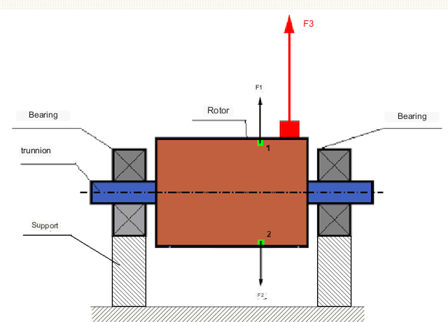
Dalam rotor yang seimbang sempurna, jisimnya diagihkan secara simetri mengelilingi paksi putaran, iaitu, mana-mana elemen rotor boleh dipadankan dengan elemen lain yang terletak secara simetri mengelilingi paksi putaran. Dalam rotor yang seimbang, daya emparan yang bertindak pada mana-mana elemen rotor diseimbangkan oleh daya emparan yang bertindak pada elemen simetri tersebut. Contohnya, daya emparan F1 dan F2, yang sama magnitud dan bertentangan arah, bertindak pada elemen 1 dan 2 (ditanda hijau dalam Rajah 1). Ini adalah benar untuk semua elemen rotor simetri, dan dengan itu jumlah daya emparan yang bertindak pada rotor ialah 0 dan rotor seimbang.
Tetapi jika simetri rotor rosak (elemen asimetri ditanda dengan warna merah pada Rajah 1), maka daya emparan F3 yang tidak seimbang bertindak pada rotor. Apabila berputar, daya ini berubah arah dengan putaran rotor. Beban dinamik yang terhasil daripada daya ini dihantar ke galas, mengakibatkan haus dan lusuh yang dipercepatkan.
In addition, under the influence of this variable in direction force there is a cyclic deformation of supports and foundation, on which the rotor is fixed, i.e. there is vibration. In order to eliminate rotor imbalance and the accompanying vibration, balancing masses must be installed to restore symmetry to the rotor.
Rotor balancing is an operation to correct imbalance by adding balancing masses.
The task of balancing is to find the size and location (angle) of one or more balancing masses.
Jenis-jenis rotor dan jenis ketidakseimbangan
Dengan mengambil kira kekuatan bahan rotor dan magnitud daya emparan yang bertindak ke atasnya, rotor boleh dibahagikan kepada dua jenis - rotor tegar dan rotor fleksibel.
Rigid rotors deform insignificantly under action of centrifugal force at working modes and influence of this deformation in calculations can be neglected.
Deformasi rotor fleksibel tidak lagi boleh diabaikan. Deformasi rotor fleksibel merumitkan penyelesaian masalah pengimbangan dan memerlukan aplikasi model matematik lain berbanding masalah pengimbangan rotor tegar. Perlu diingatkan bahawa rotor yang sama pada kelajuan rendah boleh bertindak sebagai tegar, dan pada kelajuan tinggi - sebagai fleksibel. Berikutnya, kita hanya akan mempertimbangkan pengimbangan rotor tegar.
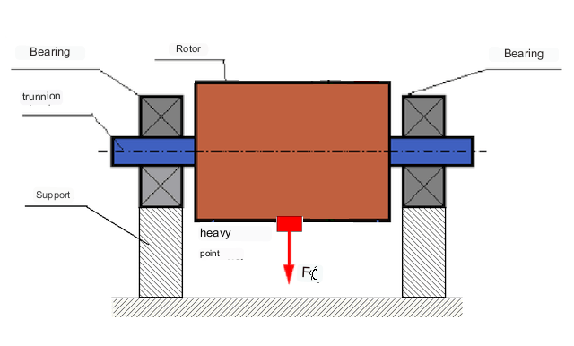
Bergantung pada taburan jisim tidak seimbang di sepanjang panjang rotor, dua jenis ketidakseimbangan boleh dibezakan - statik dan dinamik (seketika). Sehubungan itu, pengimbangan rotor statik dan dinamik dirujuk. Ketidakseimbangan rotor statik berlaku tanpa putaran rotor, iaitu dalam statik, apabila rotor diterbalikkan oleh graviti dengan "titik beratnya" ke bawah. Satu contoh rotor dengan ketidakseimbangan statik ditunjukkan dalam Rajah 2.
Dynamic unbalance occurs only when the rotor is rotating.
An example of a rotor with dynamic unbalance is shown in Fig. 3.
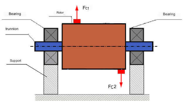
Dalam kes ini, jisim yang sama M1 dan M2 yang tidak seimbang berada dalam satah yang berbeza - di tempat yang berbeza di sepanjang rotor. Dalam kedudukan statik, iaitu apabila rotor tidak berputar, hanya graviti yang bertindak pada rotor dan jisim-jisim tersebut mengimbangi antara satu sama lain. Dalam dinamik, apabila rotor berputar, daya emparan Fc1 dan Fc2 mula bertindak pada jisim M1 dan M2. Daya-daya ini sama magnitudnya dan bertentangan arahnya. Walau bagaimanapun, memandangkan ia dikenakan pada tempat yang berbeza di sepanjang aci dan tidak berada pada garis yang sama, daya-daya ini tidak mengimbangi antara satu sama lain. Daya Fc1 dan Fc2 menghasilkan tork yang dikenakan pada rotor. Oleh itu, ketidakseimbangan ini juga dipanggil ketidakseimbangan momen. Sehubungan itu, daya emparan yang tidak terkompensasi bertindak pada kedudukan galas, yang boleh melebihi nilai yang dikira dan mengurangkan hayat perkhidmatan galas.
Oleh kerana jenis ketidakseimbangan ini hanya berlaku secara dinamik semasa putaran rotor, ia dipanggil ketidakseimbangan dinamik. Ia tidak boleh dibetulkan dalam keadaan statik dengan mengimbangi "atas pisau" atau kaedah yang serupa. Untuk menghapuskan ketidakseimbangan dinamik, dua pemberat pampasan mesti dipasang, yang menghasilkan momen yang sama magnitud dan bertentangan arah dengan momen yang timbul daripada jisim M1 dan M2. Jisim pampasan tidak perlu ditetapkan bertentangan dan sama magnitud dengan jisim M1 dan M2. Perkara utama ialah ia menghasilkan momen yang mengimbangi sepenuhnya momen ketidakseimbangan.
Secara amnya, jisim M1 dan M2 mungkin tidak sama antara satu sama lain, jadi akan terdapat gabungan ketidakseimbangan statik dan dinamik. Secara teorinya, terbukti bahawa bagi rotor tegar, dua pemberat yang dijarakkan di sepanjang rotor adalah perlu dan mencukupi untuk menghapuskan ketidakseimbangannya. Pemberat ini akan mengimbangi kedua-dua tork yang terhasil daripada ketidakseimbangan dinamik dan daya emparan yang terhasil daripada asimetri jisim relatif kepada paksi rotor (ketidakseimbangan statik). Biasanya, ketidakseimbangan dinamik adalah ciri-ciri rotor yang panjang, seperti aci, dan ketidakseimbangan statik adalah ciri-ciri rotor yang sempit. Walau bagaimanapun, jika rotor yang sempit condong relatif kepada paksi, atau berubah bentuk ("rajah lapan"), maka ketidakseimbangan dinamik akan sukar dihapuskan (lihat Rajah 4), kerana dalam kes ini, sukar untuk memasang pemberat pembetulan yang mencipta momen pampasan yang diperlukan.
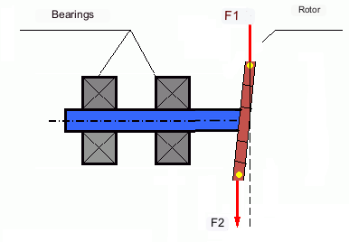
The forces F1 and F2 do not lie on the same line and do not compensate each other.
Disebabkan lengan untuk menghasilkan tork adalah kecil disebabkan oleh rotor yang sempit, pemberat pembetulan yang besar mungkin diperlukan. Walau bagaimanapun, ini juga mengakibatkan "ketidakseimbangan teraruh" disebabkan oleh ubah bentuk rotor yang sempit oleh daya emparan daripada pemberat pembetulan. (Lihat sebagai contoh "Arahan metodologi untuk mengimbangi rotor tegar (mengikut ISO 22061-76)". Seksyen 10. SISTEM SOKONGAN ROTOR. )
This is noticeable for narrow impellers of fans, in which, in addition to force unbalance, aerodynamic unbalance is also active. And it should be understood that aerodynamic unbalance, or rather aerodynamic force is directly proportional to angular speed of the rotor, and for its compensation the centrifugal force of correcting mass, which is proportional to the square of angular speed, is used. Therefore, the balancing effect can only take place at a specific balancing frequency. At other rotational frequencies there is an additional error.
The same can be said of the electromagnetic forces in an electric motor, which are also proportional to angular velocity. So it is not possible to eliminate all causes of vibration in a machine by balancing.
Getaran mekanisme
Vibration is the reaction of the mechanism design to the effects of a cyclic excitatory force. This force can be of different nature.
Daya emparan yang terhasil daripada rotor yang tidak seimbang ialah daya tidak terkompensasi yang bertindak pada "titik berat". Daya inilah dan getaran yang disebabkan olehnya yang boleh dihapuskan dengan mengimbangi rotor.
Daya interaksi bersifat "geometri" yang timbul daripada ralat pembuatan dan pemasangan bahagian-bahagian yang sepadan. Daya-daya ini boleh, sebagai contoh, timbul akibat ketidakbulatan leher aci, ralat dalam profil gigi dalam gear, kealunan laluan perlumbaan galas, ketidaksejajaran aci yang sepadan, dsb. Dalam kes ketiadaan bulatan jurnal, paksi aci akan dialihkan bergantung pada sudut putaran aci. Walaupun getaran ini juga berlaku pada kelajuan rotor, hampir mustahil untuk menghapuskannya dengan mengimbangi.
Aerodynamic forces resulting from the rotation of the impellers of fans and other vane mechanisms. Hydrodynamic forces resulting from the rotation of impellers of hydraulic pumps, turbines, etc.
Electromagnetic forces resulting from the operation of electrical machines, e.g. asymmetric rotor windings, short-circuited windings, etc.
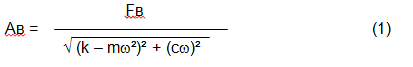
The magnitude of the vibration (e.g. its amplitude Av) depends not only on the excitatory force Fv acting on the mechanism with circular frequency ω, but also on the rigidity k of the mechanism, its mass m , as well as the damping coefficient C.
Various types of sensors can be used to measure vibration and balance mechanisms, including:
- absolute vibration sensors designed to measure vibration acceleration (accelerometers) and vibration velocity sensors;
- sensor getaran relatif - arus pusar atau kapasitif, direka untuk mengukur anjakan getaran;
- dalam beberapa kes (apabila reka bentuk mekanisme membenarkannya), sensor daya juga boleh digunakan untuk menilai beban getarannya; khususnya, ia digunakan secara meluas untuk mengukur beban getaran sokongan mesin pengimbang galas keras.
So, vibration is the reaction of a machine to the action of external forces. The magnitude of vibration depends not only on the magnitude of the force acting on the mechanism, but also on the rigidity of the mechanism design. One and the same force can lead to different vibrations. In a hard-bearing machine, even if the vibration is small, the bearings may be subjected to significant dynamic loads. This is why force rather than vibration sensors (vibration accelerometers) are used when balancing hard-bearing machines.
Vibration sensors are used on mechanisms with relatively pliable supports, when the action of unbalanced centrifugal forces leads to a noticeable deformation of supports and vibration. Force sensors are used for rigid supports, when even significant forces due to unbalance do not lead to significant vibration.
Resonance is a factor that prevents balancing
Earlier we mentioned that rotors are divided into rigid and flexible. Stiffness or flexibility of rotor should not be confused with stiffness or mobility of supports (foundation) on which the rotor is installed. A rotor is considered rigid when its deformation (bending) under the action of centrifugal forces can be neglected. Deformation of flexible rotor is relatively large and cannot be neglected.
In this article, we consider only the balancing of rigid rotors. A rigid (non-deformable) rotor can in turn be mounted on rigid or movable (pliable) supports. It is clear that this stiffness/suspendability of supports is also relative, depending on rotor speed and magnitude of resulting centrifugal forces. A conditional boundary is the frequency of natural vibrations of the rotor supports.
For mechanical systems, the shape and frequency of natural vibrations are determined by the mass and the elasticity of the elements of mechanical system. That is, the frequency of natural vibrations is an internal characteristic of the mechanical system and does not depend on external forces. Being deflected from the state of equilibrium, supports due to elasticity tend to return to the position of equilibrium. But due to the inertia of the massive rotor, this process is in the nature of damped oscillations. These vibrations are the natural vibrations of the rotor-support system. Their frequency depends on the ratio of the mass of the rotor to the elasticity of the supports.
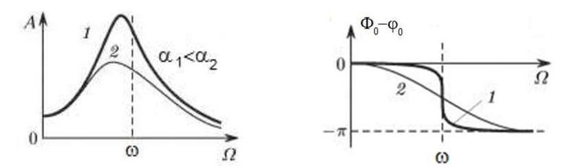
When the rotor begins to rotate and the frequency of its rotation approaches the frequency of natural vibrations, the amplitude of vibration increases sharply, which can lead to the destruction of the structure.
The phenomenon of mechanical resonance occurs. In the area of resonance, a change of rotation speed by 100 rpm may lead to an increase in vibration by tens of times. At the same time (in the resonance area) the vibration phase changes by 180°.
If the design of the mechanism is unsuccessful and the operating frequency of the rotor is close to the frequency of natural vibrations, then the operation of the mechanism becomes impossible because of the inadmissibly high vibration. This is not possible in the usual way, since even a small change in speed will cause a drastic change in the vibration parameters. For balancing in the area of resonance, special methods not considered in this article are used.
It is possible to determine the frequency of natural vibrations of the mechanism at coasting (at switching off the rotor rotation) or by the shock method with the subsequent spectral analysis of the system response to the shock.
For mechanisms, which working frequency of rotation is above the resonance frequency, i.e. working in the resonance regime, the supports are considered to be moving and for measurement are used vibration sensors, mainly vibroacelerometers, measuring acceleration of structural elements. For mechanisms operating in preresonant mode, the supports are considered rigid. In this case, force sensors are used.
Linear and nonlinear models of a mechanical system. Non-linearity is a factor that prevents balancing
When balancing rigid rotors, mathematical models called linear models are used for balancing calculations. A linear model means that in such a model, one quantity is proportional (linear) to the other. For example, if the uncompensated mass on the rotor is doubled, then the vibration value will also be doubled. For rigid rotors, a linear model can be used, since they do not deform.
For flexible rotors, the linear model can no longer be used. For a flexible rotor, if the mass of the heavy point increases during rotation, additional deformation will occur, and in addition to the mass, the radius of the location of the heavy point will also increase. Therefore, for a flexible rotor, the vibration will increase more than twofold, and the usual methods of calculation will not work.
Also, the change of elasticity of supports at their large deformations, for example, when at small deformations of supports some structural elements work, and at large ones other structural elements are involved. This is why you cannot balance mechanisms that are not fixed on a foundation, but, for example, simply placed on the floor. With significant vibrations, the force of the imbalance can pull the mechanism off the floor, thereby significantly changing the stiffness characteristics of the system. Motor feet must be securely fastened, bolt mounts must be tightened, washer thickness must provide sufficient mounting rigidity, etc. If the bearings are broken, significant shaft misalignment and shocks are possible, which will also result in poor linearity and an inability to perform a quality balance.
Balancing devices and balancing machines
Seperti yang dinyatakan di atas, pengimbangan ialah proses menjajarkan paksi inersia pusat utama dengan paksi putaran rotor.
This process can be performed by two methods.
The first method involves machining the rotor trunnions in such a way that the axis passing through the centers of the trunnions cross section with the main central axis of inertia of the rotor. Such a technique is rarely used in practice and will not be discussed in detail in this article.
The second (most common) method involves moving, installing or removing correction weights on the rotor, which are placed so that the axis of inertia of the rotor is as close to its axis of rotation as possible.
Moving, adding or removing correction weights during balancing may be accomplished by various technological operations including: drilling, milling, surfacing, welding, screwing or unscrewing, laser or electron beam burning, electrolysis, electromagnetic surfacing, etc.
The balancing process can be accomplished in two ways:
- balancing of assembled rotors (in their own bearings) using balancing machines;
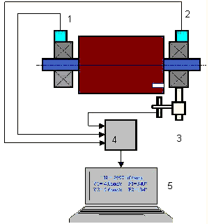
- balancing of rotors on balancing machines. For balancing of rotors in their own bearings usually used specialized balancing devices (kits), which allow to measure the vibration of the balanced rotor at its frequency of rotation in vector form, i.e. to measure both the amplitude and the phase of vibration. At present, the above devices are manufactured on the basis of microprocessor technology and (apart from vibration measurement and analysis) provide automatic calculation of parameters of correcting weights, which should be installed on the rotor to compensate its unbalance.
These devices include:
- a measuring and computing unit based on a computer or industrial controller;
- Two (or more) vibration sensors;
- A phase angle sensor;
- accessories for mounting the sensors on the site;
- specialized software, designed to perform a full cycle of rotor vibration parameters measurement in one, two or more correction planes.
Two types of balancing machines are currently the most common:
- Soft-bearings machines (with soft supports);
- Hard-bearings machines (with rigid supports).
Mesin galas lembut mempunyai sokongan yang agak lentur, contohnya, berdasarkan spring rata. Kekerapan getaran semula jadi sokongan ini biasanya 2-3 kali lebih rendah daripada frekuensi putaran rotor pengimbang, yang dipasang padanya. Sensor getaran (pecutan, sensor halaju getaran, dll.) biasanya digunakan semasa mengukur getaran sokongan praresonan mesin.
Pre-resonance balancing machines use relatively rigid supports, whose natural frequencies of vibration should be 2-3 times higher than the rotation frequency of the rotor being balanced. Force transducers are usually used to measure the vibration load of the preresonance machine supports.
Kelebihan mesin pengimbangan pra-resonans ialah pengimbangan padanya boleh dilakukan pada kelajuan rotor yang agak rendah (sehingga 400 - 500 rpm), yang sangat memudahkan reka bentuk mesin dan asasnya, dan meningkatkan produktiviti dan keselamatan pengimbangan.
Balancing rigid rotors
Important!
- Balancing only eliminates vibration caused by asymmetrical distribution of the rotor mass relative to its rotational axis. Other types of vibration are not eliminated by balancing!
- Technical mechanisms, whose design ensures the absence of resonances at the operating frequency of rotation, reliably fixed on the foundation, installed in serviceable bearings, are subject to balancing.
- Defective machinery must be repaired before balancing. Otherwise, quality balancing is not possible.
Balancing is no substitute for repair!
The main task of balancing is to find the mass and location of compensating weights that are subject to balancing centrifugal forces.
As mentioned above, for rigid rotors, it is generally necessary and sufficient to install two compensating weights. This will eliminate both static and dynamic unbalance of the rotor. The general scheme for measuring vibration during balancing is as follows.
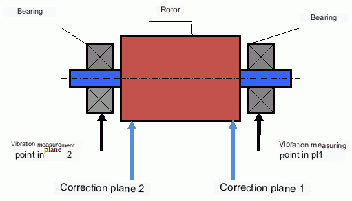
Vibration sensors are installed on the bearing supports at points 1 and 2. A revolution marker is attached to the rotor, usually with reflective tape. The RPM mark is used by the laser tachometer to determine the rotor speed and phase of the vibration signal.
Cara pengimbangan dinamik dilakukan (kaedah tiga larian)
In most cases dynamic balancing is carried out by the method of three starts. The method is based on the fact that test weights of known weight are placed on the rotor in series in plane 1 and 2 and the weights and the location of the balancing weights are calculated based on the results of changes in the vibration parameters.
The place of installation of weights is called the correction plane. Usually the correction planes are selected in the area of the bearing supports on which the rotor is installed.
At the first start-up the initial vibration is measured. Then a test weight of known weight is placed on the rotor closer to one of the bearings. A second start-up is carried out and the vibration parameters are measured, which should change due to the test weight installation. Then the test weight in the first plane is removed and installed in the second plane. A third test run is performed and the vibration parameters are measured. The test weight is removed and the software automatically calculates the masses and installation angles of the balance weights.
The point of installing the test weights is to determine how the system reacts to changes in imbalance. The weights and locations of the test weights are known, so the software can calculate so called influence coefficients, showing how introducing a known imbalance affects the vibration parameters. The influence coefficients are characteristics of the mechanical system itself and depend on the rigidity of the supports and the mass (inertia) of the rotor-support system.
For the same type of mechanisms of the same design the influence coefficients will be close. It is possible to save them in the computer memory and use them for balancing of the same-type mechanisms without test runs, which significantly increases the productivity of balancing. Note that the mass of test weights should be chosen such that the vibration parameters change noticeably when test weights are installed. Otherwise, the error of calculation of influence coefficients increases and the quality of balancing deteriorates.
As you can see from Fig. 1, the centrifugal force acts in the radial direction, i.e. perpendicular to the rotor axis. Therefore, the vibration sensors must be installed so that their axis of sensitivity also points in the radial direction. Usually, the stiffness of the foundation in the horizontal direction is less, so the vibration in the horizontal direction is higher. Therefore, in order to increase the sensitivity, the sensors should be installed so that their axis of sensitivity is also directed horizontally. Although there is no fundamental difference. In addition to vibration in the radial direction, vibration in the axial direction, along the rotor rotation axis, must be monitored. This vibration is usually not caused by unbalance, but by other causes, mainly related to misalignment and misalignment of the shafts connected through the coupling.
Getaran ini tidak dapat dihapuskan dengan pengimbangan, yang mana penjajaran diperlukan. Dalam praktiknya, mesin sedemikian biasanya mempunyai ketidakseimbangan rotor dan ketidakseimbangan aci, yang menjadikan tugas menghapuskan getaran jauh lebih sukar. Dalam kes sedemikian, adalah perlu untuk memusatkan mesin terlebih dahulu dan kemudian mengimbanginya. (Walaupun dengan ketidakseimbangan tork yang kuat, getaran juga berlaku dalam arah paksi disebabkan oleh "putaran" struktur asas.)
Artikel berkaitan (contoh penyangga pengimbang)
- Penyangga imbangan dengan sokongan lembut
- Mengimbangi rotor motor elektrik
- Simple but effective balancing stands
Kriteria untuk menilai kualiti mekanisme pengimbangan
The balancing quality of rotors (mechanisms) can be evaluated in two ways. The first method involves comparing the amount of residual unbalance determined during the balancing process with the tolerance for residual unbalance. These tolerances for the different rotor classes are specified in ISO 1940-1-2007. Part 1. Definition of allowable unbalance.
However, compliance with the specified tolerances cannot fully guarantee the operational reliability of the mechanism, associated with the achievement of the minimum level of its vibration. This is explained by the fact that the magnitude of vibration of the mechanism is determined not only by the magnitude of the force associated with the residual unbalance of its rotor, but also depends on several other parameters, including: the rigidity k of the mechanism structural elements, its mass m, the damping factor, as well as the rotation frequency. Therefore, to estimate dynamic qualities of the mechanism (including quality of its balance) in a number of cases it is recommended to estimate the level of residual vibration of the mechanism, which is regulated by a number of standards.
The most common standard, which regulates the admissible levels of vibration of mechanisms is ISO 10816-3-2002. With its help, it is possible to set tolerances for any type of machines, taking into account the power of their electric drive.
In addition to this universal standard, there is a number of specialized standards developed for specific types of machines. For example, 31350-2007 , ISO 7919-1-2002, etc.
Piawaian dan rujukan
- ISO 1940-1:2007. Getaran. Keperluan untuk kualiti pengimbangan rotor tegar. Bahagian 1. Penentuan ketidakseimbangan yang dibenarkan.
- ISO 10816-3:2009. Getaran mekanikal — Penilaian getaran mesin melalui pengukuran pada bahagian yang tidak berputar — Bahagian 3: Mesin industri dengan kuasa nominal melebihi 15 kW dan kelajuan nominal antara 120 r/min dan 15 000 r/min apabila diukur di situ.
- ISO 14694:2003. Kipas industri — Spesifikasi untuk kualiti keseimbangan dan tahap getaran.
- ISO 7919-1:2002. Getaran mesin tanpa gerakan salingan — Pengukuran pada aci berputar dan kriteria penilaian — Panduan umum.
Soalan Lazim
Adakah pengimbangan menghapuskan semua getaran?
Tidak. Pengimbangan menghilangkan getaran yang disebabkan oleh taburan jisim rotor yang tidak simetri berbanding paksi putarannya. Getaran daripada ketidaksejajaran, kecacatan galas, daya aerodinamik/hidrodinamik, daya elektromagnet dan punca lain memerlukan tindakan diagnostik dan pembetulan yang berasingan.
Mengapakah pengimbangan boleh gagal berhampiran resonans?
Perubahan kelajuan yang kecil dan hampir resonans boleh menyebabkan perubahan besar dalam amplitud getaran dan anjakan fasa 180°. Dalam keadaan sedemikian, keputusan pengukuran menjadi tidak stabil dan prosedur pengimbangan konvensional mungkin tidak dapat bertemu tanpa kaedah khas.
Bilakah anda memerlukan pengimbangan satu satah vs. dua satah?
Bagi rotor tegar, dua pemberat yang dipisahkan sepanjang panjang rotor secara amnya diperlukan dan mencukupi untuk menghapuskan gabungan ketidakseimbangan statik dan dinamik. Rotor sempit selalunya mempamerkan ketidakseimbangan statik, tetapi ubah bentuk dan geometri boleh memperkenalkan komponen dinamik yang mungkin memerlukan pembetulan dua satah.
Apakah yang perlu dilakukan sebelum melakukan pengimbangan?
Pastikan mesin boleh diservis: pemasangan yang boleh dipercayai pada asas, galas yang sihat, tiada kelonggaran yang teruk dan tiada punca ketidaklinearan yang jelas. Pengimbangan bukanlah pengganti pembaikan.
Kesimpulan penting
- Pengimbangan membetulkan pengujaan (emparan) yang berkaitan dengan jisim; ia tidak menyelesaikan ketidaksejajaran, kerosakan galas atau sumber elektromagnet/aerodinamik.
- Resonans dan ketaklinearan boleh menjadikan pengimbangan konvensional tidak berkesan atau tidak selamat.
- Bagi rotor tegar, pengimbangan dua satah ialah penyelesaian umum untuk gabungan ketidakseimbangan statik + dinamik.
