Fan Balancing
(Information used from GOST 31350-2007 “VIBRATION. INDUSTRIAL FANS. REQUIREMENTS FOR PRODUCED VIBRATION AND BALANCING QUALITY” — an interstate standard developed from ISO 14694:2003 “Industrial fans — Specifications for balance quality and vibration levels”)
Source note: this page is based on the fan vibration and balance quality requirements equivalent to ISO 14694:2003 and related interstate (GOST) adoptions of ISO standards, whose designations differ from the original ISO publication numbers. Where older ISO 1940-1 terminology appears, the current balance quality standard is ISO 21940-11 (formerly ISO 1940-1).
Mtetemo Mtetemo unaozalishwa na shabiki ni mojawapo ya sifa zake muhimu za kiufundi. Inaonyesha ubora wa muundo na utengenezaji wa bidhaa. Kuongezeka kwa vibration kunaweza kuonyesha ufungaji usiofaa wa shabiki, kuzorota kwa hali yake ya kiufundi, nk Kwa sababu hii, vibration ya shabiki kawaida hupimwa wakati wa vipimo vya kukubalika, wakati wa ufungaji kabla ya kuwaagiza, na pia wakati wa kufanya programu ya ufuatiliaji wa hali ya mashine. Data ya mtetemo wa shabiki pia hutumiwa katika muundo wa usaidizi wake na mifumo iliyounganishwa (ducts). Vipimo vya mtetemo kwa kawaida hufanywa kwa njia za kufyonza na kutoa maji wazi, lakini ikumbukwe kwamba mtetemo wa feni unaweza kutofautiana kwa kiasi kikubwa na mabadiliko ya aerodynamics ya mtiririko wa hewa, kasi ya mzunguko na sifa zingine.
GOST ISO 10816-1-97 (ISO 10816-1:1995), GOST ISO 10816-3-2002 (ISO 10816-3:1998), and GOST 31351-2007 (ISO 14695:2003) establish measurement methods and define vibration sensor locations. If vibration measurements are carried out to assess their impact on the duct or fan base, the measurement points are chosen accordingly.
Vipimo vya vibration vya shabiki vinaweza kuwa ghali, na wakati mwingine gharama zao huzidi kwa kiasi kikubwa gharama ya utengenezaji wa bidhaa yenyewe. Kwa hivyo, vizuizi vyovyote juu ya maadili ya vipengee vya kibinafsi vya vibration au vigezo vya vibration katika bendi za masafa vinapaswa kuletwa tu wakati kuzidi maadili haya kunaonyesha utendakazi wa shabiki. Idadi ya pointi za kipimo cha vibration inapaswa pia kupunguzwa kulingana na matumizi yaliyokusudiwa ya matokeo ya kipimo. Kwa kawaida, inatosha kupima mtetemo kwenye viunga vya feni ili kutathmini hali ya mtetemo ya shabiki.
Msingi ni kile ambacho shabiki huwekwa na kile kinachotoa usaidizi unaohitajika kwa shabiki. Misa na ugumu wa msingi huchaguliwa ili kuzuia amplification ya vibration iliyopitishwa kwa njia hiyo.
Msaada ni wa aina mbili:
- usaidizi unaokubalika: Mfumo wa usaidizi wa feni ulioundwa ili masafa ya asili ya usaidizi iwe chini sana kuliko mzunguko wa uendeshaji wa feni. Wakati wa kuamua kiwango cha kufuata msaada, uingizaji wa elastic kati ya shabiki na muundo wa usaidizi unapaswa kuzingatiwa. Uzingatiaji wa usaidizi unahakikishwa kwa kusimamisha shabiki kwenye chemchemi au kuweka usaidizi kwenye vipengele vya elastic (chemchemi, vitenganishi vya mpira, nk). Mzunguko wa asili wa mfumo wa kusimamishwa - shabiki ni kawaida chini ya 25% ya mzunguko unaofanana na kasi ya chini ya mzunguko wa shabiki uliojaribiwa.
- usaidizi mgumu: Mfumo wa usaidizi wa feni ulioundwa ili masafa ya asili ya usaidizi iwe juu zaidi kuliko masafa ya mzunguko wa uendeshaji. Ugumu wa msingi wa shabiki ni jamaa. Inapaswa kuzingatiwa kwa kulinganisha na ugumu wa fani za mashine. Uwiano wa vibration ya nyumba yenye kuzaa kwa vibration ya msingi ina sifa ya ushawishi wa kufuata msingi. Msingi unaweza kuchukuliwa kuwa mgumu na mkubwa vya kutosha ikiwa ukubwa wa mtetemo wa msingi (katika mwelekeo wowote) karibu na miguu ya mashine au fremu ya usaidizi ni chini ya 25% ya matokeo ya juu zaidi ya kipimo cha mtetemo unaopatikana kwa usaidizi wa karibu wa kuzaa (katika mwelekeo wowote).
Kwa kuwa uzito na ugumu wa msingi wa muda ambao feni huwekwa wakati wa majaribio ya kiwanda inaweza kutofautiana kwa kiasi kikubwa na hali ya usakinishaji kwenye tovuti ya uendeshaji, viwango vya kikomo vya masharti ya kiwanda vinatumika kwa mtetemo wa bendi nyembamba katika masafa ya mzunguko, na kwa upimaji wa feni kwenye tovuti - kwa vibration ya broadband, kuamua hali ya jumla ya vibrational ya mashine. Tovuti ya uendeshaji ni eneo la mwisho la ufungaji la shabiki, ambalo hali ya uendeshaji inaelezwa.
Vitengo vya Mashabiki (Vitengo vya BV)
Feni zinaainishwa kulingana na sifa za matumizi yaliyokusudiwa, madaraja ya usahihi wa usawazishaji, na maadili ya kikomo ya vigezo vya mtetemo vinavyopendekezwa. Muundo na madhumuni ya feni ni vigezo vinavyoruhusu kuainisha aina nyingi za feni kulingana na zinazokubalika imbalance maadili na viwango vya mtetemo (makundi ya BV).
Jedwali la 1 linaonyesha aina ambazo mashabiki wanaweza kuhusishwa kulingana na masharti yao ya maombi, kwa kuzingatia viwango vinavyokubalika vya usawa na viwango vya mtetemo. Jamii ya shabiki imedhamiriwa na mtengenezaji.
Jedwali 1 - Aina za Mashabiki
| Masharti ya Maombi | Mifano | Matumizi ya Nguvu, kW | BV-kitengo |
| Nafasi za Makazi na Ofisi | Mashabiki wa Dari na Attic, Viyoyozi vya Dirisha | ≤ 0.15 | BV-1 |
| > 0.15 | BV-2 | ||
| Majengo na Majengo ya Kilimo | Mashabiki wa Mifumo ya Uingizaji hewa na Kiyoyozi; Mashabiki katika Vifaa vya Mfululizo | ≤ 3.7 | BV-2 |
| > 3.7 | BV-3 | ||
| Michakato ya Viwanda na Uzalishaji wa Umeme | Mashabiki katika Nafasi Zilizofungwa, Migodi, Conveyors, Boilers, Vichungi vya Upepo, Mifumo ya Kusafisha Gesi | ≤ 300 | BV-3 |
| > 300 | tazama ISO 10816-3 | ||
| Usafiri, pamoja na Vyombo vya Baharini | Mashabiki kwenye Locomotives, Malori, na Magari | ≤ 15 | BV-3 |
| > 15 | BV-4 | ||
| Vichuguu | Mashabiki wa Njia za Subway, Vichungi, Gereji | ≤ 75 | BV-3 |
| > 75 | BV-4 | ||
| Yoyote | BV-4 | ||
| Uzalishaji wa petrochemical | Mashabiki wa Kuondoa Gesi Hatari, na Kutumika katika Michakato Mingine ya Kiteknolojia | ≤ 37 | BV-3 |
| > 37 | BV-4 | ||
| Computer Chip Production | Fans for Creating Clean Rooms | Yoyote | BV-5 |
| Notes
1 This standard only considers fans with power less than 300 kW. The vibration assessment of fans with greater power is according to ISO 10816-3. However, standard series electric motors can have a rated power of up to 355 kW. Fans with such electric motors should be accepted according to this standard.
2 Table 1 does not apply to large diameter (usually from 2800 to 12500 mm) low-speed light axial fans used in heat exchangers, cooling towers, etc. The balancing accuracy class for such fans should be G16, and the fan category – BV-3
|
|||
When purchasing individual rotor elements (wheels or impellers) for subsequent installation on the fan, the balancing accuracy class of these elements (see table 2) should be followed, and when purchasing the fan as a whole, the results of factory vibration tests (table 4) and on-site vibration (table 5) should also be considered. Usually, these characteristics are agreed upon, so the choice of fan can be made based on its BV-category.
The category established in table 1 is typical for the normal use of fans, but in justified cases, the customer may request a fan of a different BV-category. It is recommended to specify the fan’s BV-category, balancing accuracy class, and acceptable vibration levels in the equipment supply contract.
A separate agreement between the customer and the manufacturer can be concluded regarding the fan installation conditions, so that the factory testing of the assembled fan considers the planned installation conditions at the operating site. In the absence of such an agreement, there are no restrictions on the type of base (rigid or compliant) for factory tests.
Fan Balancing
General Provisions
Mtengenezaji wa feni anawajibika kwa kusawazisha feni kulingana na hati husika ya udhibiti. Kiwango hiki kinategemea mahitaji ya ISO 1940-1. Usawazishaji kwa kawaida hufanywa kwenye mashine zenye usikivu wa hali ya juu, zilizobuniwa mahsusi mashine za kusawazisha, zinazoruhusu tathmini sahihi ya kutokuwa na usawa uliobaki.
Fan Balancing Accuracy Classes
The balancing accuracy classes for fan wheels are applied in accordance with table 2. The fan manufacturer can perform balancing for several elements in assembly, which may include, in addition to the wheel, the shaft, coupling, pulley, etc. In addition, individual assembly elements may require balancing.
Table 2 – Balancing Accuracy Classes
|
Fan Category
|
Rotor (Wheel) Balancing Accuracy Class
|
|
BV-1
|
G16
|
|
BV-2
|
G16
|
|
BV-3
|
G6.3
|
|
BV-4
|
G2.5
|
|
BV-5
|
G1.0
|
|
Note: Fans of category BV-1 can include small size fans weighing less than 224 g, for which it is difficult to maintain the specified balancing accuracy. In this case, the uniformity of mass distribution relative to the fan’s axis of rotation should be ensured by the manufacturing technology.
|
|
Fan Vibration Measurement
Measurement Requirements
General Provisions
Figures 1 – 4 show some possible measurement points and directions on each fan bearing. The values given in table 4 relate to measurements in the direction perpendicular to the axis of rotation. The number and location of measurement points for both factory tests and on-site measurements are determined at the manufacturer’s discretion or by agreement with the customer. It is recommended to measure on the bearings of the fan wheel shaft (impeller). If this is not possible, the sensor should be installed in a place where the shortest mechanical connection between it and the bearing is ensured. The sensor should not be mounted on unsupported panels, the fan housing, enclosure elements, or other places not directly connected to the bearing (such measurement results can be used, but not for assessing the fan’s vibrational state, but for obtaining information about the vibration transmitted to the duct or base – see ISO 14695 (GOST 31351) and ISO 5348.
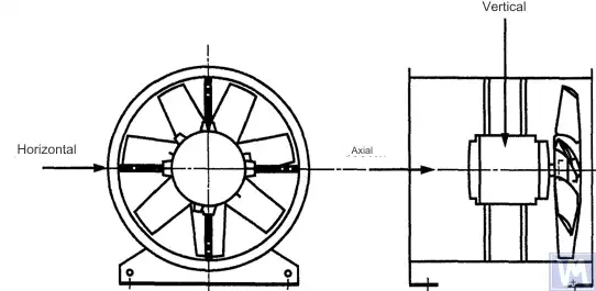
Figure 1. Location of a three-coordinate sensor for a horizontally mounted axial fan
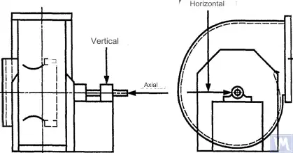
Figure 2. Location of a three-coordinate sensor for a single-suction radial fan
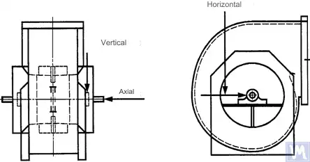
Figure 3. Location of a three-coordinate sensor for a double-suction radial fan
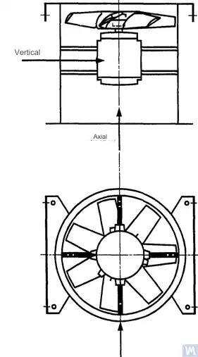
Figure 4. Location of a three-coordinate sensor for a vertically mounted axial fan
Measurements in the horizontal direction should be carried out at a right angle to the shaft axis. Measurements in the vertical direction should be carried out at a right angle to the horizontal measurement direction and perpendicular to the fan shaft. Measurements in the longitudinal direction should be carried out parallel to the shaft axis.
Measurements using inertia-type sensors
All vibration values specified in this standard refer to measurements taken using inertia-type sensors, the signal of which reproduces the movement of the bearing housing.
The sensors used can be either accelerometers or velocity sensors. Particular attention should be paid to the correct attachment of sensors: without gaps on the support surface, without swings and resonances. The size and mass of the sensors and the attachment system should not be excessively large to avoid significant changes in the measured vibration. The total error caused by the method of sensor attachment and calibration of the measuring system should not exceed +/- 10% of the measured value.
Measurements using non-contact sensors
By agreement between the user and the manufacturer, requirements for the maximum allowable shaft displacement (see ISO 7919-1) within sliding bearings may be established. The corresponding measurements can be carried out using non-contact sensors.
In this case, the measuring system determines the displacement of the shaft surface relative to the bearing housing. It is obvious that the allowable amplitude of displacements should not exceed the value of the bearing clearance. The clearance value depends on the size and type of bearing, the load (radial or axial), and the measurement direction (some bearing designs have an elliptical hole, for which the clearance in the horizontal direction is greater than in the vertical direction). The variety of factors that need to be considered does not allow setting uniform shaft displacement limits, but some recommendations are presented in table 3. The values given in this table represent a percentage of the total radial clearance value in the bearing in each direction.
Table 3 – Maximum Relative Shaft Displacement within the Bearing
| Fan Vibrational State | Maximum Recommended Displacement, Percentage of Clearance Value (Along Any Axis) |
| Commissioning/Satisfactory State | Less than 25% |
| Warning | +50% |
| Shutdown | +70% |
| 1) Radial and axial clearance values for a specific bearing should be obtained from its supplier. | |
The given values take into account “false” displacements of the shaft surface. These “false” displacements appear in the measurement results because, in addition to the shaft vibration, mechanical runouts also affect these results if the shaft is bent or has an out-of-round shape. When using a non-contact sensor, the measurement results will also include electrical runouts determined by the magnetic and electrical properties of the shaft material at the measurement point. It is believed that during the commissioning and subsequent normal operation of the fan, the range of the sum of mechanical and electrical runouts at the measurement point should not exceed the larger of two values: 0.0125 mm or 25% of the measured displacement value. Runouts are determined by slowly rotating the shaft (at a speed of 25 to 400 rpm), when the effect of forces caused by imbalance on the rotor is negligible. To meet the established runout tolerance, additional shaft machining may be required. Non-contact sensors should, if possible, be mounted directly on the bearing housing.
The given limit values apply only to a fan operating in its nominal mode. If the fan design allows operation with variable rotational speed, higher vibration levels are possible at other speeds due to the inevitable influence of resonances.
If the fan design allows changing the blade positions relative to the airflow at the intake port, the given values should be applied for conditions with the blades fully open. It should be noted that airflow stall, especially noticeable at large blade angles relative to the intake airflow, can lead to increased vibration levels.
Fan Support System
The vibrational state of fans after installation is determined considering the support stiffness. A support is considered rigid if the first natural frequency of the “fan – support” system exceeds the rotational speed. Usually, when mounted on large concrete foundations, the support can be considered rigid, and when mounted on vibration isolators – compliant. A steel frame, often used for mounting fans, can belong to either of the two support types. In case of doubt about the fan support type, calculations or tests can be carried out to determine the system’s first natural frequency. In some cases, the fan support should be considered rigid in one direction and compliant in another.
Limits of Allowable Fan Vibration during Factory Tests
The limit vibration levels given in table 4 apply to assembled fans. They relate to narrow-band vibration velocity measurements at bearing supports for the rotational frequency used during factory tests.
Jedwali la 4 - Punguza Maadili ya Mtetemo wakati wa Majaribio ya Kiwanda
| Fan Category | Punguza Kasi ya Mtetemo wa RMS, mm/s | |
| Usaidizi Mgumu | Usaidizi Unaokubalika | |
| BV-1 | 9.0 | 11.2 |
| BV-2 | 3.5 | 5.6 |
| BV-3 | 2.8 | 3.5 |
| BV-4 | 1.8 | 2.8 |
| BV-5 | 1.4 | 1.8 |
| Notes
1 Kanuni za kubadilisha vitengo vya kasi ya mtetemo kuwa vitengo vya kuhamisha au kuongeza kasi kwa mtetemo wa bendi nyembamba zimebainishwa katika Kiambatisho A.
2 Thamani katika jedwali hili hutumika kwa mzigo wa kawaida na mzunguko wa kawaida wa feni inayofanya kazi katika hali iliyo na miongozo ya ingizo wazi. Maadili ya kikomo kwa masharti mengine ya upakiaji yanapaswa kukubaliana kati ya mtengenezaji na mteja, lakini inashauriwa kuwa hayazidi maadili ya jedwali kwa zaidi ya mara 1.6.
|
||
Vikomo vya Mtetemo Unaoruhusiwa wa Mashabiki wakati wa Jaribio la Kwenye Tovuti
Mtetemo wa shabiki wowote kwenye tovuti ya uendeshaji inategemea si tu juu ya ubora wake wa kusawazisha. Mambo yanayohusiana na usakinishaji, kama vile wingi na ugumu wa mfumo wa usaidizi, pia yatakuwa na ushawishi. Kwa hivyo, mtengenezaji wa feni hawajibikii kiwango cha mtetemo wa feni kwenye tovuti yake ya uendeshaji isipokuwa ikiwa imebainishwa katika mkataba.
Jedwali la 5 linatoa viwango vya kikomo vinavyopendekezwa (katika vitengo vya kasi ya vibration kwa vibration ya broadband kwenye nyumba za kuzaa) kwa uendeshaji wa kawaida wa feni katika kategoria mbalimbali.
Jedwali la 5 - Punguza Maadili ya Mtetemo kwenye Tovuti ya Uendeshaji
| Fan Vibrational State | Fan Category | Punguza Kasi ya Mtetemo wa RMS, mm/s | |
| Usaidizi Mgumu | Usaidizi Unaokubalika | ||
| Kuagiza | BV-1 | 10 | 11.2 |
| BV-2 | 5.6 | 9.0 | |
| BV-3 | 4.5 | 6.3 | |
| BV-4 | 2.8 | 4.5 | |
| BV-5 | 1.8 | 2.8 | |
| Warning | BV-1 | 10.6 | 14.0 |
| BV-2 | 9.0 | 14.0 | |
| BV-3 | 7.1 | 11.8 | |
| BV-4 | 4.5 | 7.1 | |
| BV-5 | 4.0 | 5.6 | |
| Shutdown | BV-1 | __1) | __1) |
| BV-2 | __1) | __1) | |
| BV-3 | 9.0 | 12.5 | |
| BV-4 | 7.1 | 11.2 | |
| BV-5 | 5.6 | 7.1 | |
| 1) Kiwango cha kuzima kwa mashabiki wa kategoria za BV-1 na BV-2 imeanzishwa kulingana na uchambuzi wa muda mrefu wa matokeo ya kipimo cha vibration. | |||
Mtetemo wa mashabiki wapya wanaoagizwa haupaswi kuzidi kiwango cha "kutuma". Kadiri feni inavyofanya kazi, kiwango chake cha mtetemo kinatarajiwa kuongezeka kwa sababu ya michakato ya uchakavu na athari limbikizo za vishawishi. Ongezeko hilo la vibration kwa ujumla ni la asili na haipaswi kusababisha wasiwasi mpaka kufikia kiwango cha "onyo".
Baada ya kufikia kiwango cha "onyo" cha vibration, ni muhimu kuchunguza sababu za kuongezeka kwa vibration na kuamua hatua za kupunguza. Operesheni ya shabiki katika hali hii inapaswa kuwa chini ya ufuatiliaji wa mara kwa mara na mdogo kwa muda unaohitajika kutambua hatua za kuondoa sababu za kuongezeka kwa vibration.
Ikiwa kiwango cha vibration kinafikia kiwango cha "kuzima", hatua za kuondoa sababu za kuongezeka kwa vibration lazima zichukuliwe mara moja, vinginevyo, shabiki inapaswa kusimamishwa. Kuchelewesha kuleta kiwango cha vibration kwa kiwango kinachokubalika kunaweza kusababisha uharibifu wa kuzaa, nyufa kwenye rotor, na katika sehemu za kulehemu za nyumba ya shabiki, na hatimaye kusababisha uharibifu wa shabiki.
Wakati wa kutathmini hali ya mtetemo wa feni, ni muhimu kufuatilia mabadiliko katika viwango vya mtetemo kwa wakati. Mabadiliko ya ghafla katika kiwango cha mtetemo yanaonyesha hitaji la ukaguzi wa haraka wa shabiki na hatua za matengenezo. Wakati wa kufuatilia mabadiliko ya vibration, taratibu za mpito zinazosababishwa na, kwa mfano, uingizwaji wa lubricant au taratibu za matengenezo hazipaswi kuzingatiwa.
Athari za Utaratibu wa Bunge
Mbali na magurudumu, mashabiki hujumuisha vipengele vingine vinavyozunguka vinavyoweza kuathiri kiwango cha vibration ya shabiki: puli za gari, mikanda, viunganishi, rotor za motor, au vifaa vingine vya kuendesha. Ikiwa masharti ya kuagiza yanahitaji ugavi wa feni bila kifaa cha kuendesha gari, inaweza kuwa vigumu kwa mtengenezaji kufanya majaribio ya mkusanyiko ili kubaini viwango vya mtetemo. Katika hali kama hiyo, hata ikiwa mtengenezaji amesawazisha gurudumu la shabiki, hakuna uhakika kwamba shabiki ataendesha vizuri hadi shimoni la shabiki limeunganishwa kwenye gari na mashine nzima ijaribiwe kwa vibration wakati wa kuwaagiza.
Kawaida, baada ya mkusanyiko, kusawazisha kwa ziada inahitajika ili kupunguza kiwango cha vibration kwa kiwango kinachokubalika. Kwa mashabiki wote wapya wa kategoria BV-3, BV-4, na BV-5, inashauriwa kupima vibration kwa mashine iliyokusanyika kabla ya kuwaagiza. Hii itaweka msingi na kuelezea hatua zaidi za matengenezo.
Wazalishaji wa shabiki hawana jukumu la athari kwenye vibration ya sehemu za gari zilizowekwa baada ya kupima kiwanda.
Zana za Vipimo vya Mtetemo na Urekebishaji
Zana za Kupima
Zana za kupima na mashine za kusawazisha zinazotumiwa lazima zidhibitishwe na kukidhi mahitaji ya kazi. Muda kati ya uthibitishaji unatambuliwa na mapendekezo ya mtengenezaji kwa zana za kupima (mtihani). Hali ya zana za kipimo lazima ihakikishe uendeshaji wao wa kawaida katika kipindi chote cha kupima.
Wafanyakazi wanaofanya kazi na zana za kupima lazima wawe na ujuzi na uzoefu wa kutosha ili kugundua hitilafu zinazoweza kutokea na kuzorota kwa ubora wa zana za vipimo.
Urekebishaji
Zana zote za kipimo lazima zirekebishwe kulingana na viwango. Ugumu wa utaratibu wa urekebishaji unaweza kutofautiana kutoka kwa ukaguzi rahisi wa kimwili hadi urekebishaji wa mfumo mzima. Misa ya kurekebisha inayotumiwa kubainisha usawa wa mabaki kulingana na ISO 1940-1 pia inaweza kutumika kusawazisha zana za vipimo.
Nyaraka
Kusawazisha
Kwa ombi, ikiwa imetolewa na masharti ya mkataba, ripoti ya mtihani wa kusawazisha shabiki inaweza kutolewa kwa mteja, ambayo inashauriwa kujumuisha habari ifuatayo:
- Jina la mtengenezaji wa mashine ya kusawazisha, nambari ya mfano;
- Aina ya usakinishaji wa rotor: kati ya msaada au cantilevered;
- Njia ya kusawazisha: tuli au yenye nguvu;
- Misa ya sehemu zinazozunguka za mkusanyiko wa rotor;
– Kutokuwa na usawa uliobaki katika kila uso wa kusahihisha (use our kikokotoo cha uzani wa sehemu iliyobaki (ISO 21940-11) ili kubainisha thamani zinazoruhusiwa);
- usawa wa mabaki unaoruhusiwa katika kila uso wa kusahihisha;
- darasa la usahihi wa kusawazisha;
- Vigezo vya kukubalika: kukubaliwa / kukataliwa;
- Cheti cha kusawazisha (ikiwa ni lazima).
- Jina la mtengenezaji wa mashine ya kusawazisha, nambari ya mfano;
- Aina ya usakinishaji wa rotor: kati ya msaada au cantilevered;
- Njia ya kusawazisha: tuli au yenye nguvu;
- Misa ya sehemu zinazozunguka za mkusanyiko wa rotor;
– Kutokuwa na usawa uliobaki katika kila uso wa kusahihisha (use our kikokotoo cha uzani wa sehemu iliyobaki (ISO 21940-11) ili kubainisha thamani zinazoruhusiwa);
- usawa wa mabaki unaoruhusiwa katika kila uso wa kusahihisha;
- darasa la usahihi wa kusawazisha;
- Vigezo vya kukubalika: kukubaliwa / kukataliwa;
- Cheti cha kusawazisha (ikiwa ni lazima).
Mtetemo
Kwa ombi, ikiwa imetolewa na masharti ya mkataba, ripoti ya jaribio la mtetemo wa shabiki inaweza kutolewa kwa mteja, ambayo inapendekezwa kujumuisha habari ifuatayo:
- Vifaa vya kupimia vilivyotumika;
- Njia ya kiambatisho cha sensor ya vibration;
Vigezo vya uendeshaji wa feni (mtiririko wa hewa, shinikizo, nguvu);
- mzunguko wa shabiki;
- Aina ya usaidizi: ngumu au inayoambatana;
- Vibration iliyopimwa:
1) Nafasi za sensor ya mtetemo na shoka za kipimo,
2) Vipimo vya kipimo na viwango vya kumbukumbu vya vibration,
3) Kiwango cha mzunguko wa kipimo (bendi nyembamba au pana);
- Viwango vinavyoruhusiwa vya mtetemo;
- Viwango vya mtetemo vilivyopimwa;
- Vigezo vya kukubalika: kukubaliwa / kukataliwa;
- Cheti cha kiwango cha mtetemo (ikiwa ni lazima).
- Vifaa vya kupimia vilivyotumika;
- Njia ya kiambatisho cha sensor ya vibration;
Vigezo vya uendeshaji wa feni (mtiririko wa hewa, shinikizo, nguvu);
- mzunguko wa shabiki;
- Aina ya usaidizi: ngumu au inayoambatana;
- Vibration iliyopimwa:
1) Nafasi za sensor ya mtetemo na shoka za kipimo,
2) Vipimo vya kipimo na viwango vya kumbukumbu vya vibration,
3) Kiwango cha mzunguko wa kipimo (bendi nyembamba au pana);
- Viwango vinavyoruhusiwa vya mtetemo;
- Viwango vya mtetemo vilivyopimwa;
- Vigezo vya kukubalika: kukubaliwa / kukataliwa;
- Cheti cha kiwango cha mtetemo (ikiwa ni lazima).
METHODS OF BALANCING FANS ON A BALANCING MACHINE
B.1. Direct Drive Fan
B.1.1. General Provisions
The fan wheel, which is mounted directly on the motor shaft during assembly, should be balanced according to the same rule for accounting for the keyway effect as for the motor shaft.
Motors from previous years of production could be balanced using a full keyway. Currently, motor shafts are balanced using a half-keyway, as prescribed by ISO 8821 (adopted as GOST 31322), and marked with the letter H (see ISO 8821).
B.1.2. Motors Balanced with a Full Keyway
The fan wheel, mounted on the motor shaft balanced with a full keyway, should be balanced without a key on a tapered arbor.
B.1.3. Motors Balanced with a Half-Keyway
For the fan wheel mounted on the motor shaft balanced with a half-keyway, the following options are possible:
a) if the wheel has a steel hub, cut a keyway in it after balancing;
b) balance on a tapered arbor with a half-key inserted into the keyway;
c) balance on an arbor with one or more keyways (see B.3), using full keys.
a) if the wheel has a steel hub, cut a keyway in it after balancing;
b) balance on a tapered arbor with a half-key inserted into the keyway;
c) balance on an arbor with one or more keyways (see B.3), using full keys.
B.2. Fans Driven by Another Shaft
Where possible, all rotating elements, including the fan shaft and pulley, should be balanced as a single unit. If this is impractical, balancing should be performed on an arbor (see B.3) using the same keyway accounting rule as for the shaft.
B.3. Arbor
The arbor on which the fan wheel is mounted during balancing must meet the following requirements:
a) be as light as possible;
b) be in a balanced state, ensured by appropriate maintenance and regular inspections;
c) preferably be tapered to reduce errors associated with eccentricity, resulting from the tolerances of the hub hole and arbor dimensions. If the arbor is tapered, the true position of the correction planes relative to the bearings should be considered in the imbalance calculations.
a) be as light as possible;
b) be in a balanced state, ensured by appropriate maintenance and regular inspections;
c) preferably be tapered to reduce errors associated with eccentricity, resulting from the tolerances of the hub hole and arbor dimensions. If the arbor is tapered, the true position of the correction planes relative to the bearings should be considered in the imbalance calculations.
If it is necessary to use a cylindrical arbor, it should have a keyway cut into it, into which a full key is inserted to transmit the torque from the arbor to the fan wheel.
Another option is to cut two keyways on opposite ends of the shaft diameter, allowing the use of the reverse balancing method. This method involves the following steps. First, measure the wheel imbalance by inserting a full key into one keyway and a half-key into the other. Then rotate the wheel 180° relative to the arbor and measure its imbalance again. The difference between the two imbalance values is due to the residual imbalance of the arbor and the universal drive joint. To obtain the true rotor imbalance value, take half the difference of these two measurements.
SOURCES OF FAN VIBRATION
There are many sources of vibration within the fan, and vibration at certain frequencies can be directly linked to specific design features of the machine. This appendix only covers the most common vibration sources observed in most types of fans. The general rule is that any looseness in the support system causes deterioration in the fan’s vibrational state.
Fan Imbalance
Hii ndiyo chanzo kikuu cha mtetemo wa feni; inajulikana na uwepo wa kipengele cha mtetemo katika masafa ya mzunguko (harmonic ya kwanza harmonic). Sababu ya kutokuwa na usawa ni kwamba mhimili wa uzito unaozunguka uko nje ya katikati au umepinda dhidi ya mhimili wa mzunguko. Hii inaweza kusababishwa na mgawanyo usio sawa wa uzito, jumla ya uvumilivu wa vipimo vya tundu la kiota cha mhimili, ukunju wa mhimili, au mchanganyiko wa mambo haya. Mtetemo unaosababishwa na kutokuwa na usawa huathiri hasa mwelekeo wa radial.
Temporary shaft bending can result from uneven mechanical heating – due to friction between rotating and stationary elements – or electrical nature. Permanent bending can result from changes in material properties or misalignment of the shaft and fan wheel when the fan and motor are separately mounted.
During operation, the fan wheel imbalance can increase due to particle deposition from the air. When operating in an aggressive environment, imbalance can result from uneven erosion or corrosion of the wheel.
Imbalance can be corrected by additional balancing in the appropriate planes, but before performing the balancing procedure, the sources of imbalance should be identified, eliminated, and the machine’s vibrational stability checked.
Fan and Motor Misalignment
This defect can occur when the motor and fan shafts are connected via a belt drive or flexible coupling. Misalignment can sometimes be identified by characteristic vibration frequency components, usually the first and second harmonics of the rotational frequency. In the case of parallel misalignment of the shafts, vibration primarily occurs in the radial direction, while if the shafts intersect at an angle, longitudinal vibration may become dominant.
If the shafts are connected at an angle and rigid couplings are used, alternating forces begin to act in the machine, causing increased wear of the shafts and couplings. This effect can be significantly reduced by using flexible couplings.
Fan Vibration Due to Aerodynamic Excitation
Uchochezi wa mtetemo unaweza kusababishwa na mwingiliano wa gurudumu la feni na vipengele visivyosogea vya muundo, kama vile vane za mwongozo, injini, au vitegemezi vya beari, thamani zisizo sahihi za pengo, au miundo ya ulaji na utokaji wa hewa iliyoundwa vibaya. Kipengele cha kipekee cha vyanzo hivi ni kutokea kwa mtetemo wa mara kwa mara unaohusiana na masafa ya mzunguko wa gurudumu, dhidi ya msingi wa mabadiliko ya nasibu katika mwingiliano wa mapale ya gurudumu na hewa. Mtetemo unaweza kuonekana katika harmonic za masafa ya mapale, ambayo ni zao la masafa ya mzunguko wa gurudumu na idadi ya mapale ya gurudumu.
Aerodynamic instability of the airflow, caused by its stall from the blade surface and subsequent vortex formation, causes broadband vibration, the spectrum shape of which changes depending on the fan’s load.
Aerodynamic noise is characterized by the fact that it is not related to the wheel’s rotational frequency and can occur at subharmonics of the rotational frequency (i.e., at frequencies below the rotational frequency). In this case, significant vibration of the fan housing and ducts can be observed.
If the aerodynamic system of the fan is poorly matched with its characteristics, sharp impacts may occur in it. These impacts are easily distinguishable by ear and are transmitted as impulses to the fan support system.
If the above-mentioned causes lead to blade vibration, its nature can be investigated by installing sensors in different parts of the structure.
Fan Vibration Due to Whirl in the Oil Layer
Whirls that may occur in the lubrication layer of sliding bearings are observed at a characteristic frequency slightly below the rotor’s rotational frequency unless the fan operates at a speed exceeding the first critical. In the latter case, oil wedge instability will be observed at the first critical speed, and sometimes this effect is called resonant whirl.
Sources of Electrical Nature Fan Vibration
Uneven heating of the motor rotor can cause it to bend, leading to imbalance (manifesting at the first harmonic).
In the case of an asynchronous motor, the presence of a component at a frequency equal to the rotational frequency multiplied by the number of rotor plates indicates defects related to the stator plates, and vice versa, components at a frequency equal to the rotational frequency multiplied by the number of rotor plates indicate defects related to the rotor plates.
Many vibration components of electrical nature are characterized by their immediate disappearance when the power supply is turned off.
Fan Vibration Due to Belt Drive Excitation
Generally, there are two types of problems related to belt drives: when the drive’s operation is influenced by external defects and when the defects are in the belt itself.
In the first case, although the belt vibrates, this is due to forcing forces from other sources, so replacing the belt will not produce the desired results. Common sources of such forces are imbalance in the drive system, pulley eccentricity, misalignment, and loosened mechanical connections. Therefore, before changing the belts, vibration analysis should be carried out to identify the excitation source.
If the belts respond to external forcing forces, their vibration frequency will most likely be the same as the excitation frequency. In this case, the excitation frequency can be determined using a stroboscopic lamp, adjusting it so that the belt appears stationary in the lamp’s light.
In the case of a multi-belt drive, unequal belt tension can lead to a significant increase in the transmitted vibration.
Cases where the vibration sources are the belts themselves are related to their physical defects: cracks, hard and soft spots, dirt on the belt surface, missing material from its surface, etc. For V-belts, changes in their width will cause the belt to ride up and down the pulley track, creating vibration due to changing its tension.
If the vibration source is the belt itself, the vibration frequencies are usually the harmonics of the belt’s rotational frequency. In a specific case, the excitation frequency will depend on the nature of the defect and the number of pulleys, including tensioners.
In some cases, the vibration amplitude may be unstable. This is especially true for multi-belt drives.
Mechanical and electrical defects are sources of vibration, which subsequently convert into airborne noise. Mechanical noise can be associated with fan or motor imbalance, bearing noise, axis alignment, duct wall and housing panel vibrations, damper blade vibrations, blade, damper, pipe, and support vibrations, as well as transmission of mechanical vibrations through the structure. Electrical noise is related to various forms of electrical energy conversion: 1) Magnetic forces are determined by the magnetic flux density, the number and shape of the poles, and the geometry of the air gap; 2) Random electrical noise is determined by brushes, arcing, electrical sparks, etc.
Aerodynamic noise can be associated with vortex formation, pressure pulsations, air resistance, etc., and can have both broadband and narrowband nature. Broadband noise can be caused by: a) blades, dampers, and other obstacles in the airflow path; b) fan rotation as a whole, belts, slits, etc.; c) sudden changes in airflow direction or duct cross-section, differences in flow velocities, flow separation due to boundary effects, flow compression effects, etc. Narrowband noise can be caused by: a) resonances (organ pipe effect, string vibrations, panel, structural element vibrations, etc.); b) vortex formation on sharp edges (air column excitation); c) rotations (siren effect, slits, holes, slots on rotating parts).
Impacts created by contact between various mechanical elements of the structure produce noise similar to that produced by a hammer blow, thunder roll, resonating empty box, etc. Impact sounds can be heard from gear teeth impacts and defective belt claps. Impact impulses can be so fleeting that to distinguish periodic impact impulses from transient processes, special high-speed recording equipment is needed. The area where many impact impulses occur, the superimposition of their peaks creates a constant hum effect.
Dependence of Vibration on Fan Support Type
The correct choice of fan support or foundation design is necessary for its smooth, trouble-free operation. To ensure the alignment of rotating components when installing the fan, motor, and other drive devices, a steel frame or reinforced concrete base is used. Sometimes an attempt to save on support construction leads to the inability to maintain the required alignment of the machine components. This is especially unacceptable when vibration is sensitive to alignment changes, particularly for machines consisting of separate parts connected by metal fasteners.
The foundation on which the base is laid can also influence the fan and motor vibration. If the foundation’s natural frequency is close to the fan or motor’s rotational frequency, the foundation will resonate during fan operation. This can be detected by measuring vibration at several points across the foundation, surrounding floor, and fan supports. Often in resonance conditions, the vertical vibration component significantly exceeds the horizontal one. Vibration can be dampened by making the foundation stiffer or increasing its mass. Even if imbalance and misalignment are eliminated, allowing to reduce forcing forces, significant vibration preconditions may still exist. This means that if the fan, together with its support, is close to resonance, achieving acceptable vibration values will require more precise balancing and more accurate shaft alignment than typically required for such machines. This situation is undesirable and should be avoided by increasing the support or concrete block’s mass and/or stiffness.
Vibration Condition Monitoring and Diagnostics Guide
The main principle of machine vibration condition monitoring (hereinafter referred to as the condition) is to observe the results of properly planned measurements to identify a trend of increasing vibration levels and consider it from the perspective of potential problems. Monitoring is applicable in situations where damage develops slowly, and the mechanism’s condition deterioration manifests through measurable physical signs.
Fan vibration, resulting from the development of physical defects, can be monitored at certain intervals, and when an increase in vibration level is detected, the observation frequency can be increased, and a detailed condition analysis can be conducted. In this case, the causes of vibration changes can be identified based on vibration frequency analysis, which allows determining the necessary measures and planning their implementation long before the damage becomes severe. Usually, measures are considered necessary when the vibration level increases by 1.6 times or by 4 dB compared to the baseline level.
The condition monitoring program consists of several stages, which can be briefly formulated as follows:
- a) identify the fan’s condition and determine the baseline vibration level (it may differ from the level obtained during factory tests due to different installation methods, etc.);
- b) select vibration measurement points;
- c) determine the observation (measurement) frequency;
- d) establish the information registration procedure;
- e) determine the criteria for assessing the fan’s vibrational state, limit values for absolute vibration and vibration changes, summarize the experience of operating similar machines.
Since fans typically operate without any problems at speeds not approaching the critical, the vibration level should not significantly change with slight speed or load changes, but it is important to note that when the fan operates with variable rotational speed, the established vibration limit values apply to the maximum operating rotational speed. If the maximum rotational speed cannot be reached within the established vibration limit, this may indicate the presence of a serious problem and require a special investigation.
Some diagnostic recommendations provided in Appendix C are based on fan operation experience and are intended for sequential application when analyzing the causes of increased vibration.
To qualitatively assess the vibration of a specific fan and determine guidelines for further actions, the vibration condition zone boundaries established by ISO 10816-1 can be used.
It is expected that for new fans, their vibration levels will be below the limit values given in table 3. These values correspond to the boundary of zone A of the vibration condition according to ISO 10816-1. Recommended values for warning and shutdown levels are established based on the analysis of information collected on specific types of fans.
COMPLIANCE INFORMATION
REFERENCE INTERNATIONAL STANDARDS USED AS NORMATIVE REFERENCES IN THIS STANDARD
Table H.1
|
Designation of the Reference Interstate Standard
|
Designation and Title of the Reference International Standard and the Conditional Designation of Its Degree of Compliance with the Reference Interstate Standard
|
|
GOST ISO 1940-1-2007
|
ISO 1940-1:1986. Vibration. Requirements for the Balancing Quality of Rigid Rotors. Part 1. Determination of Allowable Imbalance (IDT)
|
|
GOST ISO 5348-2002
|
ISO 5348:1999. Vibration and Shock. Mechanical Mounting of Accelerometers (IDT)
|
|
GOST ISO 7919-1-2002
|
ISO 7919-1:1996. Vibration of Non-Reciprocating Machines. Measurements on Rotating Shafts and Criteria for Evaluation. Part 1. General Guidelines (IDT)
|
|
GOST ISO 10816-1-97
|
ISO 10816-1:1995. Vibration. Evaluation of Machine Condition by Vibration Measurements on Non-Rotating Parts. Part 1. General Guidelines (IDT)
|
|
GOST ISO 10816-3-2002
|
ISO 10816-3:1998. Vibration. Evaluation of Machine Condition by Vibration Measurements on Non-Rotating Parts. Part 3. Industrial Machines with a Nominal Power of More Than 15 kW and Nominal Speeds of 120 to 15000 rpm, in-Situ Measurements (IDT)
|
|
GOST 10921-90
|
ISO 5801:1997. Industrial Fans. Performance Testing Using Standardized Ducts (NEQ)
|
|
GOST 19534-74
|
ISO 1925:2001. Vibration. Balancing. Vocabulary (NEQ)
|
|
GOST 24346-80
|
ISO 2041:1990. Vibration and Shock. Vocabulary (NEQ)
|
|
GOST 31322-2006 (ISO 8821:1989)
|
ISO 8821:1989. Vibration. Balancing. Guidelines for Accounting for the Keyway Effect When Balancing Shafts and Fitted Parts (MOD)
|
|
GOST 31351-2007 (ISO 14695:2003)
|
ISO 14695:2003. Industrial Fans. Vibration Measurement Methods (MOD)
|
|
Note: The following conditional designations of the standard’s compliance degree are used in this table: IDT – identical standards;
|
|


0 Comments