روٹر توازن: جامد اور متحرک عدم توازن، گونج، اور عملی طریقہ کار
یہ گائیڈ روٹر کے توازن کی وضاحت کرتا ہے۔ سخت روٹرز: "غیر توازن" کا کیا مطلب ہے، جامد اور متحرک عدم توازن کس طرح مختلف ہے، کیوں گونج اور غیر لکیری معیار کے نتیجے کو روک سکتے ہیں، اور توازن عام طور پر ایک یا دو اصلاحی طیاروں میں کیسے انجام دیا جاتا ہے۔.


مشمولات
- روٹر کیا ہے اور توازن کیا درست کرتا ہے؟
- روٹرز کی اقسام اور عدم توازن کی اقسام
- میکانزم کی کمپن: کیا توازن ختم کر سکتا ہے اور کیا نہیں ہٹا سکتا
- گونج: ایک ایسا عنصر جو توازن کو روکتا ہے۔
- لکیری بمقابلہ نان لائنر ماڈل: جب حساب کام کرنا چھوڑ دیتا ہے۔
- Balancing devices and balancing machines
- سخت روٹرز کو متوازن کرنا (عملی نوٹ)
- متحرک توازن کیسے انجام دیا جاتا ہے (تھری رن طریقہ)
- توازن کے معیار کا اندازہ لگانے کے لیے معیار
- معیارات اور حوالہ جات
- FAQ
روٹر کیا ہے اور توازن کیا درست کرتا ہے؟
The rotor is a body which rotates about some axis and is held by its bearing surfaces in the supports. The bearing surfaces of the rotor transmit loads to the supports via rolling or sliding bearings. The bearing surfaces are the surfaces of the trunnions or the surfaces that replace them.
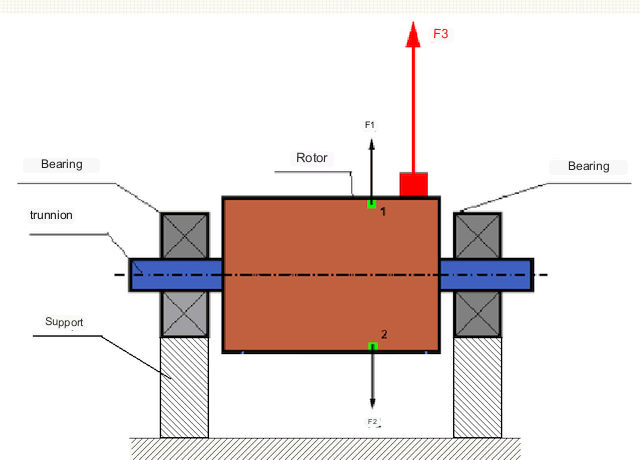
بالکل متوازن روٹر میں، اس کا کمیت گردش کے محور کے بارے میں ہم آہنگی سے تقسیم کیا جاتا ہے، یعنی، روٹر کے کسی بھی عنصر کو گردش کے محور کے بارے میں متوازی طور پر واقع کسی دوسرے عنصر سے ملایا جا سکتا ہے۔ ایک متوازن روٹر میں، کسی بھی روٹر عنصر پر کام کرنے والی سینٹرفیوگل قوت کو سنٹری فیوگل قوت سے متوازن کیا جاتا ہے جو سڈول عنصر پر کام کرتی ہے۔ مثال کے طور پر، سینٹرفیوگل قوتیں F1 اور F2، جس کی شدت میں برابر اور سمت میں مخالف، عناصر 1 اور 2 (تصویر 1 میں سبز نشان زد) پر عمل کرتے ہیں۔ یہ تمام ہموار روٹر عناصر کے لیے درست ہے، اور اس طرح روٹر پر کام کرنے والی کل سینٹرفیوگل قوت 0 ہے اور روٹر متوازن ہے۔.
لیکن اگر روٹر کی ہم آہنگی ٹوٹ جائے (تصویر 1 پر غیر متناسب عنصر کو سرخ رنگ سے نشان زد کیا گیا ہے)، تو غیر متوازن سینٹرفیوگل فورس F3 روٹر پر کام کرتی ہے۔ گھومنے پر، یہ قوت روٹر کی گردش کے ساتھ سمت بدلتی ہے۔ اس قوت کے نتیجے میں متحرک بوجھ بیرنگ میں منتقل ہوتا ہے، جس کے نتیجے میں ٹوٹ پھوٹ کا عمل تیز ہوتا ہے۔.
In addition, under the influence of this variable in direction force there is a cyclic deformation of supports and foundation, on which the rotor is fixed, i.e. there is vibration. In order to eliminate rotor imbalance and the accompanying vibration, balancing masses must be installed to restore symmetry to the rotor.
Rotor balancing is an operation to correct imbalance by adding balancing masses.
The task of balancing is to find the size and location (angle) of one or more balancing masses.
روٹرز کی اقسام اور عدم توازن کی اقسام
روٹر کے مواد کی طاقت اور اس پر کام کرنے والی سینٹری فیوگل قوتوں کی شدت کو مدنظر رکھتے ہوئے، روٹرز کو دو قسموں میں تقسیم کیا جا سکتا ہے - سخت روٹرز اور لچکدار۔.
Rigid rotors deform insignificantly under action of centrifugal force at working modes and influence of this deformation in calculations can be neglected.
لچکدار روٹرز کی اخترتی کو مزید نظرانداز نہیں کیا جاسکتا۔ لچکدار روٹرز کی خرابی توازن کے مسئلے کے حل کو پیچیدہ بناتی ہے اور اسے سخت روٹرز کے توازن کے مسئلے کے مقابلے میں دوسرے ریاضیاتی ماڈلز کے استعمال کی ضرورت ہوتی ہے۔ یہ واضح رہے کہ کم رفتار پر ایک ہی روٹر سخت اور تیز رفتاری پر - جتنا لچکدار ہو سکتا ہے۔ مندرجہ ذیل میں، ہم صرف سخت روٹرز کے توازن پر غور کریں گے۔.
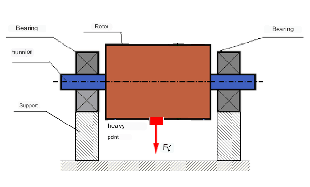
روٹر کی لمبائی کے ساتھ غیر متوازن عوام کی تقسیم پر منحصر ہے، دو قسم کے عدم توازن کو الگ کیا جا سکتا ہے - جامد اور متحرک (لمبی)۔ اس کے مطابق، جامد اور متحرک روٹر توازن کا حوالہ دیا جاتا ہے. جامد روٹر کا عدم توازن روٹر کی گردش کے بغیر ہوتا ہے، یعنی سٹیٹکس میں، جب روٹر اپنے "ہیوی پوائنٹ" کے ساتھ نیچے کی طرف کشش ثقل سے الٹ جاتا ہے۔ جامد عدم توازن کے ساتھ روٹر کی ایک مثال تصویر 2 میں دکھائی گئی ہے۔
Dynamic unbalance occurs only when the rotor is rotating.
An example of a rotor with dynamic unbalance is shown in Fig. 3.
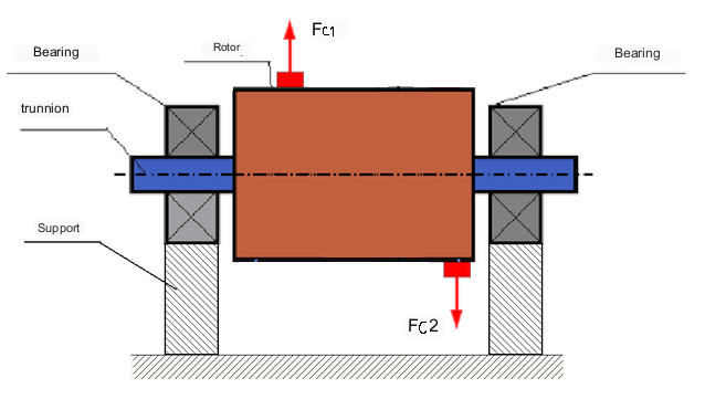
اس صورت میں، غیر متوازن مساوی ماس M1 اور M2 مختلف طیاروں میں ہیں - روٹر کی لمبائی کے ساتھ مختلف جگہوں پر۔ جامد پوزیشن میں، یعنی جب روٹر نہیں گھومتا ہے، صرف کشش ثقل روٹر پر کام کرتی ہے اور ماس ایک دوسرے کو متوازن کرتے ہیں۔ حرکیات میں، جب روٹر گھومتا ہے، سینٹرفیوگل قوتیں Fc1 اور Fc2 عوام M1 اور M2 پر کام کرنا شروع کر دیتی ہیں۔ یہ قوتیں شدت میں برابر اور سمت میں مخالف ہیں۔ تاہم، چونکہ وہ شافٹ کی لمبائی کے ساتھ مختلف جگہوں پر لاگو ہوتے ہیں اور ایک ہی لائن پر نہیں ہوتے ہیں، یہ قوتیں ایک دوسرے کی تلافی نہیں کرتی ہیں۔ فورسز Fc1 اور Fc2 روٹر پر لاگو ٹارک بناتے ہیں۔ اس لیے اس عدم توازن کو لمحہ عدم توازن بھی کہا جاتا ہے۔ اس کے مطابق، غیر معاوضہ سینٹرفیوگل قوتیں بیئرنگ پوزیشنز پر کام کرتی ہیں، جو کہ حسابی قدروں سے بہت زیادہ بڑھ سکتی ہیں اور بیرنگ کی سروس لائف کو کم کر سکتی ہیں۔.
چونکہ اس قسم کا عدم توازن صرف روٹر کی گردش کے دوران متحرک طور پر ہوتا ہے، اس لیے اسے متحرک عدم توازن کہا جاتا ہے۔ اسے جامد حالات میں "چھریوں پر" یا اسی طرح کے طریقوں سے درست نہیں کیا جا سکتا۔ متحرک عدم توازن کو ختم کرنے کے لیے، دو معاوضہ دینے والے وزن نصب کیے جائیں، جو کہ ایک لمحہ کی شدت میں مساوی اور مخالف سمت میں ماس M1 اور M2 سے پیدا ہونے والے لمحے پیدا کرتے ہیں۔ معاوضہ دینے والے ماسز کو M1 اور M2 کی شدت میں مخالف اور مساوی سیٹ کرنے کی ضرورت نہیں ہے۔ اہم بات یہ ہے کہ وہ ایک ایسا لمحہ پیدا کرتے ہیں جو عدم توازن کے لمحے کی مکمل تلافی کرتا ہے۔.
عام طور پر، بڑے پیمانے پر M1 اور M2 ایک دوسرے کے برابر نہیں ہوسکتے ہیں، لہذا جامد اور متحرک عدم توازن کا مجموعہ ہوگا۔ یہ نظریاتی طور پر ثابت ہے کہ ایک سخت روٹر کے لیے، روٹر کی لمبائی کے ساتھ الگ الگ دو وزن ضروری اور اس کے عدم توازن کو ختم کرنے کے لیے کافی ہیں۔ یہ وزن متحرک عدم توازن کے نتیجے میں پیدا ہونے والے ٹارک اور روٹر محور (جامد عدم توازن) کے نسبت بڑے پیمانے پر عدم توازن کے نتیجے میں بننے والی سینٹرفیوگل قوت دونوں کی تلافی کریں گے۔ عام طور پر، متحرک عدم توازن طویل روٹرز کی خصوصیت ہے، جیسے شافٹ، اور جامد عدم توازن تنگ روٹرز کی خصوصیت ہے۔ تاہم، اگر تنگ روٹر محور کی نسبت ترچھا ہوا ہے، یا بگڑا ہوا ہے ("شکل آٹھ")، تو متحرک عدم توازن کو ختم کرنا مشکل ہوگا۔ (تصویر 4 دیکھیں)، کیونکہ اس صورت میں درست کرنے والے وزن کو انسٹال کرنا مشکل ہے جو ضروری معاوضہ کا لمحہ پیدا کرتے ہیں۔.
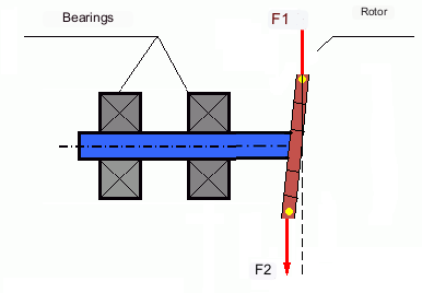
The forces F1 and F2 do not lie on the same line and do not compensate each other.
اس حقیقت کی وجہ سے کہ ٹارک بنانے کے لیے بازو تنگ روٹر کی وجہ سے چھوٹا ہے، بڑے درست وزن کی ضرورت پڑ سکتی ہے۔ تاہم، اصلاحی وزن سے سینٹرفیوگل قوتوں کے ذریعے تنگ روٹر کی خرابی کی وجہ سے اس کا نتیجہ "حوصلہ افزائی عدم توازن" میں بھی ہوتا ہے۔ (مثال کے طور پر "سخت روٹرز (ISO 22061-76 پر) توازن کے لیے طریقہ کار کی ہدایات دیکھیں۔" سیکشن 10۔ روٹر سپورٹ سسٹم۔)
This is noticeable for narrow impellers of fans, in which, in addition to force unbalance, aerodynamic unbalance is also active. And it should be understood that aerodynamic unbalance, or rather aerodynamic force is directly proportional to angular speed of the rotor, and for its compensation the centrifugal force of correcting mass, which is proportional to the square of angular speed, is used. Therefore, the balancing effect can only take place at a specific balancing frequency. At other rotational frequencies there is an additional error.
The same can be said of the electromagnetic forces in an electric motor, which are also proportional to angular velocity. So it is not possible to eliminate all causes of vibration in a machine by balancing.
میکانزم کی کمپن
Vibration is the reaction of the mechanism design to the effects of a cyclic excitatory force. This force can be of different nature.
غیر متوازن روٹر کے نتیجے میں سینٹرفیوگل فورس ایک غیر معاوضہ قوت ہے جو "بھاری نقطہ" پر کام کرتی ہے۔ یہ قوت اور اس کی وجہ سے ہونے والی کمپن ہے جسے روٹر کو متوازن کرکے ختم کیا جاسکتا ہے۔.
میٹنگ حصوں کی تیاری اور اسمبلی کی غلطیوں سے پیدا ہونے والی "جیومیٹریکل" نوعیت کی باہمی تعامل قوتیں۔ یہ قوتیں، مثال کے طور پر، شافٹ کی گردن کے غیر گول ہونے، گیئرز میں دانتوں کے پروفائلز میں خرابی، بیئرنگ ریس ویز کی لہر، میٹنگ شافٹ کی غلط ترتیب وغیرہ کے نتیجے میں پیدا ہو سکتی ہیں۔ جرنلز کی غیر گولائی کی صورت میں شافٹ کا محور شافٹ کی روٹ کے لحاظ سے بے گھر ہو جائے گا۔ اگرچہ یہ وائبریشن روٹر کی رفتار سے بھی ہوتی ہے، لیکن توازن کے ذریعے اسے ختم کرنا تقریباً ناممکن ہے۔.
Aerodynamic forces resulting from the rotation of the impellers of fans and other vane mechanisms. Hydrodynamic forces resulting from the rotation of impellers of hydraulic pumps, turbines, etc.
Electromagnetic forces resulting from the operation of electrical machines, e.g. asymmetric rotor windings, short-circuited windings, etc.
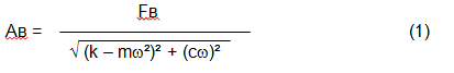
The magnitude of the vibration (e.g. its amplitude Av) depends not only on the excitatory force Fv acting on the mechanism with circular frequency ω, but also on the rigidity k of the mechanism, its mass m , as well as the damping coefficient C.
Various types of sensors can be used to measure vibration and balance mechanisms, including:
- absolute vibration sensors designed to measure vibration acceleration (accelerometers) and vibration velocity sensors;
- متعلقہ وائبریشن کے سینسر - ایڈی کرنٹ یا کیپسیٹیو، کمپن کی نقل مکانی کی پیمائش کرنے کے لیے ڈیزائن کیا گیا ہے۔;
- کچھ معاملات میں (جب میکانزم کا ڈیزائن اس کی اجازت دیتا ہے)، اس کے کمپن بوجھ کا اندازہ کرنے کے لیے فورس سینسر بھی استعمال کیے جا سکتے ہیں۔ خاص طور پر، وہ بڑے پیمانے پر ہارڈ بیئرنگ بیلنسنگ مشین سپورٹ کے کمپن بوجھ کی پیمائش کے لیے استعمال ہوتے ہیں۔.
So, vibration is the reaction of a machine to the action of external forces. The magnitude of vibration depends not only on the magnitude of the force acting on the mechanism, but also on the rigidity of the mechanism design. One and the same force can lead to different vibrations. In a hard-bearing machine, even if the vibration is small, the bearings may be subjected to significant dynamic loads. This is why force rather than vibration sensors (vibration accelerometers) are used when balancing hard-bearing machines.
Vibration sensors are used on mechanisms with relatively pliable supports, when the action of unbalanced centrifugal forces leads to a noticeable deformation of supports and vibration. Force sensors are used for rigid supports, when even significant forces due to unbalance do not lead to significant vibration.
Resonance is a factor that prevents balancing
Earlier we mentioned that rotors are divided into rigid and flexible. Stiffness or flexibility of rotor should not be confused with stiffness or mobility of supports (foundation) on which the rotor is installed. A rotor is considered rigid when its deformation (bending) under the action of centrifugal forces can be neglected. Deformation of flexible rotor is relatively large and cannot be neglected.
In this article, we consider only the balancing of rigid rotors. A rigid (non-deformable) rotor can in turn be mounted on rigid or movable (pliable) supports. It is clear that this stiffness/suspendability of supports is also relative, depending on rotor speed and magnitude of resulting centrifugal forces. A conditional boundary is the frequency of natural vibrations of the rotor supports.
For mechanical systems, the shape and frequency of natural vibrations are determined by the mass and the elasticity of the elements of mechanical system. That is, the frequency of natural vibrations is an internal characteristic of the mechanical system and does not depend on external forces. Being deflected from the state of equilibrium, supports due to elasticity tend to return to the position of equilibrium. But due to the inertia of the massive rotor, this process is in the nature of damped oscillations. These vibrations are the natural vibrations of the rotor-support system. Their frequency depends on the ratio of the mass of the rotor to the elasticity of the supports.
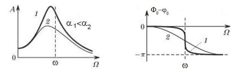
When the rotor begins to rotate and the frequency of its rotation approaches the frequency of natural vibrations, the amplitude of vibration increases sharply, which can lead to the destruction of the structure.
The phenomenon of mechanical resonance occurs. In the area of resonance, a change of rotation speed by 100 rpm may lead to an increase in vibration by tens of times. At the same time (in the resonance area) the vibration phase changes by 180°.
If the design of the mechanism is unsuccessful and the operating frequency of the rotor is close to the frequency of natural vibrations, then the operation of the mechanism becomes impossible because of the inadmissibly high vibration. This is not possible in the usual way, since even a small change in speed will cause a drastic change in the vibration parameters. For balancing in the area of resonance, special methods not considered in this article are used.
It is possible to determine the frequency of natural vibrations of the mechanism at coasting (at switching off the rotor rotation) or by the shock method with the subsequent spectral analysis of the system response to the shock.
For mechanisms, which working frequency of rotation is above the resonance frequency, i.e. working in the resonance regime, the supports are considered to be moving and for measurement are used vibration sensors, mainly vibroacelerometers, measuring acceleration of structural elements. For mechanisms operating in preresonant mode, the supports are considered rigid. In this case, force sensors are used.
Linear and nonlinear models of a mechanical system. Non-linearity is a factor that prevents balancing
When balancing rigid rotors, mathematical models called linear models are used for balancing calculations. A linear model means that in such a model, one quantity is proportional (linear) to the other. For example, if the uncompensated mass on the rotor is doubled, then the vibration value will also be doubled. For rigid rotors, a linear model can be used, since they do not deform.
For flexible rotors, the linear model can no longer be used. For a flexible rotor, if the mass of the heavy point increases during rotation, additional deformation will occur, and in addition to the mass, the radius of the location of the heavy point will also increase. Therefore, for a flexible rotor, the vibration will increase more than twofold, and the usual methods of calculation will not work.
Also, the change of elasticity of supports at their large deformations, for example, when at small deformations of supports some structural elements work, and at large ones other structural elements are involved. This is why you cannot balance mechanisms that are not fixed on a foundation, but, for example, simply placed on the floor. With significant vibrations, the force of the imbalance can pull the mechanism off the floor, thereby significantly changing the stiffness characteristics of the system. Motor feet must be securely fastened, bolt mounts must be tightened, washer thickness must provide sufficient mounting rigidity, etc. If the bearings are broken, significant shaft misalignment and shocks are possible, which will also result in poor linearity and an inability to perform a quality balance.
Balancing devices and balancing machines
جیسا کہ اوپر بتایا گیا ہے، توازن جڑتا کے مرکزی مرکزی محور کو روٹر کے گردش کے محور کے ساتھ سیدھ میں کرنے کا عمل ہے۔.
This process can be performed by two methods.
The first method involves machining the rotor trunnions in such a way that the axis passing through the centers of the trunnions cross section with the main central axis of inertia of the rotor. Such a technique is rarely used in practice and will not be discussed in detail in this article.
The second (most common) method involves moving, installing or removing correction weights on the rotor, which are placed so that the axis of inertia of the rotor is as close to its axis of rotation as possible.
Moving, adding or removing correction weights during balancing may be accomplished by various technological operations including: drilling, milling, surfacing, welding, screwing or unscrewing, laser or electron beam burning, electrolysis, electromagnetic surfacing, etc.
The balancing process can be accomplished in two ways:
- balancing of assembled rotors (in their own bearings) using balancing machines;
- balancing of rotors on balancing machines. For balancing of rotors in their own bearings usually used specialized balancing devices (kits), which allow to measure the vibration of the balanced rotor at its frequency of rotation in vector form, i.e. to measure both the amplitude and the phase of vibration. At present, the above devices are manufactured on the basis of microprocessor technology and (apart from vibration measurement and analysis) provide automatic calculation of parameters of correcting weights, which should be installed on the rotor to compensate its unbalance.
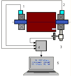
These devices include:
- a measuring and computing unit based on a computer or industrial controller;
- Two (or more) vibration sensors;
- A phase angle sensor;
- accessories for mounting the sensors on the site;
- specialized software, designed to perform a full cycle of rotor vibration parameters measurement in one, two or more correction planes.
Two types of balancing machines are currently the most common:
- Soft-bearings machines (with soft supports);
- Hard-bearings machines (with rigid supports).
نرم بیرنگ مشینوں میں نسبتاً لچکدار سپورٹ ہوتی ہے، مثال کے طور پر، فلیٹ اسپرنگس پر مبنی۔ ان سپورٹوں کے قدرتی کمپن کی فریکوئنسی عام طور پر بیلنسنگ روٹر کی گردش کی فریکوئنسی سے 2-3 گنا کم ہوتی ہے، جو ان پر نصب ہے۔ وائبریشن سینسرز (ایکسلرومیٹر، وائبریشن ویلوسٹی سینسرز، وغیرہ) عام طور پر اس وقت استعمال کیے جاتے ہیں جب مشین کے پریزوننٹ سپورٹ کی کمپن کی پیمائش کی جاتی ہے۔.
Pre-resonance balancing machines use relatively rigid supports, whose natural frequencies of vibration should be 2-3 times higher than the rotation frequency of the rotor being balanced. Force transducers are usually used to measure the vibration load of the preresonance machine supports.
پری ریزوننس بیلنسنگ مشینوں کا فائدہ یہ ہے کہ ان پر توازن نسبتاً کم روٹر کی رفتار (400 - 500 rpm تک) پر کیا جا سکتا ہے، جو مشین کے ڈیزائن اور اس کی بنیاد کو بہت آسان بناتا ہے، اور توازن کی پیداواریت اور حفاظت کو بڑھاتا ہے۔.
Balancing rigid rotors
Important!
- Balancing only eliminates vibration caused by asymmetrical distribution of the rotor mass relative to its rotational axis. Other types of vibration are not eliminated by balancing!
- Technical mechanisms, whose design ensures the absence of resonances at the operating frequency of rotation, reliably fixed on the foundation, installed in serviceable bearings, are subject to balancing.
- Defective machinery must be repaired before balancing. Otherwise, quality balancing is not possible.
Balancing is no substitute for repair!
The main task of balancing is to find the mass and location of compensating weights that are subject to balancing centrifugal forces.
As mentioned above, for rigid rotors, it is generally necessary and sufficient to install two compensating weights. This will eliminate both static and dynamic unbalance of the rotor. The general scheme for measuring vibration during balancing is as follows.
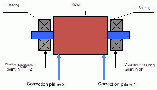
Vibration sensors are installed on the bearing supports at points 1 and 2. A revolution marker is attached to the rotor, usually with reflective tape. The RPM mark is used by the laser tachometer to determine the rotor speed and phase of the vibration signal.
متحرک توازن کیسے انجام دیا جاتا ہے (تھری رن طریقہ)
In most cases dynamic balancing is carried out by the method of three starts. The method is based on the fact that test weights of known weight are placed on the rotor in series in plane 1 and 2 and the weights and the location of the balancing weights are calculated based on the results of changes in the vibration parameters.
The place of installation of weights is called the correction plane. Usually the correction planes are selected in the area of the bearing supports on which the rotor is installed.
At the first start-up the initial vibration is measured. Then a test weight of known weight is placed on the rotor closer to one of the bearings. A second start-up is carried out and the vibration parameters are measured, which should change due to the test weight installation. Then the test weight in the first plane is removed and installed in the second plane. A third test run is performed and the vibration parameters are measured. The test weight is removed and the software automatically calculates the masses and installation angles of the balance weights.
The point of installing the test weights is to determine how the system reacts to changes in imbalance. The weights and locations of the test weights are known, so the software can calculate so called influence coefficients, showing how introducing a known imbalance affects the vibration parameters. The influence coefficients are characteristics of the mechanical system itself and depend on the rigidity of the supports and the mass (inertia) of the rotor-support system.
For the same type of mechanisms of the same design the influence coefficients will be close. It is possible to save them in the computer memory and use them for balancing of the same-type mechanisms without test runs, which significantly increases the productivity of balancing. Note that the mass of test weights should be chosen such that the vibration parameters change noticeably when test weights are installed. Otherwise, the error of calculation of influence coefficients increases and the quality of balancing deteriorates.
As you can see from Fig. 1, the centrifugal force acts in the radial direction, i.e. perpendicular to the rotor axis. Therefore, the vibration sensors must be installed so that their axis of sensitivity also points in the radial direction. Usually, the stiffness of the foundation in the horizontal direction is less, so the vibration in the horizontal direction is higher. Therefore, in order to increase the sensitivity, the sensors should be installed so that their axis of sensitivity is also directed horizontally. Although there is no fundamental difference. In addition to vibration in the radial direction, vibration in the axial direction, along the rotor rotation axis, must be monitored. This vibration is usually not caused by unbalance, but by other causes, mainly related to misalignment and misalignment of the shafts connected through the coupling.
اس کمپن کو توازن کے ذریعے ختم نہیں کیا جا سکتا، ایسی صورت میں سیدھ کی ضرورت ہوتی ہے۔ عملی طور پر، ایسی مشینوں میں عام طور پر روٹر کا عدم توازن اور شافٹ کی غلط ترتیب دونوں ہوتی ہیں، جو کمپن کو ختم کرنے کے کام کو بہت زیادہ مشکل بنا دیتا ہے۔ ایسی صورتوں میں، ضروری ہے کہ پہلے مشین کو سنٹر کیا جائے اور پھر اس میں توازن رکھا جائے۔ (اگرچہ مضبوط ٹارک کے عدم توازن کے ساتھ، فاؤنڈیشن کے ڈھانچے کے "موڑ" ہونے کی وجہ سے محوری سمت میں بھی کمپن ہوتی ہے۔)
متعلقہ مضامین (بیلنسنگ اسٹینڈز کی مثالیں)
- نرم سپورٹ کے ساتھ توازن قائم کرنا
- الیکٹرک موٹروں کے روٹرز کو متوازن کرنا
- Simple but effective balancing stands
بیلنسنگ میکانزم کے معیار کا اندازہ لگانے کا معیار
The balancing quality of rotors (mechanisms) can be evaluated in two ways. The first method involves comparing the amount of residual unbalance determined during the balancing process with the tolerance for residual unbalance. These tolerances for the different rotor classes are specified in ISO 1940-1-2007. Part 1. Definition of allowable unbalance.
However, compliance with the specified tolerances cannot fully guarantee the operational reliability of the mechanism, associated with the achievement of the minimum level of its vibration. This is explained by the fact that the magnitude of vibration of the mechanism is determined not only by the magnitude of the force associated with the residual unbalance of its rotor, but also depends on several other parameters, including: the rigidity k of the mechanism structural elements, its mass m, the damping factor, as well as the rotation frequency. Therefore, to estimate dynamic qualities of the mechanism (including quality of its balance) in a number of cases it is recommended to estimate the level of residual vibration of the mechanism, which is regulated by a number of standards.
The most common standard, which regulates the admissible levels of vibration of mechanisms is ISO 10816-3-2002. With its help, it is possible to set tolerances for any type of machines, taking into account the power of their electric drive.
In addition to this universal standard, there is a number of specialized standards developed for specific types of machines. For example, 31350-2007 , ISO 7919-1-2002, etc.
معیارات اور حوالہ جات
- ISO 1940-1:2007. کمپن. سخت روٹرز کے توازن کے معیار کے تقاضے حصہ 1۔ جائز عدم توازن کا تعین۔.
- ISO 10816-3:2009. مکینیکل وائبریشن — غیر گھومنے والے پرزوں پر پیمائش کے ذریعے مشین کے وائبریشن کا اندازہ — حصہ 3: صنعتی مشینیں جن کی برائے نام طاقت 15 کلو واٹ سے زیادہ اور برائے نام رفتار 120 r/min اور 15 000 r/min کے درمیان جب حالت میں ناپی جاتی ہے۔.
- آئی ایس او 14694:2003. صنعتی پرستار - توازن کے معیار اور کمپن کی سطحوں کے لیے وضاحتیں۔.
- ISO 7919-1:2002. مشینوں کا کمپن بغیر کسی حرکت کے - گھومنے والی شافٹ پر پیمائش اور تشخیص کے معیار - عمومی رہنمائی۔.
FAQ
کیا توازن تمام کمپن کو دور کرتا ہے؟
نہیں۔ غلط ترتیب، بیئرنگ نقائص، ایروڈائنامک/ہائیڈروڈینامک فورسز، برقی مقناطیسی قوتوں اور دیگر وجوہات سے ہونے والی کمپن کے لیے الگ الگ تشخیص اور اصلاحی اقدامات کی ضرورت ہوتی ہے۔.
گونج کے قریب توازن کیوں ناکام ہو سکتا ہے؟
گونج کے قریب، رفتار کی چھوٹی تبدیلیاں کمپن کے طول و عرض میں بڑی تبدیلیوں اور 180° فیز شفٹ کا سبب بن سکتی ہیں۔ ایسی حالتوں میں پیمائش کے نتائج غیر مستحکم ہو جاتے ہیں، اور روایتی توازن کے طریقہ کار خصوصی طریقوں کے بغیر نہیں مل سکتے ہیں۔.
آپ کو ایک ہوائی جہاز بمقابلہ دو ہوائی جہاز میں توازن کی کب ضرورت ہے؟
ایک سخت روٹر کے لیے، روٹر کی لمبائی کے ساتھ الگ الگ دو وزن عام طور پر ضروری اور مشترکہ جامد اور متحرک عدم توازن کو ختم کرنے کے لیے کافی ہوتے ہیں۔ تنگ گھومنے والے اکثر زیادہ تر جامد عدم توازن کو ظاہر کرتے ہیں، لیکن اخترتی اور جیومیٹری ایک متحرک جزو کو متعارف کروا سکتی ہے جس کے لیے دو طیاروں کی اصلاح کی ضرورت پڑسکتی ہے۔.
توازن قائم کرنے سے پہلے کیا کرنا چاہیے؟
اس بات کو یقینی بنائیں کہ مشین قابل استعمال ہے: فاؤنڈیشن پر قابل اعتماد نصب، صحت مند بیرنگ، کوئی شدید ڈھیلا پن، اور غیر خطوطی کا کوئی واضح ذریعہ نہیں۔ توازن مرمت کا متبادل نہیں ہے۔.
اہم نکات
- توازن ماس سے متعلق (مرکزی) جوش کو درست کرتا ہے۔ یہ غلط ترتیب، بیئرنگ نقصان، یا برقی مقناطیسی/ایروڈینامک ذرائع کو حل نہیں کرتا ہے۔.
- گونج اور غیر خطوطی روائتی توازن کو غیر موثر یا غیر محفوظ بنا سکتے ہیں۔.
- سخت روٹرز کے لیے، دو جہازوں کا توازن مشترکہ جامد + متحرک عدم توازن کا عمومی حل ہے۔.
