Combine Harvester Balancing: What I've Learned After Years of Doing It Wrong
I spent years thinking vibration was just part of running a combine. Turns out it wasn't. Here's everything I know about balancing drums, rotors, choppers, and the rest — the hard way, then the right way.

How I Went from "That's Normal" to "That's a Problem"
I'll be honest about this. For the first several years of working on combines, I thought vibration was just... the machine working. That's what combines do, right? They shake. Everything shakes. The cab shakes, the steering wheel buzzes in your hands, the bolts work themselves loose every few days, and you just tighten them again. That was the routine.
Then one day during harvest — peak season, of course, because problems always happen at peak season — the combine started shaking violently. Not the usual hum. This was the kind of vibration where you feel it in your teeth. Something was seriously wrong with the threshing drum. We'd replaced some beaters a couple weeks earlier, and nobody thought to check the balance afterward. Why would we? We'd been doing it that way for years.
That breakdown cost us three days. Three days in the middle of wheat harvest.
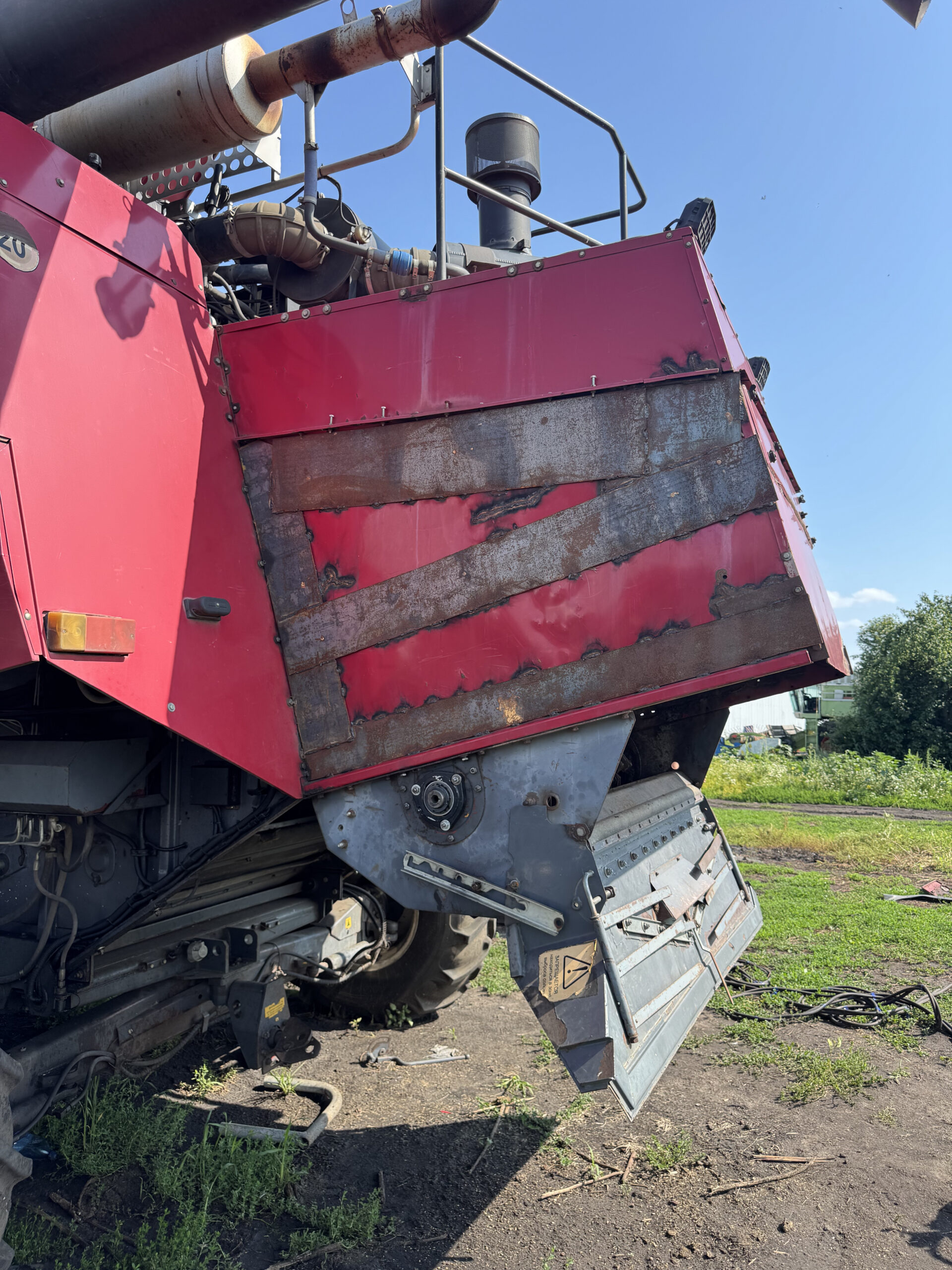
That's the picture that changed my mind. A colleague's combine — the straw walker housing literally ripped open from vibration. Bearings overheated, frame cracked at the welds, and the repair bill was more than what a portable balancer costs. Way more.
The thing about imbalance is it's sneaky. A heavy rotating part — drum, rotor, chopper — develops a "heavy side" over time. Wear, dirt buildup, a replaced blade that weighs 15 grams more than the old one. At 1,000 RPM, those 15 grams become a centrifugal force that hammers the bearings on every revolution. Thousands of times per minute. The bearings don't fail immediately. They fail mid-harvest, when you absolutely cannot afford downtime.
Main drum or rotor bearings — parts plus labor plus downtime
Waiting for parts, disassembly, repair, reassembly — mid-harvest
Average per assembly, on-site, no disassembly needed
Before I got the Balanset-1A, my options were limited. You could spin the drum on prisms and try to find the heavy side — that's static balancing, and it's better than nothing, but it only catches one type of imbalance. Dynamic imbalance — the kind that appears only at speed, when one end of a long drum is heavier than the other — you can't feel that on prisms. The drum rolls perfectly. Then you spin it up to 900 RPM and it tries to shake the combine apart.
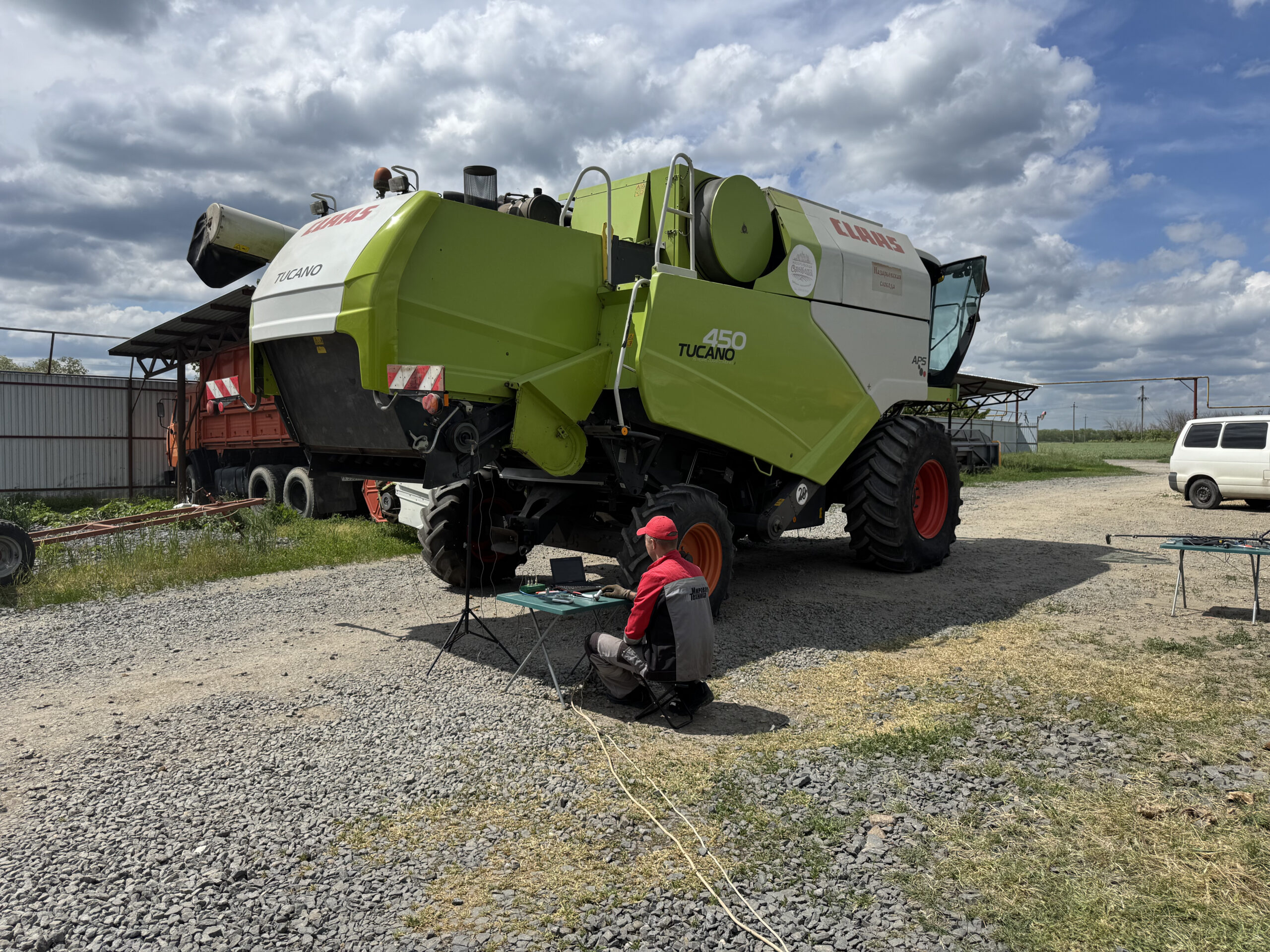
The Balanset-1A: What It Is and How I Use It

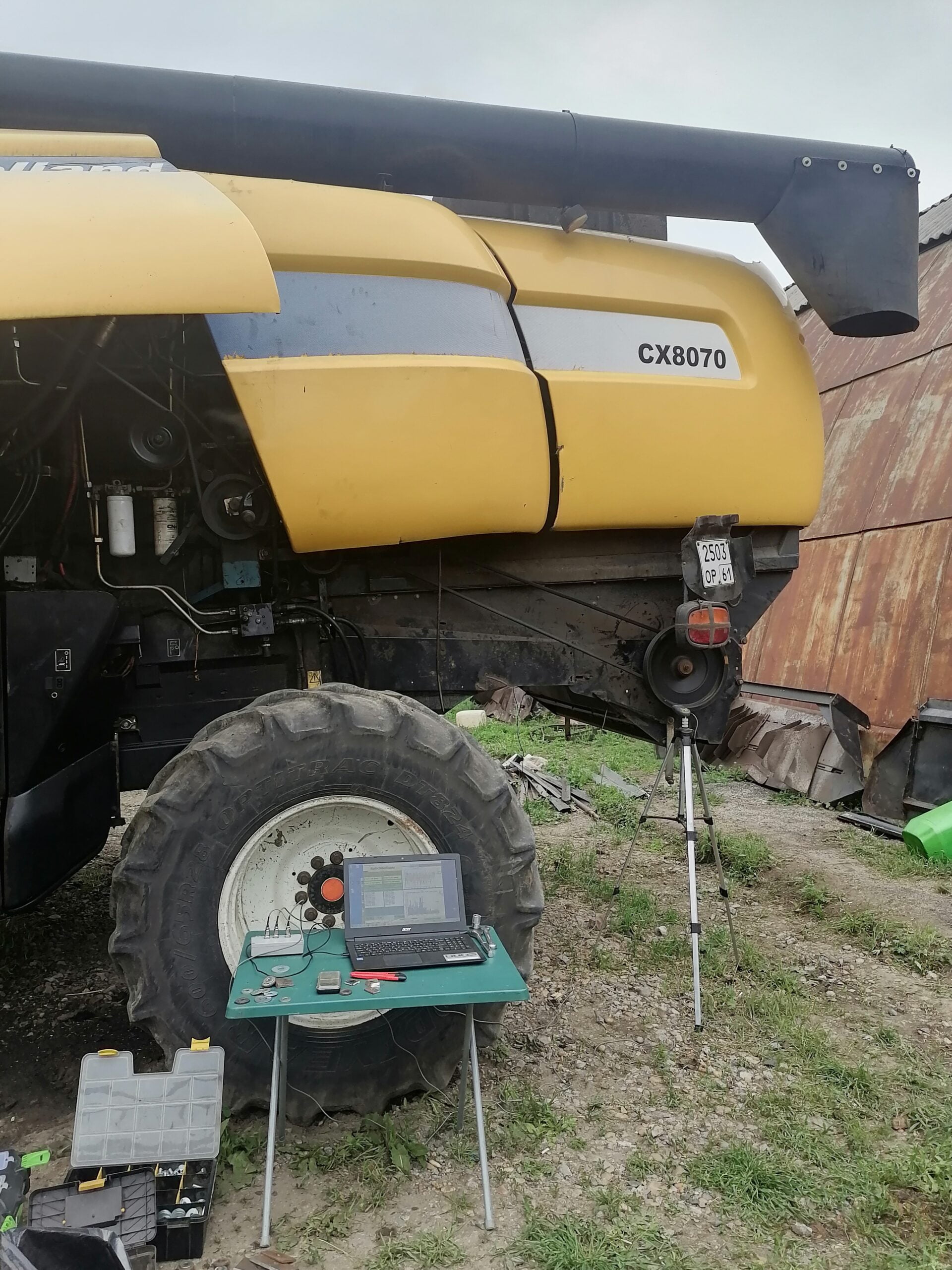
The kit is simple. Two vibration sensors (accelerometers) that attach magnetically to the bearing housings. A laser tachometer on a magnetic stand that reads a reflective mark on the rotating part — this tells the software exactly where the shaft is at every moment. An interface module that connects everything to a laptop via USB. Electronic scales for weighing trial weights. Reflective tape. The whole thing weighs about 4 kg and fits in a carrying case.
Here's what I actually do with it, stripped of all the technical language:
I attach the sensors. I launch the software. The software says "run the machine." I run it. Numbers appear — vibration level, and a phase angle that roughly tells me where the heavy spot is. Then the software says "stop, put a trial weight here." I bolt a steel plate to the drum at a specific position. Run it again. The software now has two readings — one without the weight, one with — and from the difference it calculates exactly how much metal to add and where. I weld it on. Run one more time to verify. Done.

The nice thing is I don't need to understand the math behind it. The software does the influence coefficient calculation. I just need to mount a weight where it tells me to and weigh it accurately. The first time I used it, I was nervous — I expected it to be complicated. It wasn't. The screen literally says "install 180 grams at 210 degrees on the left plane." That's it. I bolt a 180-gram plate at 210 degrees, run the combine, and the vibration drops from "I can feel it through the floor" to "the instrument barely registers it."
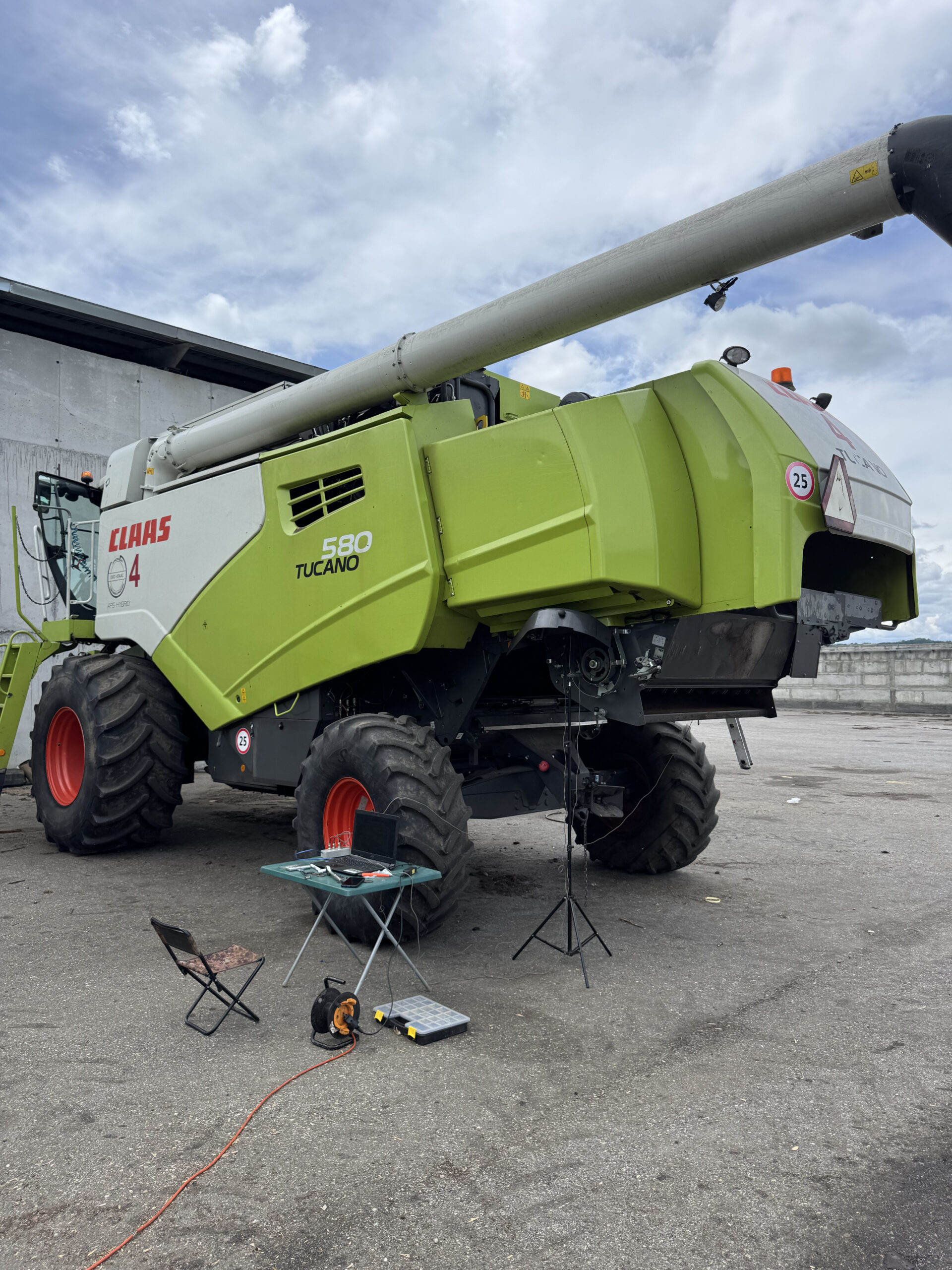
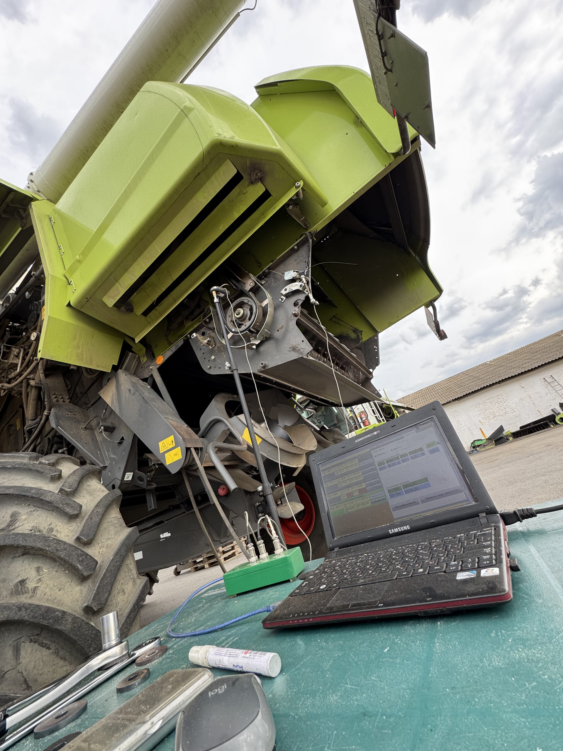
During balancing, the combine runs with covers open and a rotor spinning at operating speed. I always cordon off the area. Nobody stands near the spinning parts. I stay well back during measurement runs. This is the part you don't skip.
The Parts That Break: What Actually Needs Balancing in a Combine
Not everything in a combine needs balancing. But everything that rotates fast, carries heavy mass, and takes a beating from crop flow — that needs it. Here's the breakdown, roughly in order of how often I end up working on them:
Straw chopper rotor
The most frequent balancing job. Dozens of knives spinning at insane speeds. Every knife replacement shifts the balance. Missed it once — the housing cracked within a season.
Threshing drum
Heavy cylinder with beaters. Factory-balanced, but years of wear, dirt, replaced beaters, and welded cracks destroy that balance. Two-plane because it's long.
Rotary rotor (Axial-Flow)
Long shaft, large mass, handles both threshing and separation. Dirt packs into screw blades, metal bends, wear is uneven. Two-plane is mandatory.
Straw walker beater
Smaller drum after the threshing drum. Impact loading from uneven straw flow. Wet straw cements onto one side. After slat replacement — check balance.
Cleaning fan
Small mass, but runs at decent speed. Dust accumulation on blades, or a blade bent by a pebble. Low-mass corrections — need precise weighing.
Elevator augers
Grain and tailings augers. Lower speed, but wet grain packs on flights, flights bend from stones. Usually only balance after repair or straightening.
The Actual Procedure — How I Balance a Combine Assembly
I've done this enough times that it's become routine. But the first time felt like a lot. So here's exactly what happens, step by step, with the notes I wish someone had given me when I started.
Clean everything first
This is the step people want to skip, and it's the one that matters most. Get all the packed straw, mud, dust, and grain residue out. Pressure washer, scraper, compressed air — whatever it takes. I've had cases where cleaning alone dropped vibration by half. If you balance a dirty drum, you're correcting for the dirt — and next time the dirt shifts, your balance is gone.
While cleaning, inspect everything. Cracked beaters, worn knives, loose hub bolts, bent flights. Fix what you find. No point balancing a damaged rotor.
Mount sensors and tachometer
Accelerometers go on the bearing housings, radial direction (horizontal usually works best — stick them on with the magnet). For two-plane jobs, one sensor on each bearing. For single-plane, one sensor on the bearing closest to the rotating mass.
Stick reflective tape on the shaft end or on a visible rotating surface. Position the laser tachometer on its magnetic stand — it needs a clear line to the reflective mark. Plug everything into the Balanset-1A module, connect USB to the laptop, launch the software.
Run and record baseline (Run 0)
Start the combine, engage the drive for the assembly you're balancing. Let it reach operating speed. Wait for the readings to stabilize — usually 15–20 seconds. The software shows you vibration in mm/s and a phase angle in degrees.
This is your "before" number. I write it down on a sticky note too, because I like having it visible.
Trial weight — Plane 1 (Run 1)
Stop the machine. The software tells you to install a trial weight. I use a steel plate — bolt it or tack-weld it at a convenient position on one end of the rotor. Weigh it precisely on the electronic scales first. Enter the mass and angle into the software.
Run again. The software compares the new vibration to the baseline and calculates how the rotor responds to mass at that position. This is the "influence coefficient" — basically, the software learns the rotor's personality.
Trial weight — Plane 2 (Run 2, if two-plane)
For long rotors (threshing drum, rotary rotor), move the trial weight to the other end. Run again. Now the software has data from both planes and can calculate corrections that account for cross-coupling — the way mass at one end affects vibration at the other.
For disc-like parts (cleaning fan, single pulley), skip this — one plane is enough.
Install correction weights
The screen says something like: "Left plane: 85 g at 172°. Right plane: 42 g at 305°." Remove the trial weight. Cut or assemble steel plates to the right mass (this is where the electronic scales earn their keep). Weld or bolt them at the angles shown.
On beaters and chopper knives, I often use extra washers on the knife mounting bolts — simple, secure, doesn't change the blade geometry. On smooth drums, I tack-weld small plates. On auger flights, I bolt them.
Verify and finish
One more run. The software shows residual vibration. If it's below the target — typically under 2–3 mm/s for agricultural equipment — you're done. If not, the software suggests a trim correction. In my experience, about 80% of jobs are done after one correction pass. The chopper sometimes needs two iterations because the knife arrangement creates complex imbalance patterns.
Weld all correction weights permanently (full bead, not just tack). Save the report on the laptop. I keep a folder per machine with dates and before/after numbers — useful for tracking whether something is degrading over time.
Field Data: Numbers from Real Jobs
I'm going to be specific here because vague claims about "improved performance" don't help anyone. These are actual numbers from my work on combines over the past couple of seasons.
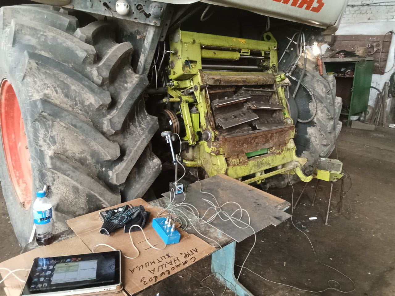
John Deere-type combine, after drum overhaul
Post-overhaul: three beaters replaced, shaft bearing seats reworked. The drum rolled fine on prisms (static balance OK). At operating speed, it shook the whole machine. Two-plane correction — 180 g at one end, 95 g at the other.
The rotary rotor job was different. This was a Claas-type axial-flow machine. The rotor had been running a full season without checks, and dirt had packed into the screw entry section unevenly. We cleaned it first (mandatory), but vibration was still elevated — the blades themselves had worn asymmetrically.


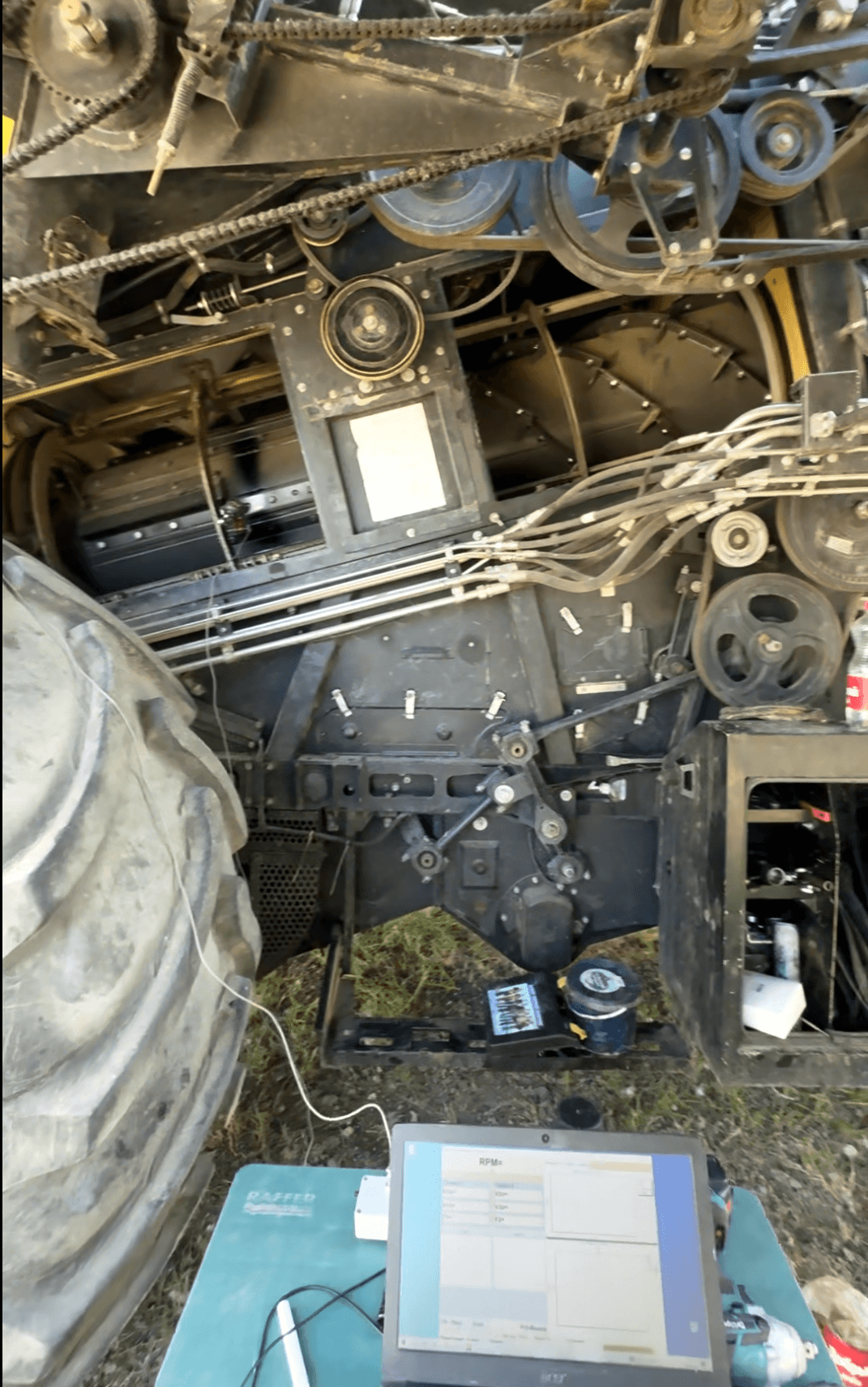

After two-plane correction: vibration dropped from 9.6 mm/s to 1.4 mm/s. The bearing temperature, which had been running 15°C above normal, came back down within a day. That rotor went the rest of the season without issues. Bearing replacement on a rotary rotor? I don't even want to think about the cost.
Tired of replacing bearings every season?
The Balanset-1A pays for itself after 2–3 jobs. One kit for every rotating assembly in the combine. No subscriptions, no recurring fees.
Straw Choppers: The Biggest Headache (and the Biggest Payoff)
I'm giving the chopper its own section because it's the component I balance most often and the one where I've seen the most dramatic failures.
Think about what a straw chopper is: a shaft with dozens of swinging knives (or hammers), spinning at 3,000–4,000 RPM. At that speed, even a few grams of imbalance produces enormous centrifugal force. And knives don't stay the same weight. They wear. They chip. They get replaced — and the replacement set is never exactly the same mass as what came off. People try to match knives in pairs by weight, which helps, but "close enough" at 4,000 RPM is not actually close enough.
Every time knives get replaced on the chopper — every single time — I check the balance. No exceptions. I've learned this the hard way. One time I skipped it because the knives were "matched pairs from the dealer." Three weeks later: housing crack. The imbalance was only 12 grams. Twelve grams, at 3,500 RPM, for three weeks — enough to crack steel.
The chopper balancing procedure is the same as everything else, but there are quirks. The high RPM means the tachometer positioning is more critical — the reflective mark goes by fast and the laser needs a clean read. I usually mount the tachometer on a separate stand rather than on the combine body, because the combine itself vibrates too much for a stable mount.
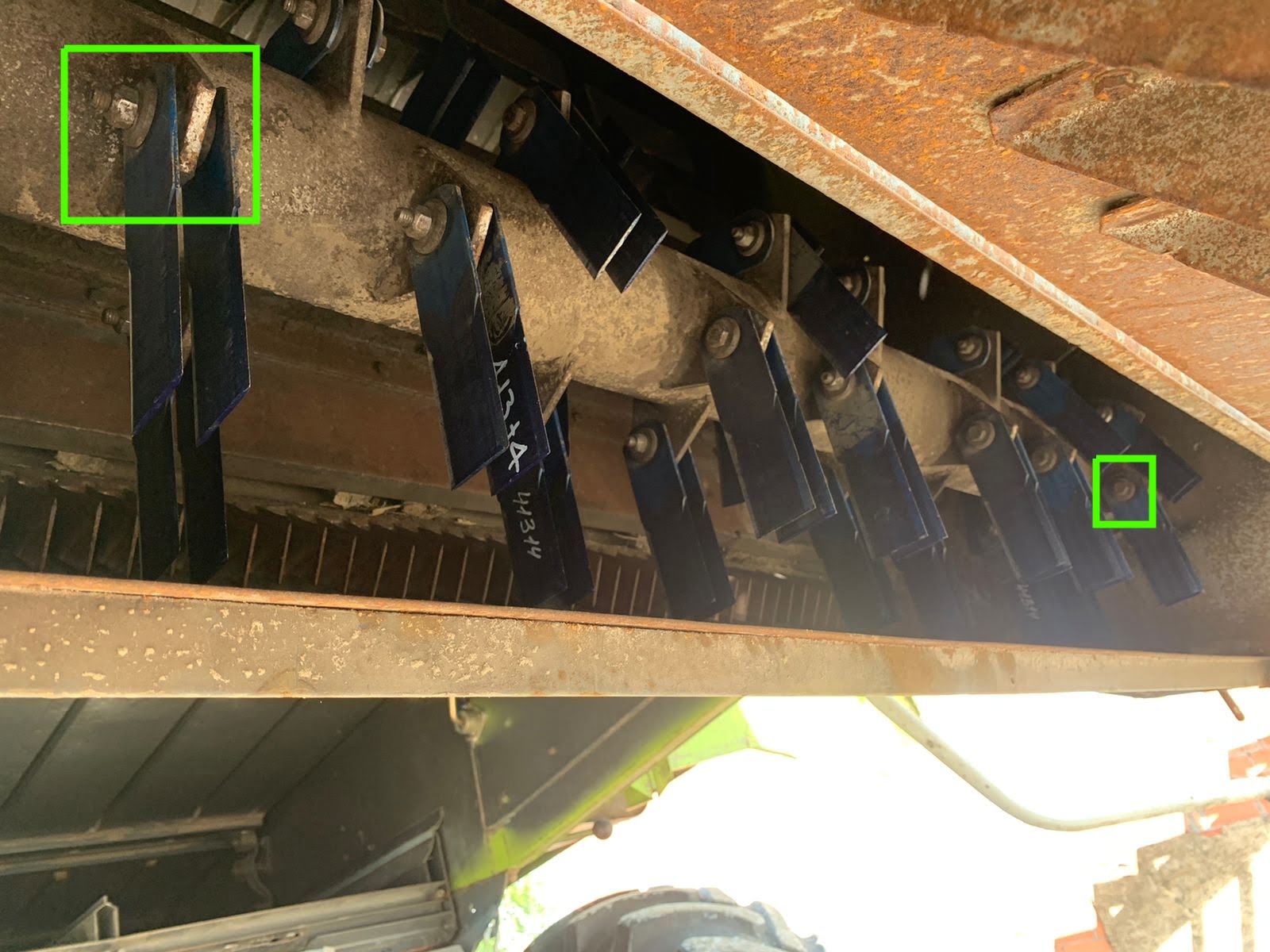

Sometimes the chopper needs two correction iterations. The first pass gets it close, but because the knives swing on their pivots, the mass distribution isn't perfectly rigid — it shifts slightly depending on speed. The second pass catches the residual. I budget 90 minutes for a chopper job.
But the payoff is real. A balanced chopper runs noticeably quieter — you can hear the difference from the cab. And the housing doesn't crack. The bearings don't overheat. The belts stop jumping. It's the single highest-value balancing job on the entire combine.
Pulleys, Flywheels, and Other Things People Forget
The cleaning fan is an easy one to overlook. It's small. But it runs at decent speed, and dust accumulates on the blades unevenly. I've balanced fans on two combines — both times after noticing that the cleaning wasn't as good as it should be (uneven airflow from an unbalanced fan means uneven sieve cleaning). Clean the blades first, then check vibration. Corrections are small — 5–10 grams — so precise weighing matters.
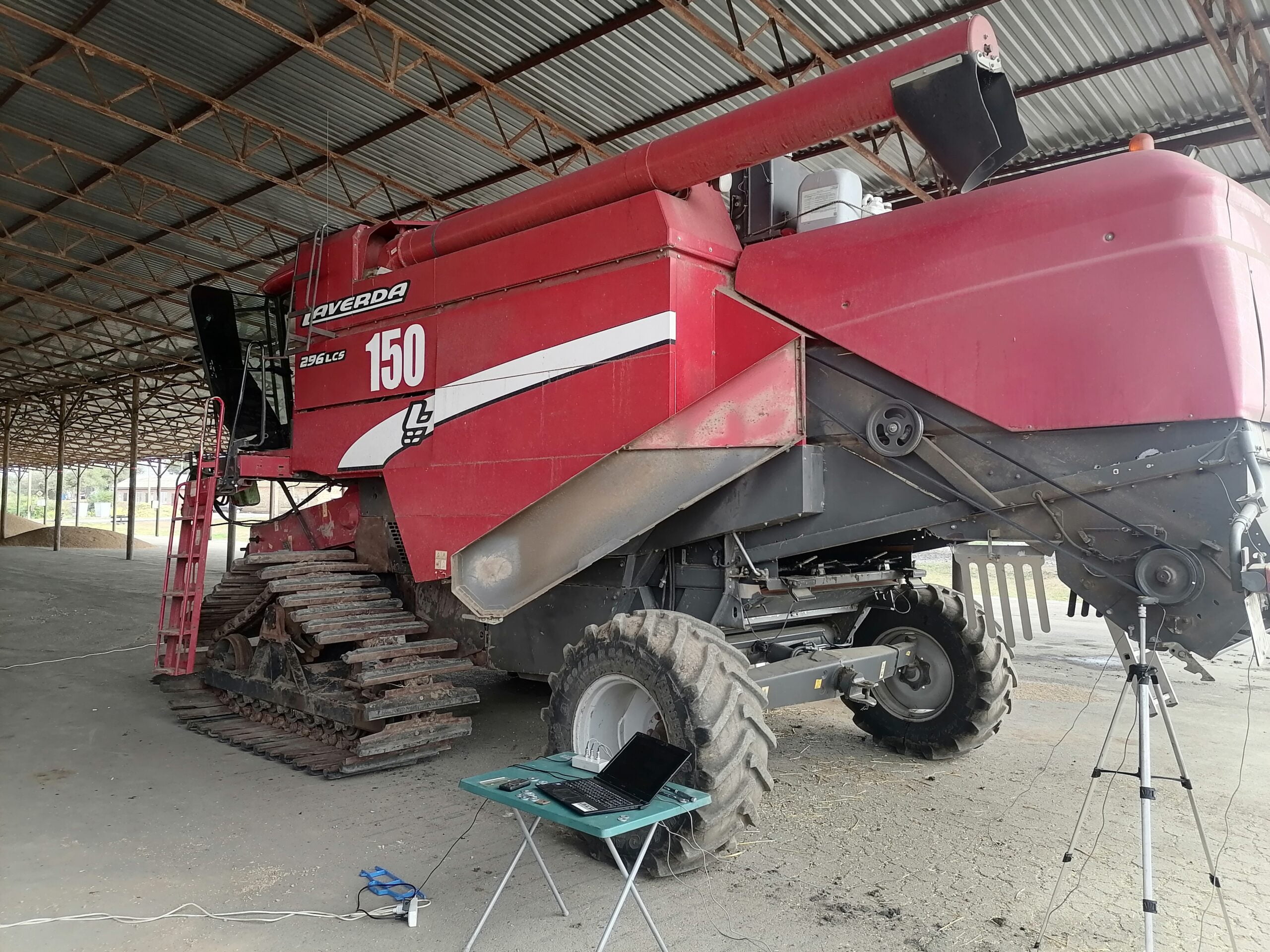
Elevator augers — grain and tailings — are lower speed but still worth checking after any repair. I once found an auger that had been straightened after hitting a stone, and the straightening wasn't quite right. The combine was making a rhythmic thumping sound that nobody could trace. Balanset-1A on the elevator housing found the problem in two minutes. A couple of small weights and the thumping was gone.
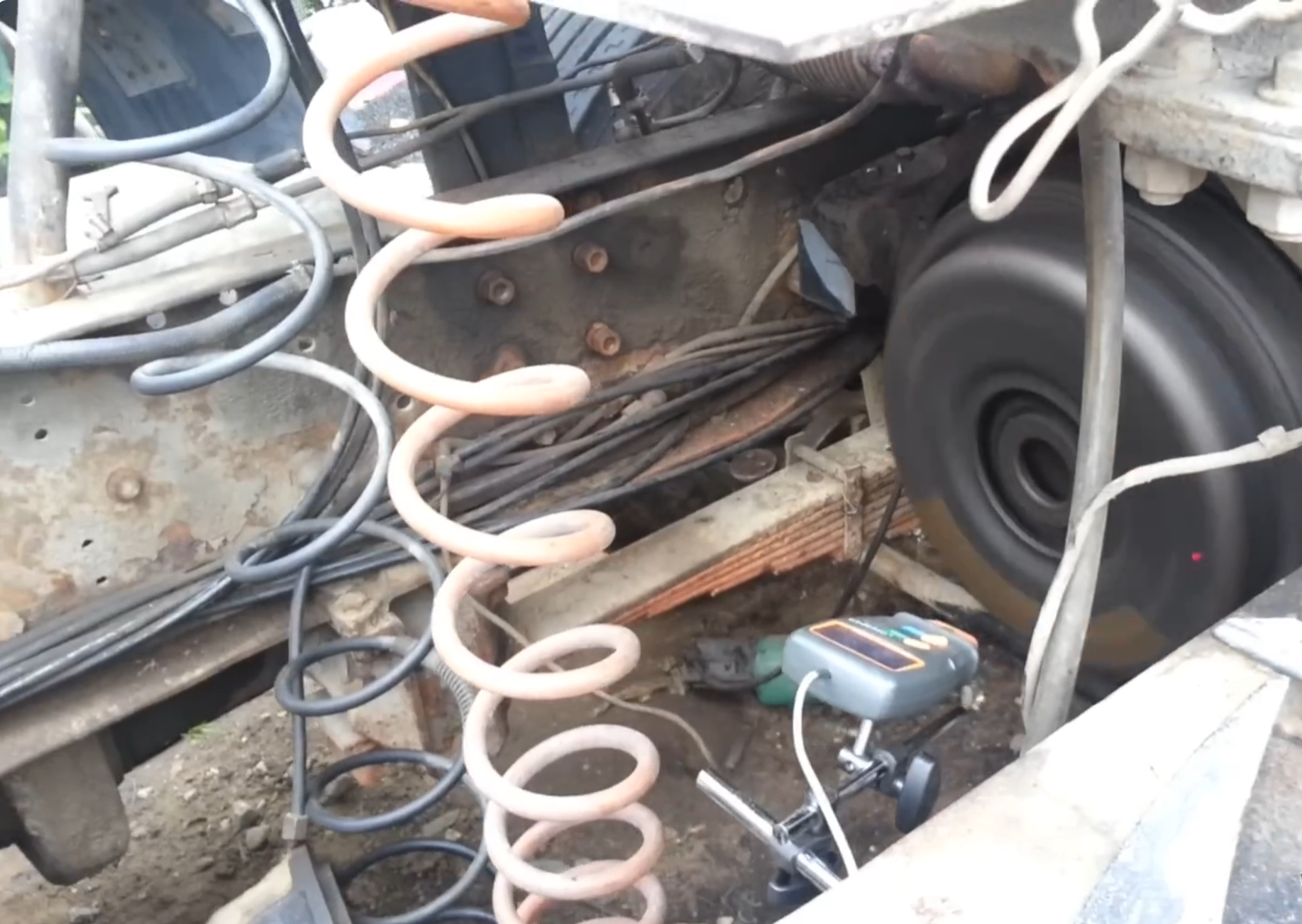
And then there are pulleys and flywheels. I don't balance these often — only when there's been repair work (bearing replacement, welding, reboring a seat). But I want to share one story that isn't technically about a combine, but the principle is the same.
We had a truck with engine vibration after a major overhaul. Nobody could find the cause. Mounts were fine, injectors were fine, timing was fine. I brought the Balanset-1A, attached a sensor to the engine block, put a reflective mark on the flywheel. Sure enough — the flywheel-clutch assembly was out of balance. Two washers on a mounting bolt, and the engine ran smooth. The mechanic who did the overhaul had re-machined the flywheel face and didn't check the balance afterward. Easy to miss, easy to fix — if you have the tool.
Balanset-1A Specs
For anyone wondering about the technical details of the Balanset-1A:
The kit covers everything: two accelerometers, laser tachometer with magnetic stand, interface module, USB cable, electronic scales, reflective tape, carrying case, software on USB. Plug into any laptop running Windows. No recurring license fees, no subscriptions, no "premium tier" nonsense. You buy it once.
Questions I Get Asked
One device. Every rotating part in the combine.
Balanset-1A. Drums, rotors, choppers, fans, augers, flywheels. Ships worldwide via DHL or UPS. 2-year warranty. Pays for itself after a couple of jobs.
The procedures described on this page were developed and field-tested by the Vibromera team using the Balanset-1A, a portable dual-channel balancer and vibration analyzer for on-site rotor balancing.

Nikolai Shelkovenko
Nikolai Shelkovenko is a vibration analysis engineer and the founder and CEO of Vibromera. For more than 15 years he has balanced rotating equipment in the field rather than on a test bench: mulchers, industrial fans, crushers, centrifuges, shafts and spindles. That work is what the Balanset instruments grew out of — they were designed as a tool a specialist can carry to the machine and use alone, on site, not as laboratory equipment. Vibromera was founded in 2017 and has been based in Porto, Portugal, since 2023. Development, assembly and support of the Balanset line all happen here. The flagship instrument is the Balanset-1A, a portable analyser for single- and two-plane balancing and for vibration diagnostics. Nikolai is personally involved in customer support, in working through difficult balancing cases and in the development of the software. He works with customers worldwide, in any language.


0 Comments