
PORTABLE BALANCER ""BALANSET-1A""
نظام موازنة ديناميكية ثنائي القناة يعتمد على الكمبيوتر الشخصي
OPERATION MANUAL
rev. 1.56 May 2023
2023 | البرتغال، بورتو
إشعار السلامة: هذا الجهاز متوافق مع معايير السلامة الأوروبية. منتج ليزر من الفئة 2. يُرجى اتباع إجراءات السلامة الخاصة بالمعدات الدوارة. انظر معلومات السلامة الكاملة أدناه →
1. نظرة عامة على نظام الموازنة
Balanset-1A balancer تقدم خدمات الموازنة الديناميكية أحادية وثنائية المستوى للمراوح وعجلات الطحن والمغازل والكسارات والمضخات وغيرها من الآلات الدوارة.
يشتمل جهاز موازنة Balanset-1A على مستشعري اهتزاز (مقياسي تسارع)، ومستشعر طور ليزري (مقياس سرعة الدوران)، ووحدة واجهة USB ثنائية القنوات مع مضخمات أولية، ومكاملات، ووحدة اكتساب بيانات ADC، وبرنامج موازنة يعمل بنظام Windows. يتطلب Balanset-1A جهاز كمبيوتر محمول أو أي جهاز كمبيوتر آخر متوافق مع نظام Windows (WinXP...Win11، بنظام 32 أو 64 بت).
Balancing software provides the correct balancing solution for single-plane and two-plane balancing automatically. Balanset-1A is simple to use for non-vibration experts.
All balancing results saved in archive and can be used to create the reports.
الميزات الرئيسية
سهل الاستخدام
- • كتلة تجريبية قابلة للتحديد من قبل المستخدم
- • نافذة منبثقة للتحقق من صحة كتلة التجربة
- • إدخال البيانات يدوياً
قدرات القياس
- • عدد الدورات في الدقيقة، والسعة، والطور
- • تحليل طيف تحويل فورييه السريع
- • عرض شكل الموجة والطيف
- • نقل البيانات المتزامنة عبر قناتين
وظائف متقدمة
- • معاملات التأثير المحفوظة
- • ضبط التوازن
- • حساب انحراف المندريل.
- • حسابات التفاوتات وفقًا لمعيار ISO 1940.
إدارة البيانات
- • سعة تخزين بيانات موازنة غير محدودة
- • تخزين شكل موجة الاهتزاز
- • الأرشيف والتقارير
أدوات الحساب
- • حساب الوزن المقسم
- • حسابات الحفر
- • تغيير مستويات التصحيح
- • تمثيل بياني قطبي
خيارات التحليل
- • قم بإزالة أو ترك أوزان التجربة
- • مخططات RunDown (تجريبية)
2. SPECIFICATION
| المعلمة | مواصفة |
|---|---|
| Measurement range of the root-mean-square value (RMS) of the vibration velocity, mm/sec (for 1x vibration) | from 0.02 to 100 |
| The frequency range of the RMS measurement of the vibration velocity, Hz | من 5 إلى 550 |
| Number of the correction planes | 1 or 2 |
| Range of the frequency of rotation measurement, rpm | 100 – 100000 |
| Range of the vibration phase measurement, angular degrees | from 0 to 360 |
| Error of the vibration phase measurement, angular degrees | ± 1 |
| دقة قياس سرعة الاهتزاز التربيعي المتوسط | ±(0.1 + 0.1×فولتتم قياسه) مم/ثانية |
| دقة قياس تردد الدوران | ±(1 + 0.005×Nتم قياسه) دورة في الدقيقة |
| متوسط الوقت بين الأعطال (MTBF)، ساعات، دقائق | 1000 |
| متوسط عمر الخدمة، سنوات، دقيقة | 6 |
| الأبعاد (في العلبة الصلبة)، سم | 39*33*13 |
| الكتلة، كجم | <5 |
| الأبعاد الكلية لمستشعر الاهتزاز، مم، الحد الأقصى | 25*25*20 |
| كتلة مستشعر الاهتزاز، كجم، الحد الأقصى | 0.04 |
|
ظروف التشغيل: - نطاق درجة الحرارة: من 5 درجات مئوية إلى 50 درجة مئوية - الرطوبة النسبية: أقل من 85%، غير مشبعة - بدون مجال كهرومغناطيسي قوي وتأثير قوي |
|
3. PACKAGE
يتضمن موازن Balanset-1A مقياسين للتسارع أحادي المحور، وعلامة مرجعية لمرحلة الليزر (مقياس سرعة الدوران الرقمي)، ووحدة واجهة USB ثنائية القناة مع مكبرات صوت مسبقة، ومُدمجات، ووحدة استحواذ على المحول التناظري الرقمي، وبرنامج موازنة قائم على نظام التشغيل Windows.
مجموعة التوصيل
| وصف | Number | Note |
|---|---|---|
| USB interface unit | 1 | |
| Laser phase reference marker (tachometer) | 1 | |
| مقاييس التسارع أحادية المحور | 2 | |
| Magnetic stand | 1 | |
| Digital scales | 1 | |
| Hard case for transportation | 1 | |
| ""Balanset-1A". دليل المستخدم. | 1 | |
| Flash disk with balancing software | 1 |
4. BALANCE PRINCIPLES
4.1. "يتضمن "Balanset-1A" (الشكل 4.1) وحدة واجهة USB (1)، مقياسين للتسارع (2) and (3)، علامة مرجعية للمرحلة (4) وجهاز كمبيوتر محمول (غير مرفق) (5).
تتضمن مجموعة التسليم أيضًا الحامل المغناطيسي (6) يستخدم لتركيب علامة مرجع الطور والمقاييس الرقمية 7.
X1 and X2 connectors intended for connection of the vibration sensors respectively to 1 and 2 measuring channels, and the X3 connector used for connection of the phase reference marker.
The USB cable provides power supply and connection of the USB interface unit to the computer.

الشكل 4.1. مجموعة توصيل "Balanset-1A""
تُسبب الاهتزازات الميكانيكية إشارة كهربائية تتناسب مع تسارع الاهتزاز على مخرج مستشعر الاهتزاز. تُنقل الإشارات الرقمية من وحدة المحول التناظري الرقمي عبر USB إلى الكمبيوتر المحمول. (5). يُولّد مُؤشّر الطور إشارة نبضية تُستخدم لحساب تردد الدوران وزاوية طور الاهتزاز. يُوفّر برنامج ويندوز حلولاً لموازنة المستويين، وتحليل الطيف، والرسوم البيانية، والتقارير، وتخزين مُعاملات التأثير.
5. SAFETY PRECAUTIONS
⚡ تنبيه - السلامة الكهربائية
5.1. When operating on 220V electrical safety regulations must be observed. It is not allowed to repair the device when connected to 220 V.
5.2. إذا كنت تستخدم الجهاز في بيئة طاقة تيار متردد منخفضة الجودة أو في وجود تداخل في الشبكة، فمن المستحسن استخدام طاقة مستقلة من بطارية الكمبيوتر.
⚠️ متطلبات السلامة الإضافية للمعدات الدوارة
- !قفل الآلة: قم دائمًا بتنفيذ إجراءات القفل/التعليق الصحيحة قبل تثبيت أجهزة الاستشعار
- !معدات الحماية الشخصية: ارتدِ نظارات السلامة وحماية السمع وتجنب الملابس الفضفاضة بالقرب من الآلات الدوارة
- !التثبيت الآمن: تأكد من تثبيت جميع أجهزة الاستشعار والكابلات بشكل آمن وعدم إمكانية تعطلها بواسطة الأجزاء الدوارة
- !إجراءات الطوارئ: معرفة موقع التوقفات الطارئة وإجراءات الإغلاق
- !تمرين: يجب على الموظفين المدربين فقط تشغيل معدات الموازنة على الآلات الدوارة
6. إعدادات البرامج والأجهزة
6.1. USB drivers and balancing software installation
Before working install drivers and balancing software.
قائمة المجلدات والملفات
Installation disk (flash drive) contains the following files and folders:
- Bs1Av###Setup – مجلد يحتوي على برنامج موازنة "Balanset-1A" (### – رقم الإصدار)
- أردرف - برامج تشغيل USB
- دليل EBalancer.pdf - هذا الدليل
- Bal1Av###Setup.exe ملف الإعداد. يحتوي هذا الملف على جميع الملفات والمجلدات المؤرشفة المذكورة أعلاه. ### – إصدار برنامج "Balanset-1A".
- Ebalanc.cfg - قيمة الحساسية
- بال.يني - بعض بيانات التهيئة
إجراء تثبيت البرنامج
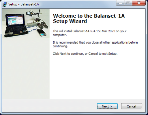
For installing drivers and specialized software run file Bal1Av###Setup.exe and follow setup instructions by pressing buttons «Next», «ОК» etc.
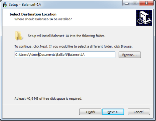
Choose setup folder. Usually the given folder should not be changed.
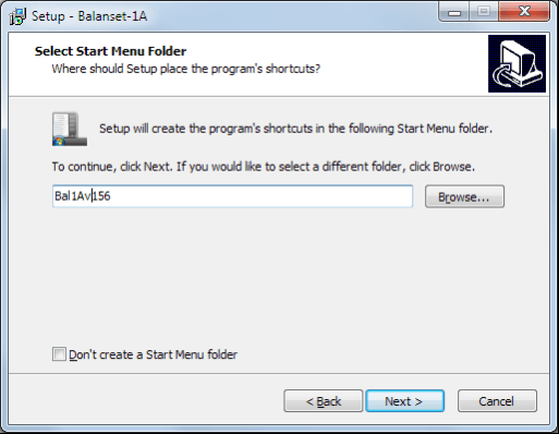
Then the program requires specifying Program group and desktop folders. Press button Next.
إتمام التركيب
- ✓Install sensors on the inspected or balanced mechanism (Detailed information about how to install the sensors is given in Annex 1)
- ✓Connect vibration sensors 2 and 3 to the inputs X1 and X2, and phase angle sensor to the input X3 of USB interface unit.
- ✓Connect USB interface unit to the USB-port of the computer.
- ✓عند استخدام مصدر طاقة تيار متردد، وصّل الكمبيوتر بمصدر الطاقة الرئيسي. وصّل مصدر الطاقة بجهد ٢٢٠ فولت، ٥٠ هرتز.
- ✓انقر على اختصار "Balanset-1A" على سطح المكتب.
7. برنامج الموازنة
7.1. عام
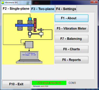
Initial window
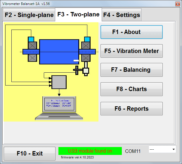
عند تشغيل البرنامج "Balanset-1A" تظهر النافذة الأولية، الموضحة في الشكل 7.1.

الشكل 7.1. النافذة الأولية لـ "Balanset-1A""
هناك 9 أزرار في النافذة الأولية مع أسماء الوظائف التي يتم تحقيقها عند النقر عليها.
F1-«About»
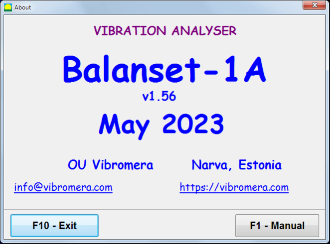
الشكل 7.2. نافذة F1 «حول»
F2-«Single plane», F3-«Two plane»
الضغط ""F2- مستوى واحد"" (أو F2 مفتاح الوظيفة على لوحة مفاتيح الكمبيوتر) يحدد اهتزاز القياس على القناة X1.
After clicking this button, the computer display diagram shown in Fig. 7.1 illustrating a process of measuring the vibration only on the first measuring channel (or the balancing process in a single plane).
الضغط على ""F3-مستويين"" (أو F3 function key on the computer keyboard) selects the mode of vibration measurements on two channels X1 and X2 simultaneously. (Fig. 7.3.)
الشكل 7.3. النافذة الأولية لـ "Balanset-1A". موازنة مستويين.
F4 – «الإعدادات»
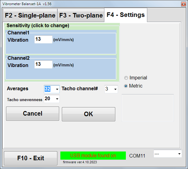
الشكل 7.4. نافذة "الإعدادات"
In this window you can change some Balanset-1A settings.
- Sensitivity. The nominal value is 13 mV / mm/s.
Changing the sensitivity coefficients of sensors is required only when replacing sensors!
انتباه!
عند إدخال معامل الحساسية، يتم فصل الجزء الكسري منه عن الجزء الصحيح بواسطة الفاصلة العشرية (العلامة ",").
- Averaging - عدد مرات حساب المتوسط (عدد دورات الدوار التي يتم حساب متوسط البيانات عليها للحصول على دقة أكبر)
- Tacho channel# - القناة # متصلة بجهاز قياس سرعة الدوران. افتراضياً - القناة الثالثة.
- Unevenness - الفرق في المدة بين نبضات مقياس سرعة الدوران المتجاورة، والذي يُعطي التحذير المذكور أعلاه ""Failure of the tachometer"
- Imperial/Metric - اختر نظام الوحدات.
Com port number is assigned automatically.
F5 – «مقياس الاهتزاز»
Pressing this button (or a function key of F5 (على لوحة مفاتيح الكمبيوتر) يقوم بتفعيل وضع قياس الاهتزاز على قناة قياس واحدة أو قناتين من قنوات قياس مقياس الاهتزاز الافتراضي، وذلك حسب حالة الأزرار."F2-مستوى واحد، ""F3-ذو مستويين".
F6 – «التقارير»
Pressing this button (or F6 function key on the computer keyboard) switches on the balancing Archive, from which you can print the report with the results of balancing for a specific mechanism (rotor).
F7 – «Balancing»
يؤدي الضغط على هذا الزر (أو مفتاح الوظيفة F7 على لوحة المفاتيح) إلى تنشيط وضع الموازنة في مستوى تصحيح واحد أو مستويين، وذلك حسب وضع القياس المحدد عن طريق الضغط على الأزرار."F2-مستوى واحد، ""F3-ذو مستويين".
F8 – «Charts»
Pressing this button (or F8 يتيح مفتاح الوظائف الموجود على لوحة مفاتيح الكمبيوتر (مقياس الاهتزاز الرسومي)، والذي يعرض على الشاشة في وقت واحد مع القيم الرقمية لسعة ومرحلة الاهتزاز الرسومي لوظيفته الزمنية.
F10 – «خروج»
Pressing this button (or F10 (مفتاح الوظيفة على لوحة مفاتيح الكمبيوتر) يكمل البرنامج "Balanset-1A".
7.2. "مقياس الاهتزاز""
قبل العمل في ""Vibration meter"في وضع التشغيل، قم بتثبيت مستشعرات الاهتزاز على الجهاز وقم بتوصيلها على التوالي بالموصلين X1 و X2 لوحدة واجهة USB. يجب توصيل مستشعر سرعة الدوران بالمدخل X3 لوحدة واجهة USB.

Fig. 7.5 USB interface unit
ضع شريطًا عاكسًا على سطح الدوار ليعمل عداد السرعة.
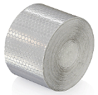
الشكل 7.6. شريط عاكس.
Recommendations for the installation and configuration of sensors are given in Annex 1.
لبدء القياس في وضع مقياس الاهتزاز، انقر على الزر ""F5 – Vibration Meter""في النافذة الأولية للبرنامج (انظر الشكل 7.1).
Vibration Meter window appears (see. Fig.7.7)

Fig. 7.7. Vibration meter mode. Wave and Spectrum.
لبدء قياسات الاهتزاز، انقر فوق الزر ""F9 – تشغيل"(أو اضغط على مفتاح الوظيفة) F9 on the keyboard).
لو وضع التشغيل التلقائي يتم التحقق - سيتم عرض نتائج قياسات الاهتزاز بشكل دوري على الشاشة.
في حالة القياس المتزامن للاهتزاز على القناتين الأولى والثانية، فإن النوافذ الموجودة أسفل الكلمات ""Plane 1"" و ""Plane 2"سيتم شغلها.
يمكن أيضًا إجراء قياس الاهتزاز في وضع "الاهتزاز" باستخدام مستشعر زاوية الطور غير المتصل. في النافذة الأولية للبرنامج، يتم عرض قيمة إجمالي جذر متوسط مربع الاهتزاز (V1s, V2s) will only be displayed.
هناك الإعدادات التالية في وضع مقياس الاهتزاز
- RMS منخفض، هرتز - أقل تردد لحساب RMS للاهتزاز الكلي
- عرض النطاق الترددي - نطاق تردد الاهتزاز في الرسم البياني
- Averages - عدد المتوسطات لمزيد من دقة القياس
لإكمال العمل في وضع "مقياس الاهتزاز"، انقر فوق الزر ""F10 – Exit""ثم العودة إلى النافذة الرئيسية.".

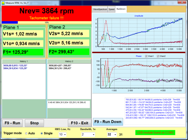
Fig. 7.8. Vibration meter mode. Rotation speed Unevenness, 1x vibration wave form.
Fig. 7.9. Vibration meter mode. Rundown (beta version, no warranty!).
7.3 إجراء الموازنة
يتم إجراء الموازنة للآليات ذات الحالة الفنية الجيدة والمثبتة بشكل صحيح. بخلاف ذلك، قبل إجراء الموازنة، يجب إصلاح الآلية وتركيبها في محامل مناسبة وتثبيتها. يجب تنظيف الدوار من الملوثات التي يمكن أن تعيق عملية التوازن.
قبل موازنة الاهتزاز، قم بقياس الاهتزاز في وضع مقياس الاهتزاز (زر F5) للتأكد من أن الاهتزاز بشكل أساسي هو اهتزاز 1x.
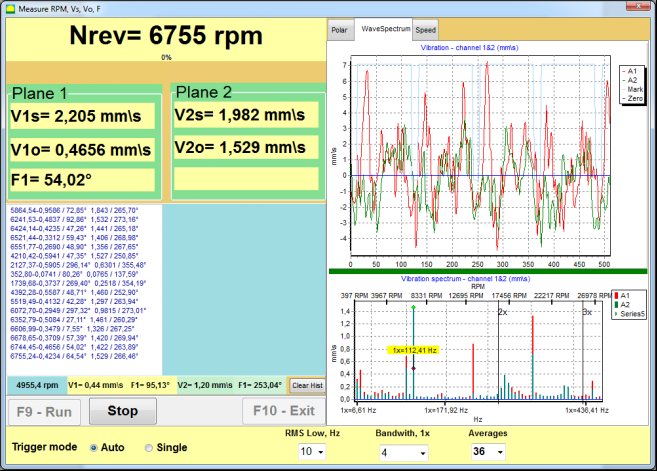
الشكل 7.10. وضع مقياس الاهتزاز. التحقق من الاهتزاز الشامل (V1s، V2s) و1x (V1o، V2o).
إذا كانت قيمة الاهتزاز الكلي V1s (V2s) مساوية تقريبًا لقيمة الاهتزاز عند تردد دوراني (اهتزاز 1x) V1o (V2o)، فيمكن افتراض أن السبب الرئيسي في آلية الاهتزاز هو اختلال توازن الدوار. إذا كانت قيمة الاهتزاز الكلي V1s (V2s) أعلى بكثير من قيمة مكون الاهتزاز 1x V1o (V2o)، يُنصح بفحص حالة الآلية - حالة المحامل، وتثبيتها على القاعدة، والتأكد من عدم وجود أي تلامس بين الأجزاء الثابتة والدوار أثناء الدوران، وما إلى ذلك.
يجب أيضًا مراعاة استقرار القيم المقاسة في وضع مقياس الاهتزاز - يجب ألا يتجاوز اتساع وطور الاهتزاز 10-15% أثناء عملية القياس. وإلا، يُمكن افتراض أن الآلية تعمل في نطاق قريب من الرنين. في هذه الحالة، غيّر سرعة دوران الدوار، وإذا تعذر ذلك، غيّر شروط تركيب الآلة على القاعدة (على سبيل المثال، ركّبها مؤقتًا على دعامات زنبركية).
لموازنة الدوار طريقة معامل التأثير ينبغي استخدام طريقة الموازنة (ثلاثية التشغيل).
يتم إجراء التجارب التجريبية لتحديد تأثير الكتلة التجريبية على تغير الاهتزازات والكتلة ومكان (زاوية) تركيب أوزان التصحيح.
حدد أولاً الاهتزاز الأصلي للآلية (ابدأ أولاً بدون وزن)، ثم اضبط الوزن التجريبي على المستوى الأول وقم بالبدء الثاني. ثم قم بإزالة الوزن التجريبي من المستوى الأول، ثم ضعه في المستوى الثاني وقم بالبدء الثاني.
يقوم البرنامج بعد ذلك بحساب ويشير على الشاشة إلى الوزن ومكان (زاوية) تركيب أوزان التصحيح.
عند الموازنة في مستوى واحد (ثابت)، لا يلزم البدء الثاني.
يتم ضبط الوزن التجريبي على موقع اختياري على الدوار حيث يكون مناسبًا، ثم يتم إدخال نصف القطر الفعلي في برنامج الإعداد.
(يُستخدم نصف قطر الموضع فقط لحساب كمية عدم الاتزان بالجرام * مم)
Important!
- يجب إجراء القياسات بسرعة دوران ثابتة للآلية!
- يجب تثبيت أوزان التصحيح على نفس نصف قطر الأوزان التجريبية!
يتم اختيار كتلة الوزن التجريبي بحيث تتغير سعة الاهتزاز بشكل ملحوظ بعد مرحلة التركيب (>20-30°) و(20-30%). إذا كانت التغييرات صغيرة جدًا، يزداد الخطأ بشكل كبير في الحسابات اللاحقة. اضبط كتلة الوزن التجريبي بسهولة في نفس موضع (نفس الزاوية) علامة الطور.
صيغة حساب كتلة الوزن التجريبي
Mt = Mr × Ksupport × Kvibration / (Rt × (N/100)²)
أين:
- جبل - كتلة الوزن التجريبي، جم
- السيد - كتلة الدوار، غرام
- كدعم - معامل صلابة الدعم (1-5)
- اهتزاز - معامل مستوى الاهتزاز (0.5-2.5)
- رت - نصف قطر تركيب وزن التجربة، سم
- ن - سرعة الدوار، دورة في الدقيقة
معامل صلابة الدعم (Ksupport):
- 1.0 - دعامات ناعمة جدًا (مخمدات مطاطية)
- 2.0-3.0 - صلابة متوسطة (المحامل القياسية)
- 4.0-5.0 - دعامات صلبة (أساسات ضخمة)
معامل مستوى الاهتزاز (Kvibration):
- 0.5 - اهتزاز منخفض (حتى 5 مم/ثانية)
- 1.0 - اهتزاز طبيعي (5-10 مم/ثانية)
- 1.5 - اهتزاز مرتفع (10-20 مم/ثانية)
- 2.0 - اهتزاز عالي (20-40 مم/ثانية)
- 2.5 - اهتزاز عالي جداً (>40 مم/ثانية)
🔗 استخدم الآلة الحاسبة عبر الإنترنت:
حاسبة الوزن التجريبي →⚠️ هام!
بعد كل اختبار تشغيل تتم إزالة الكتلة التجريبية! أثقال التصحيح الموضوعة بزاوية محسوبة من مكان تثبيت الوزن التجريبي في اتجاه دوران الدوار!
شرح حساب الزاوية:
زاوية تركيب وزن التصحيح هي دائماً يُحسب من نقطة تركيب الوزن التجريبي في اتجاه دوران الدوار.
- النقطة الصفرية (0°): يصبح الموقع الدقيق الذي قمت بتثبيت الوزن التجريبي فيه نقطة مرجعية (0 درجة).
- اتجاه: قم بقياس الزاوية في نفس اتجاه دوران الدوار.
مثال: إذا كان الدوار يدور في اتجاه عقارب الساعة، فقم بقياس الزاوية في اتجاه عقارب الساعة من موضع الوزن التجريبي. - تفسير: إذا كان البرنامج يعرض زاوية 120 درجة, ، يجب عليك تثبيت وزن التصحيح 120 درجة أمامك من موضع وزن التجربة في اتجاه الدوران.
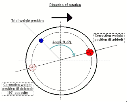
الشكل 7.11. تصحيح تركيب الوزن.
مُستَحسَن!
قبل إجراء الموازنة الديناميكية، يُنصح بالتأكد من أن اختلال التوازن الاستاتيكي ليس كبيرًا جدًا. بالنسبة للدوارات ذات المحور الأفقي، يُمكن تدوير الدوار يدويًا بزاوية 90 درجة من موضعه الحالي. إذا كان الدوار غير متوازن استاتيكيًا، فسيتم تدويره إلى وضع التوازن. بمجرد أن يتخذ الدوار وضع التوازن، من الضروري تثبيت وزن الموازنة في أعلى نقطة في منتصف طول الدوار تقريبًا. يجب اختيار الوزن بحيث لا يتحرك الدوار في أي موضع.
سيؤدي هذا التوازن المسبق إلى تقليل كمية الاهتزاز عند التشغيل الأول لدوار غير متوازن بشدة.
تركيب وتركيب المستشعر
الخامسيجب تثبيت مستشعر الاهتزاز على الجهاز في نقطة القياس المحددة وتوصيله بالمدخل X1 لوحدة واجهة USB.
هناك نوعان من تكوينات التثبيت:
- المغناطيس
- ترصيع الخيوط M4
يجب توصيل مستشعر سرعة الدوران البصري بمدخل X3 لوحدة واجهة USB. علاوة على ذلك، لاستخدام هذا المستشعر، يجب وضع علامة عاكسة خاصة على سطح الدوار.
📏 متطلبات تركيب المستشعر البصري
- ✓المسافة إلى سطح الدوار: 50-500 ملم (حسب طراز المستشعر)
- ✓عرض الشريط العاكس: الحد الأدنى 1-1.5 سم (يعتمد على السرعة ونصف القطر)
- ✓توجيه: عمودي على سطح الدوار
- ✓التركيب: استخدم حاملًا مغناطيسيًا أو مشبكًا للحصول على وضع ثابت
- ✓تجنب أشعة الشمس المباشرة أو إضاءة اصطناعية ساطعة على المستشعر/الشريط
💡 حساب عرض الشريط: للحصول على الأداء الأمثل، احسب عرض الشريط باستخدام:
L ≥ (N × R)/30000 ≥ 1.0-1.5 سم
حيث: L - عرض الشريط (سم)، N - سرعة الدوار (دورة في الدقيقة)، R - نصف قطر الشريط (سم)
المتطلبات التفصيلية حول اختيار الموقع لأجهزة الاستشعار وربطها بالجسم عند الموازنة موضحة في الملحق 1.
7.4 موازنة المستوى الواحد
الشكل 7.12. "موازنة المستوى الواحد"
أرشيف الموازنة
للبدء في العمل على البرنامج في ""موازنة الطائرة الواحدة""الوضع، انقر على ""F2-طائرة واحدة"زر " (أو اضغط على مفتاح F2 على لوحة مفاتيح الكمبيوتر).
ثم انقر على ""F7 – التوازن"زر "، وبعد ذلك أرشيف موازنة الطائرة الواحدة ستظهر نافذة يتم فيها حفظ بيانات الموازنة (انظر الشكل 7.13).

الشكل 7.13 نافذة اختيار أرشيف الموازنة في مستوى واحد.
في هذه النافذة، تحتاج إلى إدخال البيانات على اسم الدوار (اسم الدوار) مكان تركيب الدوار (مكان) ، التحمل للاهتزاز وعدم التوازن المتبقي (تسامح)، تاريخ القياس. يتم تخزين هذه البيانات في قاعدة بيانات. أيضًا، يتم إنشاء مجلد Arc###، حيث ### هو رقم الأرشيف الذي سيتم حفظ المخططات وملف التقرير وما إلى ذلك فيه. بعد اكتمال الموازنة، سيتم إنشاء ملف تقرير يمكن تحريره وطباعته في المحرر المدمج.
بعد إدخال البيانات المطلوبة، عليك النقر على ""F10-موافق"زر "، وبعد ذلك ""موازنة الطائرة الواحدة"سيتم فتح النافذة (انظر الشكل 7.13)
إعدادات الموازنة (طائرة واحدة)

الشكل 7.14. طائرة واحدة. إعدادات التوازن
يعرض الجانب الأيسر من هذه النافذة بيانات قياسات الاهتزاز وأزرار التحكم في القياس."تشغيل # 0", "تشغيل # 1", "RunTrim".
في الجانب الأيمن من هذه النافذة هناك ثلاث علامات تبويب:
- إعدادات التوازن
- الرسوم البيانية
- نتيجة
ال ""إعدادات التوازن"تُستخدم علامة التبويب " للدخول إلى إعدادات الموازنة:
- ""معامل التأثير"" -
- "روتور جديد"" - اختيار موازنة الدوار الجديد، الذي لا توجد له معاملات موازنة مخزنة ويتطلب تشغيلين لتحديد كتلة وزاوية تركيب وزن التصحيح.
- "معامل محفوظ."" - اختيار إعادة توازن الدوار، والتي يتم حفظ معاملات التوازن لها ولا يلزم سوى تشغيل واحد لتحديد وزن وزاوية تركيب الوزن التصحيحي.
- ""كتلة الوزن التجريبي"" -
- "نسبه مئويه""- يتم حساب الوزن التصحيحي كنسبة مئوية من وزن التجربة.".
- "غرام"يتم إدخال الكتلة المعروفة لوزن التجربة، ويتم حساب كتلة الوزن التصحيحي في جرامات أو في أوقية للنظام الامبراطوري.
⚠️ تنبيه! إذا كان من الضروري استخدام ""معامل محفوظ.""في وضع العمل الإضافي أثناء الموازنة الأولية، يجب إدخال كتلة وزن التجربة بالجرام أو الأونصة، وليس بوحدة %. الموازين مضمنة في عبوة التسليم.".
- ""طريقة ربط الأثقال""
- "موقف مجاني""- يمكن تركيب الأوزان في أوضاع زاوية عشوائية على محيط الدوار.".
- "موقف ثابت"يمكن تثبيت الأوزان في مواضع زاوية ثابتة على الدوّار، على سبيل المثال، على الشفرات أو الثقوب (مثلاً 12 ثقبًا - 30 درجة)، وما إلى ذلك. يجب إدخال عدد المواضع الثابتة في الحقل المخصص. بعد الموازنة، سيقوم البرنامج تلقائيًا بتقسيم الوزن إلى جزأين وتحديد عدد المواضع التي يجب تثبيت الأوزان عليها.
- "أخدود دائري"تُستخدم هذه الأداة لموازنة عجلات التجليخ. في هذه الحالة، تُستخدم 3 أثقال موازنة للتخلص من عدم التوازن.
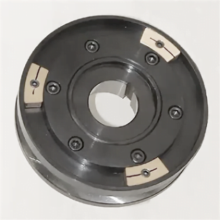
الشكل 7.17 موازنة عجلة الطحن بثلاثة أثقال موازنة
الشكل 7.18 موازنة عجلة الطحن. الرسم البياني القطبي.

الشكل 7.15. علامة التبويب النتيجة. موقف ثابت لتركيب الوزن التصحيحي.
Z1 وZ2 - موضعا الأوزان التصحيحية المُثبّتة، محسوبان من موضع Z1 وفقًا لاتجاه الدوران. Z1 هو موضع تثبيت الوزن التجريبي.
الشكل 7.16 المواضع الثابتة. المخطط القطبي.
- "نصف قطر التركيب الشامل، مم"" - "المستوى 1" - نصف قطر وزن التجربة في المستوى 1. يلزم حساب مقدار عدم التوازن الأولي والمتبقي لتحديد مدى الامتثال لتفاوت عدم التوازن المتبقي بعد الموازنة.
- "ترك الوزن التجريبي في Plane1."عادةً ما تتم إزالة وزن التجربة أثناء عملية الموازنة. ولكن في بعض الحالات يكون من المستحيل إزالته، وفي هذه الحالة يجب وضع علامة صح هنا لحساب كتلة وزن التجربة في الحسابات.
- "إدخال البيانات يدويا""- تُستخدم لإدخال قيمة الاهتزاز والطور يدويًا في الحقول المناسبة على الجانب الأيسر من النافذة، وحساب كتلة وزاوية تركيب وزن التصحيح عند التبديل إلى ""نتائج"" فاتورة غير مدفوعة
- زر ""استعادة بيانات الجلسة"أثناء عملية الموازنة، تُحفظ البيانات المقاسة في ملف session1.ini. إذا انقطعت عملية القياس بسبب تجمد الكمبيوتر أو لأسباب أخرى، فيمكنك استعادة بيانات القياس ومتابعة الموازنة من لحظة الانقطاع بالنقر على هذا الزر.
- إزالة انحراف الشياق (موازنة الفهرس) موازنة مع بداية إضافية للقضاء على تأثير الانحراف المركزي للشياق (موازنة الشجرة). قم بتركيب الدوار بالتناوب عند 0 درجة و 180 درجة بالنسبة إلى. قياس عدم التوازن في كلا الموقفين.
- موازنة التسامح إدخال أو حساب تفاوتات التفاوت المتبقية بـ gx mm (فئات G)
- استخدم الرسم البياني القطبي استخدم الرسم البياني القطبي لعرض نتائج الموازنة
1-موازنة الطائرة. الدوار الجديد
كما ذكر أعلاه، ""روتور جديد""تتطلب عملية الموازنة إجراء اختبارين وتشغيل واحد على الأقل لضبط آلة الموازنة.".
Run#0 (التشغيل الأولي)
بعد تركيب الحساسات على الدوار الموازن وإدخال معلمات الإعدادات، يجب تشغيل دوران الدوار، وعندما يصل إلى سرعة التشغيل، اضغط على ""Run#0"زر " لبدء القياسات"."الرسوم البيانية"ستُفتح علامة تبويب في اللوحة اليمنى، حيث سيتم عرض شكل الموجة وطيف الاهتزاز. في الجزء السفلي من علامة التبويب، يوجد ملف سجل، تُحفظ فيه نتائج جميع البدايات مع مرجع زمني. على القرص، يُحفظ هذا الملف في مجلد الأرشيف باسم memo.txt
انتباه!
قبل البدء في القياس، من الضروري تشغيل دوران الدوار لآلة الموازنة (Run#0) وتأكد من استقرار سرعة الدوار.
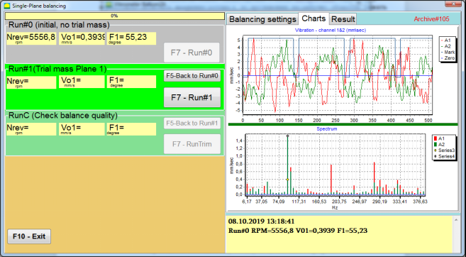
الشكل 7.19. التوازن في مستوى واحد. التشغيل الأولي (Run#0). علامة تبويب الرسوم البيانية
بعد الانتهاء من عملية القياس، في Run#0 يظهر في القسم الموجود في اللوحة اليسرى نتائج القياس - سرعة الدوران (RPM) و RMS (Vo1) والطور (F1) للاهتزاز 1x.
ال ""F5-العودة إلى Run#0"يتم استخدام الزر " (أو مفتاح الوظيفة F5) للعودة إلى قسم Run#0، وإذا لزم الأمر، لإعادة قياس معلمات الاهتزاز.
Run#1 (الطائرة الجماعية التجريبية 1)
قبل البدء في قياس معلمات الاهتزاز في القسم ""Run#1 (الطائرة الجماعية التجريبية 1), يجب تركيب وزن تجريبي وفقًا لـ"كتلة الوزن التجريبي"" مجال.
الهدف من تثبيت الوزن التجريبي هو تقييم كيفية تغير اهتزاز الدوار عند تثبيت وزن معروف في مكان (زاوية) معروفة. يجب أن يغير الوزن التجريبي سعة الاهتزاز بمقدار 30% أقل أو أعلى من السعة الأولية أو مرحلة التغيير بمقدار 30 درجة أو أكثر من الطور الأولي.
إذا كان من الضروري استخدام ""معامل محفوظ.""لموازنة العمل اللاحق، يجب أن يكون مكان (زاوية) تركيب وزن الاختبار هو نفسه مكان (زاوية) العلامة العاكسة.
أعد تشغيل دوران دوار جهاز الموازنة وتأكد من ثبات تردد دورانه. ثم انقر على ""F7-Run#1"زر " (أو اضغط على مفتاح F7 على لوحة مفاتيح الكمبيوتر).
بعد القياس في النوافذ المقابلة لـ ""Run#1 (الطائرة الجماعية التجريبية 1)"القسم "، نتائج قياس سرعة الدوران (RPM)، بالإضافة إلى قيمة مكون RMS (Vо1) والطور (F1) للاهتزاز 1x الذي يظهر.
وفي الوقت نفسه، فإن ""نتيجة""تفتح علامة التبويب على الجانب الأيمن من النافذة.".
تعرض علامة التبويب هذه نتائج حساب الكتلة وزاوية الوزن التصحيحي التي يجب تثبيتها على الدوار لتعويض الخلل.
علاوة على ذلك، في حالة استخدام نظام الإحداثيات القطبية، تعرض الشاشة قيمة الكتلة (M1) وزاوية التثبيت (f1) لوزن التصحيح.
في حالة ""مواقف ثابتة"سيتم عرض أرقام المواضع (Zi، Zj) ووزن التجربة بعد تقسيم الكتلة.
الشكل 7.20. التوازن في مستوى واحد. Run#1 ونتيجة الموازنة.
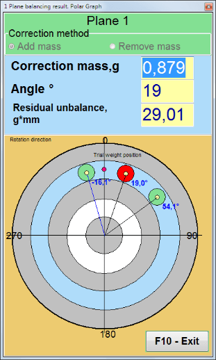
لو الرسم البياني القطبي سيتم عرض الرسم البياني القطبي.
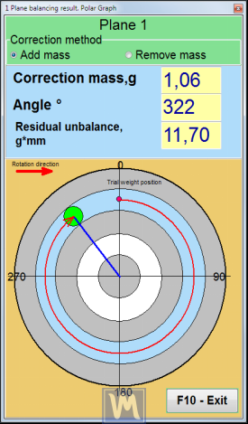
الشكل 7.21. نتيجة التوازن. الرسم البياني القطبي.
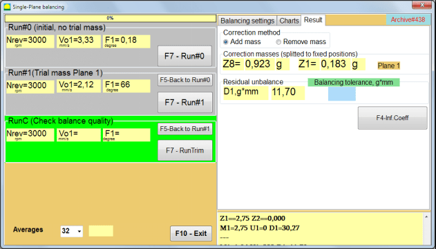
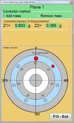
الشكل 7.22. نتيجة التوازن. الوزن المقسم (المواضع الثابتة)
أيضًا إذا ""الرسم البياني القطبي"تم التحقق من "، سيتم عرض الرسم البياني القطبي.
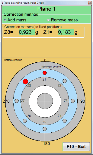
الشكل 7.23. الوزن مقسم على مواضع ثابتة. الرسم البياني القطبي
⚠️ تنبيه!
- بعد إتمام عملية القياس في الجولة الثانية (""Run#1 (الطائرة الجماعية التجريبية 1)"عند استخدام جهاز الموازنة، يجب إيقاف الدوران وإزالة وزن الاختبار المُثبّت. ثم قم بتركيب (أو إزالة) وزن التصحيح على الدوّار وفقًا لبيانات جدول النتائج.
إذا لم تتم إزالة وزن التجربة، فيجب عليك التبديل إلى ""إعدادات التوازن""انقر على علامة التبويب وقم بتشغيل خانة الاختيار في ""ترك الوزن التجريبي في Plane1"ثم انتقل مرة أخرى إلى"نتيجة"" علامة تبويب. يتم إعادة حساب وزن وزاوية تركيب وزن التصحيح تلقائيًا.
- يُحدَّد الوضع الزاوي للثقل التصحيحي من مكان تركيب الثقل التجريبي. يتطابق اتجاه مرجع الزاوية مع اتجاه دوران الدوار.
- في حالة ""موقف ثابت"- الأولشارع الموضع (Z1) يتزامن مع مكان تركيب الوزن التجريبي. اتجاه العد لرقم الموضع هو في اتجاه دوران الدوار.
- بشكل افتراضي، ستتم إضافة الوزن التصحيحي إلى الدوار. ويُشار إلى ذلك بواسطة الملصق المحدد في ""يضيف""الحقل. إذا قمت بإزالة الوزن (على سبيل المثال، عن طريق الحفر)، فيجب عليك وضع علامة في ""يمسح""الحقل، وبعد ذلك سيتغير الوضع الزاوي لوزن التصحيح تلقائيًا بمقدار 180 درجة.
بعد تثبيت وزن التصحيح على دوار الموازنة في نافذة التشغيل، من الضروري إجراء RunC (التشذيب) وتقييم فعالية الموازنة التي تم إجراؤها.
RunC (التحقق من جودة الرصيد)
⚠️ تنبيه! قبل البدء بالقياس على RunC، من الضروري تشغيل دوران دوار الماكينة والتأكد من دخوله في وضع التشغيل (تردد الدوران المستقر).
لإجراء قياس الاهتزاز في ""RunC (التحقق من جودة الرصيد)"انقر على "القسم"."F7 - رنتريم"زر " (أو اضغط على مفتاح F7 على لوحة المفاتيح).
بعد إتمام عملية القياس بنجاح، في ""RunC (التحقق من جودة الرصيد)"في القسم الموجود في اللوحة اليسرى، تظهر نتائج قياس سرعة الدوران (RPM)، بالإضافة إلى قيمة مكون RMS (Vo1) والطور (F1) للاهتزاز 1x.
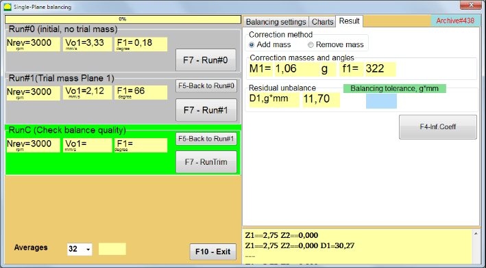
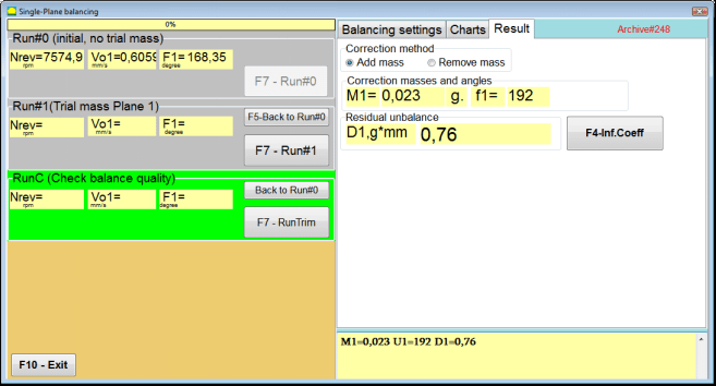
في ""نتيجة"" علامة التبويب، يتم عرض نتائج حساب كتلة وزاوية تركيب الوزن التصحيحي الإضافي.
الشكل 7.24. التوازن في مستوى واحد. تنفيذ RunTrim. علامة التبويب النتيجة
يمكن إضافة هذا الوزن إلى وزن التصحيح المثبت بالفعل على الدوار للتعويض عن الخلل المتبقي. بالإضافة إلى ذلك، يتم عرض عدم التوازن المتبقي للدوار بعد الموازنة في الجزء السفلي من هذه النافذة.
في حالة استيفاء مقدار الاهتزاز المتبقي و/أو عدم الاتزان المتبقي للدوار المتوازن لمتطلبات التسامح المنصوص عليها في الوثائق الفنية، يمكن إكمال عملية الموازنة.
وإلا فإن عملية التوازن قد تستمر. يتيح ذلك لطريقة التقريبات المتعاقبة تصحيح الأخطاء المحتملة التي قد تحدث أثناء تركيب (إزالة) الوزن التصحيحي على الدوار المتوازن.
عند مواصلة عملية الموازنة على دوار الموازنة، من الضروري تركيب (إزالة) كتلة تصحيحية إضافية، وتُبين معاييرها في القسم ""تصحيح الكتل والزوايا".
معاملات التأثير (طائرة واحدة)
ال ""F4-Inf.Coeff"زر " في ""نتيجة"تُستخدم علامة التبويب " لعرض وتخزين معاملات موازنة الدوار (معاملات التأثير) المحسوبة من نتائج عمليات المعايرة في ذاكرة الكمبيوتر.
عند الضغط عليه، ""معاملات التأثير (طائرة واحدة)"تظهر نافذة على شاشة الكمبيوتر، تعرض معاملات الموازنة المحسوبة من نتائج عمليات المعايرة (الاختبار). إذا كان من المفترض استخدام هذه النافذة أثناء عملية الموازنة اللاحقة لهذه الآلة،"معامل محفوظ.""الوضع، يجب تخزين هذه المعاملات في ذاكرة الكمبيوتر.".
للقيام بذلك، انقر فوق ""F9 - حفظ"انقر على الزر وانتقل إلى الصفحة الثانية من ""أرشيف معامل التأثير. مستوى واحد."

الشكل 7.25. موازنة المعاملات في المستوى الأول
ثم عليك إدخال اسم هذه الآلة في ""الدوار""عمود وانقر""F2-حفظ"زر "حفظ البيانات المحددة على الكمبيوتر".
ثم يمكنك العودة إلى النافذة السابقة بالضغط على ""F10-خروج"زر " (أو مفتاح الوظيفة F10 على لوحة مفاتيح الكمبيوتر).
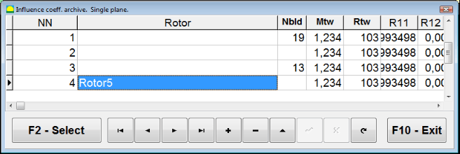
الشكل 7.26. "معامل التأثير. أرشيف. مستوى واحد.""
تقرير الموازنة
بعد موازنة جميع البيانات، يتم حفظها وإنشاء تقرير الموازنة. يمكنك عرض التقرير وتحريره في المحرر المدمج. في النافذة ""موازنة الأرشيف في مستوى واحد"" (الشكل 7.9) اضغط على الزر ""F9 -تقرير""للوصول إلى محرر تقرير الموازنة".
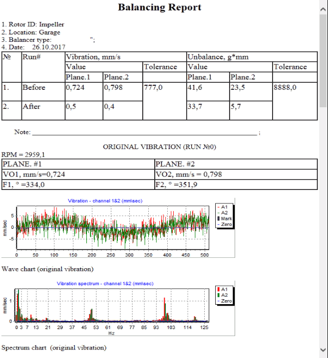
الشكل 7.27. تقرير الموازنة.
إجراء موازنة معامل الحفظ مع معاملات التأثير المحفوظة في مستوى واحد
إعداد نظام القياس (إدخال البيانات الأولية)
معامل محفوظ. موازنة يمكن إجراؤها على جهاز تم بالفعل تحديد معاملات موازنة له وإدخالها في ذاكرة الكمبيوتر.
⚠️ تنبيه! عند الموازنة مع المعاملات المحفوظة، يجب تثبيت مستشعر الاهتزاز ومستشعر زاوية الطور بنفس الطريقة التي تم بها أثناء الموازنة الأولية.
إدخال البيانات الأولية ل معامل محفوظ. موازنة (كما في حالة الأساسي(""الدوار الجديد"") التوازن) يبدأ في ""موازنة طائرة واحدة. إعدادات التوازن.".
في هذه الحالة، في ""معاملات التأثير""القسم، حدد ""معامل محفوظ""البند". في هذه الحالة، الصفحة الثانية من ""معامل التأثير. أرشيف. طائرة واحدة."."، الذي يخزن أرشيفًا لمعاملات الموازنة المحفوظة.
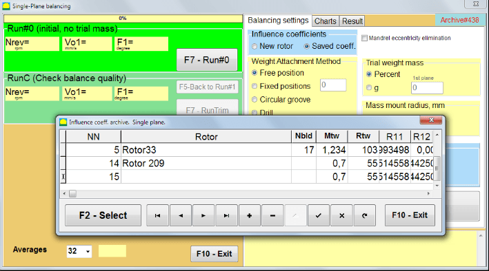
الشكل 7.28. الموازنة مع معاملات التأثير المحفوظة في مستوى واحد
باستخدام زري التحكم "►" أو "◄" للتنقل بين صفحات هذا الأرشيف، يمكنك تحديد السجل المطلوب الذي يحتوي على معاملات موازنة الجهاز الذي يهمنا. بعد ذلك، لاستخدام هذه البيانات في القياسات الحالية، اضغط على ""F2 - اختر"" زر.
بعد ذلك، محتويات جميع النوافذ الأخرى من ""موازنة طائرة واحدة. إعدادات التوازن."يتم ملء الحقول تلقائيًا.
بعد الانتهاء من إدخال البيانات الأولية، يمكنك البدء في القياس.
القياسات أثناء الموازنة باستخدام معاملات التأثير المحفوظة
تتطلب الموازنة باستخدام معاملات التأثير المحفوظة تشغيلًا أوليًا واحدًا فقط وتشغيلًا اختباريًا واحدًا على الأقل لآلة الموازنة.
⚠️ تنبيه! قبل البدء في القياس، من الضروري تشغيل دوران الدوار والتأكد من استقرار تردد الدوران.
لإجراء قياس معلمات الاهتزاز في ""Run#0 (الأولي، لا يوجد كتلة تجريبية)""القسم، اضغط""F7 - Run#0"(أو اضغط على مفتاح F7 على لوحة مفاتيح الكمبيوتر).
الشكل 7.29. الموازنة مع معاملات التأثير المحفوظة في مستوى واحد. النتائج بعد تشغيل واحد.
في الحقول المقابلة لـ ""Run#0""القسم، تظهر نتائج قياس سرعة الدوار (RPM)، وقيمة مكون RMS (Vо1) والطور (F1) للاهتزاز 1x.
وفي الوقت نفسه، فإن ""نتيجة"تعرض علامة التبويب " " نتائج حساب كتلة وزاوية الوزن التصحيحي، والذي يجب تركيبه على الدوار لتعويض عدم التوازن.
علاوة على ذلك، في حالة استخدام نظام إحداثيات قطبية، تعرض الشاشة قيم الكتلة وزوايا التثبيت لأوزان التصحيح.
في حالة تقسيم الوزن التصحيحي على المواضع الثابتة يتم عرض أرقام مواضع دوار الموازنة وكتلة الوزن المطلوب تثبيتها عليها.
علاوة على ذلك، يتم تنفيذ عملية الموازنة وفقًا للتوصيات الواردة في القسم 7.4.2. للموازنة الأولية.
إزالة انحراف الشياق (موازنة الفهرس)
إذا تم تثبيت الدوار في شياق أسطواني أثناء الموازنة، فإن انحراف الشياق قد يؤدي إلى حدوث خطأ إضافي. للتخلص من هذا الخطأ، يجب نشر الدوار في الشياق بمقدار 180 درجة وتنفيذ بداية إضافية. وهذا ما يسمى موازنة الفهرس.
لتنفيذ موازنة الفهرس، يتم توفير خيار خاص في برنامج Balanset-1A. عند تحديد إزالة انحراف مغزل الشياق، يظهر قسم RunEcc إضافي في نافذة الموازنة.

الشكل 7.30. نافذة العمل لموازنة الفهرس.
بعد تشغيل Run # 1 (المستوى التجريبي 1)، ستظهر نافذة
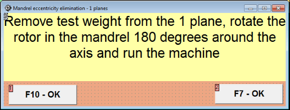
الشكل 7.31 نافذة الانتباه لموازنة الفهرس.
بعد تثبيت الدوار بزاوية ١٨٠ درجة، يجب إكمال تشغيل برنامج Run Ecc. سيحسب البرنامج تلقائيًا اختلال التوازن الحقيقي للدوار دون التأثير على مركزية محور الدوران.
7.5 موازنة المستويين
Before starting work in the Two plane balancing mode, it is necessary to install vibration sensors on the machine body at the selected measurement points and connect them to the inputs X1 and X2 of the measuring unit, respectively.
An optical phase angle sensor must be connected to input X3 of the measuring unit. In addition, to use this sensor, a reflective tape must be glued onto the accessible rotor surface of the balancing machine.
Detailed requirements for choosing the installation location of sensors and their mounting at the facility during balancing are set out in Appendix 1.
العمل على البرنامج في ""Two plane balancing"يبدأ الوضع من النافذة الرئيسية للبرامج.
انقر على ""F3-Two plane"زر " (أو اضغط على مفتاح F3 على لوحة مفاتيح الكمبيوتر).
علاوة على ذلك، انقر فوق الزر "F7 - الموازنة"، وبعد ذلك ستظهر نافذة عمل على شاشة الكمبيوتر (انظر الشكل 7.13)، وتحديد الأرشيف لحفظ البيانات عند الموازنة في مستويين.
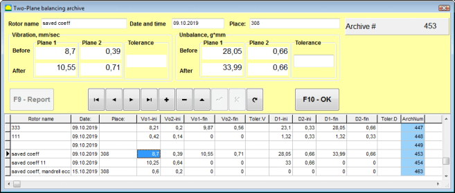
Fig. 7.32 Two plane balancing archive window.
في هذه النافذة، عليك إدخال بيانات الدوار المتوازن. بعد الضغط على ""F10-موافق"بالضغط على زر " "، ستظهر نافذة موازنة.
Balancing settings (2-plane)
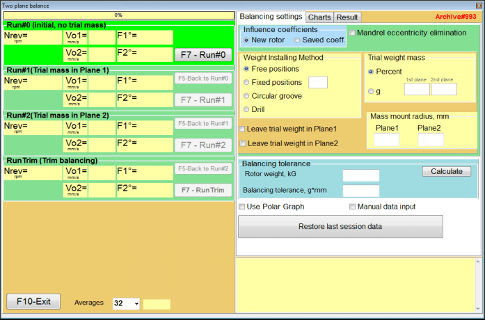
Fig. 7.33. Balancing in two planes window.
على الجانب الأيمن من النافذة يوجد ""إعدادات التوازن"علامة تبويب لإدخال الإعدادات قبل الموازنة.
- معاملات التأثير - موازنة دوار جديد أو الموازنة باستخدام معاملات التأثير المخزنة (معاملات الموازنة)
- Mandrel eccentricity elimination - الموازنة مع بداية إضافية للتخلص من تأثير لا مركزية المندريل
- طريقة ربط الوزن - تركيب أوزان تصحيحية في أي مكان على محيط الدوار أو في موضع ثابت. حسابات الحفر عند إزالة الكتلة.
- "موقف مجاني""- يمكن تركيب الأوزان في أوضاع زاوية عشوائية على محيط الدوار.".
- "موقف ثابت"يمكن تثبيت الأوزان في مواضع زاوية ثابتة على الدوّار، على سبيل المثال، على الشفرات أو الثقوب (مثلاً 12 ثقبًا - 30 درجة)، وما إلى ذلك. يجب إدخال عدد المواضع الثابتة في الحقل المخصص. بعد الموازنة، سيقوم البرنامج تلقائيًا بتقسيم الوزن إلى جزأين وتحديد عدد المواضع التي يجب تثبيت الأوزان عليها.
- كتلة الوزن التجريبي - الوزن التجريبي
- Leave trial weight in Plane1 / Plane2 - قم بإزالة أو ترك وزن التجربة عند إجراء عملية الموازنة.
- نصف قطر التركيب الشامل، مم - نصف قطر تركيب أوزان التجربة والتصحيح
- موازنة التسامح - إدخال أو حساب تفاوتات عدم التوازن المتبقية بوحدة غرام-ملليمتر
- استخدم الرسم البياني القطبي - استخدم الرسم البياني القطبي لعرض نتائج الموازنة
- إدخال البيانات يدويا - إدخال البيانات يدويًا لحساب أوزان الموازنة
- Restore last session data - استعادة بيانات القياس الخاصة بالجلسة الأخيرة في حالة فشل مواصلة الموازنة.
2 planes balancing. New rotor
إعداد نظام القياس (إدخال البيانات الأولية)
Input of the initial data for the New rotor balancing في ""موازنة مستويين. الإعدادات".
في هذه الحالة، في ""معاملات التأثير""القسم، حدد ""الدوار الجديد"" غرض.
علاوة على ذلك، في القسم ""كتلة الوزن التجريبي"يجب عليك تحديد وحدة قياس كتلة وزن التجربة."غرام"" أو ""نسبه مئويه".
عند اختيار وحدة القياس ""نسبه مئويه""، سيتم إجراء جميع الحسابات اللاحقة لكتلة الوزن التصحيحي كنسبة مئوية بالنسبة لكتلة الوزن التجريبي.
عند اختيار ""غرام""وحدة القياس، ستُجرى جميع الحسابات اللاحقة لكتلة الوزن التصحيحي بالجرام. ثم أدخل في النوافذ الموجودة على يمين النقش""غرام""كتلة أوزان التجربة التي سيتم تركيبها على الدوار".
⚠️ تنبيه! إذا كان من الضروري استخدام ""معامل محفوظ.""في وضع العمل الإضافي أثناء الموازنة الأولية، يجب إدخال كتلة أوزان التجربة في جرامات.
ثم اختر ""طريقة ربط الوزن" - "Circum"" أو ""موقف ثابت".
إذا اخترت ""موقف ثابت"يجب عليك إدخال عدد المواضع.
Calculation of tolerance for residual imbalance (Balancing tolerance)
يمكن حساب تفاوت الاختلال المتبقي (تفاوت التوازن) وفقًا للإجراء الموضح في معيار ISO 1940 "الاهتزاز". متطلبات جودة التوازن للدوارات في حالة ثابتة (صلبة). الجزء 1. تحديد تفاوتات التوازن والتحقق منها.

Fig. 7.34. Balancing tolerance calculation window
Initial run (Run#0)
عند تحقيق التوازن في مستويين في ""الدوار الجديد""الوضع، يتطلب التوازن ثلاث عمليات معايرة وتشغيل اختبار واحد على الأقل لجهاز الموازنة.
يتم إجراء قياس الاهتزاز عند بدء تشغيل الآلة لأول مرة في ""Two plane balance"نافذة العمل في"Run#0"" قسم.
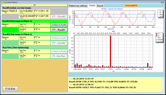
الشكل 7.35. نتائج القياس عند التوازن في مستويين بعد التشغيل الأولي.
⚠️ تنبيه! قبل البدء في عملية القياس، من الضروري تشغيل دوران دوار آلة الموازنة (التشغيل الأول) والتأكد من دخولها إلى وضع التشغيل بسرعة ثابتة.
To measure vibration parameters in the Run#0 القسم، انقر على ""F7 - Run#0"زر " (أو اضغط على مفتاح F7 على لوحة مفاتيح الكمبيوتر)
تظهر نتائج قياس سرعة الدوار (RPM) وقيمة RMS (VО1، VО2) والمراحل (F1، F2) للاهتزاز 1x في النوافذ المقابلة لـ Run#0 section.
Run#1.Trial mass in Plane1
قبل البدء في قياس معلمات الاهتزاز في ""Run#1.Trial mass in Plane1"في قسم "القسم"، يجب إيقاف دوران دوار آلة الموازنة وتركيب وزن تجريبي عليه، الكتلة المختارة في ""كتلة الوزن التجريبي"" قسم.
⚠️ تنبيه!
- تتم مناقشة مسألة اختيار كتلة الأوزان التجريبية وأماكن تثبيتها على دوار آلة الموازنة بالتفصيل في الملحق 1.
- إذا كان من الضروري استخدام معامل محفوظ. Mode in future work, the place for installing the trial weight must necessarily coincide with the place for installing the mark used to read the phase angle.
After this, it is necessary to turn on the rotation of the rotor of the balancing machine again and make sure that it has entered the operating mode.
لقياس معلمات الاهتزاز في ""Run # 1.Trial mass in Plane1"انقر على "القسم"."F7 – Run#1"زر " (أو اضغط على مفتاح F7 على لوحة مفاتيح الكمبيوتر).
عند إكمال عملية القياس بنجاح، سيتم إرجاعك إلى علامة التبويب الخاصة بنتائج القياس.
في هذه الحالة، في النوافذ المقابلة لـ ""Run#1. Trial mass in Plane1"القسم "، نتائج قياس سرعة الدوران (RPM)، بالإضافة إلى قيمة مكونات RMS (Vо1، Vо2) والمراحل (F1، F2) للاهتزاز 1x.
""تشغيل # 2. كتلة التجربة في المستوى 2""
قبل البدء في قياس معلمات الاهتزاز في القسم ""Run # 2.Trial mass in Plane2"، يجب عليك القيام بالخطوات التالية:
- إيقاف دوران دوار آلة الموازنة؛
- إزالة وزن الاختبار المثبت في المستوى 1؛
- قم بتركيب وزن تجريبي في المستوى 2، الكتلة المحددة في القسم ""كتلة الوزن التجريبي".
After this, turn on the rotation of the rotor of the balancing machine and make sure that it has entered the operating speed.
للبدء في قياس الاهتزاز في ""Run # 2.Trial mass in Plane2"انقر على "القسم"."F7 – Run # 2"زر "" (أو اضغط على مفتاح F7 على لوحة مفاتيح الكمبيوتر). ثم ""نتيجة""يفتح التبويب.".
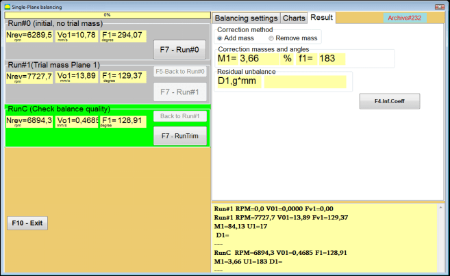
In the case of using the طريقة ربط الوزن" - "Free positions، يعرض العرض قيم الكتلة (M1، M2) وزوايا التثبيت (f1، f2) للأوزان التصحيحية.
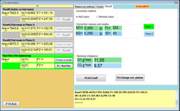
Fig. 7.36. Results of calculation of corrective weights – free position
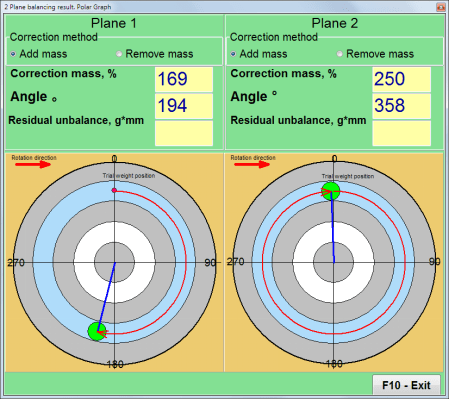
الشكل ٧.٣٧. نتائج حساب الأوزان التصحيحية - الوضع الحر. مخطط قطبي
In the case of using the Weight Attachment Method" – "مواقف ثابتة

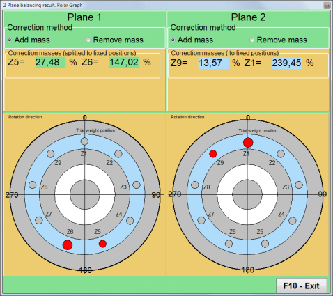
الشكل 7.38. نتائج حساب الأوزان التصحيحية - الوضع الثابت.
الشكل ٧.٣٩. نتائج حساب الأوزان التصحيحية - وضع ثابت. مخطط قطبي.
في حالة استخدام طريقة ربط الأوزان" – ""أخدود دائري"
الشكل 7.40. نتائج حساب الأوزان التصحيحية - الأخدود الدائري.
⚠️ تنبيه!
- بعد الانتهاء من عملية القياس على RUN#2 of the balancing machine, stop the rotation of the rotor and remove the trial weight previously installed. Then you can to install (or remove) corrective weights.
- يتم حساب الموضع الزاوي للأوزان التصحيحية في نظام الإحداثيات القطبية من مكان تركيب الوزن التجريبي في اتجاه دوران الدوار.
- في حالة ""موقف ثابت"- الأولشارع الموضع (Z1) يتزامن مع مكان تركيب الوزن التجريبي. اتجاه العد لرقم الموضع هو في اتجاه دوران الدوار.
- بشكل افتراضي، ستتم إضافة الوزن التصحيحي إلى الدوار. ويُشار إلى ذلك بواسطة الملصق المحدد في ""يضيف""الحقل. إذا قمت بإزالة الوزن (على سبيل المثال، عن طريق الحفر)، فيجب عليك وضع علامة في ""يمسح""الحقل، وبعد ذلك سيتغير الوضع الزاوي لوزن التصحيح تلقائيًا بمقدار 180 درجة.
RunC (Trim run)
After installing the correction weight on the balancing rotor it is necessary to carry out a RunC (trim) and evaluate the effectiveness of the performed balancing.
⚠️ تنبيه! قبل البدء في عملية القياس أثناء التشغيل التجريبي، من الضروري تشغيل دوران دوار الماكينة والتأكد من دخوله إلى سرعة التشغيل.
لقياس معلمات الاهتزاز في قسم RunTrim (التحقق من جودة التوازن)، انقر على ""F7 - رنتريم"زر " (أو اضغط على مفتاح F7 على لوحة مفاتيح الكمبيوتر).
The results of measuring the rotor rotation frequency (RPM), as well as the value of the RMS component (Vо1) and phase (F1) of 1x vibration will be shown.
ال ""نتيجة"تظهر علامة التبويب "" على الجانب الأيمن من نافذة العمل مع جدول نتائج القياس، والذي يعرض نتائج حساب معلمات الأوزان التصحيحية الإضافية.
These weights can be added to corrective weights that are already installed on the rotor to compensate for residual imbalance.
In addition, the residual rotor unbalance achieved after balancing is displayed in the lower part of this window.
في حالة أن قيم الاهتزاز المتبقي و/أو عدم التوازن المتبقي للدوار المتوازن تلبي متطلبات التسامح المنصوص عليها في الوثائق الفنية، يمكن إكمال عملية الموازنة.
وإلا فإن عملية التوازن قد تستمر. يتيح ذلك لطريقة التقريبات المتعاقبة تصحيح الأخطاء المحتملة التي قد تحدث أثناء تركيب (إزالة) الوزن التصحيحي على الدوار المتوازن.
عند مواصلة عملية الموازنة على دوار الموازنة، من الضروري تركيب (إزالة) كتلة تصحيحية إضافية، يتم توضيح معاييرها في نافذة "النتيجة".
في ""نتيجة""في النافذة، يوجد زران للتحكم يمكن استخدامهما - ""F4-Inf.Coeff", "F5 – Change correction planes".
Influence coefficients (2 planes)
ال ""F4-Inf.Coeff"يتم استخدام الزر " (أو مفتاح الوظيفة F4 على لوحة مفاتيح الكمبيوتر) لعرض وحفظ معاملات موازنة الدوار في ذاكرة الكمبيوتر، والتي تم حسابها من نتائج بدء المعايرة مرتين.
عند الضغط عليه، ""Influence coefficients (two planes)"تظهر نافذة العمل على شاشة الكمبيوتر، والتي يتم فيها عرض معاملات الموازنة المحسوبة بناءً على نتائج عمليات بدء المعايرة الثلاث الأولى.

Fig. 7.41. Working window with balancing coefficients in 2 planes.
في المستقبل، عند موازنة هذا النوع من الآلات، من المفترض أن يتطلب الأمر استخدام ""معامل محفوظ.""معاملات الوضع والتوازن المخزنة في ذاكرة الكمبيوتر.".
لحفظ المعاملات، انقر فوق ""F9 – Save"انقر على الزر وانتقل إلى"Influence coefficients archive (2planes)""النوافذ (انظر الشكل 7.42)
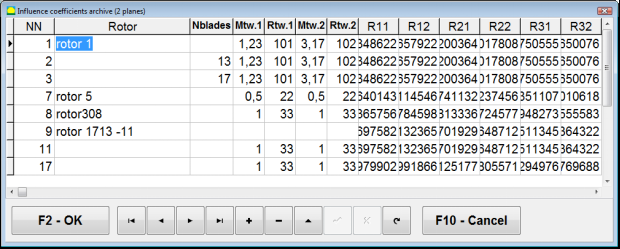
Fig. 7.42. The second page of the working window with balancing coefficients in 2 planes.
Change correction planes
ال ""F5 – Change correction planes"يتم استخدام الزر "" عند الحاجة إلى تغيير موضع مستويات التصحيح، وعندما يكون من الضروري إعادة حساب الكتل وزوايا التركيب والأوزان التصحيحية.
This mode is primarily useful when balancing rotors of complex shape (for example, crankshafts).
عند الضغط على هذا الزر، ستظهر نافذة العمل ""Recalculation of correction weights mass and angle to other correction planes"يتم عرض " على شاشة الكمبيوتر".
In this working window, you should select one of the 4 possible options by clicking corresponding picture.
تم تمييز مستويات التصحيح الأصلية (Н1 وН2) باللون الأخضر، والجديدة (K1 وK2)، والتي تحكي عنهما، باللون الأحمر.
ثم في ""Calculation data"في قسم "البيانات المطلوبة"، أدخل البيانات المطلوبة، بما في ذلك:
- المسافة بين مستويات التصحيح المقابلة (أ، ب، ج)؛
- القيم الجديدة لنصف قطر تركيب الأوزان التصحيحية على الدوار (R1 '، R2').
بعد إدخال البيانات، يجب عليك الضغط على الزر ""F9-calculate"
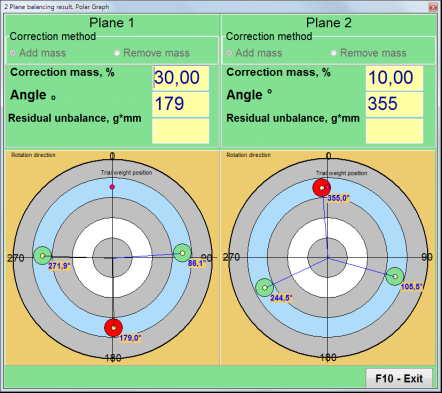
يتم عرض نتائج الحساب (الكتل M1، M2 وزوايا التثبيت للأوزان التصحيحية f1، f2) في القسم المقابل من نافذة العمل هذه.
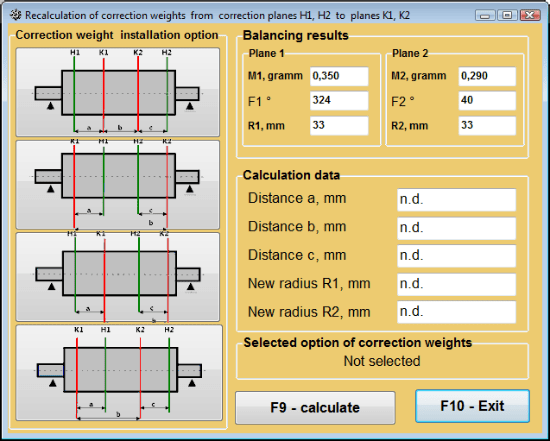
الشكل 7.43: تغيير مستويات التصحيح. إعادة حساب كتلة التصحيح وزاويته بالنسبة لمستويات تصحيح أخرى.
تم حفظ معامل التوازن في مستويين
معامل محفوظ. موازنة can be performed on a machine for which balancing coefficients have already been determined and saved in the computer memory.
⚠️ تنبيه! When re-balancing, the vibration sensors and the phase angle sensor must be installed in the same way as during the initial balancing.
يبدأ إدخال البيانات الأولية لإعادة التوازن في ""موازنة مستويين. إعدادات الموازنة".
في هذه الحالة، في ""معاملات التأثير""القسم، حدد ""معامل محفوظ.""العنصر. في هذه الحالة، النافذة""Influence coefficients archive (2planes)"ستظهر "، حيث يتم تخزين أرشيف معاملات التوازن المحددة مسبقًا.
باستخدام زري التحكم "►" أو "◄" للتنقل بين صفحات هذا الأرشيف، يمكنك تحديد السجل المطلوب الذي يحتوي على معاملات موازنة الجهاز الذي يهمنا. بعد ذلك، لاستخدام هذه البيانات في القياسات الحالية، اضغط على ""F2 – OK"انقر على الزر "" ثم ارجع إلى نافذة العمل السابقة.
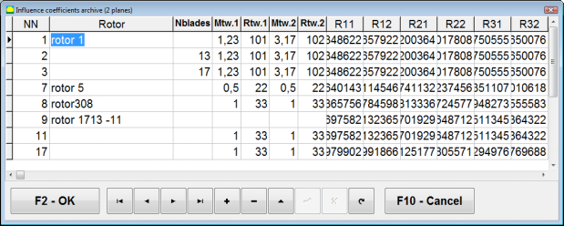
Fig. 7.44. The second page of the working window with balancing coefficients in 2 planes.
بعد ذلك، محتويات جميع النوافذ الأخرى من ""الموازنة في ٢ بلوك. بيانات المصدر"يتم ملء الحقل تلقائيًا.
Saved coeff. Balancing
"معامل محفوظ.""لا يتطلب التوازن سوى بدء ضبط واحد وبدء اختبار واحد على الأقل لآلة التوازن.".
Vibration measurement at the tuning start (تشغيل # 0يتم تنفيذ ) الآلة في ""Balancing in 2 planes"نافذة عمل تحتوي على جدول بنتائج الموازنة في تشغيل # 0 section.
⚠️ تنبيه! Before starting the measurement, it is necessary to turn on the rotation of the rotor of the balancing machine and make sure that it has entered the operating mode with a stable speed.
To measure vibration parameters in the تشغيل # 0 القسم، انقر فوق ""F7 - Run#0"زر " (أو اضغط على مفتاح F7 على لوحة مفاتيح الكمبيوتر).
The results of measuring the rotor speed (RPM), as well as the value of the components of the RMS (VО1, VО2) and phases (F1, F2) of the 1x vibration appear in the corresponding fields of the تشغيل # 0 section.
وفي الوقت نفسه، فإن ""نتيجة"" يتم فتح علامة التبويب، والتي تعرض نتائج حساب معلمات الأوزان التصحيحية التي يجب تركيبها على الدوار لتعويض عدم توازنه.
علاوة على ذلك، في حالة استخدام نظام الإحداثيات القطبية، تعرض الشاشة قيم الكتلة وزوايا التثبيت للأوزان التصحيحية.
In the case of decomposition of corrective weights on the blades, the numbers of the blades of the balancing rotor and the mass of weight that need to be installed on them are displayed.
Further, the balancing process is carried out in accordance with the recommendations set out in section 7.6.1.2. for primary balancing.
⚠️ تنبيه!
- After completion of the measurement process after the second start of the balanced machine stop the rotation of its rotor and remove the previously set trial weight. Only then you can begin to install (or remove) correction weight on the rotor.
- Counting the angular position of the place of adding (or removing) of the correction weight from the rotor is carried out on the installation site of trial weight in the polar coordinate system. Counting direction coincides with the direction of the angle of rotor rotation.
- في حالة موازنة الشفرات، تتطابق شفرة الدوار المتوازنة، والمُشار إليها بالموضع ١، مع موقع تركيب وزن الاختبار. يُضبط اتجاه الشفرة (رقم المرجع) المعروض على شاشة الكمبيوتر في اتجاه دوران الدوار.
- في هذا الإصدار من البرنامج، يُفترض افتراضيًا إضافة وزن تصحيحي إلى الدوّار. ويؤكد ذلك الوسم المُحدد في حقل "إضافة". في حال تصحيح عدم التوازن بإزالة وزن (مثلاً عن طريق الحفر)، يجب تحديد وسم في حقل "إزالة"، وعندها سيتغير الوضع الزاوي للوزن التصحيحي تلقائيًا بمقدار 180 درجة.
إزالة اللامركزية في المندريل (موازنة المؤشر) - مستويان
إذا تم تثبيت الدوار في شياق أسطواني أثناء الموازنة، فإن انحراف الشياق قد يؤدي إلى حدوث خطأ إضافي. للتخلص من هذا الخطأ، يجب نشر الدوار في الشياق بمقدار 180 درجة وتنفيذ بداية إضافية. وهذا ما يسمى موازنة الفهرس.
لتنفيذ موازنة الفهرس، يتم توفير خيار خاص في برنامج Balanset-1A. عند تحديد إزالة انحراف مغزل الشياق، يظهر قسم RunEcc إضافي في نافذة الموازنة.
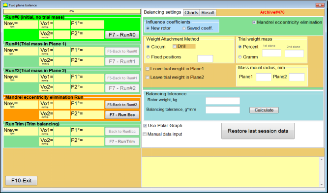
Fig. 7.45. The working window for Index balancing.
After running Run # 2 (Trial mass Plane 2), a window will appear
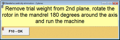
Fig. 7.46. Attention windows
بعد تثبيت الدوار بزاوية ١٨٠ درجة، يجب إكمال تشغيل برنامج Run Ecc. سيحسب البرنامج تلقائيًا اختلال التوازن الحقيقي للدوار دون التأثير على مركزية محور الدوران.
7.6 وضع الرسوم البيانية
يبدأ العمل في وضع "الرسوم البيانية" من النافذة الأولية (انظر الشكل 7.1) بالضغط على ""F8 - الرسوم البيانية". ثم تفتح نافذة "قياس الاهتزاز على قناتين. الرسوم البيانية" (انظر الشكل 7.19).

الشكل 7.47. نافذة التشغيل "قياس الاهتزاز على قناتين. الرسوم البيانية".
While working in this mode it is possible to plot four versions of vibration chart.
The first version allows to get a timeline function of the overall vibration (of vibration velocity) on the first and second measuring channels.
The second version allows you to get graphs of vibration (of vibration velocity), which occurs on rotation frequency and its higher harmonical components.
These graphs are obtained as a result of the synchronous filtering of the overall vibration time function.
The third version provides vibration charts with the results of the harmonical analysis.
The fourth version allows to get a vibration chart with the results of the spectrum analysis.
مخططات الاهتزاز العام
لرسم مخطط الاهتزاز الكلي في نافذة التشغيل ""Measurement of vibration on two channels. Charts""من الضروري تحديد وضع التشغيل""overall vibration"انقر فوق الزر المناسب. ثم اضبط قياس الاهتزاز في مربع "المدة، بالثواني"، بالنقر فوق الزر "▼" وحدد من القائمة المنسدلة المدة المطلوبة لعملية القياس، والتي قد تساوي 1 أو 5 أو 10 أو 15 أو 20 ثانية؛;
عند الاستعداد، اضغط (انقر) على ""F9عند الضغط على زر "قياس"، تبدأ عملية قياس الاهتزاز في وقت واحد على قناتين.
After completion of the measurement process in the operating window appear charts of time function of the overall vibration of the first (red) and the second (green) channels (see. Fig. 7.47).
On these charts time is plotted on X-axis and the amplitude of the vibration velocity (mm/sec) is plotted on Y-axis.
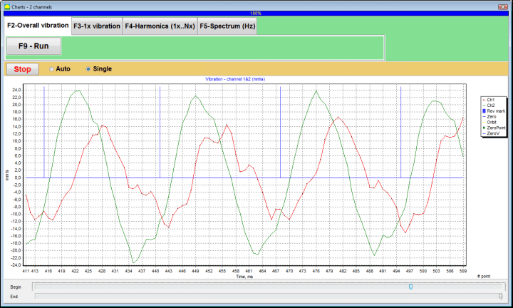
الشكل 7.48. نافذة التشغيل لمخرجات دالة الوقت لمخططات الاهتزاز الإجمالية
There are also marks (blue-colored) in these graphs connecting charts of overall vibration with the rotation frequency of the rotor. In addition, each mark indicates beginning (end) of the next revolution of the rotor.
In need of the scale change of the chart on X-axis the slider, pointed by an arrow on fig. 7.20, can be used.
مخططات اهتزاز 1x
لرسم مخطط اهتزاز 1x في نافذة التشغيل ""Measurement of vibration on two channels. Charts""من الضروري تحديد وضع التشغيل""1x vibration""بالنقر على الزر المناسب".
ثم تظهر نافذة التشغيل "اهتزاز 1x".
اضغط (انقر) على ""F9عند الضغط على زر "قياس"، تبدأ عملية قياس الاهتزاز في وقت واحد على قناتين.
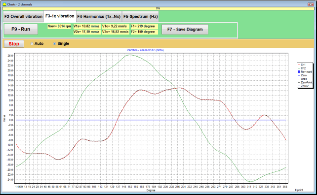
الشكل 7.49. نافذة تشغيل لمخرجات مخططات الاهتزاز 1x.
After completion of the measurement process and mathematical calculation of results (synchronous filtering of the time function of the overall vibration) on display in the main window on a period equal to one revolution of the rotor appear charts of the 1x vibration on two channels.
In this case, a chart for the first channel is depicted in red and for the second channel in green. On these charts angle of the rotor revolution is plotted (from mark to mark) on X-axis and the amplitude of the vibration velocity (mm/sec) is plotted on Y-axis.
بالإضافة إلى ذلك، في الجزء العلوي من نافذة العمل (إلى يمين الزر ""F9 – القياس"") القيم العددية لقياسات الاهتزاز لكلا القناتين، على غرار تلك التي نحصل عليها في ""Vibration meter"يتم عرض "الوضع".
In particular: RMS value of the overall vibration (V1s, V2s), the magnitude of RMS (V1o, V2o) and phase (Fi, Fj) of the 1x vibration and rotor speed (Nrev).
مخططات الاهتزاز مع نتائج التحليل التوافقي
لرسم مخطط بياني بنتائج التحليل التوافقي في نافذة التشغيل ""Measurement of vibration on two channels. Charts""من الضروري تحديد وضع التشغيل""Harmonical analysis""بالنقر على الزر المناسب".
ثم تظهر نافذة تشغيلية لإخراج متزامن لمخططات الوظيفة المؤقتة وطيف الجوانب التوافقية الاهتزازية التي تكون فترتها مساوية أو مضاعفة لتردد دوران الدوار.
انتباه!
When operating in this mode it is necessary to use the phase angle sensor which synchronizes the measurement process with the rotor frequency of the machines to which the sensor is set.
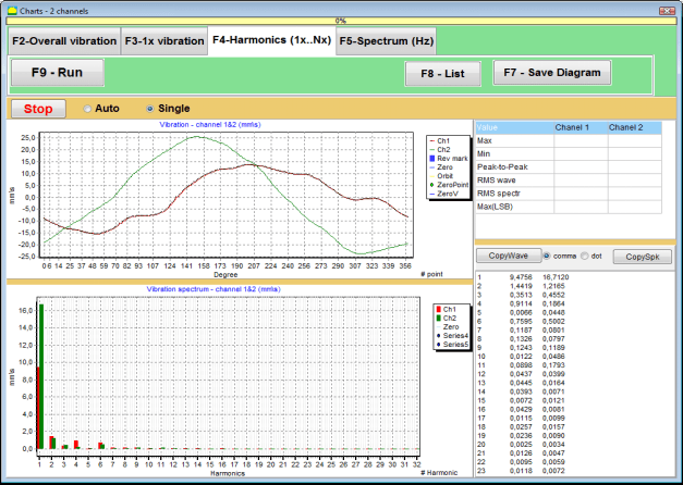
الشكل 7.50. توافقيات نافذة التشغيل للاهتزاز 1x.
عند الاستعداد، اضغط (انقر) على ""F9عند الضغط على زر "قياس"، تبدأ عملية قياس الاهتزاز في وقت واحد على قناتين.
بعد اكتمال عملية القياس، تظهر في نافذة التشغيل مخططات دالة الوقت (المخطط الأعلى) والتوافقيات للاهتزاز 1x (المخطط السفلي).
The number of harmonic components is plotted on X-axis and RMS of the vibration velocity (mm/sec) is plotted on Y-axis.
مخططات مجال زمن الاهتزاز والطيف
لرسم مخطط الطيف، استخدم ""طيف F5"" فاتورة غير مدفوعة:
ثم تظهر نافذة تشغيلية لإخراج مخططات الموجة وطيف الاهتزاز في وقت واحد.

الشكل 7.51. نافذة التشغيل لإخراج طيف الاهتزاز.
عند الاستعداد، اضغط (انقر) على ""F9عند الضغط على زر "قياس"، تبدأ عملية قياس الاهتزاز في وقت واحد على قناتين.
بعد اكتمال عملية القياس، تظهر في نافذة التشغيل مخططات دالة الوقت (المخطط الأعلى) وطيف الاهتزاز (المخطط السفلي).
The vibration frequency is plotted on X-axis and RMS of the vibration velocity (mm/sec) is plotted on Y-axis.
In this case, a chart for the first channel is depicted in red and for the second channel in green.
8. تعليمات عامة حول تشغيل الجهاز وصيانته
8.1 موازنة معايير الجودة (معيار ISO 2372)
يمكن تقييم جودة الموازنة باستخدام مستويات الاهتزاز المحددة وفقًا لمعيار ISO 2372. يوضح الجدول أدناه مستويات الاهتزاز المقبولة لمختلف فئات الآلات:
| فئة الآلة | Good (مم/ثانية جذر متوسط التربيع) |
مقبول (مم/ثانية جذر متوسط التربيع) |
لا يزال مقبولا (مم/ثانية جذر متوسط التربيع) |
غير مقبول (مم/ثانية جذر متوسط التربيع) |
|---|---|---|---|---|
| الصف الأول آلات صغيرة على أسس صلبة (محركات تصل إلى 15 كيلو واط) |
< 0.7 | 0.7 - 1.8 | 1.8 - 4.5 | > 4.5 |
| الصف الثاني آلات متوسطة الحجم بدون أسس (محركات 15-75 كيلو وات)، آليات دفع تصل إلى 300 كيلو وات |
< 1.1 | 1.1 - 2.8 | 2.8 - 7.1 | > 7.1 |
| الصف الثالث آلات كبيرة على أسس صلبة (المعدات التي تزيد عن 300 كيلو وات) |
< 1.8 | 1.8 - 4.5 | 4.5 - 11 | > 11 |
| الصف الرابع آلات كبيرة على أسس خفيفة الوزن (المعدات التي تزيد عن 300 كيلو وات) |
< 2.8 | 2.8 - 7.1 | 7.1 - 18 | > 18 |
ملاحظة: تُقدّم هذه القيم إرشاداتٍ لتقييم جودة الموازنة. يُرجى دائمًا مراجعة مواصفات الشركة المُصنّعة للمعدات والمعايير المُطبقة لتطبيقك.
8.2 متطلبات الصيانة
🔧 الصيانة الدورية
- ✓معايرة منتظمة لأجهزة الاستشعار وفقًا لمواصفات الشركة المصنعة
- ✓حافظ على أجهزة الاستشعار نظيفة وخالية من الحطام المغناطيسي
- ✓قم بتخزين المعدات في حقيبة واقية عندما لا تكون قيد الاستخدام
- ✓حماية مستشعر الليزر من الغبار والرطوبة
- ✓تحقق من توصيلات الكابلات بانتظام بحثًا عن التآكل أو التلف
- ✓تحديث البرنامج حسب توصية الشركة المصنعة
- ✓احتفظ بنسخ احتياطية من بيانات الموازنة المهمة
📋 معايير الصيانة في الاتحاد الأوروبي
يجب أن تتوافق صيانة المعدات مع:
- EN ISO 9001: متطلبات أنظمة إدارة الجودة
- EN 13306: مصطلحات وتعريفات الصيانة
- EN 15341: مؤشرات الأداء الرئيسية للصيانة
- عمليات تفتيش السلامة المنتظمة وفقًا لتوجيه الآلات في الاتحاد الأوروبي
الملحق 1. موازنة الدوار
الدوّار هو جسم يدور حول محور معين، ويُثبّت بواسطة أسطح ارتكازه في الدعامات. تنقل أسطح ارتكاز الدوّار الأوزان إلى الدعامات عبر محامل دحرجة أو انزلاقية. عند استخدام مصطلح "سطح الارتكاز"، فإننا نشير ببساطة إلى المحور* أو الأسطح التي تحل محل المحور.
*Journal (Zapfen باللغة الألمانية تعني "journal" أو "pin") - هو جزء من عمود أو محور، يتم حمله بواسطة حامل (صندوق المحمل).
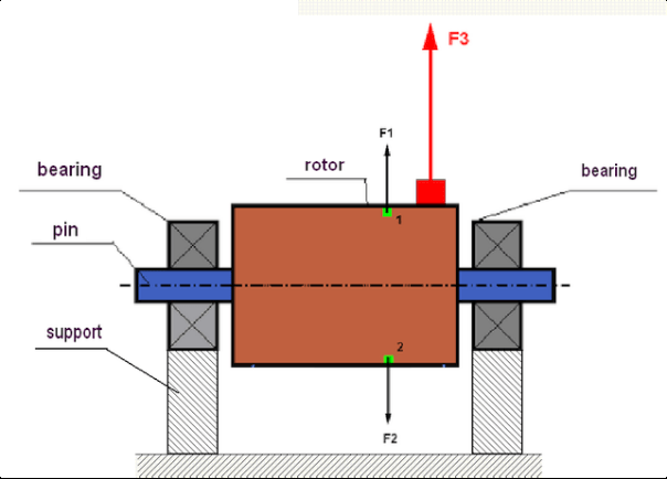
fig.1 Rotor and centrifugal forces.
In a perfectly balanced rotor, its mass is distributed symmetrically regarding the axis of the rotation. This means that any element of the rotor can correspond to another element located symmetrically in a relation to the axis of the rotation. During rotation, each rotor element acts upon by a centrifugal force directed in the radial direction (perpendicular to the axis of the rotor rotation). In a balanced rotor, the centrifugal force influencing any element of the rotor is balanced by the centrifugal force that influences the symmetrical element. For example, elements 1 and 2 (shown in fig.1 and colored in green) are influenced by centrifugal forces F1 and F2: equal in value and absolutely opposite in directions. This is true for all symmetrical elements of the rotor and thus the total centrifugal force influencing the rotor is equal to 0 the rotor is balanced. But if the symmetry of the rotor is broken (in Figure 1, the asymmetric element is marked in red), then the unbalanced centrifugal force F3 begins to act on the rotor.
عند الدوران، يتغير اتجاه هذه القوة مع دوران الدوار. ينتقل الحمل الديناميكي الناتج عن هذه القوة إلى المحامل، مما يؤدي إلى تآكلها المتسارع. بالإضافة إلى ذلك، وتحت تأثير هذه القوة المتغيرة، يحدث تشوه دوري للدعامات والأساس الذي يُثبّت عليه الدوار، مما يُنتج اهتزازًا. ولإزالة اختلال توازن الدوار والاهتزاز المصاحب له، من الضروري وضع كتل موازنة لاستعادة تناسق الدوار.
Rotor balancing is an operation to eliminate imbalance by adding balancing masses.
The task of balancing is to find the value and places (angle) of the installation of one or more balancing masses.
أنواع الدوارات وعدم التوازن
Considering the strength of the rotor material and the magnitude of the centrifugal forces influencing it, the rotors can be divided into two types: rigid and flexible.
قد تتشوه الدوارات الصلبة قليلاً في ظروف التشغيل تحت تأثير القوة الطاردة المركزية، ولكن قد يتم إهمال تأثير هذا التشوه في الحسابات.
Deformation of flexible rotors on the other hand should never be neglected. The deformation of flexible rotors complicates the solution for the balancing problem and requires the use of some other mathematical models in comparison with the task of balancing rigid rotors. It is important to mention that the same rotor at low speeds of rotation can behave like rigid one and at high speeds it will behave like flexible one. Further on we will consider the balancing of rigid rotors only.
بناءً على توزيع الكتل غير المتوازنة على طول الدوار، يُمكن التمييز بين نوعين من عدم التوازن: ثابت وديناميكي. وينطبق الأمر نفسه على موازنة الدوار الثابت والديناميكي.
يحدث عدم التوازن الساكن للدوار دون دورانه. بعبارة أخرى، يكون الدوار ساكنًا عندما يكون تحت تأثير الجاذبية، بالإضافة إلى أنه يُدير "النقطة الثقيلة" إلى الأسفل. يوضح الشكل 2 مثالًا على دوار ذي عدم توازن ساكن.

Fig.2
The dynamic imbalance occurs only when the rotor spins.
An example of a rotor with the dynamic imbalance is presented in Fig.3.
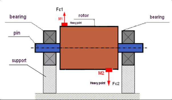
Fig.3. Dynamic imbalance of rotor – couple of the centrifugal forces
في هذه الحالة، تقع الكتلتان المتساويتان غير المتوازنتين M1 وM2 على سطحين مختلفين - في مواقع مختلفة على طول الدوار. في الوضع الساكن، أي عندما لا يدور الدوار، قد يتأثر الدوار فقط بالجاذبية، وبالتالي تتوازن الكتلتان. أما في الوضع الديناميكي، عندما يدور الدوار، تبدأ الكتلتان M1 وM2 بالتأثر بقوتين طاردتين مركزيتين FЎ1 وFЎ2. هاتان القوتان متساويتان في القيمة ومتعاكستان في الاتجاه. ومع ذلك، نظرًا لوجودهما في مواقع مختلفة على طول العمود وليسا على نفس الخط، فإن القوتين لا تعوضان بعضهما البعض. تُحدث القوتان FЎ1 وFЎ2 عزمًا يؤثر على الدوار. ولهذا يُطلق على هذا الاختلال اسم "العزمي". وبناءً على ذلك، تؤثر قوى الطرد المركزي غير المتوازنة على دعامات المحامل، والتي قد تتجاوز بشكل كبير القوى التي اعتمدنا عليها، كما أنها تُقلل من عمر خدمة المحامل.
بما أن هذا النوع من عدم التوازن لا يحدث إلا في الحركة الديناميكية أثناء دوران الدوار، فإنه يُسمى ديناميكيًا. ولا يمكن التخلص منه بالموازنة الساكنة (أو ما يُسمى "على الشفرات") أو بأي طريقة مشابهة. وللتخلص من عدم التوازن الديناميكي، من الضروري وضع وزنين مُعاكسين يُولِّدان عزمًا مساويًا في القيمة ومعاكسًا في الاتجاه للعزم الناتج عن الكتلتين M1 وM2. ليس من الضروري أن تُركَّب الكتل المُعاكسة في الجهة المقابلة للكتلتين M1 وM2 أو أن تكون مساوية لهما في القيمة. الأهم هو أن تُولِّد عزمًا يُعاكس تمامًا لحظة حدوث عدم التوازن.
بشكل عام، قد لا تتساوى الكتلتان M1 وM2، مما يؤدي إلى مزيج من عدم التوازن الساكن والديناميكي. وقد ثبت نظريًا أنه للتخلص من عدم التوازن في الدوار الصلب، يكفي تركيب وزنين متباعدين على طوله. يعوض هذان الوزنان كلاً من العزم الناتج عن عدم التوازن الديناميكي وقوة الطرد المركزي الناتجة عن عدم تناظر الكتلة بالنسبة لمحور الدوار (عدم التوازن الساكن). وكما هو معتاد، يكون عدم التوازن الديناميكي شائعًا في الدوارات الطويلة، مثل الأعمدة، بينما يكون ثابتًا في الدوارات الضيقة. مع ذلك، إذا تم تركيب الدوار الضيق بشكل مائل بالنسبة للمحور، أو ما هو أسوأ، مشوهًا (ما يُعرف بـ"تذبذب العجلة")، فسيكون من الصعب التخلص من عدم التوازن الديناميكي (انظر الشكل 4)، نظرًا لصعوبة ضبط أوزان التصحيح التي تُحدث عزم التعويض المناسب.
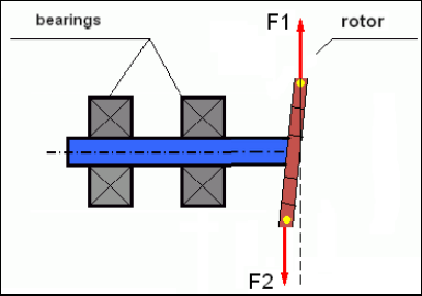
Fig.4 Dynamic balancing of the wobbling wheel
نظراً لأن كتف الدوّار الضيق يُولّد عزماً قصيراً، فقد يتطلب الأمر استخدام أوزان تصحيحية ذات كتلة كبيرة. ولكن في الوقت نفسه، يوجد ما يُسمى "عدم التوازن المُستحث" المرتبط بتشوه الدوّار الضيق تحت تأثير قوى الطرد المركزي الناتجة عن الأوزان التصحيحية.
See the example:
""تعليمات منهجية حول موازنة الدوارات الصلبة"" ISO 1940-1:2003 Mechanical vibration – Balance quality requirements for rotors in a constant (rigid) state – Part 1: Specification and verification of balance tolerances
This is visible for narrow fan wheels, which, in addition to the power imbalance, also influences an aerodynamic imbalance. And it is important to bear in mind that the aerodynamic imbalance, in fact the aerodynamic force, is directly proportional to the angular velocity of the rotor, and to compensate it, the centrifugal force of the correcting mass is used, which is proportional to the square of the angular velocity. Therefore, the balancing effect may only occur at a specific balancing frequency. At other speeds there would be an additional gap. The same can be said about electromagnetic forces in an electromagnetic motor, which are also proportional to the angular velocity. In other words it is impossible to eliminate all causes of vibration of the mechanism by any means of balancing.
أساسيات الاهتزاز
الاهتزاز هو رد فعل تصميم الآلية لتأثير قوة الإثارة الدورية. قد تكون لهذه القوة طبيعة مختلفة.
- تُعدّ قوة الطرد المركزي الناتجة عن عدم توازن الدوّار قوةً غير مُعوَّضة تؤثر على "النقطة الأثقل". ويتم التخلص من هذه القوة، بالإضافة إلى الاهتزاز الناتج عنها، من خلال موازنة الدوّار.
- تنشأ قوى التفاعل، ذات الطبيعة الهندسية، نتيجةً لأخطاء في تصنيع وتركيب الأجزاء المتزاوجة. قد تحدث هذه القوى، على سبيل المثال، بسبب عدم استدارة محور الدوران، أو أخطاء في شكل أسنان التروس، أو تموج مجاري المحامل، أو عدم محاذاة الأعمدة المتزاوجة، وما إلى ذلك. في حالة عدم استدارة أعناق المحامل، سينزاح محور العمود تبعًا لزاوية دورانه. على الرغم من أن هذا الاهتزاز يظهر عند سرعة الدوران، إلا أنه يكاد يكون من المستحيل التخلص منه عن طريق الموازنة.
- Aerodynamic forces arising from the rotation of the impeller fans and other blade mechanisms. Hydrodynamic forces arising from the rotation of hydraulic pump impellers, turbines, etc.
- القوى الكهرومغناطيسية الناشئة عن تشغيل الآلات الكهربائية نتيجة، على سبيل المثال، بسبب عدم تناسق لفائف الدوار، ووجود دورات قصيرة الدائرة، وما إلى ذلك.
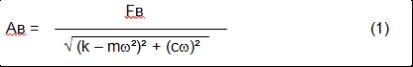
The magnitude of vibration (for example, its amplitude AB) depends not only on the magnitude of the excitation force Fт acting on the mechanism with the circular frequency ω, but also on the stiffness k of the structure of the mechanism, its mass m, and damping coefficient C.
Various types of sensors can be used to measure vibration and balance mechanisms, including:
- absolute vibration sensors designed to measure vibration acceleration (accelerometers) and vibration velocity sensors;
- أجهزة استشعار الاهتزاز النسبي ذات التيار الدوامي أو السعوي، مصممة لقياس الاهتزاز.
In some cases (when the structure of the mechanism allows it) sensors of force can also be used to examine its vibration weight.
Particularly, they are widely used to measure the vibration weight of the supports of hardbearing balancing machines.
Therefore vibration is the reaction of the mechanism to the influence of external forces. The amount of vibration depends not only on the magnitude of the force acting on the mechanism, but also on the rigidity of the mechanism. Two forces with the same magnitude can lead to different vibrations. In mechanisms with a rigid support structure, even with the small vibration, the bearing units can be significantly influenced by dynamic weights. Therefore, when balancing mechanisms with stiff legs apply the force sensors, and vibration (vibro accelerometers). Vibration sensors are only used on mechanisms with relatively pliable supports, right when the action of unbalanced centrifugal forces leads to a noticeable deformation of the supports and vibration. Force sensors are used in rigid supports even when significant forces arising from imbalance do not lead to significant vibration.
رنين الهيكل
We have previously mentioned that rotors are divided into rigid and flexible. The rigidity or flexibility of the rotor should not be confused with the stiffness or mobility of the supports (foundation) on which the rotor is located. The rotor is considered rigid when its deformation (bending) under the action of centrifugal forces can be neglected. The deformation of the flexible rotor is relatively large: it cannot be neglected.
في هذه المقالة، ندرس فقط موازنة الدوارات الصلبة. يمكن وضع الدوار الصلب (غير القابل للتشوه) بدوره على دعائم صلبة أو متحركة (قابلة للطرق). من الواضح أن صلابة/حركة الدعامات نسبية وتعتمد على سرعة دوران الدوار ومقدار قوى الطرد المركزي الناتجة. الحد الاصطلاحي هو تردد التذبذبات الحرة لدعامات/أساسات الدوار. بالنسبة للأنظمة الميكانيكية، يتحدد شكل وتردد التذبذبات الحرة من خلال كتلة ومرونة عناصر النظام الميكانيكي. أي أن تردد التذبذبات الطبيعية هو سمة داخلية للنظام الميكانيكي ولا يعتمد على قوى خارجية. تميل الدعامات، عند انحرافها عن حالة التوازن، إلى العودة إلى موضع توازنها بسبب مرونتها. ولكن بسبب قصور الدوار الضخم، تكون هذه العملية من طبيعة التذبذبات المخمدة. هذه التذبذبات هي تذبذبات خاصة بنظام دعامة الدوار. يعتمد ترددها على نسبة كتلة الدوار ومرونة الدعامات.
When the rotor begins to rotate and the frequency of its rotation approaches the frequency of its own oscillations, the vibration amplitude increases sharply, which can even lead to the destruction of the structure.
There is a phenomenon of mechanical resonance. In the resonance region, a change in the speed of rotation by 100 rpm can lead to an increase in a vibration tenfold. In this case (in the resonance region) the vibration phase changes by 180°.
إذا كان تصميم الآلية رديئًا، وكانت سرعة دوران الدوّار قريبة من التردد الطبيعي للاهتزازات، يصبح تشغيل الآلية مستحيلاً بسبب الاهتزازات العالية غير المقبولة. كما تصبح طرق الموازنة القياسية غير فعّالة، إذ تتغير المعايير بشكل كبير حتى مع تغيير طفيف في سرعة الدوران. تُستخدم طرق خاصة في مجال موازنة الرنين، ولكن لم يتم شرحها بالتفصيل في هذه المقالة. يُمكن تحديد تردد الاهتزازات الطبيعية للآلية عند توقفها (عند إيقاف تشغيل الدوّار) أو عند الاصطدام، مع إجراء تحليل طيفي لاحق لاستجابة النظام للصدمة. يوفر جهاز "Balanset-1" إمكانية تحديد الترددات الطبيعية للهياكل الميكانيكية باستخدام هذه الطرق.
For mechanisms whose operating speed is higher than the resonance frequency, that is, operating in the resonant mode, supports are considered as mobile ones and vibration sensors are used to measure, mainly vibration accelerometers that measure the acceleration of structural elements. For mechanisms operating in hard bearing mode, supports are considered as rigid. In this case, force sensors are used.
النماذج الخطية وغير الخطية للنظام الميكانيكي
Mathematical models (linear) are used for calculations when balancing rigid rotors. The linearity of the model means that one model is directly proportionally (linearly) dependent on the other. For example, if the uncompensated mass on the rotor is doubled, then the vibration value will be doubled correspondingly. For rigid rotors you can use a linear model because such rotors are not deformed. It is no longer possible to use a linear model for flexible rotors. For a flexible rotor, with an increase of the mass of a heavy point during rotation, an additional deformation will occur, and in addition to the mass, the radius of the heavy point will also increase. Therefore, for a flexible rotor, the vibration will more than double, and the usual calculation methods will not work. Also, a violation of the linearity of the model can lead to a change in the elasticity of the supports at their large deformations, for example, when small deformations of the supports work some structural elements, and when large in the work include other structural elements. Therefore it is impossible to balance the mechanisms that are not fixed at the base, and, for example, are simply established on a floor. With significant vibrations, the unbalance force can detach the mechanism from the floor, thereby significantly changing the stiffness characteristics of the system. The engine legs must be securely fastened, bolted fasteners tightened, the thickness of the washers must provide sufficient rigidity, etc. With broken bearings, a significant displacement of the shaft and its impacts is possible, which will also lead to a violation of linearity and the impossibility of carrying out high-quality balancing.
Methods and devices for balancing
As mentioned above, balancing is the process of combining the main Central axis of inertia with the axis of rotation of the rotor.
The specified process can be executed in two ways.
The first method involves the processing of the rotor axles, which is performed in such a way that the axis passing through the centers of the section of the axles with the main Central axis of inertia of the rotor. This technique is rarely used in practice and will not be discussed in detail in this article.
The second (most common) method involves moving, installing or removing corrective masses on the rotor, which are placed in such a way that the axis of inertia of the rotor is as close as possible to the axis of its rotation.
Moving, adding or removing corrective masses during balancing can be done using a variety of technological operations, including: drilling, milling, surfacing, welding, screwing or unscrewing screws, burning with a laser beam or electron beam, electrolysis, electromagnetic welding, etc.
The balancing process can be performed in two ways:
- مجموعة الدوارات المتوازنة (في محاملها الخاصة)؛
- موازنة الدوارات على آلات الموازنة.
To balance the rotors in their own bearings we usually use specialized balancing devices (kits), which allows us to measure the vibration of the balanced rotor at the speed of its rotation in a vector form, i.e. to measure both the amplitude and phase of vibration.
Currently, these devices are manufactured on the basis of microprocessor technology and (in addition to the measurement and analysis of vibration) provide automated calculation of the parameters of corrective weights that must be installed on the rotor to compensate its imbalance.
These devices include:
- وحدة قياس وحساب، مصنوعة على أساس جهاز كمبيوتر أو وحدة تحكم صناعية؛
- اثنين (أو أكثر) من أجهزة استشعار الاهتزاز؛
- مستشعر زاوية الطور؛
- المعدات اللازمة لتركيب أجهزة الاستشعار في المنشأة؛
- برنامج متخصص مصمم لأداء دورة كاملة من قياس معلمات عدم توازن الدوار في مستوى واحد أو اثنين أو أكثر من مستويات التصحيح.
لموازنة الدوارات على آلات الموازنة، بالإضافة إلى جهاز موازنة متخصص (نظام قياس الآلة)، يلزم وجود "آلية فك اللفائف" مصممة لتثبيت الدوار على الدعامات وضمان دورانه بسرعة ثابتة.
Currently, the most common balancing machines exist in two types:
- مفرط الرنين (مع دعامات مرنة)؛
- محمل صلب (مع دعامات صلبة).
Over-resonant machines have a relatively pliable supports, made, for example, on the basis of the flat springs.
The natural oscillation frequency of these supports is usually 2-3 times lower than the speed of the balanced rotor, which is mounted on them.
Vibration sensors (accelerometers, vibration velocity sensors, etc.) are usually used to measure the vibration of the supports of a resonant machine.
In the hardbearing balancing machines are used relatively-rigid supports, natural oscillation frequencies of which should be 2-3 times higher than the speed of the balanced rotor.
Force sensors are usually used to measure the vibration weight on the supports of the machine.
The advantage of the hard bearing balancing machines is that they can be balanced at relatively low rotor speeds (up to 400-500 rpm), which greatly simplifies the design of the machine and its foundation, as well as increases the productivity and safety of balancing.
Balancing technique
⚠️ لا يزيل التوازن إلا الاهتزاز الناتج عن عدم تناسق توزيع كتلة الدوار بالنسبة لمحور دورانه. أما أنواع الاهتزاز الأخرى فلا يمكن التخلص منها بالتوازن!
Balancing is the subject to technically serviceable mechanisms, the design of which ensures the absence of resonances at the operating speed, securely fixed on the foundation, installed in serviceable bearings.
🚫 يجب إصلاح الآلية المعيبة، وبعد ذلك فقط تتم موازنتها. وإلا، فإن الموازنة الجيدة مستحيلة.
Balancing cannot be a substitute for repair!
The main task of balancing is to find the mass and the place (angle) of installation of compensating weights, which are balanced by centrifugal forces.
As mentioned above, for rigid rotors it is generally necessary and sufficient to install two compensating weights. This will eliminate both the static and dynamic rotor imbalance. A general scheme of the vibration measurement during balancing looks like the following:
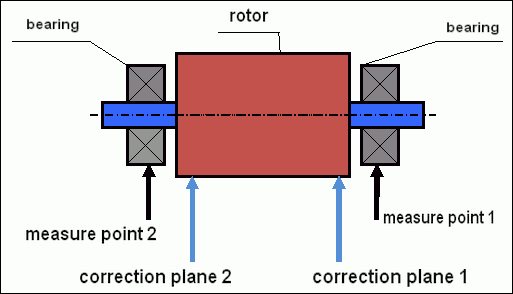
fig.5 Dynamic balancing – correction planes and measure points
Vibration sensors are installed on the bearing supports at points 1 and 2. The speed mark is fixed right on the rotor, a reflective tape is glued usually. The speed mark is used by the laser tachometer to determine the speed of the rotor and the phase of the vibration signal.
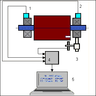
الشكل 6. تركيب المستشعرات أثناء الموازنة في مستويين، باستخدام Balanset-1
1,2-vibration sensors, 3-phase, 4- USB measuring unit, 5-laptop
In most cases, dynamic balancing is carried out by the method of three starts. This method is based on the fact that test weights of an already-known mass are installed on the rotor in series in 1 and 2 planes; so the masses and the place of installation of balancing weights are calculated based on the results of changing the vibration parameters.
يُطلق على مكان تركيب الوزن اسم مستوى التصحيح. عادةً، تُختار مستويات التصحيح في منطقة دعامات المحامل التي يُركّب عليها الدوار.
يُقاس الاهتزاز الأولي عند التشغيل الأول. ثم يُثبّت وزن تجريبي ذو كتلة معلومة على الدوار الأقرب إلى أحد الدعامات. ثم يُجرى التشغيل الثاني، ونقيس معاملات الاهتزاز التي يُتوقع أن تتغير نتيجة تركيب الوزن التجريبي. بعد ذلك، يُزال الوزن التجريبي من المستوى الأول ويُثبّت في المستوى الثاني. يُجرى التشغيل الثالث وتُقاس معاملات الاهتزاز. عند إزالة الوزن التجريبي، يحسب البرنامج تلقائيًا الكتلة وموقع (زوايا) تركيب أوزان الموازنة.
The point in setting up test weights is to determine how the system responds to the imbalance change. When we know the masses and the location of the sample weights, the program can calculate the so-called influence coefficients, showing how the introduction of a known imbalance affects the vibration parameters. The coefficients of influence are the characteristics of the mechanical system itself and depend on the stiffness of the supports and the mass (inertia) of the rotor-support system.
For the same type of mechanisms of the same design, the coefficients of influence will be similar. You can save them in your computer memory and use them afterwards for balancing the same type of mechanisms without carrying out test runs, which greatly improves the performance of the balancing. We should also note that the mass of test weights should be chosen as such so that the vibration parameters vary markedly when installing test weights. Otherwise, the error in calculating the coefficients of the affect increases and the quality of balancing deteriorates.
يُقدّم دليل جهاز Balanset-1 معادلةً تُتيح لك تحديد كتلة وزن الاختبار تقريبًا، وذلك بناءً على كتلة وسرعة دوران الدوّار المتوازن. وكما هو موضح في الشكل 1، تعمل قوة الطرد المركزي في الاتجاه القطري، أي عموديًا على محور الدوّار. لذا، يجب تركيب مستشعرات الاهتزاز بحيث يكون محور حساسيتها مُوجّهًا أيضًا في الاتجاه القطري. عادةً ما تكون صلابة الأساس في الاتجاه الأفقي أقل، وبالتالي يكون الاهتزاز في هذا الاتجاه أعلى. لذلك، ولزيادة حساسية المستشعرات، يجب تركيبها بحيث يكون محور حساسيتها مُوجّهًا أيضًا أفقيًا. على الرغم من عدم وجود فرق جوهري، فإنه بالإضافة إلى الاهتزاز في الاتجاه القطري، من الضروري التحكم في الاهتزاز في الاتجاه المحوري، على طول محور دوران الدوّار. عادةً ما ينتج هذا الاهتزاز ليس عن عدم التوازن، بل عن أسباب أخرى، أهمها عدم محاذاة الأعمدة المتصلة عبر الوصلة. لا يُزال هذا الاهتزاز بالموازنة، بل يتطلب الأمر في هذه الحالة محاذاة. عمليًا، غالبًا ما تُعاني هذه الآليات من عدم توازن في الدوّار وعدم محاذاة في الأعمدة، مما يُعقّد مهمة إزالة الاهتزاز بشكل كبير. في مثل هذه الحالات، يجب أولًا محاذاة الآلية ثم موازنتها. (مع العلم أنه في حالة وجود اختلال كبير في عزم الدوران، يحدث الاهتزاز أيضًا في الاتجاه المحوري نتيجةً لالتواء الهيكل الأساسي).
دقة القياس وتحليل الأخطاء
يُعد فهم دقة القياس أمرًا بالغ الأهمية لعمليات الموازنة الاحترافية. يوفر جهاز Balanset-1A دقة القياس التالية:
| المعلمة | صيغة الدقة | مثال (للقيم النموذجية) |
|---|---|---|
| سرعة الاهتزاز RMS | ±(0.1 + 0.1×فولتتم قياسه) مم/ثانية | لمدة 5 مم/ثانية: ±0.6 مم/ثانية لمدة 10 مم/ثانية: ±1.1 مم/ثانية |
| تردد الدوران | ±(1 + 0.005×Nتم قياسه) دورة في الدقيقة | لـ 1000 دورة في الدقيقة: ±6 دورة في الدقيقة لـ 3000 دورة في الدقيقة: ±16 دورة في الدقيقة |
| قياس الطور | ±1 درجة | دقة ثابتة عبر جميع السرعات |
⚠️ ضروري لتحقيق التوازن الدقيق
- !يجب أن يتسبب وزن الاختبار في تغيير في السعة بمقدار >20-30% و/أو >20-30 درجة تغير الطور
- !إذا كانت التغييرات أصغر، فإن أخطاء القياس تزيد بشكل كبير
- !يجب ألا يتجاوز اتساع الاهتزاز واستقرار الطور 10-15% بين القياسات
- !إذا تجاوز التباين 15%، فتحقق من ظروف الرنين أو المشكلات الميكانيكية
معايير تقييم جودة آليات الموازنة
Quality of rotor (mechanisms) balancing can be estimated in two ways. The first method involves comparing the value of the residual imbalance determined during the balancing with the tolerance for the residual imbalance. The specified tolerances for various classes of rotors installed in the standard ISO 1940-1-2007. «الاهتزاز. متطلبات جودة توازن الدوارات الصلبة. الجزء 1. تحديد عدم التوازن المسموح به".
مع ذلك، فإن تطبيق هذه التفاوتات لا يضمن تمامًا موثوقية تشغيل الآلية المرتبطة بتحقيق أدنى مستوى للاهتزاز. ويعود ذلك إلى أن اهتزاز الآلية لا يتحدد فقط بمقدار القوة المرتبطة باختلال التوازن المتبقي في دوارها، بل يعتمد أيضًا على عدد من المعايير الأخرى، بما في ذلك: صلابة العناصر الهيكلية للآلية (K)، وكتلتها (M)، ومعامل التخميد، والسرعة. لذلك، لتقييم الخصائص الديناميكية للآلية (بما في ذلك جودة توازنها)، يُنصح في بعض الحالات بتقييم مستوى الاهتزاز المتبقي للآلية، والذي يخضع لعدد من المعايير.
The most common standard regulating permissible vibration levels of mechanisms is معاينة المواصفة القياسية الدولية ISO 10816-3:2009: الاهتزاز الميكانيكي - تقييم اهتزاز الآلات عن طريق القياسات على الأجزاء غير الدوارة - الجزء 3: الآلات الصناعية ذات القدرة الاسمية التي تزيد عن 15 كيلوواط والسرعات الاسمية التي تتراوح بين 120 دورة في الدقيقة و15000 دورة في الدقيقة عند قياسها في الموقع.»
With its help, you can set the tolerance on all types of machines, taking into account the power of their electric drive.
In addition to this universal standard, there are a number of specialized standards developed for specific types of mechanisms. For example,
- ISO 14694:2003 "المراوح الصناعية - مواصفات جودة التوازن ومستويات الاهتزاز""
- ISO 7919-1-2002 "اهتزاز الآلات بدون حركة ترددية. القياسات على الأعمدة الدوارة ومعايير التقييم. إرشادات عامة.""
🛡️ اعتبارات السلامة الهامة للامتثال لمعايير الاتحاد الأوروبي
- !تقييم المخاطر مطلوب: إجراء تقييم المخاطر وفقًا لمعيار EN ISO 12100 قبل موازنة العمليات
- !الموظفين المؤهلين: يجب أن يقوم بعمليات الموازنة موظفون مدربون ومعتمدون فقط
- !معدات الحماية الشخصية: استخدم دائمًا معدات الحماية الشخصية المناسبة وفقًا لمعيار EN 166 (حماية العين) ومعيار EN 352 (حماية السمع)
- !إجراءات الطوارئ: إنشاء إجراءات واضحة لإغلاق الطوارئ والتأكد من أن جميع المشغلين على دراية بها
- !التوثيق: الحفاظ على سجلات مفصلة لجميع عمليات الموازنة من أجل التتبع والامتثال
معلومات الامتثال والسلامة الخاصة بالاتحاد الأوروبي
إعلان المطابقة
يتوافق جهاز الموازنة المحمول Balanset-1A مع توجيهات ومعايير الاتحاد الأوروبي التالية:
| توجيه/معيار الاتحاد الأوروبي | تفاصيل الامتثال | متطلبات السلامة |
|---|---|---|
| توجيه الآلات 2006/42/EC | متطلبات السلامة للآلات ومكونات السلامة | تقييم المخاطر، تعليمات السلامة، علامة CE |
| توجيه التوافق الكهرومغناطيسي 2014/30/الاتحاد الأوروبي | متطلبات التوافق الكهرومغناطيسي | المناعة ضد التداخل الكهرومغناطيسي |
| توجيه RoHS 2011/65/EU | تقييد المواد الخطرة | مكونات خالية من الرصاص والزئبق والكادميوم |
| توجيه النفايات الكهربائية والإلكترونية 2012/19/الاتحاد الأوروبي | نفايات المعدات الكهربائية والإلكترونية | إجراءات التخلص السليم وإعادة التدوير |
| EN ISO 12100:2010 | سلامة الآلات - المبادئ العامة للتصميم | تقييم المخاطر والحد منها |
| EN 60825-1:2014 | سلامة منتجات الليزر - الجزء الأول | متطلبات سلامة الليزر من الفئة 2 |
| EN ISO 14120:2015 | الحراس - المتطلبات العامة | الحماية من مخاطر الآلات الدوارة |
معايير السلامة الكهربائية
- ✓EN 61010-1: متطلبات السلامة للمعدات الكهربائية المستخدمة في القياس والتحكم والاستخدام المختبري
- ✓EN 60950-1: سلامة معدات تكنولوجيا المعلومات (الأجهزة التي تعمل بالطاقة عبر USB)
- ✓سلسلة IEC 61000: معايير التوافق الكهرومغناطيسي
- ✓جهد التشغيل: 5 فولت تيار مستمر عبر USB (جهد منخفض جدًا)
- ✓استهلاك الطاقة: < 2.5 واط
- ✓فئة الحماية: IP20 (للاستخدام الداخلي)
سلامة المعدات الدوارة
⚠️ إجراءات السلامة الإلزامية (EN ISO 12100)
تحذير: عند العمل مع الآلات الدوارة، يجب مراعاة متطلبات السلامة التالية:
- !EN ISO 14118: منع بدء التشغيل غير المتوقع - استخدم إجراءات العزل/التحذير قبل تركيب المستشعر
- !EN ISO 14120: تأكد من أن جميع المعدات الدوارة محمية بشكل صحيح
- !EN ISO 13857: حافظ على مسافة آمنة على الأقل من الأجزاء الدوارة (500 مم للجسم، 120 مم للأصابع)
- !معدات الحماية الشخصية: ارتدِ نظارات أمان وفقًا للمعيار EN 166، وواقيات أذن وفقًا للمعيار EN 352، وتجنب ارتداء الملابس الفضفاضة.
- !لا تقم أبدًا بتثبيت أجهزة استشعار أو أوزان تجريبية على الآلات الدوارة أثناء الحركة
- !تأكد من إيقاف الماكينة تمامًا وتأمينها قبل تركيب المستشعر
- !توقف طارئ: يجب أن يكون من الممكن الوصول إليه على مسافة 3 أمتار من موضع المشغل
- !يجب أن يقوم بعمليات الموازنة موظفون مؤهلون ومعتمدون فقط
تصنيف سلامة الليزر
🔴 جهاز ليزر من الفئة 2 (EN 60825-1:2014)
- الطول الموجي: 650 نانومتر (الضوء المرئي الأحمر)
- الحد الأقصى لقوة الإخراج: < 1 ميغاواط
- قطر الشعاع: 3-5 مم على مسافة 100 مم
- التباعد: < 1.5 مراد
- تصنيف السلامة: آمنة للعين عند التعرض اللحظي (< 0.25 ثانية)
- التسمية المطلوبة: ""إشعاع ليزر - لا تحدق في الشعاع - منتج ليزر من الفئة 2""
- فئة الوصول: غير مقيد (يُسمح بالوصول العام)
إجراءات السلامة الخاصة بالليزر:
- لا تحدق في شعاع الليزر عمدًا أبدًا
- لا توجه الليزر نحو الأشخاص أو المركبات أو الطائرات
- تجنب رؤية شعاع الليزر باستخدام الأدوات البصرية (التلسكوبات، المناظير)
- كن حذرًا من الانعكاسات المرآوية من الأسطح اللامعة
- قم بإيقاف تشغيل الليزر عندما لا يكون قيد الاستخدام
- أبلغ عن أي حوادث تعرض للعين على الفور
- استخدم نظارات أمان الليزر (OD 2+ عند 650 نانومتر) للتعرض الممتد
دقة القياس والمعايرة
| المعلمة | دقة | تردد المعايرة |
|---|---|---|
| سعة الاهتزاز | ±5% من القراءة | سنويًا أو بعد 1000 ساعة |
| قياس الطور | ±1 درجة | سنويا |
| سرعة الدوران | ±0.1% من القراءة | سنويا |
| حساسية المستشعر | 13 م فولت/(مم/ثانية) ±10% | عند استبدال أجهزة الاستشعار |
الامتثال البيئي
- ✓بيئة التشغيل: من 5 درجة مئوية إلى 50 درجة مئوية، < 85% RH غير مكثف
- ✓بيئة التخزين: من -20 درجة مئوية إلى 70 درجة مئوية، < 95% RH غير مكثف
- ✓ارتفاع: حتى 2000 متر فوق مستوى سطح البحر
- ✓مقاومة الاهتزاز: IEC 60068-2-6 (10-500 هرتز، تسارع 2 جرام)
- ✓مقاومة الصدمات: IEC 60068-2-27 (15 جرامًا، مدة 11 مللي ثانية)
- ✓تصنيف IP: IP20 (الحماية ضد الأجسام الصلبة > 12 مم)
متطلبات التشغيل
- ✓يجب تدريب المشغلين على سلامة الآلات وفقًا لمعايير الاتحاد الأوروبي
- ✓تقييم المخاطر مطلوب وفقًا لمعيار EN ISO 12100 قبل الاستخدام
- ✓صيانة المعدات وفقًا لمواصفات الشركة المصنعة
- ✓الإبلاغ عن أي حوادث تتعلق بالسلامة أو أعطال في المعدات على الفور
- ✓الحفاظ على سجلات مفصلة لجميع عمليات الموازنة من أجل إمكانية التتبع
متطلبات التوثيق
للامتثال للاتحاد الأوروبي، حافظ على الوثائق التالية:
- ✓توثيق تقييم المخاطر وفقًا لمعيار EN ISO 12100
- ✓سجلات تدريب المشغلين والشهادات
- ✓سجلات معايرة المعدات وصيانتها
- ✓موازنة سجلات العمليات مع التواريخ والمشغلين والنتائج
- ✓تقارير الحوادث الأمنية والإجراءات التصحيحية
- ✓توثيق تعديل أو إصلاح المعدات
الدعم الفني والخدمة
للحصول على الدعم الفني وخدمات المعايرة وقطع الغيار:
- ✓الشركة المصنعة: فيبروميرا
- ✓موقع: روا ألكايد دي فاريا 193، بورتو، البرتغال
- ✓موقع إلكتروني: https://vibromera.eu
- ✓اللغات الداعمة: جميع اللغات الرئيسية. تتوفر إمكانية التواصل عبر الرسائل النصية.
- ✓تغطية الخدمة: الشحن متاح في جميع أنحاء العالم
- ✓ضمان: 24 شهرًا من تاريخ الشراء
- ✓خدمة المعايرة: متوفر من خلال مراكز الخدمة المعتمدة
