Serviços de balanceamento › Reduzir a Vibração da Máquina
Como Eliminar a Vibração da Máquina — Diagnosticar e Depois Corrigir
A vibração excessiva em máquinas rotativas encurta a vida útil dos rolamentos, destrói vedações, trinca soldas e provoca paradas não planejadas. Antes de adicionar um peso de balanceamento, você precisa saber se o culpado é desbalanceamento, desalinhamento, folga mecânica, dano de mancal ou ressonância — cada falha tem uma assinatura de frequência distinta. Esta página mostra como ler essa assinatura e, uma vez confirmado o desbalanceamento, como eliminá-lo por balanceamento em campo na velocidade de operação.

Em resumo: Para reduzir a vibração em uma máquina rotativa, primeiro meça o espectro FFT para identificar a frequência dominante. Um pico exatamente em 1× RPM com ângulo de fase estável indica desbalanceamento — a causa mais comum e mais fácil de corrigir. O balanceamento em campo com o Balanset-1A fixa sensores de vibração e um tacômetro a laser na máquina em funcionamento, calcula a massa e o ângulo de correção exatos em duas ou três corridas de medição curtas, e elimina o desbalanceamento sem remover o rotor de seus mancais. Um serviço típico leva menos de uma hora e costuma reduzir a vibração em 70 % ou mais, estendendo a vida útil dos rolamentos em até 10×.
Diagnostique a causa antes de agir
Falhas diferentes vibram em frequências e direções diferentes. Medir a amplitude, a fase e o espectro FFT antes de qualquer intervenção mostra exatamente com o que você está lidando. A tabela abaixo é uma referência rápida — leia-a antes de tocar em um único parafuso.
| Falha | Frequência dominante | Direção | Pista-chave | Primeira ação |
|---|---|---|---|---|
| Desbalanceamento | Apenas 1× RPM | Radial | Fase estável; o peso de prova altera a amplitude e a fase juntas | Balanceamento de campo (veja abaixo) |
| Desalinhamento | 1× + forte 2× RPM | Axial elevado | O acoplamento aquece; alta relação axial vs. radial | Realinhe o trem de eixos primeiro |
| Dano ao rolamento | BPFO / BPFI / BSF (não múltiplo inteiro do RPM) | Radial | Tendência geral crescente ao longo de semanas; sem relação com mudança de velocidade | Substitua o mancal, depois balanceie |
| Folga estrutural | 0.5×, 1×, 1.5×, 2×… (várias harmônicas) | Radial ou axial | Chocalha em carga parcial; espectro em pente ruidoso | Aperte / repare o elemento solto |
| Ressonância | Pico próximo à frequência natural | Variável | A fase muda ~180° ao passar pela velocidade de ressonância | Dessintonizar ou enrijecer a estrutura; reduzir a excitação por balanceamento |
| Falhas combinadas | Múltiplos picos, fase instável | Misto | Duas ou três falhas presentes simultaneamente | Corrija primeiro os problemas mecânicos; balanceie por último |
Regra prática: se o componente de 1× RPM carrega mais de 80 % da energia total de vibração e o ângulo de fase é repetível dentro de ±5°, o desbalanceamento é a causa dominante e o balanceamento de campo é o próximo passo correto. Se outras frequências forem significativas, resolva-as primeiro, ou a correção de balanceamento vai se deslocar na próxima parada de manutenção.
Reconhecendo o desbalanceamento — a causa mais comum e mais fácil de corrigir
O desbalanceamento é responsável pela maioria das reclamações de vibração em equipamentos rotativos. Estes são seus sinais característicos:
Por que ocorre o desbalanceamento — e o que ele custa
Todo rotor sai de fábrica com um pequeno desbalanceamento residual — uma pequena assimetria de massa que os graus da ISO 21940-11 são projetados para controlar. Em serviço, esse balanceamento se desloca: erosão e cavitação atacam as pás do rotor de forma irregular, incrustação e depósitos acumulam-se de forma não simétrica nas pás do ventilador, um reparo soldado ou uma pá de substituição adiciona massa assimétrica, e a distorção térmica durante a partida ou o desligamento entorta as linhas de centro do eixo.
Como a força centrífuga escala com o quadrado da velocidade de rotação, alguns gramas de deslocamento a 750 rpm se tornam dezenas de kilonewtons de força de vibração a 3.000 rpm. Essa carga radial cíclica fadiga os rolamentos, afrouxa vedações mecânicas, trinca a argamassa de nivelamento e solta os parafusos de fixação — o que, por sua vez, introduz folga mecânica e amplifica todas as outras fontes de vibração. Uma parada não planejada causada por dano em cascata devido à vibração normalmente custa muito mais em produção perdida e mão de obra emergencial do que custaria um serviço de balanceamento de campo de uma hora.
Por que reduzir a vibração pela metade multiplica a vida útil do rolamento
Como eliminar a vibração por meio do balanceamento em campo — passo a passo
Siga esta sequência de diagnóstico com o Balanset-1A antes de se comprometer com qualquer correção específica. Pular etapas é o motivo mais comum de o balanceamento “não funcionar”:
- Meça a vibração de referência. Registre o nível global (mm/s RMS), a amplitude e a fase do componente de 1× RPM, e o espectro FFT completo. Isso informa se a energia dominante está em 1× (desbalanceamento) ou em outras frequências (outras falhas). Não avance para o balanceamento se 1× não for dominante.
- Resolva primeiro as falhas mecânicas. Verifique se há parafusos de fixação soltos, mancais de rolamento desgastados, desalinhamento do eixo e danos mecânicos evidentes. Aperte, alinhe e substitua conforme necessário, depois meça novamente. Defeitos mecânicos corrompem os cálculos por coeficientes de influência.
- Confirme o desbalanceamento com um peso de prova. Fixe uma massa de teste conhecida no rotor, em uma posição angular escolhida, e execute novamente. Uma mudança clara na amplitude e na fase em 1× confirma que o rotor responde à correção de massa — você está lidando com desbalanceamento, e não com outra coisa.
- Deixe o dispositivo calcular a correção. O Balanset-1A aplica o algoritmo de coeficiente de influência para calcular a massa e a posição angular de correção exatas para um ou dois planos. Fixe o peso de correção (solda, parafuso ou grampo) no ângulo calculado.
- Verifique em relação à ISO 20816. Uma medição final confirma que a vibração residual está dentro da zona de aceitação da ISO 20816 para a classe da máquina e que o desbalanceamento residual está dentro da tolerância do grau G da ISO 21940-11. O Balanset-1A salva um relatório documentado.
Equipamentos que balanceamos para reduzir a vibração
- Rotores de ventiladores industriais e sopradores centrífugos
- Rotores de bomba e rotores centrífugos
- Rotores de motor elétrico e rotores de gerador
- Rotores de compressor e de compressores de parafuso
- Eixos de transmissão e eixos cardan
- Tambores de colheitadeiras e máquinas agrícolas
- Rolos, tambores e cilindros de processo
- Mandris CNC e porta-ferramentas
- Rotores de turbina e rotores de turbocompressor
- Britadores, separadores e rotores de centrífuga
- Qualquer rotor rígido que possa ser operado com segurança com sensores e pesos de prova fixados
Normas de vibração e tolerâncias de balanceamento
ISO 20816 (e sua antecessora ISO 10816) define zonas de avaliação de severidade de vibração A–D medidas em partes não rotativas na velocidade de operação. A Zona A é qualidade de máquina nova; a Zona D significa parar imediatamente. Os limites das zonas dependem do grupo da máquina, da potência e da flexibilidade do suporte — por exemplo, para máquinas de médio porte (15–300 kW, Grupo 2) sobre suportes rígidos, o limite entre a Zona B e a Zona C é 2.8 mm/s RMS, enquanto para máquinas grandes (>300 kW, Grupo 1) sobre suportes rígidos esse limite é 4.5 mm/s RMS. Selecione o grupo e a classe de suporte aplicáveis na norma antes de avaliar a severidade; não aplique um limite genérico único a todas as máquinas.
ISO 21940-11 (anteriormente ISO 1940-1) define os graus G de desbalanceamento residual, de G0.4 (fusos de retificação de precisão) a G40 (acionamentos agrícolas). Metas industriais comuns: ventiladores e sopradores G6.3, bombas e compressores G2.5, motores elétricos G2.5–G1.0, fusos de precisão G1.0 ou mais rigoroso. Balanceamos até o grau especificado pelo fabricante do seu equipamento e fornecemos valores documentados de desbalanceamento residual no relatório de balanceamento. Use nossa calculadora de desbalanceamento residual para encontrar sua tolerância admissível antes de começar.
| Tipo de equipamento | Grau G típico | Valor G = eper × ω (mm/s) |
|---|---|---|
| Mandris de retificação de precisão, giroscópios | G0.4 | 0.4 mm/s |
| Rotores de turbina a gás, turbocompressores | G1.0–G2.5 | 1–2.5 mm/s |
| Rotores de bombas centrífugas, motores elétricos | G2.5 | 2.5 mm/s |
| Ventiladores industriais, sopradores, centrífugas | G6.3 | 6.3 mm/s |
| Rolos de processo, tambores, maquinário geral | G6.3–G16 | 6.3–16 mm/s |
| Máquinas agrícolas e fora de estrada | G16–G40 | 16–40 mm/s |
Nota: o próprio número G é o produto eper × ω em mm/s. O desbalanceamento residual específico admissível depende da velocidade de serviço: eper [g·mm/kg] = 9549 × G / n, com n em rpm — por exemplo, G6.3 a 3000 rpm resulta em eper ≈ 20 g·mm/kg.
O Balanset-1A — seu kit completo de balanceamento em campo
Tudo nesta página é feito com um único instrumento portátil: o Balanset-1A. É um balanceador dinâmico e analisador de vibração de dois canais que balanceia qualquer rotor rígido em seus próprios mancais, na velocidade de operação, usando o método dos coeficientes de influência de 3 medições — o software calcula a massa e o ângulo exatos de correção e salva um relatório.
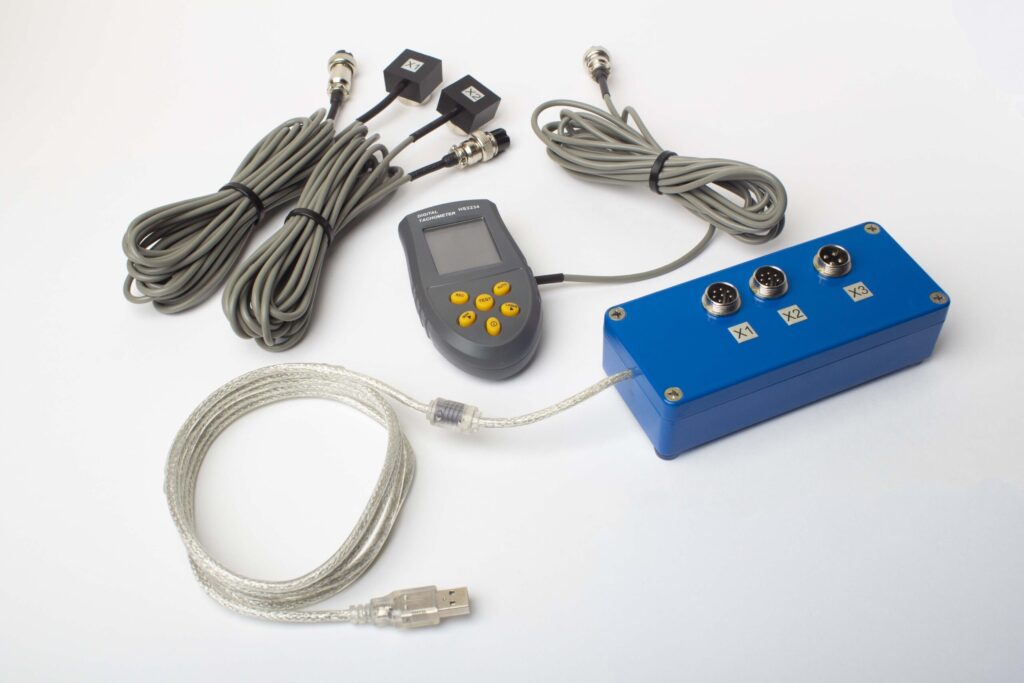
O que há no Kit Completo
€1.975 · Kit Completo, em estoque, nota fiscal com IVA
- Unidade de medição de interface (USB, 2 canais)
- Dois acelerômetros de vibração (cabo de 4 m, 10 m opcional)
- Tacômetro a laser / sensor de fase óptico (50–500 mm)
- Suporte magnético para o sensor
- Balança digital para massas de teste e correção
- Software de balanceamento e análise para Windows
- Estojo de transporte em plástico
Kit Completo
Unidade · 2 sensores · tacômetro a laser · suporte magnético · balança digital · software · estojo de transporte. Tudo o que é necessário para começar a balancear direto da caixa.
Conjunto OEM
Unidade · 2 sensores · tacômetro a laser · software. Para integradores que já possuem suporte, balança e estojo, ou que incorporam a unidade em uma máquina de balanceamento.
| Parâmetro | Valor |
|---|---|
| Canais de medição | 2 (balanceamento em plano único e em dois planos) |
| Faixa de velocidade de vibração | 0,2–80 mm/s RMS |
| Faixa de frequência | 5–1000 Hz (≤10% de erro de amplitude acima de 550 Hz) |
| Precisão de medição | ±5% da escala total |
| Método | Coeficientes de influência de 3 medições (1 ou 2 planos) |
| Análise | Amplitude e fase em 1×, espectro FFT e forma de onda, relatórios salvos |
| Computador portátil | Não incluído (PC com Windows, disponível sob solicitação) |
Casos reais de redução de vibração
Quando o balanceamento não ajuda
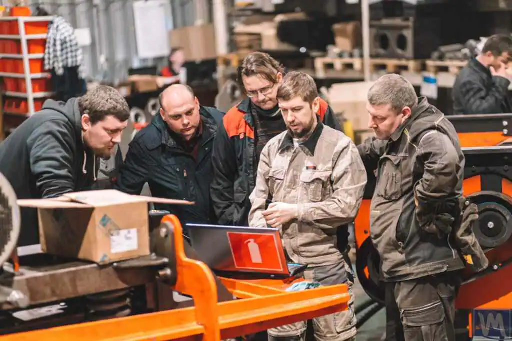
Diagnóstico sistemático de uma máquina em que as correções de balanceamento não conseguiram reduzir a vibração — e qual foi a causa real encontrada.
Com que frequência verificar
Intervalos recomendados de monitoramento de vibração para diferentes tipos de máquina e ambientes de operação.
Guia de balanceamento em campo
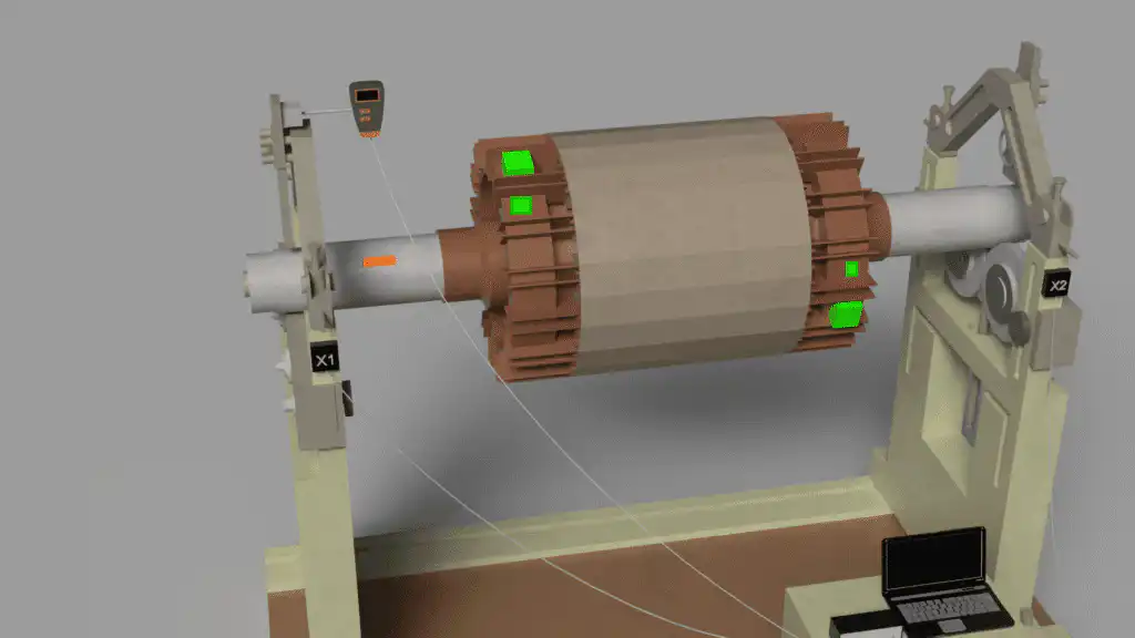
Teoria, prática e resolução de problemas para balanceamento de rotores em campo com o instrumento Balanset-1A.
Calculadoras gratuitas de vibração e balanceamento
FAQ de redução de vibração
Balanceei o rotor, mas a máquina ainda vibra — por quê?
Como sei se o problema é desbalanceamento ou desalinhamento?
Posso balancear uma máquina que também tem dano no mancal?
Qual nível de vibração é aceitável de acordo com a ISO 20816?
Com que frequência devo verificar a vibração e balancear equipamentos rotativos?
E se a vibração retornar logo após o balanceamento?
Aprenda a teoria
Diagnostique a falha — depois elimine-a
O Balanset-1A mede a amplitude de vibração, a fase e o espectro FFT completo para que você confirme a causa raiz antes de se comprometer com uma correção, e então balanceia qualquer rotor rígido em seus próprios mancais na velocidade de operação, documentando o resultado conforme a ISO 20816 e a ISO 21940-11.

