
PORTABLE BALANCER ""บาลานเซ็ต-1เอ""
ระบบปรับสมดุลแบบไดนามิกที่ใช้พีซีแบบสองช่องสัญญาณ
OPERATION MANUAL
rev. 1.56 May 2023
2023 | โปรตุเกส, ปอร์โต
หมายเหตุด้านความปลอดภัย: อุปกรณ์นี้สอดคล้องกับมาตรฐานความปลอดภัยของสหภาพยุโรป ผลิตภัณฑ์เลเซอร์คลาส 2 ปฏิบัติตามขั้นตอนความปลอดภัยของอุปกรณ์แบบหมุน ดูข้อมูลความปลอดภัยฉบับเต็มด้านล่าง →
1. ภาพรวมระบบสมดุล
Balanset-1A balancer ให้บริการปรับสมดุลแบบไดนามิกระนาบเดียวและสองระนาบสำหรับพัดลม ล้อเจียร แกนหมุน เครื่องบด ปั๊ม และเครื่องจักรหมุนอื่นๆ
เครื่องปรับสมดุล Balanset-1A ประกอบด้วยเซ็นเซอร์วัดการสั่นสะเทือน (มาตรวัดความเร่ง) สองตัว เซ็นเซอร์วัดเฟสเลเซอร์ (มาตรวัดความเร็วรอบ) หน่วยเชื่อมต่อ USB 2 ช่องสัญญาณพร้อมพรีแอมพลิฟายเออร์ ตัวรวมสัญญาณ และโมดูลรับสัญญาณ ADC และซอฟต์แวร์ปรับสมดุลบนระบบปฏิบัติการ Windows Balanset-1A ต้องใช้โน้ตบุ๊กหรือพีซีที่ใช้งานร่วมกับ Windows (WinXP...Win11, 32 หรือ 64 บิต) ได้.
Balancing software provides the correct balancing solution for single-plane and two-plane balancing automatically. บาลานเซ็ต-1A is simple to use for non-vibration experts.
All balancing results saved in archive and can be used to create the reports.
คุณสมบัติหลัก
ใช้งานง่าย
- • มวลทดลองที่ผู้ใช้สามารถเลือกได้
- • ป๊อปอัพตรวจสอบความถูกต้องของการทดลองในวงกว้าง
- • การป้อนข้อมูลด้วยตนเอง
ความสามารถในการวัด
- • รอบต่อนาที แอมพลิจูด และเฟส
- • การวิเคราะห์สเปกตรัม FFT
- • การแสดงผลรูปคลื่นและสเปกตรัม
- • การรับส่งข้อมูลพร้อมกันสองช่องทาง
ฟังก์ชันขั้นสูง
- • ค่าสัมประสิทธิ์อิทธิพลที่บันทึกไว้
- • การปรับสมดุล
- • การคำนวณความเยื้องศูนย์ของแกนหมุน.
- • การคำนวณค่าความคลาดเคลื่อนตามมาตรฐาน ISO 1940.
การจัดการข้อมูล
- • พื้นที่จัดเก็บข้อมูลการปรับสมดุลแบบไม่จำกัด
- • การจัดเก็บรูปคลื่นการสั่นสะเทือน
- • เอกสารและรายงาน
เครื่องมือคำนวณ
- • การคำนวณน้ำหนักแบบแยกส่วน
- • การคำนวณการเจาะ
- • การเปลี่ยนระนาบการแก้ไข
- • การแสดงผลด้วยกราฟเชิงขั้ว
ตัวเลือกการวิเคราะห์
- • ถอดหรือคงน้ำหนักทดลองไว้
- • แผนภูมิ RunDown (ทดลอง)
2. SPECIFICATION
| พารามิเตอร์ | ข้อมูลจำเพาะ |
|---|---|
| Measurement range of the root-mean-square value (RMS) of the vibration velocity, mm/sec (for 1x vibration) | from 0.02 to 100 |
| The frequency range of the RMS measurement of the vibration velocity, Hz | ตั้งแต่ 5 ถึง 550 |
| Number of the correction planes | 1 or 2 |
| Range of the frequency of rotation measurement, rpm | 100 – 100000 |
| Range of the vibration phase measurement, angular degrees | from 0 to 360 |
| Error of the vibration phase measurement, angular degrees | ± 1 |
| ความแม่นยำในการวัดความเร็วการสั่นสะเทือน RMS | ±(0.1 + 0.1×โวลต์วัด) มม./วินาที |
| ความแม่นยำในการวัดความถี่การหมุน | ±(1 + 0.005×Nวัด) รอบต่อนาที |
| เวลาเฉลี่ยระหว่างความล้มเหลว (MTBF), ชั่วโมง, นาที | 1000 |
| อายุการใช้งานเฉลี่ย ปี นาที | 6 |
| ขนาด (ในกล่องแข็ง) ซม. | 39*33*13 |
| มวล, กก. | <5 |
| ขนาดโดยรวมของเซ็นเซอร์สั่นสะเทือน มม. สูงสุด | 25*25*20 |
| มวลของเซ็นเซอร์สั่นสะเทือน กก. สูงสุด | 0.04 |
|
เงื่อนไขการใช้งาน: - ช่วงอุณหภูมิ: ตั้งแต่ 5°C ถึง 50°C - ความชื้นสัมพัทธ์: < 85%, ไม่อิ่มตัว - ปราศจากสนามแม่เหล็กไฟฟ้าแรงสูงและแรงกระแทกรุนแรง |
|
3. PACKAGE
เครื่องบาลานซ์ Balanset-1A ประกอบด้วยเครื่องวัดความเร่งแกนเดี่ยว 2 เครื่อง, เครื่องหมายอ้างอิงเฟสเลเซอร์ (เครื่องวัดรอบดิจิตอล), หน่วยอินเทอร์เฟซ USB 2 ช่องพร้อมพรีแอมป์, อินทิเกรเตอร์ และโมดูลการรับ ADC และซอฟต์แวร์ปรับสมดุลที่ใช้ Windows
ชุดจัดส่ง
| Description | Number | Note |
|---|---|---|
| USB interface unit | 1 | |
| Laser phase reference marker (tachometer) | 1 | |
| เครื่องวัดความเร่งแบบแกนเดี่ยว | 2 | |
| Magnetic stand | 1 | |
| Digital scales | 1 | |
| Hard case for transportation | 1 | |
| "คู่มือการใช้งาน "Balanset-1A". | 1 | |
| Flash disk with balancing software | 1 |
4. BALANCE PRINCIPLES
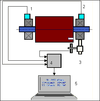
4.1. ""Balanset-1A" ประกอบด้วย (รูปที่ 4.1) หน่วยอินเทอร์เฟซ USB (1)เครื่องวัดความเร่งสองตัว (2) and (3), เครื่องหมายอ้างอิงเฟส (4) และพีซีพกพา (ไม่ได้ให้มาด้วย) (5).
ชุดจัดส่งยังรวมขาตั้งแม่เหล็กด้วย (6) ใช้สำหรับติดตั้งเครื่องหมายอ้างอิงเฟสและเครื่องชั่งดิจิทัล 7.
X1 and X2 connectors intended for connection of the vibration sensors respectively to 1 and 2 measuring channels, and the X3 connector used for connection of the phase reference marker.
The USB cable provides power supply and connection of the USB interface unit to the computer.

รูปที่ 4.1 ชุดส่งมอบของ "Balanset-1A""
การสั่นสะเทือนทางกลทำให้เกิดสัญญาณไฟฟ้าที่เป็นสัดส่วนกับความเร่งของการสั่นสะเทือนที่เอาต์พุตของเซ็นเซอร์การสั่นสะเทือน สัญญาณดิจิทัลจากโมดูล ADC จะถูกถ่ายโอนผ่าน USB ไปยังพีซีพกพา (5). เครื่องหมายอ้างอิงเฟสจะสร้างสัญญาณพัลส์ที่ใช้ในการคำนวณความถี่การหมุนและมุมเฟสการสั่น ซอฟต์แวร์บน Windows มอบโซลูชันสำหรับการปรับสมดุลระนาบเดียวและสองระนาบ การวิเคราะห์สเปกตรัม แผนภูมิ รายงาน และการจัดเก็บค่าสัมประสิทธิ์อิทธิพล
5. SAFETY PRECAUTIONS
⚡ ข้อควรระวัง - ความปลอดภัยทางไฟฟ้า
5.1. When operating on 220V electrical safety regulations must be observed. It is not allowed to repair the device when connected to 220 V.
5.2. หากคุณใช้งานเครื่องใช้ไฟฟ้าในสภาพแวดล้อมที่มีกระแสไฟฟ้าสลับคุณภาพต่ำ หรือมีสัญญาณรบกวนจากเครือข่าย ขอแนะนำให้ใช้แหล่งจ่ายไฟอิสระจากแบตเตอรี่ของคอมพิวเตอร์.
⚠️ ข้อกำหนดด้านความปลอดภัยเพิ่มเติมสำหรับอุปกรณ์หมุน
- !การล็อคเครื่องจักร: ปฏิบัติตามขั้นตอนการล็อคเอาต์/แท็กเอาต์ที่ถูกต้องเสมอ ก่อนที่จะติดตั้งเซ็นเซอร์
- !อุปกรณ์ป้องกันส่วนบุคคล: สวมแว่นตานิรภัย อุปกรณ์ป้องกันการได้ยิน และหลีกเลี่ยงการสวมเสื้อผ้าหลวมๆ ใกล้เครื่องจักรที่กำลังหมุน
- !การติดตั้งที่ปลอดภัย: ตรวจสอบให้แน่ใจว่าเซ็นเซอร์และสายเคเบิลทั้งหมดยึดแน่นและไม่สามารถถูกชิ้นส่วนหมุนจับได้
- !ขั้นตอนการฉุกเฉิน: ทราบตำแหน่งของจุดหยุดฉุกเฉินและขั้นตอนการปิดระบบ
- !การฝึกอบรม: เฉพาะบุคลากรที่ได้รับการฝึกอบรมเท่านั้นที่ควรใช้งานอุปกรณ์ปรับสมดุลบนเครื่องจักรหมุน
6. การตั้งค่าซอฟต์แวร์และฮาร์ดแวร์
6.1. USB drivers and balancing software installation
Before working install drivers and balancing software.
รายการโฟลเดอร์และไฟล์
Installation disk (flash drive) contains the following files and folders:
- Bs1Av###Setup – โฟลเดอร์ที่มีซอฟต์แวร์ปรับสมดุล "Balanset-1A" (### – หมายเลขเวอร์ชัน)
- อาร์ดไดร์ฟ – ไดรเวอร์ USB
- คู่มือ EBalancer.pdf – คู่มือนี้
- Bal1Av###Setup.exe – ไฟล์ติดตั้ง ไฟล์นี้ประกอบด้วยไฟล์และโฟลเดอร์ที่บีบอัดทั้งหมดที่กล่าวถึงข้างต้น ### – เวอร์ชันของซอฟต์แวร์ "Balanset-1A".
- อีบาลานซ์.ซีเอฟจี – ค่าความไว
- บาล.อินี่ – ข้อมูลการเริ่มต้นบางส่วน
ขั้นตอนการติดตั้งซอฟต์แวร์
For installing drivers and specialized software run file Bal1Av###Setup.exe and follow setup instructions by pressing buttons «Next», «ОК» etc.
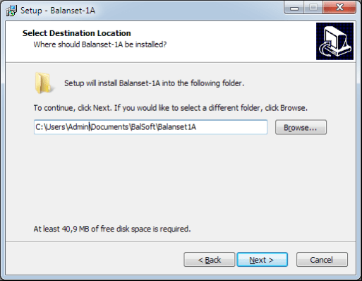
Choose setup folder. Usually the given folder should not be changed.
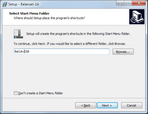
Then the program requires specifying Program group and desktop folders. Press button Next.
งานติดตั้งตกแต่งขั้นสุดท้าย
- ✓Install sensors on the inspected or balanced mechanism (Detailed information about how to install the sensors is given in Annex 1)
- ✓Connect vibration sensors 2 and 3 to the inputs X1 and X2, and phase angle sensor to the input X3 of USB interface unit.
- ✓Connect USB interface unit to the USB-port of the computer.
- ✓เมื่อใช้แหล่งจ่ายไฟ AC ให้เชื่อมต่อคอมพิวเตอร์เข้ากับแหล่งจ่ายไฟหลัก ต่อแหล่งจ่ายไฟเข้ากับ 220 V, 50 Hz
- ✓คลิกไอคอนทางลัด "Balanset-1A" บนเดสก์ท็อป.
7. ซอฟต์แวร์ปรับสมดุล
7.1. ทั่วไป
Initial window
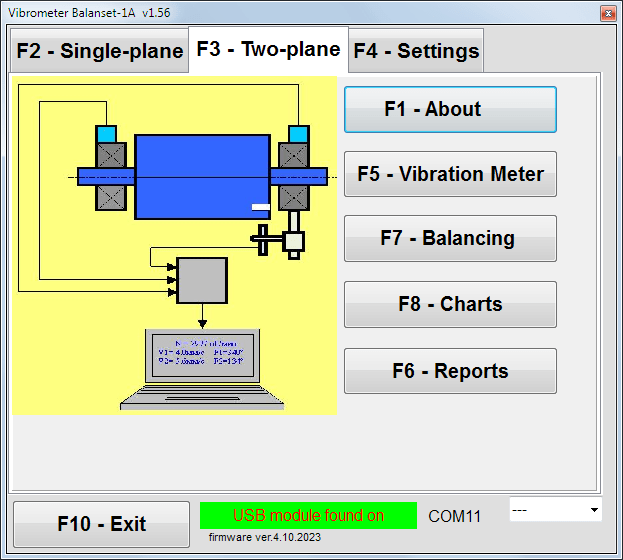
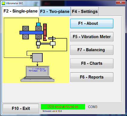
เมื่อเรียกใช้โปรแกรม "Balanset-1A" หน้าต่างเริ่มต้นดังแสดงในรูปที่ 7.1 จะปรากฏขึ้น.

รูปที่ 7.1. หน้าต่างเริ่มต้นของ "Balanset-1A""
มีปุ่ม 9 ปุ่มในหน้าต่างเริ่มต้นพร้อมชื่อของฟังก์ชั่นที่เกิดขึ้นเมื่อคลิกที่ปุ่มเหล่านั้น
F1-«About»
รูปที่ 7.2 หน้าต่าง F1-«เกี่ยวกับ»
F2-«Single plane», F3-«Two plane»
การกด ""F2- เครื่องบินลำเดียว"" (หรือ F2 ปุ่มฟังก์ชันบนแป้นพิมพ์คอมพิวเตอร์) เลือกการวัดการสั่นสะเทือนบนช่องสัญญาณ X1.
After clicking this button, the computer display diagram shown in Fig. 7.1 illustrating a process of measuring the vibration only on the first measuring channel (or the balancing process in a single plane).
การกด ""F3-สองระนาบ"" (หรือ F3 function key on the computer keyboard) selects the mode of vibration measurements on two channels X1 and X2 simultaneously. (Fig. 7.3.)
รูปที่ 7.3. หน้าต่างเริ่มต้นของ "Balanset-1A" การปรับสมดุลสองระนาบ.
F4 – «การตั้งค่า»
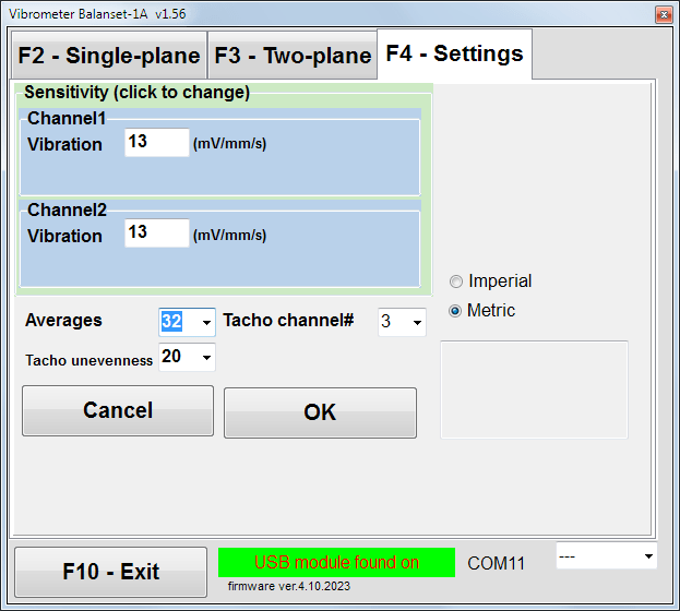
รูปที่ 7.4 หน้าต่าง "การตั้งค่า"
In this window you can change some Balanset-1A settings.
- Sensitivity. The nominal value is 13 mV / mm/s.
Changing the sensitivity coefficients of sensors is required only when replacing sensors!
Attention!
เมื่อคุณป้อนค่าสัมประสิทธิ์ความไว ส่วนที่เป็นทศนิยมจะถูกคั่นด้วยจุดทศนิยม (เครื่องหมาย ",") จากส่วนที่เป็นจำนวนเต็ม.
- Averaging - จำนวนครั้งในการหาค่าเฉลี่ย (จำนวนรอบการหมุนของโรเตอร์ที่ใช้ในการหาค่าเฉลี่ยเพื่อให้ได้ความแม่นยำยิ่งขึ้น)
- Tacho channel# - ช่อง # เชื่อมต่อเครื่องวัดความเร็วรอบแล้ว โดยค่าเริ่มต้นจะเป็นช่องที่ 3.
- Unevenness - ความแตกต่างของระยะเวลาระหว่างพัลส์ทาโคที่อยู่ติดกัน ซึ่งข้างต้นทำให้เกิดคำเตือน ""Failure of the tachometer"
- Imperial/Metric - เลือกหน่วยวัดที่เหมาะสม.
Com port number is assigned automatically.
F5 – «เครื่องวัดการสั่นสะเทือน»
Pressing this button (or a function key of F5 (บนแป้นพิมพ์คอมพิวเตอร์) จะเปิดใช้งานโหมดการวัดการสั่นสะเทือนบนช่องวัดหนึ่งหรือสองช่องของเครื่องวัดการสั่นสะเทือนเสมือนจริง ขึ้นอยู่กับสภาพของปุ่ม"F2-ระนาบเดียว", ""F3-สองระนาบ".
F6 – «รายงาน»
Pressing this button (or F6 function key on the computer keyboard) switches on the balancing Archive, from which you can print the report with the results of balancing for a specific mechanism (rotor).
F7 – «Balancing»
การกดปุ่มนี้ (หรือปุ่มฟังก์ชัน F7 บนแป้นพิมพ์ของคุณ) จะเปิดใช้งานโหมดปรับสมดุลในระนาบการแก้ไขหนึ่งหรือสองระนาบ ขึ้นอยู่กับโหมดการวัดที่เลือกโดยการกดปุ่มต่างๆ"F2-ระนาบเดียว", ""F3-สองระนาบ".
F8 – «Charts»
Pressing this button (or F8 กดปุ่มฟังก์ชันบนแป้นพิมพ์คอมพิวเตอร์เพื่อเปิดใช้งานมิเตอร์วัดการสั่นสะเทือนแบบกราฟิก ซึ่งจะแสดงค่าดิจิทัลของแอมพลิจูดและเฟสของการสั่นสะเทือนพร้อมกับกราฟแสดงค่าตามเวลาบนหน้าจอพร้อมกัน.
F10 – «ออก»
Pressing this button (or F10 กดปุ่มฟังก์ชันบนแป้นพิมพ์คอมพิวเตอร์เพื่อเสร็จสิ้นโปรแกรม "Balanset-1A".
7.2. "เครื่องวัดการสั่นสะเทือน""
ก่อนที่จะทำงานใน ""Vibration meter"ในโหมดนี้ ให้ติดตั้งเซ็นเซอร์วัดการสั่นสะเทือนบนเครื่องจักร และเชื่อมต่อเซ็นเซอร์เหล่านั้นเข้ากับขั้วต่อ X1 และ X2 ของหน่วยอินเทอร์เฟซ USB ตามลำดับ ส่วนเซ็นเซอร์วัดความเร็วรอบ ให้เชื่อมต่อเข้ากับอินพุต X3 ของหน่วยอินเทอร์เฟซ USB.

Fig. 7.5 USB interface unit
วางเทปสะท้อนแสงบนพื้นผิวของโรเตอร์สำหรับการทำงานของเครื่องวัดความเร็วรอบ

รูปที่ 7.6 เทปสะท้อนแสง
Recommendations for the installation and configuration of sensors are given in Annex 1.
หากต้องการเริ่มการวัดในโหมดเครื่องวัดการสั่นสะเทือน ให้คลิกที่ปุ่ม ""F5 – Vibration Meter"ในหน้าต่างเริ่มต้นของโปรแกรม (ดูรูปที่ 7.1).
Vibration Meter window appears (see. Fig.7.7)

Fig. 7.7. Vibration meter mode. Wave and Spectrum.
หากต้องการเริ่มการวัดการสั่นสะเทือน ให้คลิกปุ่ม ""F9 – รัน"" (หรือกดปุ่มฟังก์ชัน F9 on the keyboard).
If โหมดทริกเกอร์ อัตโนมัติ เมื่อตรวจสอบแล้ว ผลการวัดการสั่นสะเทือนจะแสดงบนหน้าจอเป็นระยะ.
ในกรณีที่มีการวัดการสั่นสะเทือนพร้อมกันในช่องสัญญาณแรกและช่องสัญญาณที่สอง หน้าต่างที่อยู่ใต้คำว่า ""Plane 1"" และ ""Plane 2""จะถูกเติมเต็ม".
การวัดการสั่นสะเทือนในโหมด "Vibration" สามารถทำได้แม้ไม่ได้ต่อเซ็นเซอร์มุมเฟส ในหน้าต่างเริ่มต้นของโปรแกรม ค่าของการสั่นสะเทือน RMS รวม (V1s, V2s) will only be displayed.
มีการตั้งค่าถัดไปในโหมดเครื่องวัดการสั่นสะเทือน
- RMS ต่ำ, เฮิรตซ์ – ความถี่ต่ำสุดในการคำนวณ RMS ของการสั่นสะเทือนโดยรวม
- แบนด์วิดท์ - แถบความถี่การสั่นสะเทือนในแผนภูมิ
- Averages - จำนวนค่าเฉลี่ยเพื่อความแม่นยำในการวัดที่มากขึ้น
เพื่อดำเนินการให้เสร็จสิ้นในโหมด "เครื่องวัดการสั่นสะเทือน" ให้คลิกปุ่ม ""F10 – Exit""และกลับไปยังหน้าต่างเริ่มต้น".

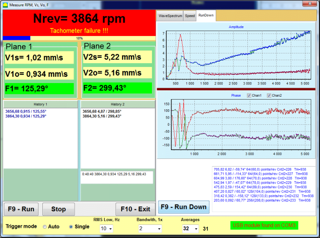
Fig. 7.8. Vibration meter mode. Rotation speed Unevenness, 1x vibration wave form.
Fig. 7.9. Vibration meter mode. Rundown (beta version, no warranty!).
7.3 ขั้นตอนการปรับสมดุล
Balancing is performed for mechanisms in good technical condition and correctly mounted. Otherwise, before the balancing the mechanism must be repaired, installed in proper bearings and fixed. Rotor should be cleaned of contaminants that can hinder from balancing procedure.
Before balancing measure vibration in Vibration meter mode (F5 button) to be sure that mainly vibration is 1x vibration.
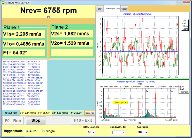
Fig. 7.10. Vibration meter mode. Checking overall (V1s,V2s) and 1x (V1o,V2o) vibration.
หากค่าการสั่นสะเทือนรวม V1 (V2) มีค่าใกล้เคียงกับขนาดของการสั่นสะเทือนที่ความถี่การหมุน (1x การสั่นสะเทือน) V1o (V2o) ก็สามารถสันนิษฐานได้ว่าปัจจัยหลักที่ส่งผลต่อกลไกการสั่นสะเทือนนั้นมาจากความไม่สมดุลของโรเตอร์ หากค่าการสั่นสะเทือนรวม V1 (V2) สูงกว่าค่าการสั่นสะเทือน 1x V1o (V2o) มาก ขอแนะนำให้ตรวจสอบสภาพกลไก เช่น สภาพของตลับลูกปืน ฐานยึด ตรวจสอบให้แน่ใจว่าไม่มีการสัมผัสระหว่างชิ้นส่วนที่ยึดกับโรเตอร์ในระหว่างการหมุน เป็นต้น
คุณควรใส่ใจกับความเสถียรของค่าที่วัดได้ในโหมดเครื่องวัดการสั่นสะเทือนด้วย โดยแอมพลิจูดและเฟสของการสั่นสะเทือนไม่ควรเปลี่ยนแปลงเกิน 10-15% ในกระบวนการวัด มิฉะนั้น อาจสันนิษฐานได้ว่ากลไกทำงานในบริเวณใกล้เคียงกับจุดเรโซแนนซ์ ในกรณีนี้ ให้เปลี่ยนความเร็วในการหมุนของโรเตอร์ และหากทำไม่ได้ ให้เปลี่ยนเงื่อนไขการติดตั้งเครื่องจักรบนฐานราก (เช่น ติดตั้งเครื่องจักรบนฐานรองรับแบบสปริงชั่วคราว)
สำหรับการปรับสมดุลโรเตอร์ วิธีค่าสัมประสิทธิ์อิทธิพล ควรใช้วิธีการปรับสมดุล (3 รอบ)
Trial runs are done to determine the effect of trial mass on vibration change, mass and place (angle) of installation of correction weights.
First determine the original vibration of a mechanism (first start without weight), and then set the trial weight to the first plane and made the second start. Then, remove the trial weight from the first plane, set in a second plane and made the second start.
The program then calculates and indicates on the screen the weight and location (angle) of installation of correction weights.
When balancing in a single plane (static), the second start is not required.
Trial weight is set to an arbitrary location on the rotor where it is convenient, and then the actual radius is entered in the setup program.
(Position Radius is used only for calculating the unbalance amount in grams * mm)
Important!
- Measurements should be carried out with the constant speed of rotation of the mechanism!
- Correction weights must be installed on the same radius as the trial weights!
เลือกมวลของตุ้มน้ำหนักทดลองเพื่อให้แอมพลิจูดของการสั่นสะเทือนเปลี่ยนแปลงอย่างมีนัยสำคัญหลังจากช่วงการติดตั้ง (> 20-30°) และ (20-30%) หากการเปลี่ยนแปลงน้อยเกินไป ความคลาดเคลื่อนจะเพิ่มขึ้นอย่างมากในการคำนวณครั้งต่อไป ตั้งค่ามวลทดลองในตำแหน่งเดิม (มุมเดียวกัน) กับเครื่องหมายเฟสได้อย่างสะดวก
สูตรคำนวณมวลน้ำหนักทดลอง
Mt = Mr × Ksupport × Kvibration / (Rt × (N/100)²)
ที่ไหน:
- ภูเขา - น้ำหนักทดลอง, กรัม
- นาย - มวลของโรเตอร์, g
- เคซัพพอร์ต - ค่าสัมประสิทธิ์ความแข็งรองรับ (1-5)
- การสั่นสะเทือน - ค่าสัมประสิทธิ์ระดับการสั่นสะเทือน (0.5-2.5)
- ถนน - รัศมีการติดตั้งน้ำหนักทดสอบ (ซม.)
- เอ็น - ความเร็วรอบของโรเตอร์ (rpm)
ค่าสัมประสิทธิ์ความแข็งรองรับ (Ksupport):
- 1.0 - ตัวรองรับนุ่มมาก (ยางกันกระแทก)
- 2.0-3.0 - ความแข็งปานกลาง (ลูกปืนมาตรฐาน)
- 4.0-5.0 - โครงสร้างรองรับแบบแข็ง (ฐานรากขนาดใหญ่)
ค่าสัมประสิทธิ์ระดับการสั่นสะเทือน (Kvibration):
- 0.5 - การสั่นสะเทือนต่ำ (ไม่เกิน 5 มม./วินาที)
- 1.0 - การสั่นสะเทือนปกติ (5-10 มม./วินาที)
- 1.5 - การสั่นสะเทือนสูง (10-20 มม./วินาที)
- 2.0 - การสั่นสะเทือนสูง (20-40 มม./วินาที)
- 2.5 - การสั่นสะเทือนสูงมาก (>40 มม./วินาที)
🔗 ใช้เครื่องคำนวณออนไลน์ของเรา:
เครื่องคำนวณน้ำหนักทดลอง →⚠️ สำคัญ!
After each test run trial mass are removed! Correction weights set at an angle calculated from the place of trial weight installation in the direction of rotation of the rotor!
คำอธิบายการคำนวณมุม:
มุมติดตั้งน้ำหนักการแก้ไขคือ เสมอ นับจากจุดติดตั้งน้ำหนักทดลองในทิศทางของการหมุนของโรเตอร์.
- ศูนย์จุด (0°) ตำแหน่งที่แน่นอนที่คุณติดตั้งน้ำหนักทดลองจะกลายเป็นจุดอ้างอิงของคุณ (0 องศา).
- ทิศทาง: วัดมุมในทิศทางเดียวกับที่โรเตอร์หมุน.
ตัวอย่าง: หากโรเตอร์หมุนตามเข็มนาฬิกา ให้วัดมุมตามเข็มนาฬิกาจากตำแหน่งน้ำหนักทดลอง. - การตีความ: หากโปรแกรมแสดงมุมของ 120 องศา, คุณต้องติดตั้งน้ำหนักปรับแก้ 120 องศาข้างหน้า ของตำแหน่งน้ำหนักทดลองในทิศทางของการหมุน.
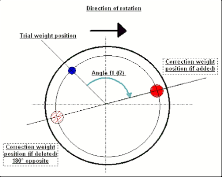
Fig. 7.11. Correction weight mounting.
ที่แนะนำ!
ก่อนทำการปรับสมดุลแบบไดนามิก ขอแนะนำให้ตรวจสอบให้แน่ใจว่าค่าความไม่สมดุลสถิตไม่สูงเกินไป สำหรับโรเตอร์ที่มีแกนนอน สามารถหมุนโรเตอร์ด้วยมือได้ 90 องศาจากตำแหน่งปัจจุบัน หากโรเตอร์ไม่สมดุลสถิต โรเตอร์จะหมุนไปยังตำแหน่งสมดุล เมื่อโรเตอร์เข้าสู่ตำแหน่งสมดุลแล้ว จำเป็นต้องติดตั้งตุ้มถ่วงน้ำหนักไว้ที่จุดสูงสุดประมาณช่วงกลางของความยาวโรเตอร์ ควรเลือกตุ้มถ่วงน้ำหนักในลักษณะที่โรเตอร์ไม่เคลื่อนที่ในตำแหน่งใดๆ
การปรับสมดุลล่วงหน้าดังกล่าวจะช่วยลดปริมาณการสั่นสะเทือนในช่วงเริ่มต้นครั้งแรกของโรเตอร์ที่ไม่สมดุลอย่างมาก
การติดตั้งและยึดเซ็นเซอร์
วีibration sensor must be installed on the machine in the selected measuring point and connected to the input X1 of the USB interface unit.
มีการกำหนดค่าการติดตั้งสองแบบ:
- แม่เหล็ก
- Threaded studs M4
Optical tacho sensor should be connected to the input X3 of the USB interface unit. Furthermore, for use of this sensor a special reflecting mark should be applied on surface of a rotor.
📏 ข้อกำหนดในการติดตั้งเซ็นเซอร์แสง
- ✓ระยะห่างจากผิวโรเตอร์: 50-500 มม. (ขึ้นอยู่กับรุ่นเซ็นเซอร์)
- ✓ความกว้างของเทปสะท้อนแสง: ขั้นต่ำ 1-1.5 ซม. (ขึ้นอยู่กับความเร็วและรัศมี)
- ✓ปฐมนิเทศ: ตั้งฉากกับพื้นผิวโรเตอร์
- ✓การติดตั้ง: ใช้ขาตั้งแม่เหล็กหรือที่หนีบเพื่อการวางตำแหน่งที่มั่นคง
- ✓หลีกเลี่ยงแสงแดดโดยตรง หรือแสงประดิษฐ์ที่สว่างบนเซ็นเซอร์/เทป
💡 การคำนวณความกว้างของเทป: เพื่อประสิทธิภาพสูงสุด ให้คำนวณความกว้างของเทปโดยใช้:
L ≥ (N × R)/30000 ≥ 1.0-1.5 ซม.
โดยที่: L - ความกว้างของเทป (ซม.), N - ความเร็วรอบของโรเตอร์ (รอบต่อนาที), R - รัศมีของเทป (ซม.)
Detailed requirements on site selection of the sensors and their attachment to the object when balancing are set out in Annex 1.
7.4 การปรับสมดุลระนาบเดี่ยว
รูปที่ 7.12 "การปรับสมดุลระนาบเดียว"
การเก็บถาวรแบบสมดุล
เพื่อเริ่มต้นการทำงานในโครงการใน ""Single-Plane balancing"โหมด " คลิกที่ ""F2-Single-plane"กดปุ่ม " (หรือกดปุ่ม F2 บนแป้นพิมพ์คอมพิวเตอร์).
จากนั้นคลิกที่ ""F7 – Balancing"ปุ่ม " หลังจากนั้น Single Plane balancing archive window will appear, in which the balancing data will be saved (see Fig. 7.13).

Fig. 7.13 The window for selecting the balancing archive in single plane.
In this window, you need to enter data on the name of the rotor (Rotor name), place of rotor installation (Place), tolerances for vibration and residual imbalance (Tolerance), date of measurement. This data is stored in a database. Also, a folder Arc### is created in, where ### is the number of the archive in which the charts, a report file, etc. will be saved. After the balancing is completed, a report file will be generated that can be edited and printed in the built-in editor.
หลังจากป้อนข้อมูลที่จำเป็นแล้ว คุณต้องคลิก ""F10-OK"ปุ่ม " หลังจากนั้น ""Single-Plane balancing"หน้าต่างจะเปิดขึ้น (ดูรูปที่ 7.13)
Balancing settings (1-plane)

Fig. 7.14. Single plane. Balancing settings
ด้านซ้ายของหน้าต่างนี้จะแสดงข้อมูลการวัดการสั่นสะเทือนและปุ่มควบคุมการวัด"Run # 0", "Run # 1", "RunTrim".
ทางด้านขวาของหน้าต่างนี้มีแท็บสามแท็บ:
- Balancing settings
- Charts
- Result
""Balancing settings"ปุ่ม "tab" ใช้สำหรับเข้าสู่การตั้งค่าการปรับสมดุล:
- ""ค่าสัมประสิทธิ์อิทธิพล"" -
- "New Rotor"" - การเลือกการปรับสมดุลของโรเตอร์ใหม่ ซึ่งไม่มีค่าสัมประสิทธิ์การปรับสมดุลที่บันทึกไว้ และต้องทำการทดสอบสองครั้งเพื่อกำหนดมวลและมุมการติดตั้งของตุ้มน้ำหนักปรับแก้.
- "Saved coeff."" - การเลือกการปรับสมดุลโรเตอร์ใหม่ ซึ่งมีค่าสัมประสิทธิ์การปรับสมดุลที่บันทึกไว้ และต้องการเพียงการทำงานเพียงครั้งเดียวเพื่อกำหนดน้ำหนักและมุมการติดตั้งของตุ้มถ่วงแก้ไข".
- ""น้ำหนักทดลอง"" -
- "Percent""- น้ำหนักที่ปรับแก้จะคำนวณเป็นเปอร์เซ็นต์ของน้ำหนักตอนทดลอง".
- "Gram""- ป้อนค่ามวลที่ทราบของตุ้มน้ำหนักทดลอง และคำนวณมวลของตุ้มน้ำหนักแก้ไข" grams or in oz for Imperial system.
⚠️ โปรดทราบ! หากจำเป็นต้องใช้ ""Saved coeff.""สำหรับขั้นตอนการปรับสมดุลเบื้องต้น ต้องป้อนค่ามวลทดสอบเป็นกรัมหรือออนซ์ ไม่ใช่ % เครื่องชั่งมีอยู่ในแพ็คเกจจัดส่ง".
- ""วิธีการกำหนดน้ำหนัก""
- "Free position"- สามารถติดตั้งตุ้มถ่วงน้ำหนักในตำแหน่งเชิงมุมใดๆ บนเส้นรอบวงของใบพัดได้.
- "Fixed position"- สามารถติดตั้งตุ้มน้ำหนักในตำแหน่งเชิงมุมคงที่บนใบพัดได้ เช่น บนใบพัดหรือรู (เช่น 12 รู – 30 องศา) เป็นต้น ต้องป้อนจำนวนตำแหน่งคงที่ในช่องที่เหมาะสม หลังจากปรับสมดุลแล้ว โปรแกรมจะแบ่งตุ้มน้ำหนักออกเป็นสองส่วนโดยอัตโนมัติ และระบุจำนวนตำแหน่งที่จำเป็นต้องติดตั้งตุ้มน้ำหนักที่ได้มา.
- "Circular groove"– ใช้สำหรับปรับสมดุลล้อเจียร ในกรณีนี้จะใช้ตุ้มถ่วง 3 อันเพื่อขจัดความไม่สมดุล”
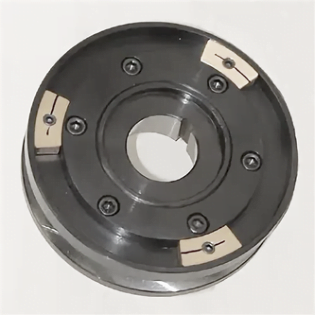
Fig. 7.17 Grinding wheel balancing with 3 counterweights
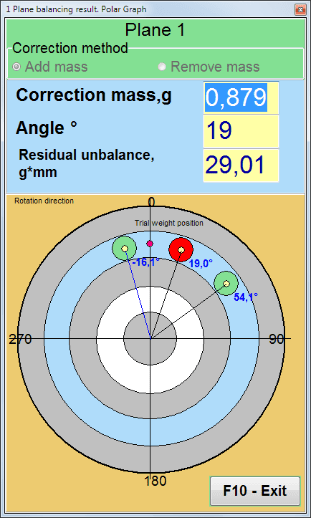
Fig. 7.18 Grinding wheel balancing. Polar graph.

Fig. 7.15. Result tab. Fixed position of correction weight mounting.
Z1 และ Z2 – ตำแหน่งที่ติดตั้งตุ้มน้ำหนักแก้ไข คำนวณจากตำแหน่ง Z1 ตามทิศทางการหมุน Z1 คือตำแหน่งที่ติดตั้งตุ้มน้ำหนักทดลอง
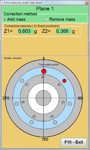
Fig. 7.16 Fixed positions. Polar diagram.
- "Mass mount radius, mm"" - "Plane1" - รัศมีของน้ำหนักทดสอบในระนาบที่ 1 จำเป็นต้องคำนวณขนาดของความไม่สมดุลเริ่มต้นและที่เหลืออยู่ เพื่อตรวจสอบว่าสอดคล้องกับค่าความคลาดเคลื่อนของความไม่สมดุลที่เหลืออยู่หลังจากการปรับสมดุลแล้วหรือไม่.
- "Leave trial weight in Plane1.""โดยปกติแล้ว น้ำหนักทดลองจะถูกนำออกระหว่างกระบวนการปรับสมดุล แต่ในบางกรณีที่ไม่สามารถนำออกได้ คุณจำเป็นต้องทำเครื่องหมายในช่องนี้เพื่อนำน้ำหนักทดลองมาคำนวณด้วย".
- "Manual data input"" - ใช้สำหรับป้อนค่าการสั่นสะเทือนและเฟสด้วยตนเองลงในช่องที่เหมาะสมทางด้านซ้ายของหน้าต่าง และคำนวณมวลและมุมการติดตั้งของตุ้มน้ำหนักปรับแก้เมื่อเปลี่ยนไปใช้ ""Results""แท็บ"
- ปุ่ม ""Restore session data"ระหว่างการปรับสมดุล ข้อมูลที่วัดได้จะถูกบันทึกไว้ในไฟล์ session1.ini หากกระบวนการวัดถูกขัดจังหวะเนื่องจากคอมพิวเตอร์ค้างหรือด้วยเหตุผลอื่น ๆ คุณสามารถกู้คืนข้อมูลการวัดและดำเนินการปรับสมดุลต่อจากจุดที่ขัดจังหวะได้โดยคลิกปุ่มนี้.
- Mandrel eccentricity elimination (Index balancing) Balancing with additional start to eliminate the influence of the eccentricity of the mandrel (balancing arbor). Mount the rotor alternately at 0° and 180° relative to the. Measure the unbalances in both positions.
- Balancing tolerance Entering or calculating residual imbalance tolerances in g x mm (G-classes)
- Use Polar Graph Use polar graph to display balancing results
1-plane Balancing. New rotor
ดังที่กล่าวไว้ข้างต้น ""New Rotor""การปรับสมดุลต้องใช้การทดสอบสองครั้งและการปรับแต่งด้วยเครื่องปรับสมดุลอย่างน้อยหนึ่งครั้ง".
Run#0 (Initial run)
หลังจากติดตั้งเซ็นเซอร์บนโรเตอร์ปรับสมดุลและป้อนพารามิเตอร์การตั้งค่าแล้ว จำเป็นต้องเปิดการหมุนของโรเตอร์ และเมื่อถึงความเร็วในการทำงาน ให้กดปุ่ม ""Run#0"ปุ่ม " เพื่อเริ่มการวัด""Charts"แท็บ "จะเปิดขึ้นในแผงด้านขวา ซึ่งจะแสดงรูปคลื่นและสเปกตรัมของการสั่นสะเทือน" ในส่วนล่างของแท็บ จะมีไฟล์ประวัติเก็บผลลัพธ์ของการเริ่มต้นทั้งหมดพร้อมการอ้างอิงเวลา ไฟล์นี้จะถูกบันทึกไว้ในโฟลเดอร์เก็บถาวรในดิสก์โดยใช้ชื่อ memo.txt
Attention!
Before starting the measurement, it is necessary to turn on the rotation of the rotor of the balancing machine (Run#0) and make sure that the rotor speed is stable.
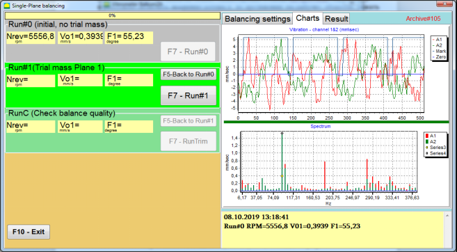
Fig. 7.19. Balancing in one plane. Initial run (Run#0). Charts Tab
After measurement process finished, in the Run#0 ในส่วนแผงด้านซ้ายจะแสดงผลการวัด ได้แก่ ความเร็วรอบของโรเตอร์ (RPM), ค่า RMS (Vo1) และเฟส (F1) ของการสั่นสะเทือน 1x.
""F5-Back to Run#0"ปุ่ม " (หรือปุ่มฟังก์ชัน F5) ใช้สำหรับกลับไปยังส่วน Run#0 และหากจำเป็น ใช้สำหรับวัดค่าพารามิเตอร์การสั่นสะเทือนซ้ำอีกครั้ง.
Run#1 (Trial mass Plane 1)
ก่อนเริ่มการวัดค่าพารามิเตอร์การสั่นสะเทือนในส่วน ""Run#1 (Trial mass Plane 1), ควรติดตั้งตุ้มน้ำหนักทดลองตาม ""Trial weight mass"" สนาม.
The goal of installing a trial weight is to evaluate how the vibration of the rotor changes when a known weight is installed at a known place (angle). Trial weight must changes the vibration amplitude by either 30% lower or higher of initial amplitude or change phase by 30 degrees or more of initial phase.
หากจำเป็นต้องใช้ ""Saved coeff.""เพื่อความสมดุลในการทำงานต่อไป ตำแหน่ง (มุม) ของการติดตั้งตุ้มน้ำหนักทดสอบจะต้องตรงกับตำแหน่ง (มุม) ของเครื่องหมายสะท้อนแสง".
เปิดการหมุนของโรเตอร์เครื่องปรับสมดุลอีกครั้ง และตรวจสอบให้แน่ใจว่าความถี่ในการหมุนคงที่ จากนั้นคลิกที่ ""F7-Run#1"กดปุ่ม " (หรือกดปุ่ม F7 บนแป้นพิมพ์คอมพิวเตอร์).
หลังจากทำการวัดในหน้าต่างที่เกี่ยวข้องของ ""Run#1 (Trial mass Plane 1)"ในส่วนนี้จะแสดงผลการวัดความเร็วรอบของโรเตอร์ (RPM) รวมถึงค่าของส่วนประกอบ RMS (Vо1) และเฟส (F1) ของการสั่นสะเทือน 1x ที่เกิดขึ้น.
ในขณะเดียวกัน ""Result""แท็บจะเปิดขึ้นทางด้านขวาของหน้าต่าง".
This tab displays the results of calculating the mass and angle of corrective weight, which must be installed on the rotor to compensate imbalance.
นอกจากนี้ ในกรณีที่ใช้ระบบพิกัดเชิงขั้ว จอภาพจะแสดงค่ามวล (M1) และมุมการติดตั้ง (f1) ของน้ำหนักแก้ไข
ในกรณีของ ""Fixed positions""หมายเลขของตำแหน่ง (Zi, Zj) และมวลที่แบ่งตามน้ำหนักทดลองจะแสดงขึ้น".
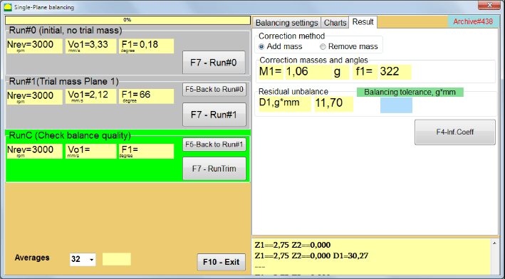
Fig. 7.20. Balancing in one plane. Run#1 and balancing result.
If Polar graph is checked polar diagram will be shown.
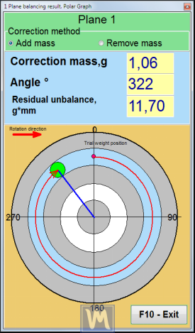
มะเดื่อ 7.21. ผลลัพธ์ของการปรับสมดุล กราฟเชิงขั้ว
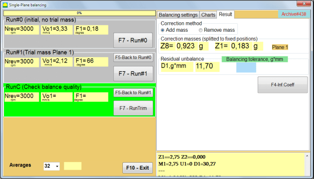
Fig. 7.22. The result of balancing. Weight splitted (fixed positions)
นอกจากนี้ หาก ""Polar graph"หากเลือก "ตรวจสอบแล้ว กราฟเชิงขั้วจะแสดงขึ้น".
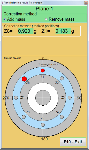
Fig. 7.23. Weight splitted on fixed positions. Polar graph
⚠️ โปรดทราบ!
- หลังจากเสร็จสิ้นกระบวนการวัดในรอบที่สอง (""Run#1 (Trial mass Plane 1)"หากเครื่องปรับสมดุลทำงานผิดปกติ จำเป็นต้องหยุดการหมุนและถอดตุ้มน้ำหนักทดสอบที่ติดตั้งไว้ จากนั้นติดตั้ง (หรือถอด) ตุ้มน้ำหนักแก้ไขบนโรเตอร์ตามข้อมูลในแท็บผลลัพธ์.
หากไม่ได้นำตุ้มน้ำหนักทดลองออก คุณต้องเปลี่ยนไปใช้ ""Balancing settings""กดแท็บและเปิดใช้งานช่องทำเครื่องหมายใน ""Leave trial weight in Plane1"จากนั้นสลับกลับไปที่ ""Result""แท็บ. น้ำหนักและมุมการติดตั้งของตุ้มถ่วงปรับแก้จะถูกคำนวณใหม่โดยอัตโนมัติ".
- ตำแหน่งเชิงมุมของตุ้มน้ำหนักแก้ไขจะดำเนินการจากตำแหน่งที่ติดตั้งตุ้มน้ำหนักทดลอง ทิศทางอ้างอิงของมุมจะสอดคล้องกับทิศทางการหมุนของโรเตอร์
- ในกรณีของ ""Fixed position"" - 1st position (Z1), coincides with the place of installation of the trial weight. The counting direction of the position number is in the direction of rotation of the rotor.
- โดยค่าเริ่มต้น น้ำหนักปรับแก้จะถูกเพิ่มเข้าไปในโรเตอร์ ซึ่งระบุไว้ด้วยป้ายกำกับที่ตั้งไว้ใน ""Add"ช่อง " หากต้องการลดน้ำหนัก (เช่น โดยการเจาะ) คุณต้องทำเครื่องหมายในช่อง ""Delete""ฟิลด์ดังกล่าว หลังจากนั้นตำแหน่งเชิงมุมของตุ้มน้ำหนักปรับแก้จะเปลี่ยนไปโดยอัตโนมัติ 180º".
หลังจากติดตั้งน้ำหนักแก้ไขบนโรเตอร์ปรับสมดุลในหน้าต่างการทำงานแล้ว จำเป็นต้องดำเนินการ RunC (การตัดแต่ง) และประเมินประสิทธิผลของการปรับสมดุลที่ดำเนินการ
RunC (Check balance quality)
⚠️ โปรดทราบ! Before starting the measurement on the RunC, it is necessary to turn on the rotation of the rotor of the machine and make sure that it has entered the operating mode (stable rotation frequency).
เพื่อทำการวัดการสั่นสะเทือนใน ""RunC (Check balance quality)"ส่วน " คลิกที่ ""F7 – RunTrim"กดปุ่ม " (หรือกดปุ่ม F7 บนแป้นพิมพ์).
เมื่อกระบวนการวัดเสร็จสมบูรณ์แล้ว ใน ""RunC (Check balance quality)"ในส่วน "แผงด้านซ้าย" จะแสดงผลลัพธ์ของการวัดความเร็วรอบของโรเตอร์ (RPM) รวมถึงค่าของส่วนประกอบ RMS (Vo1) และเฟส (F1) ของการสั่นสะเทือน 1x.
ใน ""Result"ในแท็บ "ผลลัพธ์ของการคำนวณมวลและมุมการติดตั้งของตุ้มน้ำหนักปรับแก้เพิ่มเติมจะปรากฏขึ้น".
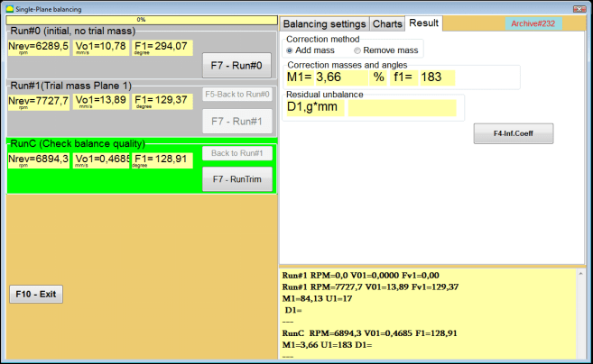
Fig. 7.24. Balancing in one plane. Performing a RunTrim. Result Tab
This weight can be added to the correction weight that is already mounted on the rotor to compensate for the residual imbalance. In addition, the residual rotor unbalance achieved after balancing is displayed in the lower part of this window.
In the case when the amount of residual vibration and / or residual unbalance of the balanced rotor meets the tolerance requirements established in the technical documentation, the balancing process can be completed.
Otherwise, the balancing process may continue. This allows the method of successive approximations to correct possible errors that may occur during the installation (removal) of the corrective weight on a balanced rotor.
เมื่อดำเนินการปรับสมดุลต่อบนโรเตอร์ปรับสมดุล จำเป็นต้องติดตั้ง (หรือถอด) มวลแก้ไขเพิ่มเติม ซึ่งพารามิเตอร์ของมวลแก้ไขเพิ่มเติมนั้นระบุไว้ในส่วน ""Correction masses and angles".
Influence coefficients (1-plane)
""F4-Inf.Coeff"ปุ่ม " ใน ""Result"แท็บนี้ใช้สำหรับดูและจัดเก็บค่าสัมประสิทธิ์การปรับสมดุลโรเตอร์ (ค่าสัมประสิทธิ์อิทธิพล) ที่คำนวณจากผลลัพธ์ของการทดสอบการสอบเทียบลงในหน่วยความจำคอมพิวเตอร์.
เมื่อกดแล้ว ""Influence coefficients (single plane)"หน้าต่าง " จะปรากฏบนหน้าจอคอมพิวเตอร์ โดยจะแสดงค่าสัมประสิทธิ์การปรับสมดุลที่คำนวณจากผลการสอบเทียบ (ทดสอบ) หากในระหว่างการปรับสมดุลเครื่องนี้ในครั้งต่อไป จำเป็นต้องใช้ ""Saved coeff.""โหมด ค่าสัมประสิทธิ์เหล่านี้จะต้องถูกจัดเก็บไว้ในหน่วยความจำของคอมพิวเตอร์".
หากต้องการทำเช่นนี้ ให้คลิก ""F9 - บันทึก"ปุ่ม " และไปที่หน้าสองของ ""ค่าสัมประสิทธิ์อิทธิพล เก็บถาวร ระนาบเดียว"

Fig. 7.25. Balancing coefficients in the 1st plane
จากนั้นคุณต้องป้อนชื่อของเครื่องนี้ลงในช่อง ""Rotor""คอลัมน์และคลิก""F2-Save"ปุ่ม "เพื่อบันทึกข้อมูลที่ระบุลงในคอมพิวเตอร์".
จากนั้นคุณสามารถกลับไปยังหน้าต่างก่อนหน้าได้โดยการกดปุ่ม ""F10-Exit"กดปุ่ม (หรือปุ่มฟังก์ชัน F10 บนแป้นพิมพ์คอมพิวเตอร์).
รูปที่ 7.26. "ค่าสัมประสิทธิ์อิทธิพลที่เก็บถาวร ระนาบเดียว""
Balancing report
หลังจากปรับสมดุลแล้ว ข้อมูลทั้งหมดจะถูกบันทึกและสร้างรายงานการปรับสมดุล คุณสามารถดูและแก้ไขรายงานได้ในตัวแก้ไข ในหน้าต่าง ""การจัดเก็บเอกสารอย่างสมดุลในระนาบเดียว"" (รูปที่ 7.9) กดปุ่ม ""F9 -Report"เพื่อเข้าถึงโปรแกรมแก้ไขรายงานการปรับสมดุล.
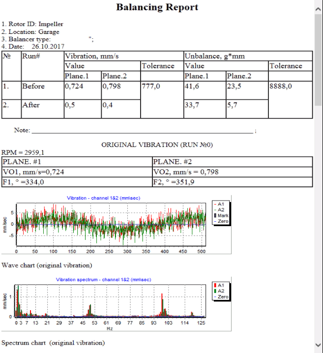
รูปที่ 7.27 รายงานการปรับสมดุล
ขั้นตอนการปรับสมดุลค่าสัมประสิทธิ์ที่บันทึกไว้ด้วยค่าสัมประสิทธิ์อิทธิพลที่บันทึกไว้ใน 1 ระนาบ
การตั้งค่าระบบการวัด (การป้อนข้อมูลเริ่มต้น)
Saved coeff. balancing can be performed on a machine for which balancing coefficients have already been determined and entered into the computer memory.
⚠️ โปรดทราบ! When balancing with saved coefficients, the vibration sensor and the phase angle sensor must be installed in the same way as during the initial balancing.
Input of the initial data for Saved coeff. balancing (เช่นเดียวกับกรณีของหลัก(""New rotor"") การปรับสมดุล) เริ่มต้นใน ""Single plane balancing. Balancing settings.".
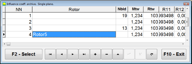
ในกรณีนี้ ใน ""Influence coefficients"ส่วน " ให้เลือก ""Saved coeff"" รายการ ในกรณีนี้คือหน้าสองของ ""Influence coeff. archive. Single plane."ซึ่งจัดเก็บค่าสัมประสิทธิ์การปรับสมดุลที่บันทึกไว้เป็นไฟล์เก็บถาวร".
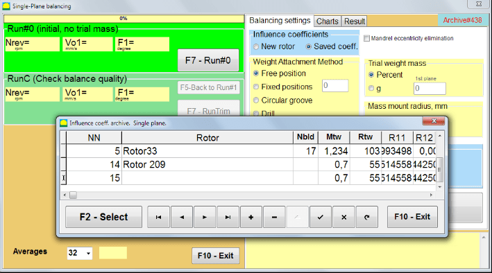
Fig. 7.28. Balancing with saved influence coefficients in 1 plane
การเลื่อนดูตารางในคลังข้อมูลนี้โดยใช้ปุ่มควบคุม "►" หรือ "◄" คุณสามารถเลือกบันทึกที่ต้องการพร้อมค่าสัมประสิทธิ์การปรับสมดุลของเครื่องจักรที่เราสนใจได้ จากนั้น หากต้องการใช้ข้อมูลนี้ในการวัดปัจจุบัน ให้กดปุ่ม ""F2 – Select"" ปุ่ม.
หลังจากนั้น เนื้อหาของหน้าต่างอื่นๆ ทั้งหมดของ ""Single plane balancing. Balancing settings."เครื่องหมาย " จะถูกกรอกโดยอัตโนมัติ".
After completing the input of the initial data, you can begin to measure.
การวัดระหว่างการปรับสมดุลด้วยค่าสัมประสิทธิ์อิทธิพลที่บันทึกไว้
Balancing with saved influence coefficients requires only one initial run and at least one test run of the balancing machine.
⚠️ โปรดทราบ! Before starting the measurement, it is necessary to turn on the rotation of the rotor and make sure that rotating frequency is stable.
เพื่อดำเนินการวัดค่าพารามิเตอร์การสั่นสะเทือนใน ""Run#0 (Initial, no trial mass)"ส่วน " กด ""F7 – Run#0"(หรือกดปุ่ม F7 บนแป้นพิมพ์คอมพิวเตอร์).
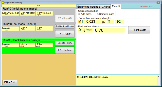
Fig. 7.29. Balancing with saved influence coefficients in one plane. Results after one run.
ในช่องที่เกี่ยวข้องของ ""Run#0"ในส่วนนี้ จะแสดงผลการวัดความเร็วรอบของโรเตอร์ (RPM) ค่าของส่วนประกอบ RMS (Vо1) และเฟส (F1) ของการสั่นสะเทือน 1x.
ในขณะเดียวกัน ""Result"แท็บ "แสดงผลลัพธ์ของการคำนวณมวลและมุมของตุ้มน้ำหนักปรับแก้ ซึ่งต้องติดตั้งบนใบพัดเพื่อชดเชยความไม่สมดุล".
นอกจากนี้ ในกรณีที่ใช้ระบบพิกัดเชิงขั้ว จอภาพจะแสดงค่ามวลและมุมการติดตั้งของน้ำหนักแก้ไข
In the case of splitting of the corrective weight on the fixed positions, the numbers of the positions of the balancing rotor and the mass of weight that need to be installed on them are displayed.
Further, the balancing process is carried out in accordance with the recommendations set out in section 7.4.2. for primary balancing.
Mandrel eccentricity elimination (Index balancing)
If during balancing the rotor is installed in a cylindrical mandrel, then the eccentricity of the mandrel may introduce an additional error. To eliminate this error, the rotor should be deployed in the mandrel 180 degrees and carry out an additional start. This is called index balancing.
To carry out index balancing, a special option is provided in the Balanset-1A program. When checked Mandrel eccentricity elimination an additional RunEcc section appears in the balancing window.

Fig. 7.30. The working window for Index balancing.
After running Run # 1 (Trial mass Plane 1), a window will appear
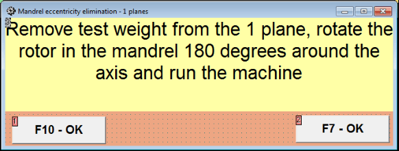
Fig. 7.31 Index balancing attention window.
หลังจากติดตั้งโรเตอร์ด้วยการหมุน 180° แล้ว จะต้องดำเนินการ Run Ecc ให้เสร็จสมบูรณ์ โปรแกรมจะคำนวณความไม่สมดุลที่แท้จริงของโรเตอร์โดยอัตโนมัติโดยไม่กระทบต่อความเยื้องศูนย์ของแกนหมุน
7.5 การปรับสมดุลสองระนาบ
Before starting work in the Two plane balancing mode, it is necessary to install vibration sensors on the machine body at the selected measurement points and connect them to the inputs X1 and X2 of the measuring unit, respectively.
An optical phase angle sensor must be connected to input X3 of the measuring unit. In addition, to use this sensor, a reflective tape must be glued onto the accessible rotor surface of the balancing machine.
Detailed requirements for choosing the installation location of sensors and their mounting at the facility during balancing are set out in Appendix 1.
การดำเนินงานตามโครงการใน ""Two plane balancing"โหมด "เริ่มต้นจากหน้าต่างหลักของโปรแกรม".
คลิกที่ ""F3-Two plane"กดปุ่ม " (หรือกดปุ่ม F3 บนแป้นพิมพ์คอมพิวเตอร์).
นอกจากนี้ ให้คลิกที่ปุ่ม "F7 – การปรับสมดุล" จากนั้นหน้าต่างการทำงานจะปรากฏขึ้นบนหน้าจอคอมพิวเตอร์ (ดูรูปที่ 7.13) เพื่อเลือกที่เก็บข้อมูลสำหรับการบันทึกข้อมูลเมื่อทำการปรับสมดุลในสองระนาบ.
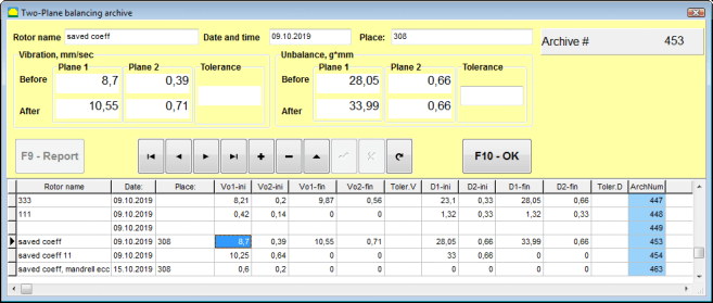
Fig. 7.32 Two plane balancing archive window.
ในหน้าต่างนี้ คุณต้องป้อนข้อมูลของโรเตอร์ที่สมดุลแล้ว หลังจากกด ""F10-OK"เมื่อกดปุ่ม " จะมีหน้าต่างปรับสมดุลปรากฏขึ้น".
Balancing settings (2-plane)
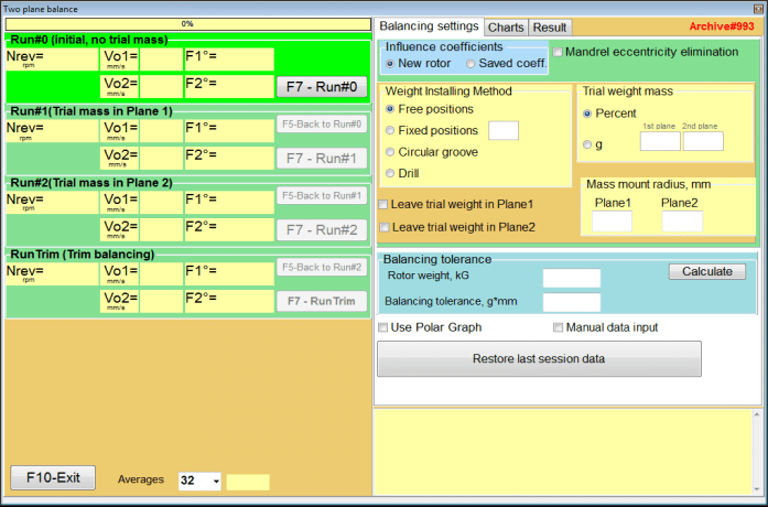
Fig. 7.33. Balancing in two planes window.
ด้านขวาของหน้าต่างคือ ""Balancing settings"แท็บสำหรับป้อนการตั้งค่าก่อนทำการปรับสมดุล.
- Influence coefficients - การปรับสมดุลใบพัดใหม่ หรือการปรับสมดุลโดยใช้ค่าสัมประสิทธิ์อิทธิพลที่บันทึกไว้ (ค่าสัมประสิทธิ์การปรับสมดุล)
- Mandrel eccentricity elimination - การปรับสมดุลด้วยการเริ่มต้นเพิ่มเติมเพื่อขจัดอิทธิพลของความเยื้องศูนย์ของแกนหมุน
- Weight Attachment Method - การติดตั้งตุ้มถ่วงแก้ไขในตำแหน่งใดก็ได้บนเส้นรอบวงของใบพัดหรือในตำแหน่งคงที่ การคำนวณสำหรับการเจาะเมื่อต้องการถอดตุ้มถ่วงออก.
- "Free position"- สามารถติดตั้งตุ้มถ่วงน้ำหนักในตำแหน่งเชิงมุมใดๆ บนเส้นรอบวงของใบพัดได้.
- "Fixed position"- สามารถติดตั้งตุ้มน้ำหนักในตำแหน่งเชิงมุมคงที่บนใบพัดได้ เช่น บนใบพัดหรือรู (เช่น 12 รู – 30 องศา) เป็นต้น ต้องป้อนจำนวนตำแหน่งคงที่ในช่องที่เหมาะสม หลังจากปรับสมดุลแล้ว โปรแกรมจะแบ่งตุ้มน้ำหนักออกเป็นสองส่วนโดยอัตโนมัติ และระบุจำนวนตำแหน่งที่จำเป็นต้องติดตั้งตุ้มน้ำหนักที่ได้มา.
- Trial weight mass - น้ำหนักทดลอง
- Leave trial weight in Plane1 / Plane2 - ถอดหรือใส่ตุ้มน้ำหนักทดลองเมื่อทำการปรับสมดุล.
- Mass mount radius, mm - รัศมีของการติดตั้งอุปกรณ์ทดสอบและตุ้มน้ำหนักปรับแก้
- Balancing tolerance - การป้อนหรือคำนวณค่าความคลาดเคลื่อนของความไม่สมดุลที่เหลืออยู่เป็นหน่วย g-mm
- Use Polar Graph - ใช้กราฟเชิงขั้วเพื่อแสดงผลลัพธ์การปรับสมดุล
- Manual data input - การป้อนข้อมูลด้วยตนเองเพื่อคำนวณน้ำหนักสมดุล
- Restore last session data - กู้คืนข้อมูลการวัดของรอบสุดท้ายในกรณีที่การปรับสมดุลไม่สำเร็จ.
2 planes balancing. New rotor
การตั้งค่าระบบการวัด (การป้อนข้อมูลเริ่มต้น)
Input of the initial data for the New rotor balancing ใน ""การปรับสมดุลสองระนาบ การตั้งค่า".
ในกรณีนี้ ใน ""Influence coefficients"ส่วน " ให้เลือก ""New rotor"" รายการ.
นอกจากนี้ ในส่วน ""Trial weight mass""คุณต้องเลือกหน่วยวัดมวลของน้ำหนักทดลอง - ""Gram"" หรือ ""Percent".
เมื่อเลือกหน่วยวัด ""Percent""การคำนวณมวลของตุ้มน้ำหนักแก้ไขทั้งหมดต่อไปนี้จะดำเนินการโดยคิดเป็นเปอร์เซ็นต์เทียบกับมวลของตุ้มน้ำหนักทดลอง".
เมื่อเลือก ""Gram""หน่วยวัด การคำนวณมวลของตุ้มน้ำหนักแก้ไขทั้งหมดต่อไปนี้จะดำเนินการในหน่วยกรัม จากนั้นป้อนในช่องที่อยู่ทางด้านขวาของข้อความ ""Gram""มวลของตุ้มน้ำหนักทดลองที่จะติดตั้งบนโรเตอร์".
⚠️ โปรดทราบ! หากจำเป็นต้องใช้ ""Saved coeff.""โหมดสำหรับการทำงานเพิ่มเติมในระหว่างการปรับสมดุลเบื้องต้น ต้องป้อนมวลของตุ้มน้ำหนักทดลองลงไป" grams.
จากนั้นเลือก ""Weight Attachment Method" - "Circum"" หรือ ""Fixed position".
หากคุณเลือก ""Fixed position"คุณต้องระบุจำนวนตำแหน่ง.
Calculation of tolerance for residual imbalance (Balancing tolerance)
ความคลาดเคลื่อนของความไม่สมดุลตกค้าง (ความคลาดเคลื่อนของการปรับสมดุล) สามารถคำนวณได้ตามขั้นตอนที่อธิบายไว้ใน ISO 1940 Vibration ข้อกำหนดด้านคุณภาพของเครื่องชั่งสำหรับโรเตอร์ในสภาวะคงที่ (แข็ง) ส่วนที่ 1 ข้อกำหนดและการตรวจสอบความคลาดเคลื่อนของเครื่องชั่ง

Fig. 7.34. Balancing tolerance calculation window
Initial run (Run#0)
เมื่อทรงตัวในระนาบสองระนาบใน ""New rotor"ในโหมด "การปรับสมดุล ต้องใช้การสอบเทียบสามครั้ง และการทดสอบเครื่องปรับสมดุลอย่างน้อยหนึ่งครั้ง".
การวัดการสั่นสะเทือนเมื่อเริ่มเดินเครื่องครั้งแรกจะดำเนินการใน ""Two plane balance"หน้าต่างการทำงานใน ""Run#0"" ส่วน.
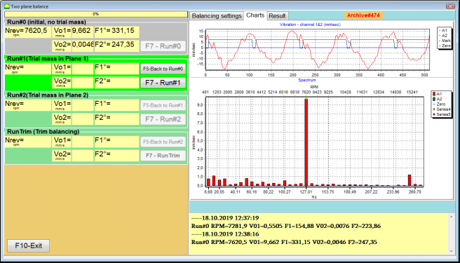
รูปที่ 7.35 ผลการวัดเมื่อทำการปรับสมดุลใน 2 ระนาบหลังการทำงานเริ่มต้น
⚠️ โปรดทราบ! ก่อนที่จะเริ่มการวัด จำเป็นต้องเปิดการหมุนของโรเตอร์ของเครื่องปรับสมดุล (การทำงานครั้งแรก) และตรวจสอบให้แน่ใจว่าเครื่องได้เข้าสู่โหมดการทำงานด้วยความเร็วที่เสถียร
To measure vibration parameters in the Run#0 ในส่วนนี้ ให้คลิกที่ ""F7 – Run#0"กดปุ่ม (หรือกดปุ่ม F7 บนแป้นพิมพ์คอมพิวเตอร์)
ผลลัพธ์ของการวัดความเร็วโรเตอร์ (RPM) ค่า RMS (VО1, VО2) และเฟส (F1, F2) ของการสั่นสะเทือน 1x ปรากฏในหน้าต่างที่สอดคล้องกันของ Run#0 section.
Run#1.Trial mass in Plane1
ก่อนเริ่มทำการวัดพารามิเตอร์การสั่นสะเทือนใน ""Run#1.Trial mass in Plane1"ในส่วน " คุณควรหยุดการหมุนของโรเตอร์ของเครื่องปรับสมดุล และติดตั้งตุ้มน้ำหนักทดสอบลงบนนั้น โดยเลือกมวลใน ""Trial weight mass"" ส่วน.
⚠️ โปรดทราบ!
- คำถามเกี่ยวกับการเลือกมวลของน้ำหนักทดลองและสถานที่ติดตั้งบนโรเตอร์ของเครื่องปรับสมดุลนั้นมีการอภิปรายอย่างละเอียดในภาคผนวก 1
- หากมีความจำเป็นต้องใช้ Saved coeff. Mode in future work, the place for installing the trial weight must necessarily coincide with the place for installing the mark used to read the phase angle.
After this, it is necessary to turn on the rotation of the rotor of the balancing machine again and make sure that it has entered the operating mode.
เพื่อวัดค่าพารามิเตอร์การสั่นสะเทือนใน ""Run # 1.Trial mass in Plane1"ส่วน " คลิกที่ ""F7 – Run#1"กดปุ่ม " (หรือกดปุ่ม F7 บนแป้นพิมพ์คอมพิวเตอร์).
เมื่อเสร็จสิ้นกระบวนการวัดผลสำเร็จ คุณจะกลับไปที่แท็บผลการวัด
ในกรณีนี้ ในหน้าต่างที่เกี่ยวข้องของ ""Run#1. Trial mass in Plane1""ส่วนนี้แสดงผลการวัดความเร็วรอบของโรเตอร์ (RPM) รวมถึงค่าของส่วนประกอบ RMS (Vо1, Vо2) และเฟส (F1, F2) ของการสั่นสะเทือน 1x".
""รัน # 2. มวลทดลองในระนาบ 2""
ก่อนเริ่มทำการวัดค่าพารามิเตอร์การสั่นสะเทือนในส่วน ""Run # 2.Trial mass in Plane2"คุณต้องดำเนินการตามขั้นตอนต่อไปนี้:
- หยุดการหมุนของโรเตอร์ของเครื่องสมดุล;
- ถอดน้ำหนักทดลองที่ติดตั้งในระนาบที่ 1 ออก
- ติดตั้งตุ้มน้ำหนักทดลองในระนาบที่ 2 โดยใช้มวลที่เลือกไว้ในส่วน ""Trial weight mass".
After this, turn on the rotation of the rotor of the balancing machine and make sure that it has entered the operating speed.
เพื่อเริ่มต้นการวัดการสั่นสะเทือนใน ""Run # 2.Trial mass in Plane2"ส่วน " คลิกที่ ""F7 – Run # 2"ปุ่ม " (หรือกดปุ่ม F7 บนแป้นพิมพ์คอมพิวเตอร์) จากนั้น ""Result""แท็บเปิดขึ้น".
In the case of using the Weight Attachment Method" - "Free positionsจอแสดงผลจะแสดงค่ามวล (M1, M2) และมุมการติดตั้ง (f1, f2) ของน้ำหนักแก้ไข
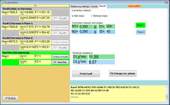
Fig. 7.36. Results of calculation of corrective weights – free position
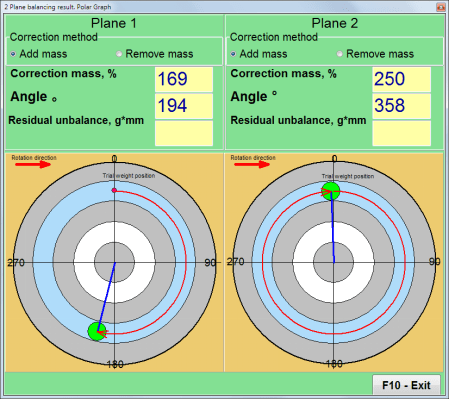
รูปที่ 7.37 ผลการคำนวณน้ำหนักแก้ไข – ตำแหน่งอิสระ แผนภาพเชิงขั้ว
In the case of using the Weight Attachment Method" – "Fixed positions

รูปที่ 7.38 ผลการคำนวณน้ำหนักแก้ไขตำแหน่งคงที่
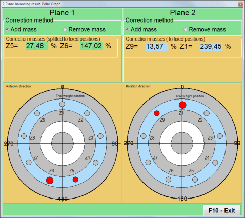
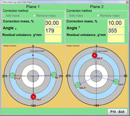
รูปที่ 7.39 ผลการคำนวณน้ำหนักแก้ไขตำแหน่งคงที่ แผนภาพเชิงขั้ว
ในกรณีที่ใช้วิธีการติดตั้งน้ำหนักถ่วง" – ""Circular groove"
รูปที่ 7.40 ผลการคำนวณน้ำหนักแก้ไข – ร่องวงกลม
⚠️ โปรดทราบ!
- หลังจากเสร็จสิ้นกระบวนการวัดบน RUN#2 of the balancing machine, stop the rotation of the rotor and remove the trial weight previously installed. Then you can to install (or remove) corrective weights.
- ตำแหน่งเชิงมุมของน้ำหนักแก้ไขในระบบพิกัดเชิงขั้วจะนับจากตำแหน่งการติดตั้งน้ำหนักทดลองในทิศทางการหมุนของโรเตอร์
- ในกรณีของ ""Fixed position"" - 1st position (Z1), coincides with the place of installation of the trial weight. The counting direction of the position number is in the direction of rotation of the rotor.
- โดยค่าเริ่มต้น น้ำหนักปรับแก้จะถูกเพิ่มเข้าไปในโรเตอร์ ซึ่งระบุไว้ด้วยป้ายกำกับที่ตั้งไว้ใน ""Add"ช่อง " หากต้องการลดน้ำหนัก (เช่น โดยการเจาะ) คุณต้องทำเครื่องหมายในช่อง ""Delete""ฟิลด์ดังกล่าว หลังจากนั้นตำแหน่งเชิงมุมของตุ้มน้ำหนักปรับแก้จะเปลี่ยนไปโดยอัตโนมัติ 180º".
RunC (Trim run)
After installing the correction weight on the balancing rotor it is necessary to carry out a RunC (trim) and evaluate the effectiveness of the performed balancing.
⚠️ โปรดทราบ! ก่อนที่จะเริ่มการวัดในระหว่างการทดสอบ จำเป็นต้องเปิดการหมุนของโรเตอร์ของเครื่องและตรวจสอบให้แน่ใจว่าได้เข้าสู่ความเร็วในการทำงานแล้ว
ในการวัดค่าพารามิเตอร์การสั่นสะเทือนในส่วน RunTrim (ตรวจสอบคุณภาพการทรงตัว) ให้คลิกที่ ""F7 – RunTrim"กดปุ่ม " (หรือกดปุ่ม F7 บนแป้นพิมพ์คอมพิวเตอร์).
The results of measuring the rotor rotation frequency (RPM), as well as the value of the RMS component (Vо1) and phase (F1) of 1x vibration will be shown.
""Result"แท็บ "จะปรากฏทางด้านขวาของหน้าต่างการทำงาน พร้อมตารางผลการวัด ซึ่งแสดงผลการคำนวณพารามิเตอร์ของน้ำหนักปรับแก้เพิ่มเติม".
These weights can be added to corrective weights that are already installed on the rotor to compensate for residual imbalance.
In addition, the residual rotor unbalance achieved after balancing is displayed in the lower part of this window.
ในกรณีที่ค่าการสั่นสะเทือนที่เหลือและ/หรือความไม่สมดุลที่เหลือของโรเตอร์ที่สมดุลตรงตามข้อกำหนดความคลาดเคลื่อนที่กำหนดไว้ในเอกสารทางเทคนิค กระบวนการปรับสมดุลก็จะเสร็จสมบูรณ์
Otherwise, the balancing process may continue. This allows the method of successive approximations to correct possible errors that may occur during the installation (removal) of the corrective weight on a balanced rotor.
เมื่อดำเนินการปรับสมดุลต่อบนโรเตอร์ปรับสมดุล จำเป็นต้องติดตั้ง (หรือถอด) มวลแก้ไขเพิ่มเติม ซึ่งพารามิเตอร์ของมวลแก้ไขนั้นระบุไว้ในหน้าต่าง "ผลลัพธ์".
ใน ""Result""หน้าต่างนี้มีปุ่มควบคุมสองปุ่มที่สามารถใช้งานได้ -""F4-Inf.Coeff", "F5 – Change correction planes".
Influence coefficients (2 planes)
""F4-Inf.Coeff"ปุ่ม "F4" (หรือปุ่มฟังก์ชัน F4 บนแป้นพิมพ์คอมพิวเตอร์) ใช้สำหรับดูและบันทึกค่าสัมประสิทธิ์การปรับสมดุลโรเตอร์ลงในหน่วยความจำคอมพิวเตอร์ ซึ่งคำนวณจากผลลัพธ์ของการเริ่มต้นการสอบเทียบสองครั้ง.
เมื่อกดแล้ว ""Influence coefficients (two planes)"หน้าต่างการทำงานจะปรากฏบนหน้าจอคอมพิวเตอร์ โดยจะแสดงค่าสัมประสิทธิ์การปรับสมดุลที่คำนวณจากผลลัพธ์ของการเริ่มต้นการสอบเทียบสามครั้งแรก.

Fig. 7.41. Working window with balancing coefficients in 2 planes.
ในอนาคต เมื่อทำการปรับสมดุลเครื่องจักรประเภทนี้ คาดว่าจะต้องใช้ ""Saved coeff.""ค่าโหมดและสัมประสิทธิ์การปรับสมดุลจะถูกจัดเก็บไว้ในหน่วยความจำคอมพิวเตอร์".
หากต้องการบันทึกค่าสัมประสิทธิ์ ให้คลิก ""F9 – Save"ปุ่ม " และไปที่ ""Influence coefficients archive (2planes)"หน้าต่าง (ดูรูปที่ 7.42)
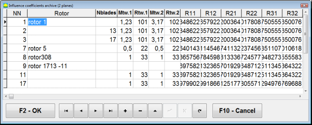
Fig. 7.42. The second page of the working window with balancing coefficients in 2 planes.
Change correction planes
""F5 – Change correction planes"ปุ่มนี้ใช้เมื่อต้องการเปลี่ยนตำแหน่งของระนาบแก้ไข เมื่อจำเป็นต้องคำนวณมวลและมุมการติดตั้งของน้ำหนักแก้ไขใหม่.
This mode is primarily useful when balancing rotors of complex shape (for example, crankshafts).
เมื่อกดปุ่มนี้ หน้าต่างการทำงาน ""Recalculation of correction weights mass and angle to other correction planes"" จะปรากฏบนหน้าจอคอมพิวเตอร์.
In this working window, you should select one of the 4 possible options by clicking corresponding picture.
ระนาบการแก้ไขดั้งเดิม (Н1 และ Н2) จะถูกทำเครื่องหมายด้วยสีเขียว และระนาบการแก้ไขใหม่ (K1 และ K2) ที่มีการนับใหม่ จะถูกทำเครื่องหมายด้วยสีแดง
จากนั้น ใน ""Calculation data"ในส่วน "ป้อนข้อมูลที่ร้องขอ รวมถึง:
- ระยะห่างระหว่างระนาบการแก้ไขที่สอดคล้องกัน (a, b, c)
- ค่าใหม่ของรัศมีในการติดตั้งตุ้มถ่วงปรับแก้บนโรเตอร์ (R1', R2').
หลังจากป้อนข้อมูลแล้ว คุณต้องกดปุ่ม ""F9-calculate"
ผลลัพธ์การคำนวณ (มวล M1, M2 และมุมการติดตั้งของน้ำหนักแก้ไข f1, f2) จะปรากฏในส่วนที่เกี่ยวข้องของหน้าต่างการทำงานนี้
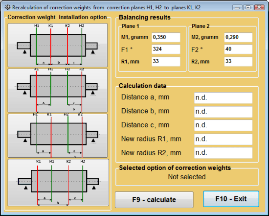
รูปที่ 7.43 เปลี่ยนระนาบแก้ไข คำนวณมวลและมุมแก้ไขใหม่ไปยังระนาบแก้ไขอื่น
บันทึกค่าสัมประสิทธิ์สมดุลใน 2 ระนาบ
Saved coeff. balancing can be performed on a machine for which balancing coefficients have already been determined and saved in the computer memory.
⚠️ โปรดทราบ! When re-balancing, the vibration sensors and the phase angle sensor must be installed in the same way as during the initial balancing.
การป้อนข้อมูลเริ่มต้นสำหรับการปรับสมดุลจะเริ่มใน ""สมดุลสองระนาบ การตั้งค่าสมดุล".
ในกรณีนี้ ใน ""Influence coefficients"ส่วน " ให้เลือก ""Saved coeff.""รายการ ในกรณีนี้คือหน้าต่าง""Influence coefficients archive (2planes)""จะปรากฏขึ้น ซึ่งเป็นที่เก็บไฟล์ข้อมูลของค่าสัมประสิทธิ์การปรับสมดุลที่กำหนดไว้ก่อนหน้านี้".
การเลื่อนดูตารางในคลังข้อมูลนี้โดยใช้ปุ่มควบคุม "►" หรือ "◄" คุณสามารถเลือกบันทึกที่ต้องการพร้อมค่าสัมประสิทธิ์การปรับสมดุลของเครื่องจักรที่เราสนใจได้ จากนั้น หากต้องการใช้ข้อมูลนี้ในการวัดปัจจุบัน ให้กดปุ่ม ""F2 – OK"ปุ่ม " เพื่อกลับไปยังหน้าต่างการทำงานก่อนหน้า".
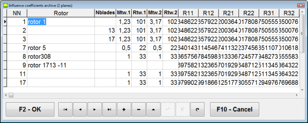
Fig. 7.44. The second page of the working window with balancing coefficients in 2 planes.
หลังจากนั้น เนื้อหาของหน้าต่างอื่นๆ ทั้งหมดของ ""การปรับสมดุลใน 2 pl. แหล่งข้อมูล"เครื่องหมาย " จะถูกกรอกโดยอัตโนมัติ.
Saved coeff. Balancing
"Saved coeff.""การปรับสมดุลต้องใช้การเริ่มต้นการปรับแต่งเพียงครั้งเดียว และการเริ่มต้นทดสอบเครื่องปรับสมดุลอย่างน้อยหนึ่งครั้ง".
Vibration measurement at the tuning start (Run # 0) ของเครื่องจักรจะดำเนินการใน ""Balancing in 2 planes"หน้าต่างการทำงานพร้อมตารางแสดงผลลัพธ์การปรับสมดุลใน Run # 0 section.
⚠️ โปรดทราบ! Before starting the measurement, it is necessary to turn on the rotation of the rotor of the balancing machine and make sure that it has entered the operating mode with a stable speed.
To measure vibration parameters in the Run # 0 ในส่วนนี้ ให้คลิกที่ ""F7 – Run#0"กดปุ่ม " (หรือกดปุ่ม F7 บนแป้นพิมพ์คอมพิวเตอร์).
The results of measuring the rotor speed (RPM), as well as the value of the components of the RMS (VО1, VО2) and phases (F1, F2) of the 1x vibration appear in the corresponding fields of the Run # 0 section.
ในขณะเดียวกัน ""Result"แท็บ "เปิดขึ้น" ซึ่งแสดงผลลัพธ์ของการคำนวณพารามิเตอร์ของตุ้มน้ำหนักปรับแก้ที่ต้องติดตั้งบนโรเตอร์เพื่อชดเชยความไม่สมดุล.
นอกจากนี้ ในกรณีที่ใช้ระบบพิกัดเชิงขั้ว จอภาพจะแสดงค่ามวลและมุมการติดตั้งของน้ำหนักแก้ไข
In the case of decomposition of corrective weights on the blades, the numbers of the blades of the balancing rotor and the mass of weight that need to be installed on them are displayed.
Further, the balancing process is carried out in accordance with the recommendations set out in section 7.6.1.2. for primary balancing.
⚠️ โปรดทราบ!
- After completion of the measurement process after the second start of the balanced machine stop the rotation of its rotor and remove the previously set trial weight. Only then you can begin to install (or remove) correction weight on the rotor.
- Counting the angular position of the place of adding (or removing) of the correction weight from the rotor is carried out on the installation site of trial weight in the polar coordinate system. Counting direction coincides with the direction of the angle of rotor rotation.
- ในกรณีที่มีการถ่วงดุลใบพัด ใบพัดโรเตอร์ที่สมดุล ซึ่งกำหนดไว้ที่ตำแหน่ง 1 จะตรงกับตำแหน่งที่ติดตั้งตุ้มน้ำหนักทดลอง หมายเลขอ้างอิงของใบพัดที่แสดงบนจอแสดงผลคอมพิวเตอร์จะชี้ไปในทิศทางการหมุนของโรเตอร์
- ในโปรแกรมเวอร์ชันนี้ ระบบจะยอมรับโดยค่าเริ่มต้นว่าน้ำหนักปรับแก้จะถูกเพิ่มเข้าไปในโรเตอร์ แท็กที่กำหนดไว้ในช่อง "การเพิ่ม" จะยืนยันการตั้งค่านี้ ในกรณีที่ต้องการแก้ไขความไม่สมดุลโดยการถอดน้ำหนักออก (เช่น โดยการเจาะ) จำเป็นต้องกำหนดแท็กในช่อง "การถอด" จากนั้นตำแหน่งเชิงมุมของน้ำหนักปรับแก้จะเปลี่ยนไปโดยอัตโนมัติ 180º.
การกำจัดความเยื้องศูนย์ของแกนหมุน (การปรับสมดุลดัชนี) - สองระนาบ
If during balancing the rotor is installed in a cylindrical mandrel, then the eccentricity of the mandrel may introduce an additional error. To eliminate this error, the rotor should be deployed in the mandrel 180 degrees and carry out an additional start. This is called index balancing.
To carry out index balancing, a special option is provided in the Balanset-1A program. When checked Mandrel eccentricity elimination an additional RunEcc section appears in the balancing window.
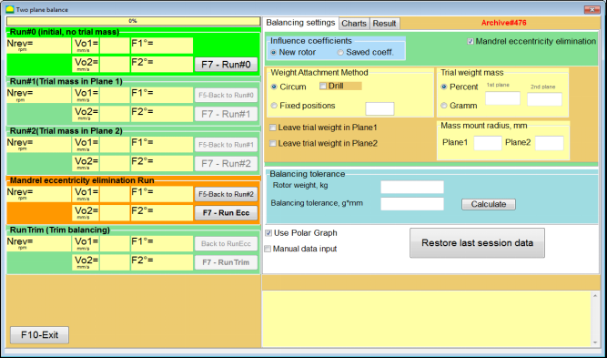
Fig. 7.45. The working window for Index balancing.
After running Run # 2 (Trial mass Plane 2), a window will appear
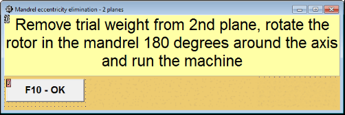
Fig. 7.46. Attention windows
หลังจากติดตั้งโรเตอร์ด้วยการหมุน 180° แล้ว จะต้องดำเนินการ Run Ecc ให้เสร็จสมบูรณ์ โปรแกรมจะคำนวณความไม่สมดุลที่แท้จริงของโรเตอร์โดยอัตโนมัติโดยไม่กระทบต่อความเยื้องศูนย์ของแกนหมุน
7.6 โหมดแผนภูมิ
การทำงานในโหมด "แผนภูมิ" เริ่มต้นจากหน้าต่างเริ่มต้น (ดูรูปที่ 7.1) โดยการกด ""F8 – แผนภูมิ" จากนั้นจะเปิดหน้าต่าง "การวัดการสั่นสะเทือนบนสองช่องสัญญาณ แผนภูมิ" (ดูรูปที่ 7.19).

รูปที่ 7.47 หน้าต่างการทำงาน "การวัดการสั่นสะเทือนบนสองช่องสัญญาณ แผนภูมิ".
While working in this mode it is possible to plot four versions of vibration chart.
The first version allows to get a timeline function of the overall vibration (of vibration velocity) on the first and second measuring channels.
The second version allows you to get graphs of vibration (of vibration velocity), which occurs on rotation frequency and its higher harmonical components.
These graphs are obtained as a result of the synchronous filtering of the overall vibration time function.
The third version provides vibration charts with the results of the harmonical analysis.
The fourth version allows to get a vibration chart with the results of the spectrum analysis.
แผนภูมิการสั่นสะเทือนโดยรวม
เพื่อสร้างแผนภูมิแสดงการสั่นสะเทือนโดยรวมในช่วงการทำงาน ""Measurement of vibration on two channels. Charts""จำเป็นต้องเลือกโหมดการทำงาน""overall vibration"โดยคลิกปุ่มที่เหมาะสม จากนั้นตั้งค่าการวัดการสั่นสะเทือนในช่อง "ระยะเวลา หน่วยเป็นวินาที" โดยคลิกปุ่ม "▼" และเลือกช่วงเวลาที่ต้องการวัดจากรายการแบบดรอปดาวน์ ซึ่งอาจเท่ากับ 1, 5, 10, 15 หรือ 20 วินาที;
เมื่อพร้อมแล้วให้กด (คลิก) ""F9-กดปุ่ม "วัด" จากนั้นกระบวนการวัดการสั่นสะเทือนจะเริ่มต้นพร้อมกันในสองช่องสัญญาณ.
After completion of the measurement process in the operating window appear charts of time function of the overall vibration of the first (red) and the second (green) channels (see. Fig. 7.47).
On these charts time is plotted on X-axis and the amplitude of the vibration velocity (mm/sec) is plotted on Y-axis.
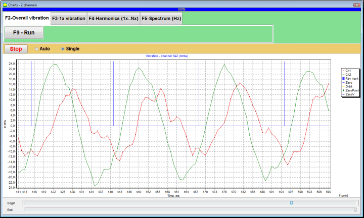
รูปที่ 7.48 หน้าต่างการทำงานสำหรับเอาต์พุตของฟังก์ชันเวลาของแผนภูมิการสั่นสะเทือนโดยรวม
There are also marks (blue-colored) in these graphs connecting charts of overall vibration with the rotation frequency of the rotor. In addition, each mark indicates beginning (end) of the next revolution of the rotor.
In need of the scale change of the chart on X-axis the slider, pointed by an arrow on fig. 7.20, can be used.
แผนภูมิการสั่นสะเทือน 1x
เพื่อสร้างแผนภูมิการสั่นสะเทือน 1x ในหน้าต่างการทำงาน ""Measurement of vibration on two channels. Charts""จำเป็นต้องเลือกโหมดการทำงาน""1x vibration"โดยการคลิกปุ่มที่เหมาะสม.
จากนั้นจะปรากฏหน้าต่างการทำงาน "การสั่นสะเทือน 1 เท่า".
กด (คลิก) ""F9-กดปุ่ม "วัด" จากนั้นกระบวนการวัดการสั่นสะเทือนจะเริ่มต้นพร้อมกันในสองช่องสัญญาณ.
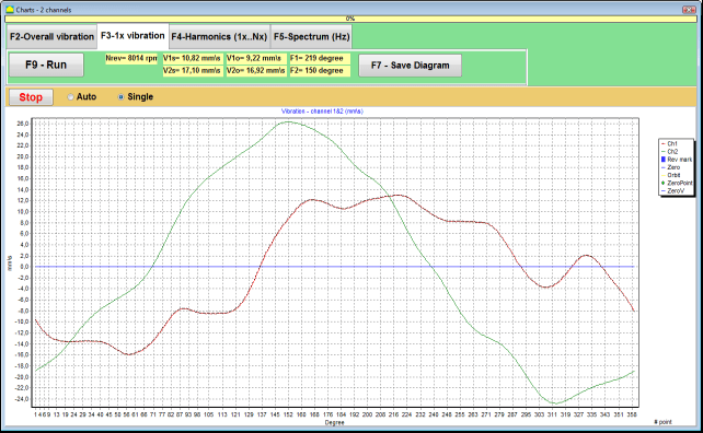
รูปที่ 7.49 หน้าต่างการทำงานสำหรับเอาต์พุตของแผนภูมิการสั่นสะเทือน 1x
After completion of the measurement process and mathematical calculation of results (synchronous filtering of the time function of the overall vibration) on display in the main window on a period equal to one revolution of the rotor appear charts of the 1x vibration on two channels.
In this case, a chart for the first channel is depicted in red and for the second channel in green. On these charts angle of the rotor revolution is plotted (from mark to mark) on X-axis and the amplitude of the vibration velocity (mm/sec) is plotted on Y-axis.
นอกจากนี้ ในส่วนบนของหน้าต่างการทำงาน (ทางด้านขวาของปุ่ม ""F9 – วัด"") ค่าตัวเลขของการวัดการสั่นสะเทือนของทั้งสองช่องสัญญาณ คล้ายกับค่าที่เราได้รับใน ""Vibration meter"โหมด " จะถูกแสดง.
In particular: RMS value of the overall vibration (V1s, V2s), the magnitude of RMS (V1o, V2o) and phase (Fi, Fj) of the 1x vibration and rotor speed (Nrev).
แผนภูมิการสั่นสะเทือนพร้อมผลการวิเคราะห์ฮาร์มอนิก
เพื่อสร้างแผนภูมิแสดงผลลัพธ์ของการวิเคราะห์ฮาร์มอนิกในช่วงการทำงาน ""Measurement of vibration on two channels. Charts""จำเป็นต้องเลือกโหมดการทำงาน""Harmonical analysis"โดยการคลิกปุ่มที่เหมาะสม.
จากนั้นจะปรากฏหน้าต่างการทำงานสำหรับการส่งออกแผนภูมิฟังก์ชันชั่วคราวและสเปกตรัมของลักษณะฮาร์มอนิกของการสั่นสะเทือนที่มีคาบเท่ากับหรือคูณกับความถี่การหมุนของโรเตอร์พร้อมกัน
Attention!
When operating in this mode it is necessary to use the phase angle sensor which synchronizes the measurement process with the rotor frequency of the machines to which the sensor is set.
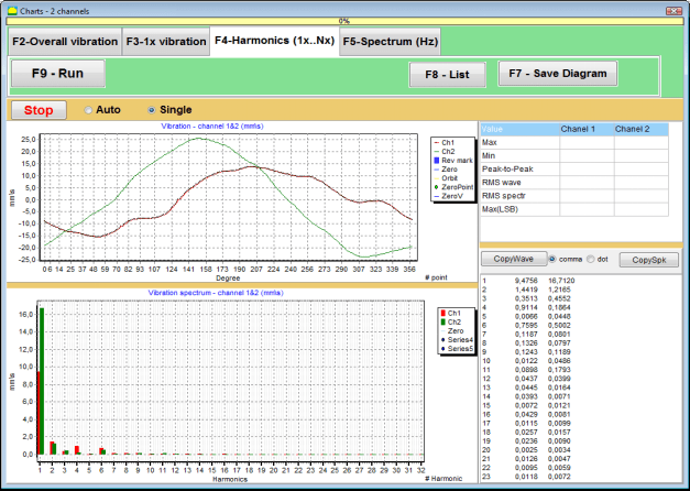
รูปที่ 7.50 ฮาร์มอนิกของหน้าต่างการทำงานของการสั่นสะเทือน 1x
เมื่อพร้อมแล้วให้กด (คลิก) ""F9-กดปุ่ม "วัด" จากนั้นกระบวนการวัดการสั่นสะเทือนจะเริ่มต้นพร้อมกันในสองช่องสัญญาณ.
หลังจากเสร็จสิ้นกระบวนการวัดผล ในหน้าต่างการทำงานจะปรากฏแผนภูมิฟังก์ชันเวลา (แผนภูมิด้านบน) และฮาร์โมนิกส์ของการสั่นสะเทือน 1 เท่า (แผนภูมิด้านล่าง)
The number of harmonic components is plotted on X-axis and RMS of the vibration velocity (mm/sec) is plotted on Y-axis.
แผนภูมิโดเมนเวลาและสเปกตรัมการสั่นสะเทือน
ในการสร้างแผนภูมิสเปกตรัม ให้ใช้ ""F5-สเปกตรัม"แท็บ:
จากนั้นจะปรากฏหน้าต่างปฏิบัติการสำหรับการส่งออกแผนภูมิคลื่นและสเปกตรัมของการสั่นสะเทือนพร้อมกัน

รูปที่ 7.51 หน้าต่างการทำงานสำหรับเอาต์พุตของสเปกตรัมการสั่นสะเทือน
เมื่อพร้อมแล้วให้กด (คลิก) ""F9-กดปุ่ม "วัด" จากนั้นกระบวนการวัดการสั่นสะเทือนจะเริ่มต้นพร้อมกันในสองช่องสัญญาณ.
หลังจากเสร็จสิ้นกระบวนการวัดผล จะปรากฏแผนภูมิฟังก์ชันเวลา (แผนภูมิด้านบน) และสเปกตรัมของการสั่นสะเทือน (แผนภูมิด้านล่าง) ในหน้าต่างการทำงาน
The vibration frequency is plotted on X-axis and RMS of the vibration velocity (mm/sec) is plotted on Y-axis.
In this case, a chart for the first channel is depicted in red and for the second channel in green.
8. คำแนะนำทั่วไปเกี่ยวกับการใช้งานและการบำรุงรักษาอุปกรณ์
8.1 การสร้างสมดุลเกณฑ์คุณภาพ (มาตรฐาน ISO 2372)
คุณภาพของการถ่วงดุลสามารถประเมินได้โดยใช้ระดับการสั่นสะเทือนที่กำหนดโดยมาตรฐาน ISO 2372 ตารางด้านล่างแสดงระดับการสั่นสะเทือนที่ยอมรับได้สำหรับเครื่องจักรประเภทต่างๆ:
| คลาสเครื่องจักร | ดี (มม./วินาที RMS) |
ยอมรับได้ (มม./วินาที RMS) |
ยังยอมรับได้ (มม./วินาที RMS) |
ไม่สามารถยอมรับได้ (มม./วินาที RMS) |
|---|---|---|---|---|
| ชั้นประถมศึกษาปีที่ 1 เครื่องจักรขนาดเล็กบนฐานรากแข็ง (มอเตอร์สูงสุด 15 กิโลวัตต์) |
<0.7 | 0.7 - 1.8 | 1.8 - 4.5 | > 4.5 |
| ชั้นประถมศึกษาปีที่ 2 เครื่องจักรขนาดกลางไม่มีฐานราก (มอเตอร์ 15-75 กิโลวัตต์) กลไกขับเคลื่อนสูงสุด 300 กิโลวัตต์ |
< 1.1 | 1.1 - 2.8 | 2.8 - 7.1 | > 7.1 |
| ชั้นประถมศึกษาปีที่ 3 เครื่องจักรขนาดใหญ่บนฐานรากที่แข็งแกร่ง (อุปกรณ์ขนาดเกิน 300 กิโลวัตต์) |
<1.8 | 1.8 - 4.5 | 4.5 - 11 | > 11 |
| ชั้นประถมศึกษาปีที่ 4 เครื่องจักรขนาดใหญ่บนฐานน้ำหนักเบา (อุปกรณ์ขนาดเกิน 300 กิโลวัตต์) |
<2.8 | 2.8 - 7.1 | 7.1 - 18 | > 18 |
หมายเหตุ: ค่าเหล่านี้เป็นเพียงแนวทางสำหรับการประเมินคุณภาพการปรับสมดุล โปรดอ้างอิงข้อมูลจำเพาะของผู้ผลิตอุปกรณ์เฉพาะและมาตรฐานที่เกี่ยวข้องสำหรับการใช้งานของคุณเสมอ
8.2 ข้อกำหนดการบำรุงรักษา
🔧 การบำรุงรักษาเป็นประจำ
- ✓การสอบเทียบเซ็นเซอร์เป็นประจำตามข้อกำหนดของผู้ผลิต
- ✓รักษาเซ็นเซอร์ให้สะอาดและปราศจากเศษแม่เหล็ก
- ✓เก็บอุปกรณ์ในกล่องป้องกันเมื่อไม่ได้ใช้งาน
- ✓ปกป้องเซ็นเซอร์เลเซอร์จากฝุ่นและความชื้น
- ✓ตรวจสอบการเชื่อมต่อสายเคเบิลเป็นประจำเพื่อดูว่ามีการสึกหรอหรือเสียหายหรือไม่
- ✓อัปเดตซอฟต์แวร์ตามคำแนะนำของผู้ผลิต
- ✓รักษาสำเนาสำรองข้อมูลสมดุลที่สำคัญ
📋 มาตรฐานการบำรุงรักษาของสหภาพยุโรป
การบำรุงรักษาอุปกรณ์จะต้องเป็นไปตาม:
- เอ็นไอเอสโอ 9001: ข้อกำหนดระบบการจัดการคุณภาพ
- EN 13306: คำศัพท์และคำจำกัดความในการบำรุงรักษา
- EN 15341: ตัวชี้วัดประสิทธิภาพหลักในการบำรุงรักษา
- การตรวจสอบความปลอดภัยเป็นประจำตามคำสั่งเครื่องจักรของสหภาพยุโรป
ภาคผนวก 1. การปรับสมดุลโรเตอร์
โรเตอร์คือชิ้นส่วนที่หมุนรอบแกนใดแกนหนึ่งและยึดไว้ด้วยพื้นผิวรับน้ำหนักในตัวรองรับ พื้นผิวรับน้ำหนักของโรเตอร์จะส่งน้ำหนักไปยังตัวรองรับผ่านตลับลูกปืนแบบหมุนหรือแบบเลื่อน ในการใช้คำว่า "พื้นผิวรับน้ำหนัก" เรามักหมายถึงแกนหมุน* หรือพื้นผิวที่ใช้แทนแกนหมุน.
*เจอร์นัล (Zapfen ในภาษาเยอรมันแปลว่า "เจอร์นัล" หรือ "หมุด") - คือส่วนหนึ่งของเพลาหรือแกนที่ถูกยึดไว้ด้วยตัวยึด (กล่องแบริ่ง).
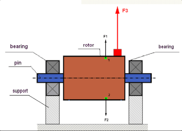
fig.1 Rotor and centrifugal forces.
In a perfectly balanced rotor, its mass is distributed symmetrically regarding the axis of the rotation. This means that any element of the rotor can correspond to another element located symmetrically in a relation to the axis of the rotation. During rotation, each rotor element acts upon by a centrifugal force directed in the radial direction (perpendicular to the axis of the rotor rotation). In a balanced rotor, the centrifugal force influencing any element of the rotor is balanced by the centrifugal force that influences the symmetrical element. For example, elements 1 and 2 (shown in fig.1 and colored in green) are influenced by centrifugal forces F1 and F2: equal in value and absolutely opposite in directions. This is true for all symmetrical elements of the rotor and thus the total centrifugal force influencing the rotor is equal to 0 the rotor is balanced. But if the symmetry of the rotor is broken (in Figure 1, the asymmetric element is marked in red), then the unbalanced centrifugal force F3 begins to act on the rotor.
เมื่อหมุน แรงนี้จะเปลี่ยนทิศทางไปพร้อมกับการหมุนของโรเตอร์ ภาระพลวัตที่เกิดจากแรงนี้จะถูกถ่ายโอนไปยังตลับลูกปืน ซึ่งนำไปสู่การสึกหรอที่เร็วขึ้น นอกจากนี้ ภายใต้อิทธิพลของแรงแปรผันนี้ ยังทำให้เกิดการเสียรูปเป็นวัฏจักรของส่วนรองรับและฐานรากที่โรเตอร์ยึดติดอยู่ ซึ่งก่อให้เกิดการสั่นสะเทือน เพื่อขจัดความไม่สมดุลของโรเตอร์และการสั่นสะเทือนที่เกิดขึ้น จำเป็นต้องปรับสมดุลมวลเพื่อคืนความสมมาตรของโรเตอร์
Rotor balancing is an operation to eliminate imbalance by adding balancing masses.
The task of balancing is to find the value and places (angle) of the installation of one or more balancing masses.
ประเภทของโรเตอร์และความไม่สมดุล
Considering the strength of the rotor material and the magnitude of the centrifugal forces influencing it, the rotors can be divided into two types: rigid and flexible.
โรเตอร์แบบแข็งภายใต้สภาวะการทำงานภายใต้อิทธิพลของแรงเหวี่ยงหนีศูนย์กลางอาจเกิดการเสียรูปเล็กน้อย แต่สามารถละเลยอิทธิพลของการเสียรูปนี้ในการคำนวณได้
Deformation of flexible rotors on the other hand should never be neglected. The deformation of flexible rotors complicates the solution for the balancing problem and requires the use of some other mathematical models in comparison with the task of balancing rigid rotors. It is important to mention that the same rotor at low speeds of rotation can behave like rigid one and at high speeds it will behave like flexible one. Further on we will consider the balancing of rigid rotors only.
ความไม่สมดุลสามารถแบ่งได้สองประเภทตามการกระจายตัวของมวลที่ไม่สมดุลตลอดความยาวของโรเตอร์ คือ ความไม่สมดุลแบบคงที่และแบบไดนามิก เช่นเดียวกับการปรับสมดุลโรเตอร์แบบคงที่และแบบไดนามิก
ความไม่สมดุลแบบสถิตของโรเตอร์เกิดขึ้นโดยที่โรเตอร์ไม่หมุน กล่าวคือ มันจะอยู่นิ่งเมื่อโรเตอร์อยู่ภายใต้แรงโน้มถ่วง และนอกจากนี้ยังทำให้ "จุดหนัก" เอียงลง ตัวอย่างของโรเตอร์ที่มีความไม่สมดุลแบบสถิตแสดงในรูปที่ 2

Fig.2
The dynamic imbalance occurs only when the rotor spins.
An example of a rotor with the dynamic imbalance is presented in Fig.3.
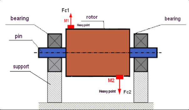
Fig.3. Dynamic imbalance of rotor – couple of the centrifugal forces
ในกรณีนี้ มวลเท่ากันที่ไม่สมดุล M1 และ M2 ตั้งอยู่บนพื้นผิวที่แตกต่างกัน – ในตำแหน่งที่แตกต่างกันตามความยาวของโรเตอร์ ในตำแหน่งคงที่ กล่าวคือเมื่อโรเตอร์ไม่หมุน โรเตอร์จะได้รับอิทธิพลจากแรงโน้มถ่วงเท่านั้น และมวลจึงจะสมดุลกัน ในขณะที่โรเตอร์กำลังหมุน มวล M1 และ M2 จะเริ่มได้รับอิทธิพลจากแรงเหวี่ยงหนีศูนย์กลาง FЎ1 และ FЎ2 แรงเหล่านี้มีค่าเท่ากันและมีทิศทางตรงกันข้าม อย่างไรก็ตาม เนื่องจากพวกมันตั้งอยู่ในตำแหน่งที่แตกต่างกันตามความยาวของเพลาและไม่ได้อยู่บนเส้นเดียวกัน แรงจึงไม่หักล้างกัน แรง FЎ1 และ FЎ2 สร้างโมเมนต์ที่กระทำต่อโรเตอร์ นั่นคือเหตุผลที่ความไม่สมดุลนี้มีชื่อเรียกอีกอย่างว่า "โมเมนต์" ดังนั้น แรงเหวี่ยงหนีศูนย์กลางที่ไม่ได้รับการหักล้างจะกระทำต่อตัวรองรับแบริ่ง ซึ่งอาจเกินแรงที่เราคาดการณ์ไว้มาก และยังลดอายุการใช้งานของแบริ่งอีกด้วย.
เนื่องจากความไม่สมดุลประเภทนี้เกิดขึ้นเฉพาะในระหว่างการหมุนของโรเตอร์เท่านั้น จึงเรียกว่าความไม่สมดุลแบบไดนามิก ไม่สามารถกำจัดได้ด้วยการปรับสมดุลแบบสถิต (หรือที่เรียกว่า "การปรับสมดุลบนใบมีด") หรือวิธีการอื่นใดที่คล้ายคลึงกัน ในการกำจัดความไม่สมดุลแบบไดนามิก จำเป็นต้องติดตั้งตุ้มน้ำหนักชดเชยสองตัวที่จะสร้างแรงบิดที่มีค่าเท่ากันและทิศทางตรงกันข้ามกับแรงบิดที่เกิดจากมวล M1 และ M2 มวลชดเชยไม่จำเป็นต้องติดตั้งตรงข้ามกับมวล M1 และ M2 และมีค่าเท่ากัน สิ่งสำคัญที่สุดคือต้องสร้างแรงบิดที่ชดเชยได้อย่างสมบูรณ์ ณ เวลาที่เกิดความไม่สมดุล.
โดยทั่วไป มวล M1 และ M2 อาจไม่เท่ากัน ดังนั้นจึงเกิดความไม่สมดุลทั้งแบบสถิตและแบบไดนามิก ตามทฤษฎีแล้ว การติดตั้งตุ้มน้ำหนักสองอันโดยเว้นระยะห่างตามความยาวของโรเตอร์ จะช่วยขจัดความไม่สมดุลของโรเตอร์ได้ ตุ้มน้ำหนักเหล่านี้จะชดเชยทั้งโมเมนต์ที่เกิดจากความไม่สมดุลแบบไดนามิกและแรงเหวี่ยงหนีศูนย์กลางที่เกิดจากความไม่สมมาตรของมวลเทียบกับแกนโรเตอร์ (ความไม่สมดุลแบบสถิต) โดยปกติแล้ว ความไม่สมดุลแบบไดนามิกมักเกิดขึ้นกับโรเตอร์ยาว เช่น เพลา และความไม่สมดุลแบบสถิตมักเกิดขึ้นกับโรเตอร์แคบ อย่างไรก็ตาม หากโรเตอร์แคบถูกติดตั้งเอียงเมื่อเทียบกับแกน หรือแย่กว่านั้นคือเสียรูป (ที่เรียกว่า "การสั่นของล้อ") ในกรณีนี้จะยากที่จะขจัดความไม่สมดุลแบบไดนามิก (ดูรูปที่ 4) เนื่องจากยากที่จะติดตั้งตุ้มน้ำหนักแก้ไขที่สร้างโมเมนต์ชดเชยที่ถูกต้อง.
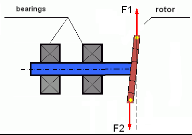
Fig.4 Dynamic balancing of the wobbling wheel
เนื่องจากส่วนไหล่ของใบพัดที่แคบทำให้เกิดแรงบิดสั้น จึงอาจต้องใช้ตุ้มถ่วงน้ำหนักขนาดใหญ่เพื่อปรับสมดุล แต่ในขณะเดียวกันก็เกิดสิ่งที่เรียกว่า "ความไม่สมดุลที่เกิดขึ้นโดยบังเอิญ" เพิ่มเติม ซึ่งเกี่ยวข้องกับการเสียรูปของใบพัดที่แคบภายใต้แรงเหวี่ยงหนีศูนย์กลางจากตุ้มถ่วงน้ำหนักเหล่านั้น.
See the example:
""คำแนะนำอย่างเป็นระบบเกี่ยวกับการปรับสมดุลโรเตอร์แบบแข็ง"" ISO 1940-1:2003 Mechanical vibration – Balance quality requirements for rotors in a constant (rigid) state – Part 1: Specification and verification of balance tolerances
This is visible for narrow fan wheels, which, in addition to the power imbalance, also influences an aerodynamic imbalance. And it is important to bear in mind that the aerodynamic imbalance, in fact the aerodynamic force, is directly proportional to the angular velocity of the rotor, and to compensate it, the centrifugal force of the correcting mass is used, which is proportional to the square of the angular velocity. Therefore, the balancing effect may only occur at a specific balancing frequency. At other speeds there would be an additional gap. The same can be said about electromagnetic forces in an electromagnetic motor, which are also proportional to the angular velocity. In other words it is impossible to eliminate all causes of vibration of the mechanism by any means of balancing.
พื้นฐานของการสั่นสะเทือน
การสั่นสะเทือนเป็นปฏิกิริยาของการออกแบบกลไกต่อผลของแรงกระตุ้นแบบวนซ้ำ แรงนี้อาจมีลักษณะที่แตกต่างกันออกไป
- แรงเหวี่ยงหนีศูนย์กลางที่เกิดขึ้นเนื่องจากความไม่สมดุลของโรเตอร์เป็นแรงที่ไม่ได้รับการชดเชยซึ่งส่งผลต่อ "จุดหนัก" โดยเฉพาะอย่างยิ่ง แรงนี้และแรงสั่นสะเทือนที่เกิดจากแรงนี้จะถูกกำจัดออกไปได้ด้วยการปรับสมดุลโรเตอร์.
- แรงปฏิกิริยาที่มีลักษณะ "ทางเรขาคณิต" และเกิดขึ้นจากข้อผิดพลาดในการผลิตและการติดตั้งชิ้นส่วนที่ประกบกัน แรงเหล่านี้อาจเกิดขึ้นได้ เช่น ความไม่กลมของแกนเพลา ข้อผิดพลาดในรูปทรงฟันเฟือง ความไม่เรียบของร่องลูกปืน การเยื้องศูนย์ของเพลาที่ประกบกัน เป็นต้น ในกรณีที่คอเพลาไม่กลม แกนเพลาจะเลื่อนไปตามมุมการหมุนของเพลา แม้ว่าการสั่นสะเทือนนี้จะปรากฏให้เห็นที่ความเร็วรอบของโรเตอร์ แต่ก็แทบเป็นไปไม่ได้เลยที่จะกำจัดมันด้วยการปรับสมดุล.
- Aerodynamic forces arising from the rotation of the impeller fans and other blade mechanisms. Hydrodynamic forces arising from the rotation of hydraulic pump impellers, turbines, etc.
- แรงแม่เหล็กไฟฟ้าที่เกิดจากการทำงานของเครื่องจักรไฟฟ้า อันเป็นผลจากความไม่สมมาตรของขดลวดโรเตอร์ การมีขดลวดลัดวงจร เป็นต้น
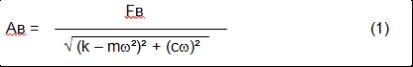
The magnitude of vibration (for example, its amplitude AB) depends not only on the magnitude of the excitation force Fт acting on the mechanism with the circular frequency ω, but also on the stiffness k of the structure of the mechanism, its mass m, and damping coefficient C.
Various types of sensors can be used to measure vibration and balance mechanisms, including:
- absolute vibration sensors designed to measure vibration acceleration (accelerometers) and vibration velocity sensors;
- เซ็นเซอร์วัดการสั่นสะเทือนแบบสัมพันธ์กันกระแสวนหรือแบบคาปาซิทีฟ ออกแบบมาเพื่อวัดการสั่นสะเทือน
In some cases (when the structure of the mechanism allows it) sensors of force can also be used to examine its vibration weight.
Particularly, they are widely used to measure the vibration weight of the supports of hardbearing balancing machines.
Therefore vibration is the reaction of the mechanism to the influence of external forces. The amount of vibration depends not only on the magnitude of the force acting on the mechanism, but also on the rigidity of the mechanism. Two forces with the same magnitude can lead to different vibrations. In mechanisms with a rigid support structure, even with the small vibration, the bearing units can be significantly influenced by dynamic weights. Therefore, when balancing mechanisms with stiff legs apply the force sensors, and vibration (vibro accelerometers). Vibration sensors are only used on mechanisms with relatively pliable supports, right when the action of unbalanced centrifugal forces leads to a noticeable deformation of the supports and vibration. Force sensors are used in rigid supports even when significant forces arising from imbalance do not lead to significant vibration.
ความสั่นพ้องของโครงสร้าง
We have previously mentioned that rotors are divided into rigid and flexible. The rigidity or flexibility of the rotor should not be confused with the stiffness or mobility of the supports (foundation) on which the rotor is located. The rotor is considered rigid when its deformation (bending) under the action of centrifugal forces can be neglected. The deformation of the flexible rotor is relatively large: it cannot be neglected.
ในบทความนี้ เราจะศึกษาเฉพาะการปรับสมดุลของโรเตอร์แบบแข็ง โรเตอร์แบบแข็ง (ไม่เสียรูป) ในทางกลับกันสามารถตั้งอยู่บนฐานรองรับแบบแข็งหรือแบบเคลื่อนที่ได้ (แบบอ่อน) ได้ เป็นที่ชัดเจนว่าความแข็ง/ความคล่องตัวของฐานรองรับนี้สัมพันธ์กันโดยขึ้นอยู่กับความเร็วรอบของโรเตอร์และขนาดของแรงเหวี่ยงหนีศูนย์กลางที่เกิดขึ้น ขอบทั่วไปคือความถี่ของการสั่นอิสระของฐานรองรับ/ฐานรากของโรเตอร์ สำหรับระบบเครื่องกล รูปร่างและความถี่ของการสั่นอิสระถูกกำหนดโดยมวลและความยืดหยุ่นขององค์ประกอบต่างๆ ในระบบเครื่องกล กล่าวคือ ความถี่ของการสั่นตามธรรมชาติเป็นลักษณะภายในของระบบเครื่องกลและไม่ขึ้นอยู่กับแรงภายนอก เมื่อฐานรองรับเบี่ยงเบนออกจากสภาวะสมดุล ฐานรองรับมักจะกลับสู่ตำแหน่งสมดุลเนื่องจากความยืดหยุ่น แต่เนื่องจากความเฉื่อยของโรเตอร์ขนาดใหญ่ กระบวนการนี้จึงมีลักษณะของการสั่นแบบหน่วง การสั่นเหล่านี้คือการสั่นของระบบโรเตอร์-ฐานรองรับ ความถี่ของมันขึ้นอยู่กับอัตราส่วนของมวลโรเตอร์และความยืดหยุ่นของตัวรองรับ
When the rotor begins to rotate and the frequency of its rotation approaches the frequency of its own oscillations, the vibration amplitude increases sharply, which can even lead to the destruction of the structure.
There is a phenomenon of mechanical resonance. In the resonance region, a change in the speed of rotation by 100 rpm can lead to an increase in a vibration tenfold. In this case (in the resonance region) the vibration phase changes by 180°.
หากการออกแบบกลไกไม่ดี และความเร็วในการทำงานของโรเตอร์ใกล้เคียงกับความถี่ธรรมชาติของการสั่น กลไกจะไม่สามารถทำงานได้เนื่องจากการสั่นสะเทือนสูงเกินไป วิธีการปรับสมดุลแบบมาตรฐานก็เป็นไปไม่ได้เช่นกัน เพราะพารามิเตอร์จะเปลี่ยนแปลงอย่างมากแม้ความเร็วในการหมุนจะเปลี่ยนแปลงเพียงเล็กน้อย จึงมีการใช้วิธีการพิเศษในด้านการปรับสมดุลแบบเรโซแนนซ์ แต่ไม่ได้อธิบายไว้ในบทความนี้อย่างละเอียด คุณสามารถตรวจสอบความถี่ของการสั่นตามธรรมชาติของกลไกได้ในขณะที่หยุดทำงาน (เมื่อโรเตอร์หยุดหมุน) หรือโดยการกระแทก แล้วทำการวิเคราะห์สเปกตรัมของการตอบสนองของระบบต่อแรงกระแทก เครื่องมือ "Balanset-1" ช่วยให้สามารถกำหนดความถี่ธรรมชาติของโครงสร้างทางกลโดยใช้วิธีการเหล่านี้ได้.
For mechanisms whose operating speed is higher than the resonance frequency, that is, operating in the resonant mode, supports are considered as mobile ones and vibration sensors are used to measure, mainly vibration accelerometers that measure the acceleration of structural elements. For mechanisms operating in hard bearing mode, supports are considered as rigid. In this case, force sensors are used.
แบบจำลองเชิงเส้นและไม่เชิงเส้นของระบบกลไก
Mathematical models (linear) are used for calculations when balancing rigid rotors. The linearity of the model means that one model is directly proportionally (linearly) dependent on the other. For example, if the uncompensated mass on the rotor is doubled, then the vibration value will be doubled correspondingly. For rigid rotors you can use a linear model because such rotors are not deformed. It is no longer possible to use a linear model for flexible rotors. For a flexible rotor, with an increase of the mass of a heavy point during rotation, an additional deformation will occur, and in addition to the mass, the radius of the heavy point will also increase. Therefore, for a flexible rotor, the vibration will more than double, and the usual calculation methods will not work. Also, a violation of the linearity of the model can lead to a change in the elasticity of the supports at their large deformations, for example, when small deformations of the supports work some structural elements, and when large in the work include other structural elements. Therefore it is impossible to balance the mechanisms that are not fixed at the base, and, for example, are simply established on a floor. With significant vibrations, the unbalance force can detach the mechanism from the floor, thereby significantly changing the stiffness characteristics of the system. The engine legs must be securely fastened, bolted fasteners tightened, the thickness of the washers must provide sufficient rigidity, etc. With broken bearings, a significant displacement of the shaft and its impacts is possible, which will also lead to a violation of linearity and the impossibility of carrying out high-quality balancing.
Methods and devices for balancing
As mentioned above, balancing is the process of combining the main Central axis of inertia with the axis of rotation of the rotor.
The specified process can be executed in two ways.
The first method involves the processing of the rotor axles, which is performed in such a way that the axis passing through the centers of the section of the axles with the main Central axis of inertia of the rotor. This technique is rarely used in practice and will not be discussed in detail in this article.
The second (most common) method involves moving, installing or removing corrective masses on the rotor, which are placed in such a way that the axis of inertia of the rotor is as close as possible to the axis of its rotation.
Moving, adding or removing corrective masses during balancing can be done using a variety of technological operations, including: drilling, milling, surfacing, welding, screwing or unscrewing screws, burning with a laser beam or electron beam, electrolysis, electromagnetic welding, etc.
The balancing process can be performed in two ways:
- ชุดโรเตอร์สมดุล (ในตลับลูกปืนของตัวเอง)
- การปรับสมดุลโรเตอร์บนเครื่องปรับสมดุล
To balance the rotors in their own bearings we usually use specialized balancing devices (kits), which allows us to measure the vibration of the balanced rotor at the speed of its rotation in a vector form, i.e. to measure both the amplitude and phase of vibration.
Currently, these devices are manufactured on the basis of microprocessor technology and (in addition to the measurement and analysis of vibration) provide automated calculation of the parameters of corrective weights that must be installed on the rotor to compensate its imbalance.
These devices include:
- หน่วยวัดและคำนวณที่สร้างขึ้นโดยใช้คอมพิวเตอร์หรือตัวควบคุมทางอุตสาหกรรม
- เซ็นเซอร์ตรวจจับการสั่นสะเทือน 2 ตัว (หรือมากกว่า)
- เซนเซอร์มุมเฟส;
- อุปกรณ์สำหรับติดตั้งเซ็นเซอร์ภายในโรงงาน;
- ซอฟต์แวร์เฉพาะทางที่ออกแบบมาเพื่อทำการวัดค่าพารามิเตอร์ความไม่สมดุลของโรเตอร์แบบครบรอบในระนาบแก้ไขหนึ่ง ระนาบสองระนาบหรือมากกว่า
สำหรับการปรับสมดุลโรเตอร์บนเครื่องปรับสมดุล นอกเหนือจากอุปกรณ์ปรับสมดุลเฉพาะทาง (ระบบวัดของเครื่องจักร) แล้ว ยังจำเป็นต้องมี "กลไกคลาย" ที่ออกแบบมาเพื่อติดตั้งโรเตอร์บนแท่นรองรับและรับประกันการหมุนด้วยความเร็วคงที่.
Currently, the most common balancing machines exist in two types:
- สั่นพ้องมากเกินไป (พร้อมตัวรองรับที่ยืดหยุ่น)
- การรับน้ำหนักที่แข็ง (โดยมีตัวรองรับที่แข็งแรง)
Over-resonant machines have a relatively pliable supports, made, for example, on the basis of the flat springs.
The natural oscillation frequency of these supports is usually 2-3 times lower than the speed of the balanced rotor, which is mounted on them.
Vibration sensors (accelerometers, vibration velocity sensors, etc.) are usually used to measure the vibration of the supports of a resonant machine.
In the hardbearing balancing machines are used relatively-rigid supports, natural oscillation frequencies of which should be 2-3 times higher than the speed of the balanced rotor.
Force sensors are usually used to measure the vibration weight on the supports of the machine.
The advantage of the hard bearing balancing machines is that they can be balanced at relatively low rotor speeds (up to 400-500 rpm), which greatly simplifies the design of the machine and its foundation, as well as increases the productivity and safety of balancing.
Balancing technique
⚠️ การปรับสมดุลจะช่วยขจัดเฉพาะการสั่นสะเทือนที่เกิดจากความไม่สมมาตรของการกระจายมวลของโรเตอร์เทียบกับแกนหมุนเท่านั้น การสั่นสะเทือนประเภทอื่นไม่สามารถขจัดได้ด้วยการปรับสมดุล!
Balancing is the subject to technically serviceable mechanisms, the design of which ensures the absence of resonances at the operating speed, securely fixed on the foundation, installed in serviceable bearings.
🚫 กลไกที่ชำรุดจะต้องได้รับการซ่อมแซมก่อน แล้วจึงทำการปรับสมดุล มิเช่นนั้น การปรับสมดุลที่มีคุณภาพจะเป็นไปไม่ได้.
Balancing cannot be a substitute for repair!
The main task of balancing is to find the mass and the place (angle) of installation of compensating weights, which are balanced by centrifugal forces.
As mentioned above, for rigid rotors it is generally necessary and sufficient to install two compensating weights. This will eliminate both the static and dynamic rotor imbalance. A general scheme of the vibration measurement during balancing looks like the following:
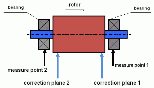
fig.5 Dynamic balancing – correction planes and measure points
Vibration sensors are installed on the bearing supports at points 1 and 2. The speed mark is fixed right on the rotor, a reflective tape is glued usually. The speed mark is used by the laser tachometer to determine the speed of the rotor and the phase of the vibration signal.
รูปที่ 6 การติดตั้งเซ็นเซอร์ระหว่างการปรับสมดุลในสองระนาบโดยใช้ Balanset-1
1,2-vibration sensors, 3-phase, 4- USB measuring unit, 5-laptop
In most cases, dynamic balancing is carried out by the method of three starts. This method is based on the fact that test weights of an already-known mass are installed on the rotor in series in 1 and 2 planes; so the masses and the place of installation of balancing weights are calculated based on the results of changing the vibration parameters.
ตำแหน่งติดตั้งตุ้มน้ำหนักเรียกว่าระนาบแก้ไข โดยทั่วไป ระนาบแก้ไขจะถูกเลือกในบริเวณที่รองรับตลับลูกปืนซึ่งโรเตอร์ติดตั้งอยู่
การสั่นสะเทือนเริ่มต้นจะถูกวัดในตอนเริ่มต้นครั้งแรก จากนั้นจะติดตั้งตุ้มน้ำหนักทดลองที่มีมวลที่ทราบค่าแล้วลงบนโรเตอร์ใกล้กับจุดรองรับด้านใดด้านหนึ่ง จากนั้นจะเริ่มต้นครั้งที่สอง และวัดค่าพารามิเตอร์การสั่นสะเทือนที่ควรเปลี่ยนแปลงเนื่องจากการติดตั้งตุ้มน้ำหนักทดลอง จากนั้นจะถอดตุ้มน้ำหนักทดลองในระนาบแรกออกและติดตั้งในระนาบที่สอง การเริ่มต้นครั้งที่สามจะวัดค่าพารามิเตอร์การสั่นสะเทือน เมื่อถอดตุ้มน้ำหนักทดลองออก โปรแกรมจะคำนวณมวลและตำแหน่ง (มุม) ของการติดตั้งตุ้มน้ำหนักถ่วงโดยอัตโนมัติ
The point in setting up test weights is to determine how the system responds to the imbalance change. When we know the masses and the location of the sample weights, the program can calculate the so-called influence coefficients, showing how the introduction of a known imbalance affects the vibration parameters. The coefficients of influence are the characteristics of the mechanical system itself and depend on the stiffness of the supports and the mass (inertia) of the rotor-support system.
For the same type of mechanisms of the same design, the coefficients of influence will be similar. You can save them in your computer memory and use them afterwards for balancing the same type of mechanisms without carrying out test runs, which greatly improves the performance of the balancing. We should also note that the mass of test weights should be chosen as such so that the vibration parameters vary markedly when installing test weights. Otherwise, the error in calculating the coefficients of the affect increases and the quality of balancing deteriorates.
คู่มือการใช้งานอุปกรณ์ Balanset-1 มีสูตรที่ใช้ในการประมาณมวลของน้ำหนักทดสอบ โดยขึ้นอยู่กับมวลและความเร็วในการหมุนของโรเตอร์ที่สมดุล ดังที่เห็นได้จากรูปที่ 1 แรงเหวี่ยงหนีศูนย์กลางจะกระทำในทิศทางรัศมี นั่นคือตั้งฉากกับแกนของโรเตอร์ ดังนั้น ควรติดตั้งเซ็นเซอร์วัดการสั่นสะเทือนโดยให้แกนรับความรู้สึกของเซ็นเซอร์อยู่ในทิศทางรัศมีด้วย โดยปกติแล้ว ความแข็งแรงของฐานรากในแนวราบจะน้อยกว่า ดังนั้นการสั่นสะเทือนในแนวราบจึงสูงกว่า ดังนั้น เพื่อเพิ่มความไวของเซ็นเซอร์ ควรติดตั้งเซ็นเซอร์โดยให้แกนรับความรู้สึกของเซ็นเซอร์อยู่ในแนวราบด้วย แม้ว่าจะไม่มีความแตกต่างพื้นฐานก็ตาม นอกจากการสั่นสะเทือนในทิศทางรัศมีแล้ว ยังจำเป็นต้องควบคุมการสั่นสะเทือนในทิศทางตามแนวแกนหมุนของโรเตอร์ด้วย การสั่นสะเทือนนี้มักไม่ได้เกิดจากความไม่สมดุล แต่เกิดจากสาเหตุอื่นๆ โดยส่วนใหญ่เกิดจากการเยื้องศูนย์และการคลาดเคลื่อนของเพลาที่เชื่อมต่อผ่านข้อต่อ การสั่นสะเทือนนี้ไม่สามารถกำจัดได้ด้วยการปรับสมดุลเพียงอย่างเดียว ในกรณีนี้จำเป็นต้องทำการจัดแนว ในทางปฏิบัติ โดยปกติแล้วกลไกประเภทนี้มักมีความไม่สมดุลของโรเตอร์และการจัดแนวที่ไม่ตรงกันของเพลา ซึ่งทำให้การกำจัดการสั่นสะเทือนทำได้ยากขึ้นมาก ในกรณีเช่นนี้ คุณต้องทำการจัดแนวแล้วจึงปรับสมดุลกลไก (แม้ว่าหากมีความไม่สมดุลของแรงบิดอย่างมาก การสั่นสะเทือนก็อาจเกิดขึ้นในทิศทางตามแนวแกนเนื่องจากการ "บิด" ของโครงสร้างพื้นฐาน).
ความแม่นยำในการวัดและการวิเคราะห์ข้อผิดพลาด
การทำความเข้าใจความแม่นยำในการวัดเป็นสิ่งสำคัญอย่างยิ่งสำหรับการปฏิบัติงานปรับสมดุลระดับมืออาชีพ Balanset-1A ให้ความแม่นยำในการวัดดังต่อไปนี้:
| พารามิเตอร์ | สูตรความแม่นยำ | ตัวอย่าง (สำหรับค่าทั่วไป) |
|---|---|---|
| ความเร็วการสั่นสะเทือน RMS | ±(0.1 + 0.1×โวลต์วัด) มม./วินาที | สำหรับ 5 มม./วินาที: ±0.6 มม./วินาที สำหรับ 10 มม./วินาที: ±1.1 มม./วินาที |
| ความถี่ในการหมุน | ±(1 + 0.005×Nวัด) รอบต่อนาที | สำหรับ 1,000 รอบต่อนาที: ±6 รอบต่อนาที สำหรับ 3000 รอบต่อนาที: ±16 รอบต่อนาที |
| การวัดเฟส | ±1° | ความแม่นยำคงที่ในทุกความเร็ว |
⚠️ สำคัญอย่างยิ่งสำหรับการปรับสมดุลที่แม่นยำ
- !น้ำหนักทดลองต้องทำให้เกิดการเปลี่ยนแปลงแอมพลิจูด >20-30% และ/หรือ การเปลี่ยนเฟส >20-30°
- !หากมีการเปลี่ยนแปลงเล็กน้อย ข้อผิดพลาดในการวัดจะเพิ่มขึ้นอย่างมาก
- !แอมพลิจูดการสั่นสะเทือนและความเสถียรของเฟสไม่ควรเปลี่ยนแปลงเกิน 10-15% ระหว่างการวัด
- !หากมีการเปลี่ยนแปลงเกิน 15% ให้ตรวจสอบเงื่อนไขการสั่นพ้องหรือปัญหาทางกลไก
เกณฑ์การประเมินคุณภาพกลไกการสมดุล
Quality of rotor (mechanisms) balancing can be estimated in two ways. The first method involves comparing the value of the residual imbalance determined during the balancing with the tolerance for the residual imbalance. The specified tolerances for various classes of rotors installed in the standard ISO 1940-1-2007. «การสั่นสะเทือน ข้อกำหนดสำหรับคุณภาพการปรับสมดุลของโรเตอร์แบบแข็ง ส่วนที่ 1 การกำหนดค่าความไม่สมดุลที่อนุญาต".
อย่างไรก็ตาม การนำค่าความคลาดเคลื่อนเหล่านี้มาใช้ไม่สามารถรับประกันความน่าเชื่อถือในการทำงานของกลไกที่เกี่ยวข้องกับการบรรลุระดับการสั่นสะเทือนขั้นต่ำได้อย่างสมบูรณ์ เนื่องจากการสั่นสะเทือนของกลไกไม่ได้ถูกกำหนดโดยแรงที่เกิดจากความไม่สมดุลของโรเตอร์เพียงอย่างเดียว แต่ยังขึ้นอยู่กับพารามิเตอร์อื่นๆ อีกหลายประการ ได้แก่ ความแข็งแกร่ง K ขององค์ประกอบโครงสร้างของกลไก มวล M ค่าสัมประสิทธิ์การหน่วง และความเร็ว ดังนั้น เพื่อประเมินคุณภาพพลวัตของกลไก (รวมถึงคุณภาพของความสมดุล) ในบางกรณี ขอแนะนำให้ประเมินระดับการสั่นสะเทือนที่เหลืออยู่ของกลไก ซึ่งควบคุมโดยมาตรฐานต่างๆ
The most common standard regulating permissible vibration levels of mechanisms is ISO 10816-3:2009 บทนำ การสั่นสะเทือนทางกล – การประเมินการสั่นสะเทือนของเครื่องจักรโดยการวัดบนชิ้นส่วนที่ไม่หมุน – ส่วนที่ 3: เครื่องจักรในอุตสาหกรรมที่มีกำลังไฟฟ้าระบุมากกว่า 15 กิโลวัตต์ และความเร็วระบุระหว่าง 120 รอบ/นาที ถึง 15,000 รอบ/นาที เมื่อวัดในสถานที่จริง»
With its help, you can set the tolerance on all types of machines, taking into account the power of their electric drive.
In addition to this universal standard, there are a number of specialized standards developed for specific types of mechanisms. For example,
- ISO 14694:2003 "พัดลมอุตสาหกรรม – ข้อกำหนดสำหรับคุณภาพการทรงตัวและระดับการสั่นสะเทือน""
- ISO 7919-1-2002 "การสั่นสะเทือนของเครื่องจักรที่ไม่มีการเคลื่อนที่แบบลูกสูบ การวัดบนเพลาหมุนและเกณฑ์การประเมิน คำแนะนำทั่วไป""
🛡️ ข้อควรพิจารณาด้านความปลอดภัยที่สำคัญสำหรับการปฏิบัติตามกฎระเบียบของสหภาพยุโรป
- !การประเมินความเสี่ยงที่จำเป็น: ดำเนินการประเมินความเสี่ยงตามมาตรฐาน EN ISO 12100 ก่อนดำเนินการปรับสมดุล
- !บุคลากรที่มีคุณสมบัติ: มีเพียงบุคลากรที่ได้รับการฝึกอบรมและได้รับการรับรองเท่านั้นที่ควรดำเนินการปรับสมดุล
- !อุปกรณ์ป้องกันส่วนบุคคล: ควรใช้ PPE ที่เหมาะสมตามมาตรฐาน EN 166 (การป้องกันดวงตา) และ EN 352 (การป้องกันการได้ยิน) เสมอ
- !ขั้นตอนการฉุกเฉิน: กำหนดขั้นตอนการปิดฉุกเฉินที่ชัดเจนและให้แน่ใจว่าผู้ปฏิบัติงานทุกคนคุ้นเคยกับขั้นตอนเหล่านี้
- !เอกสารประกอบ: รักษาบันทึกโดยละเอียดของการดำเนินการปรับสมดุลทั้งหมดเพื่อการตรวจสอบย้อนกลับและการปฏิบัติตาม
ข้อมูลการปฏิบัติตามข้อกำหนดของสหภาพยุโรปและความปลอดภัย
การประกาศความสอดคล้อง
เครื่องทรงตัวแบบพกพา Balanset-1A เป็นไปตามข้อกำหนดและมาตรฐานของสหภาพยุโรปดังต่อไปนี้:
| คำสั่ง/มาตรฐานของสหภาพยุโรป | รายละเอียดการปฏิบัติตาม | ข้อกำหนดด้านความปลอดภัย |
|---|---|---|
| คำสั่งเครื่องจักร 2006/42/EC | ข้อกำหนดด้านความปลอดภัยสำหรับเครื่องจักรและส่วนประกอบด้านความปลอดภัย | การประเมินความเสี่ยง คำแนะนำด้านความปลอดภัย เครื่องหมาย CE |
| คำสั่ง EMC 2014/30/EU | ข้อกำหนดความเข้ากันได้ทางแม่เหล็กไฟฟ้า | ภูมิคุ้มกันต่อการรบกวนทางแม่เหล็กไฟฟ้า |
| คำสั่ง RoHS 2011/65/EU | การจำกัดสารอันตราย | ส่วนประกอบที่ปราศจากสารตะกั่ว ปราศจากสารปรอท ปราศจากแคดเมียม |
| คำสั่ง WEEE 2012/19/EU | ขยะอุปกรณ์ไฟฟ้าและอิเล็กทรอนิกส์ | ขั้นตอนการกำจัดและรีไซเคิลที่ถูกต้อง |
| เอ็นไอเอสโอ 12100:2010 | ความปลอดภัยของเครื่องจักร - หลักการทั่วไปในการออกแบบ | การประเมินความเสี่ยงและการลดความเสี่ยง |
| EN 60825-1:2014 | ความปลอดภัยของผลิตภัณฑ์เลเซอร์ - ตอนที่ 1 | ข้อกำหนดด้านความปลอดภัยของเลเซอร์ระดับ 2 |
| มอก.14120:2015 | เจ้าหน้าที่รักษาความปลอดภัย - ข้อกำหนดทั่วไป | การป้องกันอันตรายจากเครื่องจักรหมุนเวียน |
มาตรฐานความปลอดภัยทางไฟฟ้า
- ✓EN 61010-1: ข้อกำหนดด้านความปลอดภัยสำหรับอุปกรณ์ไฟฟ้าเพื่อการวัด การควบคุม และการใช้ในห้องปฏิบัติการ
- ✓EN 60950-1: ความปลอดภัยของอุปกรณ์เทคโนโลยีสารสนเทศ (อุปกรณ์ที่ใช้พลังงาน USB)
- ✓ซีรี่ส์ IEC 61000: มาตรฐานความเข้ากันได้ทางแม่เหล็กไฟฟ้า
- ✓แรงดันไฟฟ้าในการทำงาน: 5V DC ผ่าน USB (แรงดันไฟต่ำพิเศษ)
- ✓การใช้พลังงาน: < 2.5 วัตต์
- ✓ระดับการป้องกัน: IP20 (สำหรับใช้ภายในอาคาร)
ความปลอดภัยของอุปกรณ์หมุนเวียน
⚠️ ขั้นตอนด้านความปลอดภัยที่บังคับใช้ (EN ISO 12100)
คำเตือน: เมื่อทำงานกับเครื่องจักรที่หมุน ให้ปฏิบัติตามข้อกำหนดด้านความปลอดภัยดังต่อไปนี้:
- !EN ISO 14118: ป้องกันการเริ่มทำงานโดยไม่คาดคิด - ใช้ขั้นตอนการล็อกเอาต์/แท็กเอาต์ก่อนการติดตั้งเซ็นเซอร์
- !มาตรฐาน EN ISO 14120: ตรวจสอบให้แน่ใจว่าอุปกรณ์ที่หมุนทั้งหมดได้รับการป้องกันอย่างเหมาะสม
- !EN ISO 13857: รักษาระยะห่างที่ปลอดภัยขั้นต่ำจากชิ้นส่วนที่หมุน (500 มม. สำหรับร่างกาย 120 มม. สำหรับนิ้ว)
- !อุปกรณ์ป้องกันส่วนบุคคล: สวมแว่นตานิรภัยตามมาตรฐาน EN 166, อุปกรณ์ป้องกันเสียงตามมาตรฐาน EN 352 และหลีกเลี่ยงการสวมใส่เสื้อผ้าหลวม
- !ห้ามติดตั้งเซ็นเซอร์หรือทดสอบน้ำหนักบนเครื่องจักรที่กำลังหมุนขณะเคลื่อนที่
- !ตรวจสอบให้แน่ใจว่าเครื่องหยุดสนิทและยึดแน่นก่อนติดตั้งเซ็นเซอร์
- !หยุดฉุกเฉิน: ต้องเข้าถึงได้ภายในระยะ 3 เมตรจากตำแหน่งผู้ปฏิบัติงาน
- !เฉพาะบุคลากรที่มีคุณสมบัติและได้รับการรับรองเท่านั้นที่จะดำเนินการปรับสมดุล
การจำแนกประเภทความปลอดภัยของเลเซอร์
🔴 อุปกรณ์เลเซอร์คลาส 2 (EN 60825-1:2014)
- ความยาวคลื่น: 650 นาโนเมตร (แสงสีแดงที่มองเห็นได้)
- กำลังขับสูงสุด: < 1 มิลลิวัตต์
- เส้นผ่านศูนย์กลางลำแสง: 3-5 มม. ที่ระยะห่าง 100 มม.
- ความแตกต่าง: < 1.5 มิลลิเรเดียน
- การจำแนกประเภทความปลอดภัย: ปลอดภัยต่อดวงตาแม้สัมผัสเพียงชั่วครู่ (< 0.25 วินาที)
- การติดฉลากที่จำเป็น: ""รังสีเลเซอร์ - ห้ามจ้องมองลำแสงโดยตรง - ผลิตภัณฑ์เลเซอร์ประเภท 2""
- คลาสการเข้าถึง: ไม่จำกัด (อนุญาตให้เข้าถึงทั่วไป)
ขั้นตอนความปลอดภัยในการใช้เลเซอร์:
- อย่าจ้องมองลำแสงเลเซอร์โดยตั้งใจ
- ห้ามเล็งเลเซอร์ไปที่บุคคล ยานพาหนะ หรือเครื่องบิน
- หลีกเลี่ยงการดูลำแสงเลเซอร์ด้วยเครื่องมือออปติคัล (กล้องโทรทรรศน์ กล้องส่องทางไกล)
- ระวังแสงสะท้อนจากพื้นผิวมันวาว
- ปิดเลเซอร์เมื่อไม่ได้ใช้งาน
- รายงานเหตุการณ์ที่กระทบต่อดวงตาทันที
- ใช้แว่นตานิรภัยเลเซอร์ (OD 2+ ที่ 650 นาโนเมตร) เพื่อรับแสงเป็นเวลานาน
ความแม่นยำในการวัดและการสอบเทียบ
| พารามิเตอร์ | ความแม่นยำ | ความถี่ในการสอบเทียบ |
|---|---|---|
| แอมพลิจูดของการสั่นสะเทือน | ±5% ของการอ่าน | รายปีหรือหลัง 1,000 ชั่วโมง |
| การวัดเฟส | ±1° | เป็นประจำทุกปี |
| ความเร็วในการหมุน | ±0.1% ของการอ่าน | เป็นประจำทุกปี |
| ความไวของเซ็นเซอร์ | 13 มิลลิโวลต์/(มม./วินาที) ±10% | เมื่อเปลี่ยนเซ็นเซอร์ |
การปฏิบัติตามข้อกำหนดด้านสิ่งแวดล้อม
- ✓สภาพแวดล้อมการทำงาน: 5°C ถึง 50°C < 85% RH ไม่ควบแน่น
- ✓สภาพแวดล้อมการจัดเก็บข้อมูล: -20°C ถึง 70°C, < 95% RH ไม่ควบแน่น
- ✓ระดับความสูง: สูงถึง 2,000 เมตรเหนือระดับน้ำทะเล
- ✓ความต้านทานการสั่นสะเทือน: IEC 60068-2-6 (10-500 Hz, อัตราเร่ง 2g)
- ✓ความต้านทานแรงกระแทก: IEC 60068-2-27 (15g, ระยะเวลา 11ms)
- ✓ระดับการป้องกัน IP: IP20 (ป้องกันวัตถุแข็ง > 12 มม.)
ข้อกำหนดในการดำเนินงาน
- ✓ผู้ปฏิบัติงานจะต้องได้รับการฝึกอบรมด้านความปลอดภัยของเครื่องจักรตามมาตรฐานสหภาพยุโรป
- ✓ต้องมีการประเมินความเสี่ยงตามมาตรฐาน EN ISO 12100 ก่อนใช้งาน
- ✓บำรุงรักษาอุปกรณ์ตามข้อกำหนดของผู้ผลิต
- ✓รายงานเหตุการณ์ด้านความปลอดภัยหรือความผิดปกติของอุปกรณ์ทันที
- ✓รักษาบันทึกโดยละเอียดของการดำเนินการปรับสมดุลทั้งหมดเพื่อการตรวจสอบย้อนกลับ
ข้อกำหนดด้านเอกสาร
เพื่อให้สอดคล้องกับสหภาพยุโรป โปรดรักษาเอกสารต่อไปนี้:
- ✓เอกสารการประเมินความเสี่ยงตามมาตรฐาน EN ISO 12100
- ✓บันทึกการฝึกอบรมและการรับรองผู้ปฏิบัติงาน
- ✓บันทึกการสอบเทียบและการบำรุงรักษาอุปกรณ์
- ✓การปรับสมดุลบันทึกการดำเนินงานพร้อมวันที่ ผู้ปฏิบัติงาน และผลลัพธ์
- ✓รายงานเหตุการณ์ด้านความปลอดภัยและการดำเนินการแก้ไข
- ✓เอกสารการดัดแปลงหรือซ่อมแซมอุปกรณ์
การสนับสนุนด้านเทคนิคและบริการ
สำหรับการสนับสนุนด้านเทคนิค บริการสอบเทียบ และชิ้นส่วนอะไหล่:
- ✓ผู้ผลิต: ไวโบรเมร่า
- ✓ที่ตั้ง: Rua Alcaide de Faria 193, ปอร์โต, โปรตุเกส
- ✓เว็บไซต์: https://vibromera.eu
- ✓ภาษาที่รองรับ: รองรับทุกภาษาหลัก สามารถสื่อสารผ่านข้อความได้.
- ✓พื้นที่ให้บริการ: มีบริการจัดส่งทั่วโลก
- ✓การรับประกัน: 24 เดือนนับจากวันที่ซื้อ
- ✓บริการสอบเทียบ: มีจำหน่ายผ่านศูนย์บริการที่ได้รับอนุญาต
