
PORTABLE BALANCER "بالانسِت-۱آ"
یک سیستم متعادلکننده دینامیکی دو کاناله مبتنی بر کامپیوتر
OPERATION MANUAL
rev. 1.56 May 2023
۲۰۲۳ | پرتغال، پورتو
اطلاعیه ایمنی: این دستگاه مطابق با استانداردهای ایمنی اتحادیه اروپا است. محصول لیزری کلاس ۲. از رویههای ایمنی تجهیزات دوار پیروی کنید. اطلاعات ایمنی کامل را در زیر ببینید →
۱. بررسی اجمالی سیستم متعادلکننده
Balanset-1A balancer خدمات بالانس دینامیکی تک صفحهای و دو صفحهای را برای فنها، چرخهای سنگزنی، اسپیندلها، سنگشکنها، پمپها و سایر ماشینآلات دوار ارائه میدهد.
بالانسر Balanset-1A شامل دو حسگر ارتعاشی (شتابسنج)، حسگر فاز لیزری (تاکومتر)، واحد رابط USB دو کاناله با پیشتقویتکنندهها، انتگرالگیرها و ماژول جمعآوری ADC و نرمافزار بالانس مبتنی بر ویندوز است. Balanset-1A به نوتبوک یا سایر رایانههای سازگار با ویندوز (WinXP...Win11، 32 یا 64 بیتی) نیاز دارد.
Balancing software provides the correct balancing solution for single-plane and two-plane balancing automatically. Balanset-1A is simple to use for non-vibration experts.
All balancing results saved in archive and can be used to create the reports.
ویژگیهای کلیدی
آسان برای استفاده
- • کاربر توده آزمایشی قابل انتخاب
- • پنجره اعتبارسنجی انبوه آزمایشی
- • ورودی دستی دادهها
قابلیتهای اندازهگیری
- • RPM، دامنه و فاز
- • تحلیل طیف FFT
- • نمایش شکل موج و طیف
- • داده همزمان دو کاناله
توابع پیشرفته
- • ضرایب نفوذ ذخیره شده
- • متعادلسازی تریم
- • محاسبه خروج از مرکز مندرل.
- • محاسبه تلرانس ISO 1940.
مدیریت دادهها
- • فضای ذخیرهسازی نامحدود برای دادههای متعادلسازی
- • ذخیرهسازی شکل موج ارتعاش
- • بایگانی و گزارشها
ابزارهای محاسبه
- • محاسبه وزن تقسیم شده
- • محاسبه مته
- • تغییر صفحات اصلاح
- • تجسم نمودار قطبی
گزینههای تحلیل
- • وزنههای آزمایشی را بردارید یا بگذارید
- • نمودارهای RunDown (آزمایشی)
2. SPECIFICATION
| پارامتر | مشخصات |
|---|---|
| Measurement range of the root-mean-square value (RMS) of the vibration velocity, mm/sec (for 1x vibration) | from 0.02 to 100 |
| The frequency range of the RMS measurement of the vibration velocity, Hz | از ۵ تا ۵۵۰ |
| Number of the correction planes | 1 or 2 |
| Range of the frequency of rotation measurement, rpm | ۱۰۰ – ۱۰۰۰۰۰ |
| Range of the vibration phase measurement, angular degrees | from 0 to 360 |
| Error of the vibration phase measurement, angular degrees | ± 1 |
| دقت اندازهگیری سرعت ارتعاش RMS | ±(0.1 + 0.1×Vاندازهگیری شدهمیلیمتر بر ثانیه |
| دقت اندازهگیری فرکانس چرخش | ±(1 + 0.005×Nاندازهگیری شده) دور در دقیقه |
| میانگین زمان بین خرابیها (MTBF)، ساعت، دقیقه | 1000 |
| میانگین عمر مفید، سال، حداقل | 6 |
| ابعاد (در جعبه سخت)، سانتیمتر | 39*33*13 |
| جرم، کیلوگرم | <5 |
| ابعاد کلی سنسور ویبراتور، میلیمتر، حداکثر | 25*25*20 |
| جرم سنسور ویبراتور، کیلوگرم، حداکثر | 0.04 |
|
شرایط عملیاتی: - محدوده دما: از 5 درجه سانتیگراد تا 50 درجه سانتیگراد - رطوبت نسبی: <85%، غیراشباع - بدون میدان الکتریکی-مغناطیسی قوی و ضربه شدید |
|
3. PACKAGE
بالانسر Balanset-1A شامل دو شتابسنج تک محوره، نشانگر مرجع فاز لیزری (تاکومتر دیجیتال)، واحد رابط USB دو کاناله با پیش تقویتکنندهها، انتگرالگیرها و ماژول دریافت ADC و نرمافزار بالانس مبتنی بر ویندوز است.
مجموعه تحویل
| Description | Number | Note |
|---|---|---|
| USB interface unit | 1 | |
| Laser phase reference marker (tachometer) | 1 | |
| شتابسنجهای تک محوره | 2 | |
| Magnetic stand | 1 | |
| Digital scales | 1 | |
| Hard case for transportation | 1 | |
| "دفترچه راهنمای کاربر "Balanset-1A". | 1 | |
| Flash disk with balancing software | 1 |
4. BALANCE PRINCIPLES
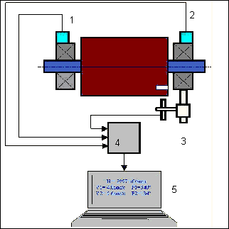
4.1. "Balanset-1A" شامل (شکل ۴.۱) واحد رابط USB است (1)، دو شتابسنج (2) and (3)، نشانگر مرجع فاز (4) و کامپیوتر قابل حمل (همراه دستگاه ارائه نمیشود) (5).
بسته ارسالی شامل پایه مغناطیسی نیز میشود (6) برای نصب نشانگر مرجع فاز و ترازوهای دیجیتال استفاده میشود 7.
X1 and X2 connectors intended for connection of the vibration sensors respectively to 1 and 2 measuring channels, and the X3 connector used for connection of the phase reference marker.
The USB cable provides power supply and connection of the USB interface unit to the computer.

شکل 4.1 مجموعه تحویل "Balanset-1A""
ارتعاشات مکانیکی باعث ایجاد یک سیگنال الکتریکی متناسب با شتاب ارتعاش در خروجی سنسور ارتعاش میشوند. سیگنالهای دیجیتالی شده از ماژول ADC از طریق USB به کامپیوتر قابل حمل منتقل میشوند. (5). نشانگر مرجع فاز، سیگنال پالس مورد استفاده برای محاسبه فرکانس چرخش و زاویه فاز ارتعاش را تولید میکند. نرمافزار مبتنی بر ویندوز، راهحلهایی برای بالانس تک صفحهای و دو صفحهای، تجزیه و تحلیل طیف، نمودارها، گزارشها و ذخیرهسازی ضرایب تأثیر ارائه میدهد.
5. SAFETY PRECAUTIONS
⚡ توجه - ایمنی برق
5.1. When operating on 220V electrical safety regulations must be observed. It is not allowed to repair the device when connected to 220 V.
5.2. اگر از دستگاه در محیطی با برق AC با کیفیت پایین یا در صورت وجود تداخل شبکه استفاده میکنید، توصیه میشود از منبع تغذیه مستقل از باتری کامپیوتر استفاده کنید.
⚠️ الزامات ایمنی تکمیلی برای تجهیزات دوار
- !قفل شدن دستگاه: قبل از نصب سنسورها، همیشه رویههای قفل/برچسبگذاری مناسب را اجرا کنید.
- !تجهیزات حفاظت فردی: از عینک ایمنی و محافظ شنوایی استفاده کنید و از پوشیدن لباسهای گشاد در نزدیکی ماشینآلات دوار خودداری کنید.
- !نصب ایمن: مطمئن شوید که همه سنسورها و کابلها محکم بسته شدهاند و قطعات چرخان به آنها گیر نمیکنند.
- !رویههای اورژانسی: محل توقفهای اضطراری و رویههای خاموش کردن را بدانید
- !آموزش: فقط پرسنل آموزش دیده باید تجهیزات تعادل را روی ماشین آلات دوار کار کنند
۶. تنظیمات نرمافزار و سختافزار
6.1. USB drivers and balancing software installation
Before working install drivers and balancing software.
فهرست پوشهها و فایلها
Installation disk (flash drive) contains the following files and folders:
- Bs1Av###Setup – پوشه حاوی نرمافزار متعادلسازی "Balanset-1A" (شماره نسخه ۱TP5T##)
- آرددرو – درایورهای USB
- راهنمای EBalancer.pdf – این دفترچه راهنما
- Bal1Av###Setup.exe – فایل نصب. این فایل شامل تمام فایلها و پوشههای بایگانی شده ذکر شده در بالا است. ### – نسخه نرمافزار "Balanset-1A".
- Ebalance.cfg - مقدار حساسیت
- بال.ینی - برخی از دادههای اولیهسازی
روش نصب نرمافزار
For installing drivers and specialized software run file Bal1Av###Setup.exe and follow setup instructions by pressing buttons «Next», «ОК» etc.
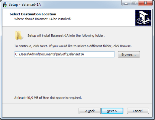
Choose setup folder. Usually the given folder should not be changed.
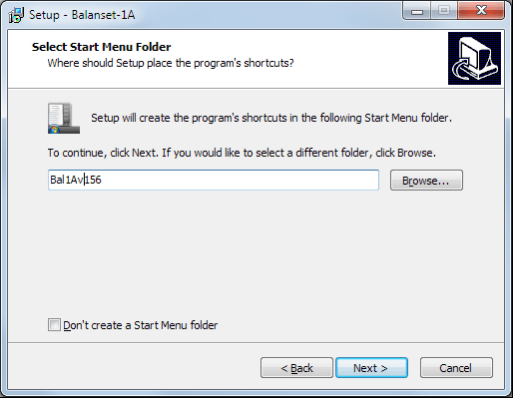
Then the program requires specifying Program group and desktop folders. Press button Next.
نصب نهایی
- ✓Install sensors on the inspected or balanced mechanism (Detailed information about how to install the sensors is given in Annex 1)
- ✓Connect vibration sensors 2 and 3 to the inputs X1 and X2, and phase angle sensor to the input X3 of USB interface unit.
- ✓Connect USB interface unit to the USB-port of the computer.
- ✓هنگام استفاده از منبع تغذیه AC، کامپیوتر را به برق شهری وصل کنید. منبع تغذیه را به ۲۲۰ ولت، ۵۰ هرتز وصل کنید.
- ✓روی میانبر "Balanset-1A" روی دسکتاپ کلیک کنید.
۷. نرمافزار متعادلسازی
۷.۱. عمومی
Initial window
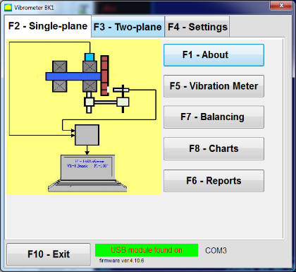
هنگام اجرای برنامه "Balanset-1A"، پنجره اولیه، که در شکل 7.1 نشان داده شده است، ظاهر میشود.

شکل 7.1. پنجره اولیه "Balanset-1A""
در پنجره اولیه 9 دکمه وجود دارد که نام عملکردهایی که با کلیک روی آنها اجرا میشوند، روی آنها نوشته شده است.
F1-«About»
شکل 7.2. پنجره F1-«درباره»
F2-«Single plane», F3-«Two plane»
فشار دادن ""F2- تک صفحهای""(یا F2 کلید تابع روی صفحه کلید کامپیوتر) ارتعاش اندازهگیری را روی کانال انتخاب میکند X1.
After clicking this button, the computer display diagram shown in Fig. 7.1 illustrating a process of measuring the vibration only on the first measuring channel (or the balancing process in a single plane).
با فشار دادن ""F3-دو هواپیما""(یا F3 function key on the computer keyboard) selects the mode of vibration measurements on two channels X1 and X2 simultaneously. (Fig. 7.3.)
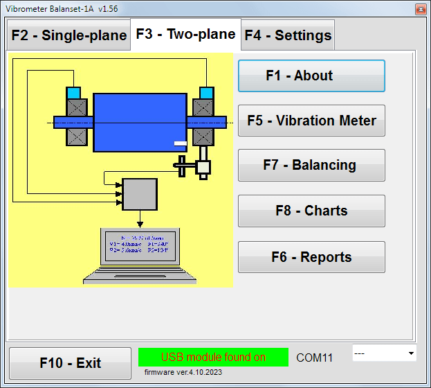
شکل ۷.۳. پنجره اولیه "Balanset-1A". بالانس دو صفحهای.
F4 - «تنظیمات»
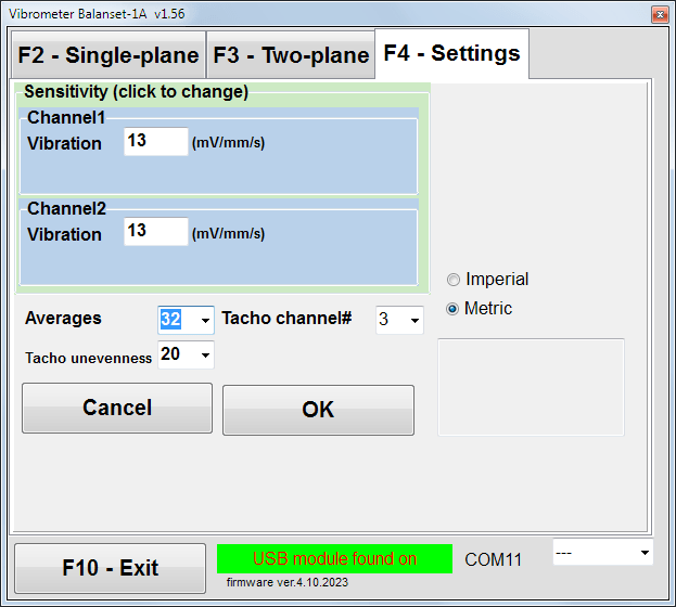
شکل 7.4. پنجره "تنظیمات"
In this window you can change some Balanset-1A settings.
- Sensitivity. The nominal value is 13 mV / mm/s.
Changing the sensitivity coefficients of sensors is required only when replacing sensors!
Attention!
وقتی ضریب حساسیت را وارد میکنید، قسمت کسری آن با نقطه اعشار (علامت ",") از قسمت صحیح جدا میشود.
- Averaging - تعداد میانگینگیری (تعداد چرخشهای روتور که در طول آنها دادهها با دقت بیشتری میانگینگیری میشوند)
- Tacho channel# - کانال# تاچو متصل است. به طور پیشفرض - کانال سوم.
- Unevenness - تفاوت مدت زمان بین پالسهای تاکو مجاور، که در بالا هشدار میدهد ""Failure of the tachometer"
- Imperial/Metric - سیستم واحدها را انتخاب کنید.
Com port number is assigned automatically.
F5 - «لرزش سنج»
Pressing this button (or a function key of F5 روی صفحه کلید کامپیوتر) حالت اندازهگیری ارتعاش را در یک یا دو کانال اندازهگیری ارتعاشسنج مجازی بسته به وضعیت دکمهها فعال میکند."F2-تکصفحهای", ""F3-دو-هواپیما".
F6 - «گزارشها»
Pressing this button (or F6 function key on the computer keyboard) switches on the balancing Archive, from which you can print the report with the results of balancing for a specific mechanism (rotor).
F7 – «Balancing»
با فشردن این دکمه (یا کلید تابعی F7 روی صفحه کلید) حالت تعادل در یک یا دو صفحه اصلاح فعال میشود، بسته به اینکه کدام حالت اندازهگیری با فشردن دکمههای "" انتخاب شده باشد."F2-تکصفحهای", ""F3-دو-هواپیما".
F8 – «Charts»
Pressing this button (or F8 کلید تابع (روی صفحه کلید کامپیوتر) لرزش سنج گرافیکی را فعال میکند، که پیادهسازی آن همزمان با مقادیر دیجیتال دامنه و فاز ارتعاش، نمودارهای تابع زمان آن را روی صفحه نمایش میدهد.
F10 - «خروج»
Pressing this button (or F10 کلید تابع روی صفحه کلید کامپیوتر) برنامه "Balanset-1A" را تکمیل میکند.
۷.۲ "لرزش سنج"
قبل از کار در ""Vibration meter"در حالت "، سنسورهای لرزش را روی دستگاه نصب کنید و آنها را به ترتیب به کانکتورهای X1 و X2 واحد رابط USB وصل کنید. سنسور تاکو باید به ورودی X3 واحد رابط USB وصل شود.

Fig. 7.5 USB interface unit
برای کار با تاچو، نوار بازتابنده را روی سطح روتور قرار دهید.

شکل 7.6. نوار بازتابنده.
Recommendations for the installation and configuration of sensors are given in Annex 1.
برای شروع اندازهگیری در حالت لرزشسنج، روی دکمه "" کلیک کنید."F5 – Vibration Meter"در پنجره اولیه برنامه» (شکل ۷.۱ را ببینید).
Vibration Meter window appears (see. Fig.7.7)

Fig. 7.7. Vibration meter mode. Wave and Spectrum.
برای شروع اندازهگیریهای ارتعاش، روی دکمه "" کلیک کنید."F9 - دویدن"" (یا کلید تابع را فشار دهید F9 on the keyboard).
If حالت فعالسازی: خودکار بررسی میشود - نتایج اندازهگیری ارتعاش به صورت دورهای روی صفحه نمایش داده میشود.
در صورت اندازهگیری همزمان ارتعاش در کانالهای اول و دوم، پنجرههای واقع در زیر عبارت ""Plane 1" و "Plane 2" پر خواهد شد.
اندازهگیری ارتعاش در حالت "لرزش" همچنین میتواند با حسگر زاویه فاز جدا شده انجام شود. در پنجره اولیه برنامه، مقدار کل RMS ارتعاش (V1s, V2s) will only be displayed.
تنظیمات بعدی در حالت لرزش سنج وجود دارد
- RMS پایین، هرتز - کمترین فرکانس برای محاسبه RMS ارتعاش کلی
- پهنای باند - پهنای باند فرکانس ارتعاش در نمودار
- Averages - تعداد میانگین برای دقت بیشتر اندازهگیری
برای تکمیل کار در حالت "لرزش سنج" روی دکمه "" کلیک کنید."F10 – Exit"" و به پنجره اولیه برگردید.

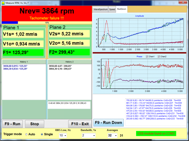
Fig. 7.8. Vibration meter mode. Rotation speed Unevenness, 1x vibration wave form.
Fig. 7.9. Vibration meter mode. Rundown (beta version, no warranty!).
۷.۳ روش متعادلسازی
Balancing is performed for mechanisms in good technical condition and correctly mounted. Otherwise, before the balancing the mechanism must be repaired, installed in proper bearings and fixed. Rotor should be cleaned of contaminants that can hinder from balancing procedure.
Before balancing measure vibration in Vibration meter mode (F5 button) to be sure that mainly vibration is 1x vibration.
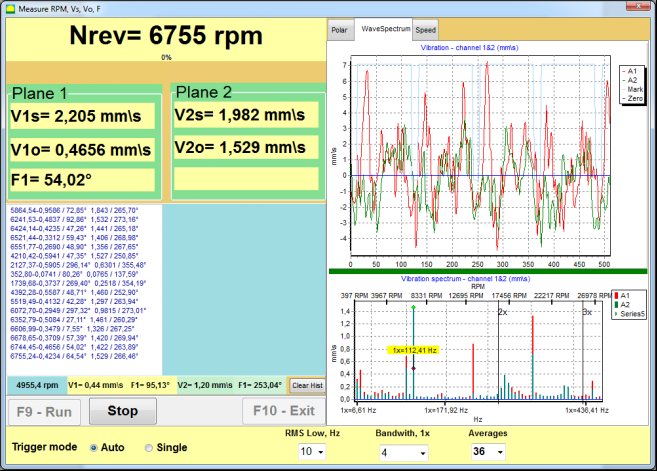
Fig. 7.10. Vibration meter mode. Checking overall (V1s,V2s) and 1x (V1o,V2o) vibration.
اگر مقدار ارتعاش کلی V1s (V2s) تقریباً برابر با بزرگی ارتعاش در فرکانس چرخشی (1x ارتعاش) V1o (V2o) باشد، میتوان فرض کرد که سهم اصلی در مکانیزم ارتعاش از عدم تعادل روتور ناشی میشود. اگر مقدار ارتعاش کلی V1s (V2s) بسیار بیشتر از مؤلفه ارتعاش 1x V1o (V2o) باشد، توصیه میشود وضعیت مکانیزم - وضعیت یاتاقانها، محل نصب آن روی پایه، اطمینان از عدم تماس بین قطعات ثابت و روتور در حین چرخش و غیره - بررسی شود.
همچنین باید به پایداری مقادیر اندازهگیری شده در حالت لرزشسنج توجه کنید - دامنه و فاز لرزش نباید بیش از 10-15% در فرآیند اندازهگیری تغییر کند. در غیر این صورت، میتوان فرض کرد که مکانیزم در ناحیه نزدیک به رزونانس کار میکند. در این حالت، سرعت چرخش روتور را تغییر دهید و اگر این امکان پذیر نیست - شرایط نصب دستگاه روی فونداسیون را تغییر دهید (به عنوان مثال، آن را به طور موقت روی تکیهگاههای فنری نصب کنید).
برای بالانس روتور روش ضریب نفوذ از روش متعادلسازی (روش سه مرحلهای) باید استفاده شود.
Trial runs are done to determine the effect of trial mass on vibration change, mass and place (angle) of installation of correction weights.
First determine the original vibration of a mechanism (first start without weight), and then set the trial weight to the first plane and made the second start. Then, remove the trial weight from the first plane, set in a second plane and made the second start.
The program then calculates and indicates on the screen the weight and location (angle) of installation of correction weights.
When balancing in a single plane (static), the second start is not required.
Trial weight is set to an arbitrary location on the rotor where it is convenient, and then the actual radius is entered in the setup program.
(Position Radius is used only for calculating the unbalance amount in grams * mm)
Important!
- Measurements should be carried out with the constant speed of rotation of the mechanism!
- Correction weights must be installed on the same radius as the trial weights!
جرم وزنه آزمایشی طوری انتخاب میشود که پس از مرحله نصب (> 20-30°) و (20-30%) دامنه ارتعاش به طور قابل توجهی تغییر کند. اگر تغییرات خیلی کوچک باشند، خطا در محاسبات بعدی به میزان زیادی افزایش مییابد. به راحتی وزنه آزمایشی را در همان محل (همان زاویه) علامت فاز قرار دهید.
فرمول محاسبه جرم وزنه آزمایشی
Mt = آقای × پشتیبانی K × ارتعاش K / (Rt × (N/100)²)
کجا:
- کوه - جرم وزنه آزمایشی، گرم
- آقای - جرم روتور، g
- پشتیبانی - ضریب سختی تکیهگاه (1-5)
- کوویبراسیون - ضریب سطح ارتعاش (0.5-2.5)
- رت - شعاع نصب وزنه آزمایشی، سانتیمتر
- ن - سرعت روتور، دور در دقیقه
ضریب سختی تکیهگاه (Ksupport):
- 1.0 - تکیهگاههای بسیار نرم (کمک فنرهای لاستیکی)
- 2.0-3.0 - سختی متوسط (بلبرینگهای استاندارد)
- 4.0-5.0 - تکیهگاههای صلب (پی عظیم)
ضریب سطح ارتعاش (Kvibration):
- 0.5 - لرزش کم (تا 5 میلیمتر بر ثانیه)
- 1.0 - ارتعاش عادی (5-10 میلیمتر بر ثانیه)
- 1.5 - ارتعاش بالا (10-20 میلیمتر بر ثانیه)
- 2.0 - ارتعاش بالا (20-40 میلیمتر بر ثانیه)
- 2.5 - لرزش بسیار زیاد (>40 میلیمتر بر ثانیه)
🔗 از ماشین حساب آنلاین ما استفاده کنید:
محاسبهگر وزن آزمایشی →⚠️ مهم!
After each test run trial mass are removed! Correction weights set at an angle calculated from the place of trial weight installation in the direction of rotation of the rotor!
توضیح محاسبه زاویه:
زاویه نصب وزنه اصلاح عبارت است از همیشه از نقطه نصب وزنه آزمایشی در جهت چرخش روتور شمارش میشود.
- نقطه صفر (0°): محل دقیقی که وزنه آزمایشی را نصب کردهاید، نقطه مرجع شما (0 درجه) خواهد بود.
- جهت: زاویه را در همان جهتی که روتور میچرخد، اندازهگیری کنید.
مثال: اگر روتور در جهت عقربههای ساعت میچرخد، زاویه را در جهت عقربههای ساعت از موقعیت وزنه آزمایشی اندازهگیری کنید. - تفسیر: اگر برنامه زاویه ای از ۱۲۰ درجه, شما باید وزنه اصلاح را نصب کنید ۱۲۰ درجه جلوتر موقعیت وزنه آزمایشی در جهت چرخش.
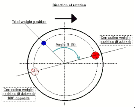
Fig. 7.11. Correction weight mounting.
توصیه میشود!
قبل از انجام بالانس دینامیکی، توصیه میشود مطمئن شوید که عدم تعادل استاتیک خیلی زیاد نباشد. برای روتورهایی با محور افقی، روتور را میتوان به صورت دستی با زاویه ۹۰ درجه از موقعیت فعلی چرخاند. اگر روتور از نظر استاتیکی نامتعادل باشد، به موقعیت تعادل چرخانده میشود. پس از اینکه روتور در موقعیت تعادل قرار گرفت، لازم است وزنه تعادل را در نقطه بالایی تقریباً در قسمت میانی طول روتور نصب کنید. وزنه باید به گونهای انتخاب شود که روتور در هیچ موقعیتی حرکت نکند.
چنین پیش متعادلسازی، میزان ارتعاش را در اولین شروع یک روتور به شدت نامتعادل کاهش میدهد.
نصب و مونتاژ سنسور
Vibration sensor must be installed on the machine in the selected measuring point and connected to the input X1 of the USB interface unit.
دو پیکربندی نصب وجود دارد:
- آهنرباها
- Threaded studs M4
Optical tacho sensor should be connected to the input X3 of the USB interface unit. Furthermore, for use of this sensor a special reflecting mark should be applied on surface of a rotor.
📏 الزامات نصب حسگر نوری
- ✓فاصله تا سطح روتور: ۵۰-۵۰۰ میلیمتر (بسته به مدل حسگر)
- ✓عرض نوار بازتابنده: حداقل ۱ تا ۱.۵ سانتیمتر (بستگی به سرعت و شعاع دارد)
- ✓جهت گیری: عمود بر سطح روتور
- ✓نصب: برای قرارگیری پایدار از پایه یا گیره مغناطیسی استفاده کنید
- ✓از تابش مستقیم نور خورشید خودداری کنید یا نور مصنوعی شدید روی حسگر/نوار
💡 محاسبه عرض نوار: برای عملکرد بهینه، عرض نوار را با استفاده از موارد زیر محاسبه کنید:
طول ≥ (عرض × عرض)/30000 ≥ 1.0-1.5 سانتیمتر
که در آن: L - عرض نوار (سانتیمتر)، N - سرعت روتور (دور در دقیقه)، R - شعاع نوار (سانتیمتر)
Detailed requirements on site selection of the sensors and their attachment to the object when balancing are set out in Annex 1.
۷.۴ بالانس تک صفحهای
شکل 7.12. "متعادل سازی تک صفحه ای"
بایگانی متعادلسازی
برای شروع کار روی برنامه در ""Single-Plane balancing"حالت، روی " کلیک کنید"F2-Single-plane"دکمه " (یا کلید F2 را روی صفحه کلید کامپیوتر فشار دهید).
سپس روی "کلیک کنید""F7 – Balancing"دکمهی «»، که پس از آن Single Plane balancing archive window will appear, in which the balancing data will be saved (see Fig. 7.13).

Fig. 7.13 The window for selecting the balancing archive in single plane.
In this window, you need to enter data on the name of the rotor (Rotor name), place of rotor installation (Place), tolerances for vibration and residual imbalance (Tolerance), date of measurement. This data is stored in a database. Also, a folder Arc### is created in, where ### is the number of the archive in which the charts, a report file, etc. will be saved. After the balancing is completed, a report file will be generated that can be edited and printed in the built-in editor.
پس از وارد کردن اطلاعات لازم، باید روی "" کلیک کنید."F10-OK"دکمهی "، که پس از آن ""Single-Plane balancing"پنجره باز خواهد شد (شکل 7.13 را ببینید)
Balancing settings (1-plane)

Fig. 7.14. Single plane. Balancing settings
در سمت چپ این پنجره، دادههای اندازهگیری ارتعاش و دکمههای کنترل اندازهگیری نمایش داده میشوند."Run # 0", "Run # 1", "RunTrim".
در سمت راست این پنجره سه تب وجود دارد:
- Balancing settings
- Charts
- Result
""Balancing settings"از تب " برای وارد کردن تنظیمات تعادل استفاده میشود:
- "ضریب نفوذ" -
- "New Rotor""- انتخاب بالانس روتور جدید، که برای آن هیچ ضریب بالانس ذخیره شدهای وجود ندارد و دو بار برای تعیین جرم و زاویه نصب وزنه اصلاح لازم است.
- "Saved coeff.""- انتخاب متعادلسازی مجدد روتور، که برای آن ضرایب متعادلسازی ذخیره شده وجود دارد و تنها یک بار اجرا برای تعیین وزن و زاویه نصب وزنه اصلاحی مورد نیاز است.
- ""وزن آزمایشی"" -
- "Percent"" - وزن اصلاحی به عنوان درصدی از وزن آزمایشی محاسبه میشود.
- "Gram"" - جرم معلوم وزنه آزمایشی وارد شده و جرم وزنه اصلاحی محاسبه میشود. grams or in oz for Imperial system.
⚠️ توجه! در صورت لزوم استفاده از ""Saved coeff."برای کار بیشتر در طول بالانس اولیه، جرم وزنه آزمایشی باید بر حسب گرم یا اونس وارد شود، نه بر حسب %.» ترازوها در بستهبندی تحویلی موجود هستند.
- "روش اتصال وزن"
- "Free position""- وزنهها را میتوان در موقعیتهای زاویهای دلخواه روی محیط روتور نصب کرد.
- "Fixed position"" - وزنه را میتوان در موقعیتهای زاویهای ثابت روی روتور، مثلاً روی پرهها یا سوراخها (مثلاً ۱۲ سوراخ - ۳۰ درجه) و غیره نصب کرد. تعداد موقعیتهای ثابت باید در فیلد مناسب وارد شود. پس از متعادلسازی، برنامه به طور خودکار وزنه را به دو قسمت تقسیم میکند و تعداد موقعیتهایی را که برای تعیین جرمهای به دست آمده لازم است، نشان میدهد.
- "Circular groove""- برای بالانس کردن چرخ سنگ زنی استفاده میشود. در این مورد از ۳ وزنه تعادل برای از بین بردن عدم بالانسی استفاده میشود.
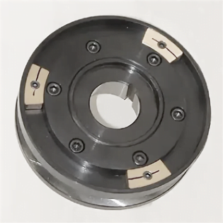
Fig. 7.17 Grinding wheel balancing with 3 counterweights
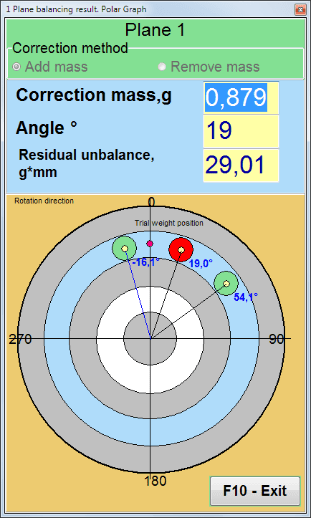
Fig. 7.18 Grinding wheel balancing. Polar graph.

Fig. 7.15. Result tab. Fixed position of correction weight mounting.
Z1 و Z2 – موقعیت وزنههای اصلاحی نصب شده، که از موقعیت Z1 بر اساس جهت چرخش محاسبه میشوند. Z1 موقعیتی است که وزنه آزمایشی در آن نصب شده است.
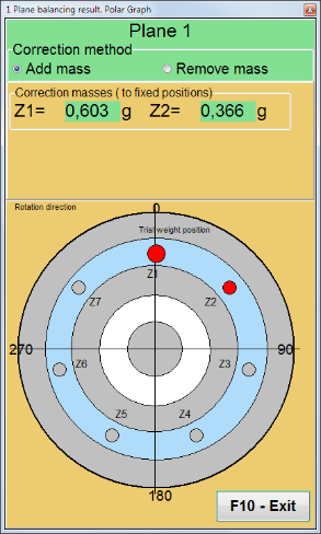
Fig. 7.16 Fixed positions. Polar diagram.
- "Mass mount radius, mm""- "صفحه ۱" - شعاع وزنه آزمایشی در صفحه ۱. برای تعیین انطباق با تلرانس عدم تعادل باقیمانده پس از بالانس، لازم است مقدار عدم تعادل اولیه و باقیمانده محاسبه شود.
- "Leave trial weight in Plane1."معمولاً وزنه آزمایشی در طول فرآیند بالانسینگ برداشته میشود. اما در برخی موارد برداشتن آن غیرممکن است، پس باید در این قسمت یک علامت بزنید تا جرم وزنه آزمایشی در محاسبات لحاظ شود.
- "Manual data input"" - برای وارد کردن دستی مقدار ارتعاش و فاز در فیلدهای مربوطه در سمت چپ پنجره و محاسبه جرم و زاویه نصب وزنه اصلاح هنگام تغییر به " استفاده میشود."Results"برگه "
- دکمه ""Restore session data"". در حین متعادلسازی، دادههای اندازهگیری شده در فایل session1.ini ذخیره میشوند. اگر فرآیند اندازهگیری به دلیل انجماد کامپیوتر یا به دلایل دیگر قطع شده باشد، با کلیک بر روی این دکمه میتوانید دادههای اندازهگیری را بازیابی کرده و از لحظه وقفه، متعادلسازی را ادامه دهید.
- Mandrel eccentricity elimination (Index balancing) Balancing with additional start to eliminate the influence of the eccentricity of the mandrel (balancing arbor). Mount the rotor alternately at 0° and 180° relative to the. Measure the unbalances in both positions.
- Balancing tolerance Entering or calculating residual imbalance tolerances in g x mm (G-classes)
- Use Polar Graph Use polar graph to display balancing results
1-plane Balancing. New rotor
همانطور که در بالا ذکر شد، ""New Rotor"بالانس کردن نیاز به دو بار تست و حداقل یک بار تنظیم دستگاه بالانس دارد.».
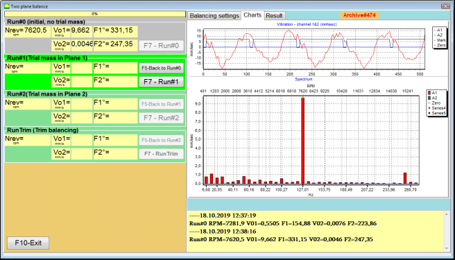
Run#0 (Initial run)
پس از نصب سنسورها روی روتور متعادل کننده و وارد کردن پارامترهای تنظیمات، لازم است چرخش روتور را روشن کنید و وقتی به سرعت کار رسید، دکمه "" را فشار دهید."Run#0"دکمهی " برای شروع اندازهگیریها. ""Charts"تب "" در پنل سمت راست باز میشود، جایی که شکل موج و طیف ارتعاش نشان داده میشود. در قسمت پایین تب، یک فایل تاریخچه نگهداری میشود که در آن نتایج همه موارد با مرجع زمانی ذخیره میشوند. این فایل در دیسک در پوشه بایگانی با نام memo.txt ذخیره میشود.
Attention!
Before starting the measurement, it is necessary to turn on the rotation of the rotor of the balancing machine (Run#0) and make sure that the rotor speed is stable.
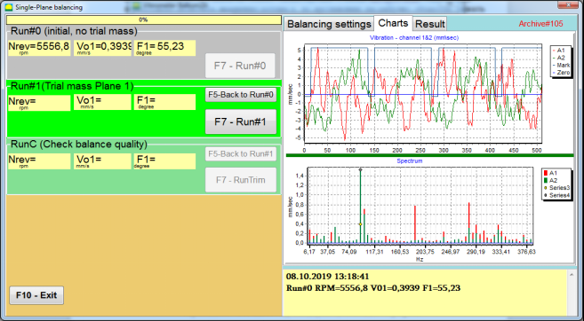
Fig. 7.19. Balancing in one plane. Initial run (Run#0). Charts Tab
After measurement process finished, in the Run#0 در بخش سمت چپ، نتایج اندازهگیری ظاهر میشود - سرعت روتور (RPM)، RMS (Vo1) و فاز (F1) ارتعاش 1x.
""F5-Back to Run#0"دکمه " (یا کلید تابعی F5) برای بازگشت به بخش Run#0 و در صورت لزوم، برای تکرار اندازهگیری پارامترهای ارتعاش استفاده میشود.
Run#1 (Trial mass Plane 1)
قبل از شروع اندازهگیری پارامترهای ارتعاش در بخش ""Run#1 (Trial mass Plane 1), ، یک وزنه آزمایشی باید طبق ""Trial weight mass"میدان.
The goal of installing a trial weight is to evaluate how the vibration of the rotor changes when a known weight is installed at a known place (angle). Trial weight must changes the vibration amplitude by either 30% lower or higher of initial amplitude or change phase by 30 degrees or more of initial phase.
در صورت لزوم استفاده از ""Saved coeff."برای انجام کار بیشتر در حالت تعادل، محل (زاویه) نصب وزنه آزمایشی باید با محل (زاویه) علامت بازتابنده یکسان باشد.
چرخش روتور دستگاه متعادل کننده را دوباره روشن کنید و مطمئن شوید که فرکانس چرخش آن پایدار است. سپس روی ""F7-Run#1"دکمه " (یا کلید F7 را روی صفحه کلید کامپیوتر فشار دهید).
پس از اندازهگیری در پنجرههای مربوطه از ""Run#1 (Trial mass Plane 1)"بخش "، نتایج اندازهگیری سرعت روتور (RPM)، و همچنین مقدار مؤلفه RMS (V₂1) و فاز (F₂1) ارتعاش 1x ظاهر میشود.
در همان زمان، ""Result"تب " در سمت راست پنجره باز میشود.
This tab displays the results of calculating the mass and angle of corrective weight, which must be installed on the rotor to compensate imbalance.
علاوه بر این، در صورت استفاده از سیستم مختصات قطبی، صفحه نمایش مقدار جرم (M1) و زاویه نصب (f1) وزنه اصلاح را نشان میدهد.
در مورد "Fixed positions"شماره موقعیتها (Zi، Zj) و جرم تقسیمشده وزنه آزمایشی نشان داده خواهد شد.
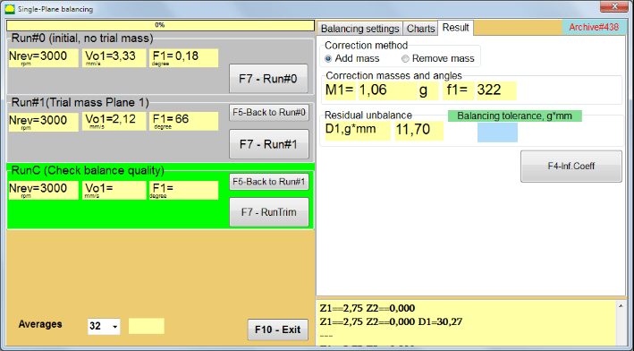
Fig. 7.20. Balancing in one plane. Run#1 and balancing result.
If Polar graph is checked polar diagram will be shown.
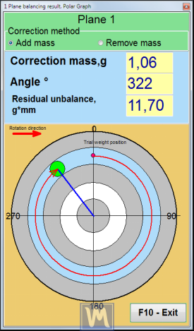
Fig. 7.21. The result of balancing. Polar graph.
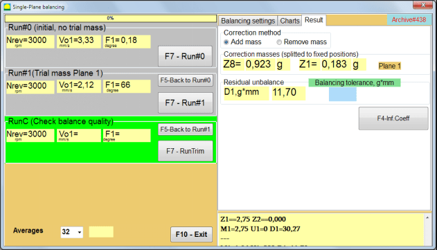
Fig. 7.22. The result of balancing. Weight splitted (fixed positions)
همچنین اگر ""Polar graph"" علامت زده شد، نمودار قطبی نشان داده خواهد شد.
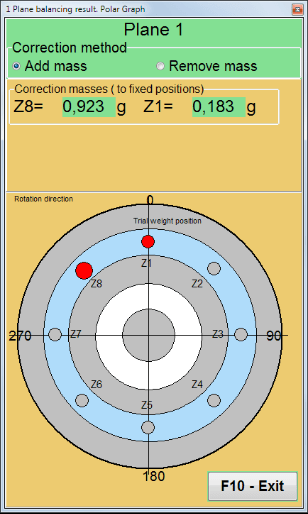
Fig. 7.23. Weight splitted on fixed positions. Polar graph
⚠️ توجه!
- پس از تکمیل فرآیند اندازهگیری در اجرای دوم (""Run#1 (Trial mass Plane 1)"") دستگاه بالانس، لازم است چرخش را متوقف کرده و وزنه آزمایشی نصب شده را بردارید. سپس وزنه اصلاحی را بر اساس دادههای جدول نتایج روی روتور نصب (یا بردارید).
اگر وزنه آزمایشی برداشته نشده بود، باید به ""Balancing settings""تب بزنید و کادر انتخاب را در ""Leave trial weight in Plane1"". سپس به " برگردید"Result"تب ". وزن و زاویه نصب وزنه اصلاح به طور خودکار دوباره محاسبه میشوند.
- موقعیت زاویهای وزنه اصلاحی از محل نصب وزنه آزمایشی انجام میشود. جهت مرجع زاویه با جهت چرخش روتور همزمان است.
- در مورد "Fixed position""- 1st position (Z1), coincides with the place of installation of the trial weight. The counting direction of the position number is in the direction of rotation of the rotor.
- به طور پیشفرض، وزن اصلاحی به روتور اضافه میشود. این با برچسب تنظیم شده در "" نشان داده شده است."Add"اگر وزنه را برمیدارید (مثلاً با سوراخ کردن)، باید علامتی در قسمت ""Delete"" فیلد، که پس از آن موقعیت زاویهای وزنه اصلاح به طور خودکار ۱۸۰ درجه تغییر میکند.
پس از نصب وزنه اصلاح بر روی روتور متعادل کننده در پنجره عملیاتی، لازم است RunC (تریم) انجام شود و اثربخشی متعادل سازی انجام شده ارزیابی شود.
RunC (Check balance quality)
⚠️ توجه! Before starting the measurement on the RunC, it is necessary to turn on the rotation of the rotor of the machine and make sure that it has entered the operating mode (stable rotation frequency).
برای انجام اندازهگیری ارتعاش در ""RunC (Check balance quality)"بخش "، روی" کلیک کنید"F7 – RunTrim"دکمه " (یا کلید F7 را روی صفحه کلید فشار دهید).
پس از اتمام موفقیتآمیز فرآیند اندازهگیری، در ""RunC (Check balance quality)"در بخش " در پنل سمت چپ، نتایج اندازهگیری سرعت روتور (RPM) و همچنین مقدار مؤلفه RMS (Vo1) و فاز (F1) ارتعاش 1x نمایش داده میشود.
در ""Result"تب "، نتایج محاسبه جرم و زاویه نصب وزنه اصلاحی اضافی نمایش داده میشود.
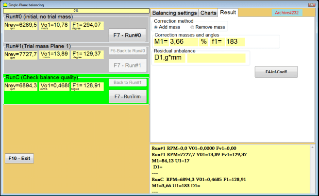
Fig. 7.24. Balancing in one plane. Performing a RunTrim. Result Tab
This weight can be added to the correction weight that is already mounted on the rotor to compensate for the residual imbalance. In addition, the residual rotor unbalance achieved after balancing is displayed in the lower part of this window.
In the case when the amount of residual vibration and / or residual unbalance of the balanced rotor meets the tolerance requirements established in the technical documentation, the balancing process can be completed.
Otherwise, the balancing process may continue. This allows the method of successive approximations to correct possible errors that may occur during the installation (removal) of the corrective weight on a balanced rotor.
هنگام ادامه فرآیند تعادل روی روتور تعادل، لازم است جرم اصلاحی اضافی نصب (حذف) شود، پارامترهای آن در بخش ""Correction masses and angles".
Influence coefficients (1-plane)
""F4-Inf.Coeff"دکمهی "در""Result"از تب " برای مشاهده و ذخیره ضرایب بالانس روتور (ضرایب تأثیر) محاسبه شده از نتایج کالیبراسیون در حافظه کامپیوتر استفاده میشود.
وقتی فشار داده میشود، ""Influence coefficients (single plane)"پنجرهای روی صفحه نمایش کامپیوتر ظاهر میشود که در آن ضرایب بالانس محاسبهشده از نتایج کالیبراسیون (آزمایش) نمایش داده میشوند. اگر قرار باشد در طول بالانس بعدی این دستگاه از ... استفاده شود."Saved coeff."حالت، این ضرایب باید در حافظه کامپیوتر ذخیره شوند.
برای انجام این کار، روی "" کلیک کنید"F9 - ذخیره""را فشار دهید و به صفحه دوم بروید""ضریب نفوذ. بایگانی. صفحه تکی."

Fig. 7.25. Balancing coefficients in the 1st plane
سپس باید نام این دستگاه را در قسمت "" وارد کنید."Rotor""ستون و کلیک""F2-Save"دکمه " را برای ذخیره دادههای مشخص شده در رایانه فشار دهید.
سپس میتوانید با فشردن دکمه " به پنجره قبلی بازگردید."F10-Exit"دکمه " (یا کلید تابعی F10 روی صفحه کلید کامپیوتر).
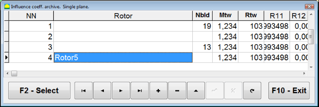
شکل ۷.۲۶. "ضریب تأثیر. بایگانی. صفحه واحد."
Balancing report
پس از متعادلسازی تمام دادهها ذخیره و گزارش متعادلسازی ایجاد شد. میتوانید گزارش را در ویرایشگر داخلی مشاهده و ویرایش کنید. در پنجره ""متعادل کردن بایگانی در یک صفحه"" (شکل 7.9) دکمه را فشار دهید ""F9 -Report"برای دسترسی به ویرایشگر گزارش تعادل.
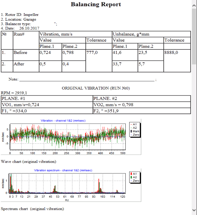
شکل ۷.۲۷. گزارش ترازبندی.
رویه متعادلسازی ضرایب ذخیرهشده با ضرایب تأثیر ذخیرهشده در یک صفحه
راهاندازی سیستم اندازهگیری (ورودی دادههای اولیه)
Saved coeff. balancing can be performed on a machine for which balancing coefficients have already been determined and entered into the computer memory.
⚠️ توجه! When balancing with saved coefficients, the vibration sensor and the phase angle sensor must be installed in the same way as during the initial balancing.
Input of the initial data for Saved coeff. balancing (مانند مورد اولیه(""New rotor"") ایجاد تعادل) در " آغاز میشود"Single plane balancing. Balancing settings.".
در این حالت، در ""Influence coefficients"بخش "، را انتخاب کنید""Saved coeff"مورد. در این مورد، صفحه دوم"Influence coeff. archive. Single plane."، که بایگانی از ضرایب متعادل ذخیره شده را ذخیره میکند.
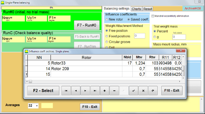
Fig. 7.28. Balancing with saved influence coefficients in 1 plane
با استفاده از دکمههای کنترل "►" یا "◄" در جدول این بایگانی، میتوانید رکورد مورد نظر را با ضرایب متعادلکننده دستگاه مورد علاقه ما انتخاب کنید. سپس، برای استفاده از این دادهها در اندازهگیریهای فعلی، دکمه ""F2 – Select"دکمهی «.
پس از آن، محتویات تمام پنجرههای دیگرِ ""Single plane balancing. Balancing settings."" به طور خودکار پر می شوند.
After completing the input of the initial data, you can begin to measure.
اندازهگیریها در حین بالانس با ضرایب تأثیر ذخیرهشده
Balancing with saved influence coefficients requires only one initial run and at least one test run of the balancing machine.
⚠️ توجه! Before starting the measurement, it is necessary to turn on the rotation of the rotor and make sure that rotating frequency is stable.
برای انجام اندازهگیری پارامترهای ارتعاش در ""Run#0 (Initial, no trial mass)"بخش، فشار دهید"F7 – Run#0"(یا کلید F7 را روی صفحه کلید کامپیوتر فشار دهید).
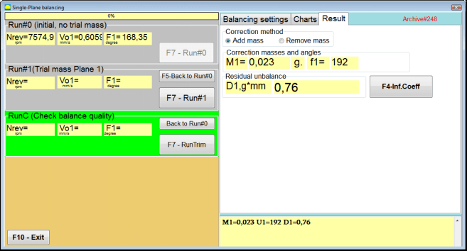
Fig. 7.29. Balancing with saved influence coefficients in one plane. Results after one run.
در فیلدهای مربوطه ""Run#0"در بخش "، نتایج اندازهگیری سرعت روتور (RPM)، مقدار مؤلفه RMS (V₂1) و فاز (F₂1) ارتعاش 1x ظاهر میشود.
در همان زمان، ""Result"تب " نتایج محاسبه جرم و زاویه وزنه اصلاحی را نمایش میدهد که باید برای جبران عدم تعادل روی روتور نصب شود.
علاوه بر این، در صورت استفاده از سیستم مختصات قطبی، صفحه نمایش مقادیر جرم و زوایای نصب وزنههای اصلاح را نشان میدهد.
In the case of splitting of the corrective weight on the fixed positions, the numbers of the positions of the balancing rotor and the mass of weight that need to be installed on them are displayed.
Further, the balancing process is carried out in accordance with the recommendations set out in section 7.4.2. for primary balancing.
Mandrel eccentricity elimination (Index balancing)
If during balancing the rotor is installed in a cylindrical mandrel, then the eccentricity of the mandrel may introduce an additional error. To eliminate this error, the rotor should be deployed in the mandrel 180 degrees and carry out an additional start. This is called index balancing.
To carry out index balancing, a special option is provided in the Balanset-1A program. When checked Mandrel eccentricity elimination an additional RunEcc section appears in the balancing window.

Fig. 7.30. The working window for Index balancing.
After running Run # 1 (Trial mass Plane 1), a window will appear
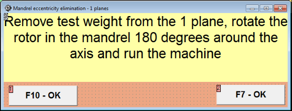
Fig. 7.31 Index balancing attention window.
پس از نصب روتور با چرخش ۱۸۰ درجه، باید Run Ecc تکمیل شود. برنامه به طور خودکار عدم تعادل واقعی روتور را بدون تأثیر بر خروج از مرکز مندرل محاسبه میکند.
۷.۵ بالانس دو صفحهای
Before starting work in the Two plane balancing mode, it is necessary to install vibration sensors on the machine body at the selected measurement points and connect them to the inputs X1 and X2 of the measuring unit, respectively.
An optical phase angle sensor must be connected to input X3 of the measuring unit. In addition, to use this sensor, a reflective tape must be glued onto the accessible rotor surface of the balancing machine.
Detailed requirements for choosing the installation location of sensors and their mounting at the facility during balancing are set out in Appendix 1.
کار روی این برنامه در ""Two plane balancing"حالت " از پنجره اصلی برنامهها شروع میشود.
روی " کلیک کنید"F3-Two plane"دکمه " (یا کلید F3 را روی صفحه کلید کامپیوتر فشار دهید).
علاوه بر این، روی دکمه "F7 - متعادل سازی" کلیک کنید، پس از آن یک پنجره کاری روی صفحه نمایش کامپیوتر ظاهر می شود (شکل 7.13 را ببینید)، انتخاب بایگانی برای ذخیره داده ها هنگام تعادل در دو صفحه.
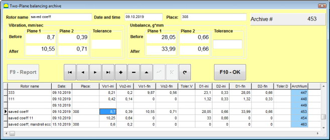
Fig. 7.32 Two plane balancing archive window.
در این پنجره باید دادههای روتور متعادل را وارد کنید. پس از فشار دادن ""F10-OK"دکمهی "، یک پنجرهی متعادلسازی ظاهر خواهد شد.
Balancing settings (2-plane)
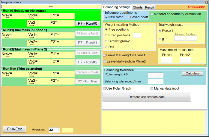
Fig. 7.33. Balancing in two planes window.
در سمت راست پنجره "" قرار دارد."Balancing settings"تب " برای وارد کردن تنظیمات قبل از ایجاد تعادل.
- Influence coefficients - بالانس کردن یک روتور جدید یا بالانس کردن با استفاده از ضرایب تأثیر ذخیره شده (ضرایب بالانس)
- Mandrel eccentricity elimination - متعادلسازی با شروع اضافی برای از بین بردن تأثیر خروج از مرکز مندرل
- Weight Attachment Method - نصب وزنههای اصلاحی در مکانی دلخواه روی محیط روتور یا در یک موقعیت ثابت. محاسبات مربوط به سوراخکاری هنگام برداشتن جرم.
- "Free position""- وزنهها را میتوان در موقعیتهای زاویهای دلخواه روی محیط روتور نصب کرد.
- "Fixed position"" - وزنه را میتوان در موقعیتهای زاویهای ثابت روی روتور، مثلاً روی پرهها یا سوراخها (مثلاً ۱۲ سوراخ - ۳۰ درجه) و غیره نصب کرد. تعداد موقعیتهای ثابت باید در فیلد مناسب وارد شود. پس از متعادلسازی، برنامه به طور خودکار وزنه را به دو قسمت تقسیم میکند و تعداد موقعیتهایی را که برای تعیین جرمهای به دست آمده لازم است، نشان میدهد.
- Trial weight mass - وزن آزمایشی
- Leave trial weight in Plane1 / Plane2 - هنگام بالانس کردن، وزنه آزمایشی را بردارید یا بگذارید.
- Mass mount radius, mm - شعاع نصب وزنههای آزمایشی و اصلاحی
- Balancing tolerance - وارد کردن یا محاسبه تلرانسهای عدم تعادل باقیمانده بر حسب گرم-میلیمتر
- Use Polar Graph - استفاده از نمودار قطبی برای نمایش نتایج متعادلسازی
- Manual data input - ورود دستی دادهها برای محاسبه وزنههای تعادل
- Restore last session data - بازیابی دادههای اندازهگیری آخرین جلسه در صورت عدم موفقیت در ادامه متعادلسازی.
2 planes balancing. New rotor
راهاندازی سیستم اندازهگیری (ورودی دادههای اولیه)
Input of the initial data for the New rotor balancing در ""بالانس دو صفحهای. تنظیمات".
در این حالت، در ""Influence coefficients"بخش "، را انتخاب کنید""New rotor"مورد.
علاوه بر این، در بخش ""Trial weight mass""، شما باید واحد اندازهگیری جرم وزنه آزمایشی را انتخاب کنید -""Gram"یا"Percent".
هنگام انتخاب واحد اندازهگیری ""Percent"، تمام محاسبات بعدی جرم وزنه اصلاحی به صورت درصدی نسبت به جرم وزنه آزمایشی انجام خواهد شد.».
هنگام انتخاب ""Gram"" واحد اندازهگیری، تمام محاسبات بیشتر جرم وزن اصلاحی بر حسب گرم انجام خواهد شد. سپس در پنجرههای واقع در سمت راست کتیبه وارد کنید ""Gram"جرم وزنههای آزمایشی که روی روتور نصب خواهند شد.».
⚠️ توجه! در صورت لزوم استفاده از ""Saved coeff."حالتی برای کار بیشتر در طول بالانس اولیه، جرم وزنههای آزمایشی باید وارد شود» grams.
سپس انتخاب کنید ""Weight Attachment Method" - "Circum"یا"Fixed position".
اگر انتخاب کنید ""Fixed position""، شما باید تعداد موقعیتها را وارد کنید.
Calculation of tolerance for residual imbalance (Balancing tolerance)
تلرانس عدم تعادل باقیمانده (تلرانس تعادل) را میتوان مطابق با رویه شرح داده شده در استاندارد ISO 1940 با عنوان ارتعاش محاسبه کرد. الزامات کیفیت تعادل برای روتورها در حالت ثابت (صلب). بخش 1. مشخصات و تأیید تلرانسهای تعادل.

Fig. 7.34. Balancing tolerance calculation window
Initial run (Run#0)
هنگام تعادل در دو صفحه در ""New rotor"در حالت «بالانس»، انجام سه بار کالیبراسیون و حداقل یک بار تست دستگاه بالانس ضروری است.
اندازهگیری ارتعاش در اولین شروع به کار دستگاه در ""Two plane balance""پنجره کاری در""Run#0"بخش.
شکل ۷.۳۵. نتایج اندازهگیری در حالت تعادل در دو صفحه پس از اجرای اولیه.
⚠️ توجه! قبل از شروع اندازهگیری، لازم است چرخش روتور دستگاه متعادلکننده (اولین اجرا) را روشن کنید و مطمئن شوید که با سرعت پایدار وارد حالت عملیاتی شده است.
To measure vibration parameters in the Run#0 بخش، روی ""F7 – Run#0"دکمه " (یا کلید F7 را روی صفحه کلید کامپیوتر فشار دهید)
نتایج اندازهگیری سرعت روتور (RPM)، مقدار RMS (V₂1، V₂2) و فازهای (F₂، F₂2) ارتعاش 1x در پنجرههای مربوطه ظاهر میشوند. Run#0 section.
Run#1.Trial mass in Plane1
قبل از شروع اندازهگیری پارامترهای ارتعاش در ""Run#1.Trial mass in Plane1"بخش "، شما باید چرخش روتور دستگاه تعادل را متوقف کنید و یک وزنه آزمایشی روی آن نصب کنید، جرم انتخاب شده در»Trial weight mass"بخش.
⚠️ توجه!
- مسئله انتخاب جرم وزنههای آزمایشی و محل نصب آنها روی روتور دستگاه متعادلکننده، به تفصیل در پیوست ۱ مورد بحث قرار گرفته است.
- در صورت لزوم استفاده از Saved coeff. Mode in future work, the place for installing the trial weight must necessarily coincide with the place for installing the mark used to read the phase angle.
After this, it is necessary to turn on the rotation of the rotor of the balancing machine again and make sure that it has entered the operating mode.
برای اندازهگیری پارامترهای ارتعاش در ""Run # 1.Trial mass in Plane1"بخش "، روی" کلیک کنید"F7 – Run#1"دکمه " (یا کلید F7 را روی صفحه کلید کامپیوتر فشار دهید).
پس از اتمام موفقیتآمیز فرآیند اندازهگیری، به برگه نتایج اندازهگیری بازگردانده میشوید.
در این حالت، در پنجرههای مربوطه از ""Run#1. Trial mass in Plane1"بخش "، نتایج اندازهگیری سرعت روتور (RPM)، و همچنین مقدار اجزای RMS (Vo1، Vo2) و فازها (F1، F2) از ارتعاش 1x.
""اجرای # 2. آزمایش جرم در Plane2""
قبل از شروع اندازهگیری پارامترهای ارتعاش در بخش ""Run # 2.Trial mass in Plane2""، شما باید مراحل زیر را انجام دهید:
- چرخش روتور دستگاه متعادل کننده را متوقف کنید.
- وزنه آزمایشی نصب شده در صفحه ۱ را بردارید.
- یک وزنه آزمایشی در صفحه ۲ نصب کنید، جرم انتخاب شده در بخش ""Trial weight mass".
After this, turn on the rotation of the rotor of the balancing machine and make sure that it has entered the operating speed.
برای شروع اندازهگیری ارتعاش در ""Run # 2.Trial mass in Plane2"بخش "، روی" کلیک کنید"F7 – Run # 2"دکمهی " (یا کلید F7 را روی صفحه کلید کامپیوتر فشار دهید). سپس ""Result"برگه " باز میشود.
In the case of using the Weight Attachment Method" - "Free positions، صفحه نمایش مقادیر جرم (M1، M2) و زوایای نصب (f1، f2) وزنههای اصلاحی را نشان میدهد.
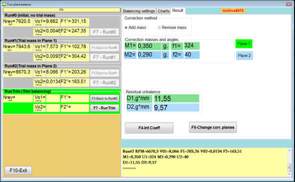
Fig. 7.36. Results of calculation of corrective weights – free position
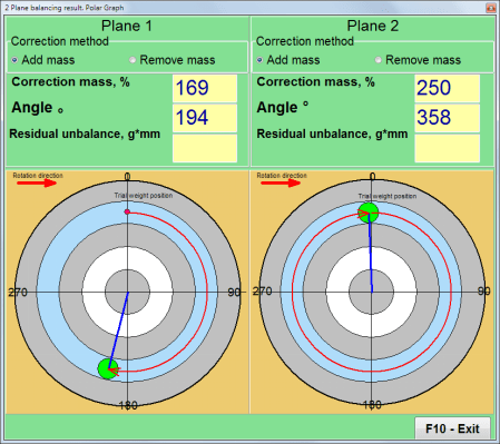
شکل ۷.۳۷. نتایج محاسبه وزنهای اصلاحی - موقعیت آزاد. نمودار قطبی
In the case of using the Weight Attachment Method" – "Fixed positions

شکل ۷.۳۸. نتایج محاسبه وزنهای اصلاحی - موقعیت ثابت.
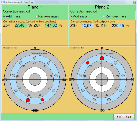
شکل ۷.۳۹. نتایج محاسبه وزنهای اصلاحی - موقعیت ثابت. نمودار قطبی.
در صورت استفاده از روش اتصال وزنه" – ""Circular groove"
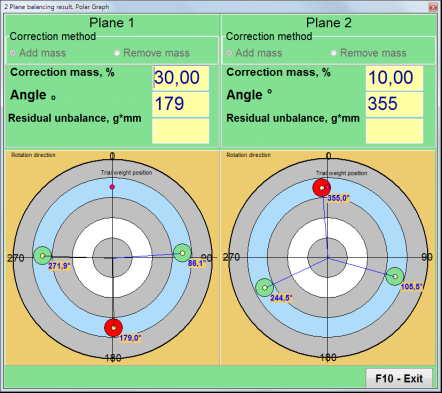
شکل ۷.۴۰. نتایج محاسبه وزنهای اصلاحی – شیار دایرهای.
⚠️ توجه!
- پس از اتمام فرآیند اندازهگیری روی RUN#2 of the balancing machine, stop the rotation of the rotor and remove the trial weight previously installed. Then you can to install (or remove) corrective weights.
- موقعیت زاویهای وزنههای اصلاحی در سیستم مختصات قطبی از محل نصب وزنه آزمایشی در جهت چرخش روتور محاسبه میشود.
- در مورد "Fixed position""- 1st position (Z1), coincides with the place of installation of the trial weight. The counting direction of the position number is in the direction of rotation of the rotor.
- به طور پیشفرض، وزن اصلاحی به روتور اضافه میشود. این با برچسب تنظیم شده در "" نشان داده شده است."Add"اگر وزنه را برمیدارید (مثلاً با سوراخ کردن)، باید علامتی در قسمت ""Delete"" فیلد، که پس از آن موقعیت زاویهای وزنه اصلاح به طور خودکار ۱۸۰ درجه تغییر میکند.
RunC (Trim run)
After installing the correction weight on the balancing rotor it is necessary to carry out a RunC (trim) and evaluate the effectiveness of the performed balancing.
⚠️ توجه! قبل از شروع اندازهگیری در آزمایش، لازم است چرخش روتور دستگاه را روشن کنید و مطمئن شوید که سرعت عملیاتی آن وارد شده است.
برای اندازهگیری پارامترهای ارتعاش در بخش RunTrim (بررسی کیفیت تعادل)، روی ""F7 – RunTrim"دکمه " (یا کلید F7 را روی صفحه کلید کامپیوتر فشار دهید).
The results of measuring the rotor rotation frequency (RPM), as well as the value of the RMS component (Vо1) and phase (F1) of 1x vibration will be shown.
""Result"تب "" در سمت راست پنجره کار با جدول نتایج اندازهگیری ظاهر میشود که نتایج محاسبه پارامترهای وزنهای اصلاحی اضافی را نمایش میدهد.
These weights can be added to corrective weights that are already installed on the rotor to compensate for residual imbalance.
In addition, the residual rotor unbalance achieved after balancing is displayed in the lower part of this window.
در صورتی که مقادیر ارتعاش باقیمانده و/یا عدم تعادل باقیمانده روتور متعادل، الزامات تحمل تعیین شده در مستندات فنی را برآورده کنند، فرآیند متعادلسازی میتواند تکمیل شود.
Otherwise, the balancing process may continue. This allows the method of successive approximations to correct possible errors that may occur during the installation (removal) of the corrective weight on a balanced rotor.
هنگام ادامه فرآیند تعادل روی روتور تعادل، لازم است جرم اصلاحی اضافی نصب (حذف) شود، پارامترهای آن در پنجره "نتیجه" نشان داده شده است.
در ""Result""در پنجره دو دکمه کنترل وجود دارد که میتوان از آنها استفاده کرد -""F4-Inf.Coeff", "F5 – Change correction planes".
Influence coefficients (2 planes)
""F4-Inf.Coeff"دکمه "" (یا کلید تابعی F4 روی صفحه کلید کامپیوتر) برای مشاهده و ذخیره ضرایب بالانس روتور در حافظه کامپیوتر، که از نتایج دو شروع کالیبراسیون محاسبه میشوند، استفاده میشود.
وقتی فشار داده میشود، ""Influence coefficients (two planes)"یک پنجره کاری روی صفحه نمایش کامپیوتر ظاهر میشود که در آن ضرایب تعادل محاسبهشده بر اساس نتایج سه شروع کالیبراسیون اول نمایش داده میشوند.

Fig. 7.41. Working window with balancing coefficients in 2 planes.
در آینده، هنگام متعادل کردن چنین نوع دستگاهی که قرار است استفاده شود، باید از ""Saved coeff."حالت و ضرایب تعادل ذخیره شده در حافظه کامپیوتر.
برای ذخیره ضرایب، روی ""F9 – Save""را فشار دهید و به" بروید"Influence coefficients archive (2planes)"پنجرهها (شکل ۷.۴۲ را ببینید)
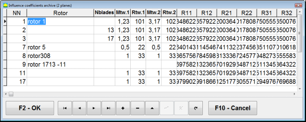
Fig. 7.42. The second page of the working window with balancing coefficients in 2 planes.
Change correction planes
""F5 – Change correction planes"دکمهی «» زمانی استفاده میشود که نیاز به تغییر موقعیت صفحات اصلاح باشد، یا زمانی که محاسبهی مجدد جرمها و زوایای نصب وزنههای اصلاحی ضروری باشد.
This mode is primarily useful when balancing rotors of complex shape (for example, crankshafts).
وقتی این دکمه فشرده میشود، پنجره کار ""Recalculation of correction weights mass and angle to other correction planes"" روی صفحه نمایش کامپیوتر نمایش داده میشود.
In this working window, you should select one of the 4 possible options by clicking corresponding picture.
صفحات تصحیح اصلی (H1 و H2) با رنگ سبز و صفحات تصحیح جدید (K1 و K2) که در اینجا بازشماری شدهاند، با رنگ قرمز مشخص شدهاند.
سپس، در ""Calculation data"بخش "، اطلاعات درخواستی، از جمله موارد زیر را وارد کنید:
- فاصله بین صفحات تصحیح مربوطه (a، b، c)؛
- مقادیر جدید شعاع نصب وزنههای اصلاحی روی روتور (R1 '، R2').
پس از وارد کردن داده ها، باید دکمه را فشار دهید ""F9-calculate"
نتایج محاسبه (جرمهای M1، M2 و زوایای نصب وزنههای اصلاحی f1، f2) در بخش مربوطه از این پنجره کاری نمایش داده میشوند.
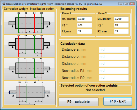
شکل ۷.۴۳ تغییر صفحات تصحیح. محاسبه مجدد جرم و زاویه تصحیح به سایر صفحات تصحیح.
ضریب تعادل ذخیره شده در ۲ صفحه
Saved coeff. balancing can be performed on a machine for which balancing coefficients have already been determined and saved in the computer memory.
⚠️ توجه! When re-balancing, the vibration sensors and the phase angle sensor must be installed in the same way as during the initial balancing.
ورود دادههای اولیه برای متعادلسازی مجدد از "" آغاز میشود."بالانس دو صفحهای. تنظیمات بالانس".
در این حالت، در ""Influence coefficients"بخش "، را انتخاب کنید""Saved coeff.""مورد. در این حالت، پنجره""Influence coefficients archive (2planes)"" ظاهر خواهد شد، که در آن بایگانی ضرایب متعادلسازی قبلاً تعیینشده ذخیره میشود.
با استفاده از دکمههای کنترل "►" یا "◄" در جدول این بایگانی، میتوانید رکورد مورد نظر را با ضرایب متعادلکننده دستگاه مورد علاقه ما انتخاب کنید. سپس، برای استفاده از این دادهها در اندازهگیریهای فعلی، دکمه ""F2 – OK"دکمهی "" را فشار دهید و به پنجرهی کاری قبلی برگردید.
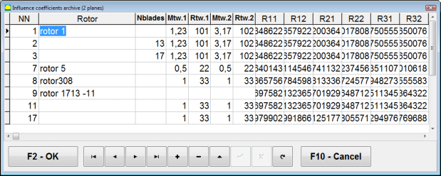
Fig. 7.44. The second page of the working window with balancing coefficients in 2 planes.
پس از آن، محتویات تمام پنجرههای دیگرِ ""ایجاد تعادل در ۲ pl. دادههای منبع"" به طور خودکار پر می شود.
Saved coeff. Balancing
"Saved coeff."بالانس کردن فقط به یک شروع تنظیم و حداقل یک شروع آزمایشی دستگاه بالانس نیاز دارد.».
Vibration measurement at the tuning start (Run # 0) از دستگاه در ""Balancing in 2 planes"پنجره کاری با جدولی از نتایج متعادلسازی در» Run # 0 section.
⚠️ توجه! Before starting the measurement, it is necessary to turn on the rotation of the rotor of the balancing machine and make sure that it has entered the operating mode with a stable speed.
To measure vibration parameters in the Run # 0 بخش، روی ""F7 – Run#0"دکمه " (یا کلید F7 را روی صفحه کلید کامپیوتر فشار دهید).
The results of measuring the rotor speed (RPM), as well as the value of the components of the RMS (VО1, VО2) and phases (F1, F2) of the 1x vibration appear in the corresponding fields of the Run # 0 section.
در همان زمان، ""Result"" برگه باز میشود، که نتایج محاسبه پارامترهای وزنههای اصلاحی را که باید روی روتور نصب شوند تا عدم تعادل آن را جبران کنند، نمایش میدهد.
علاوه بر این، در صورت استفاده از سیستم مختصات قطبی، صفحه نمایش مقادیر جرم و زوایای نصب وزنههای اصلاحی را نشان میدهد.
In the case of decomposition of corrective weights on the blades, the numbers of the blades of the balancing rotor and the mass of weight that need to be installed on them are displayed.
Further, the balancing process is carried out in accordance with the recommendations set out in section 7.6.1.2. for primary balancing.
⚠️ توجه!
- After completion of the measurement process after the second start of the balanced machine stop the rotation of its rotor and remove the previously set trial weight. Only then you can begin to install (or remove) correction weight on the rotor.
- Counting the angular position of the place of adding (or removing) of the correction weight from the rotor is carried out on the installation site of trial weight in the polar coordinate system. Counting direction coincides with the direction of the angle of rotor rotation.
- در صورت متعادلسازی روی پرهها - پره روتور متعادل، که به عنوان موقعیت ۱ تعیین شده است، با محل نصب وزنه آزمایشی منطبق است. جهت شماره مرجع پره که روی صفحه نمایش کامپیوتر نشان داده شده است، در جهت چرخش روتور انجام میشود.
- در این نسخه از برنامه، به طور پیشفرض پذیرفته شده است که وزنه اصلاحی روی روتور اضافه شود. برچسب ایجاد شده در قسمت "Addition" این موضوع را تأیید میکند. در صورت اصلاح عدم تعادل با برداشتن وزنه (به عنوان مثال با سوراخکاری)، لازم است برچسبی در قسمت "Removal" ایجاد شود، سپس موقعیت زاویهای وزنه اصلاحی به طور خودکار روی ۱۸۰ درجه تغییر میکند.
حذف خروج از مرکز مندرل (متعادلسازی شاخص) - دو صفحه
If during balancing the rotor is installed in a cylindrical mandrel, then the eccentricity of the mandrel may introduce an additional error. To eliminate this error, the rotor should be deployed in the mandrel 180 degrees and carry out an additional start. This is called index balancing.
To carry out index balancing, a special option is provided in the Balanset-1A program. When checked Mandrel eccentricity elimination an additional RunEcc section appears in the balancing window.
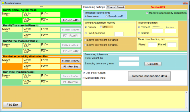
Fig. 7.45. The working window for Index balancing.
After running Run # 2 (Trial mass Plane 2), a window will appear
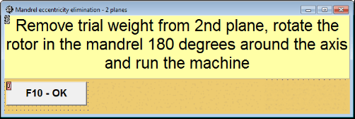
Fig. 7.46. Attention windows
پس از نصب روتور با چرخش ۱۸۰ درجه، باید Run Ecc تکمیل شود. برنامه به طور خودکار عدم تعادل واقعی روتور را بدون تأثیر بر خروج از مرکز مندرل محاسبه میکند.
۷.۶ حالت نمودارها
کار در حالت "نمودارها" از پنجره اولیه (شکل 7.1 را ببینید) با فشار دادن "F8 سپس پنجرهای با عنوان "اندازهگیری ارتعاش در دو کانال. نمودارها" باز میشود (شکل ۷.۱۹ را ببینید).

شکل 7.47. پنجره عملیاتی "اندازهگیری ارتعاش در دو کانال. نمودارها".
While working in this mode it is possible to plot four versions of vibration chart.
The first version allows to get a timeline function of the overall vibration (of vibration velocity) on the first and second measuring channels.
The second version allows you to get graphs of vibration (of vibration velocity), which occurs on rotation frequency and its higher harmonical components.
These graphs are obtained as a result of the synchronous filtering of the overall vibration time function.
The third version provides vibration charts with the results of the harmonical analysis.
The fourth version allows to get a vibration chart with the results of the spectrum analysis.
نمودارهای ارتعاش کلی
برای رسم نمودار کلی ارتعاش در پنجره عملیاتی ""Measurement of vibration on two channels. Charts""انتخاب حالت عملیاتی ضروری است""overall vibration"با کلیک روی دکمه مربوطه، اندازهگیری ارتعاش را در کادر "مدت زمان، بر حسب ثانیه" با کلیک روی دکمه «▼» تنظیم کنید و از لیست کشویی، مدت زمان مورد نظر برای فرآیند اندازهگیری را انتخاب کنید که میتواند برابر با ۱، ۵، ۱۰، ۱۵ یا ۲۰ ثانیه باشد؛;
پس از آمادگی، دکمه "" را فشار دهید (کلیک کنید)"F9دکمه "اندازهگیری» را فشار دهید، سپس فرآیند اندازهگیری ارتعاش به طور همزمان در دو کانال آغاز میشود.
After completion of the measurement process in the operating window appear charts of time function of the overall vibration of the first (red) and the second (green) channels (see. Fig. 7.47).
On these charts time is plotted on X-axis and the amplitude of the vibration velocity (mm/sec) is plotted on Y-axis.
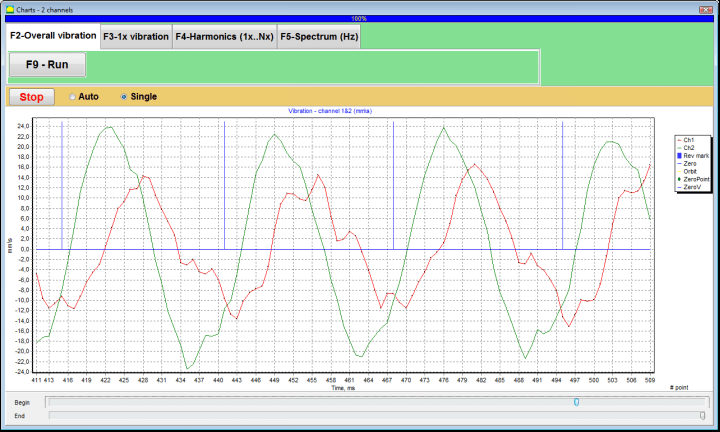
شکل ۷.۴۸. پنجره عملیاتی برای خروجی تابع زمان نمودارهای ارتعاش کلی
There are also marks (blue-colored) in these graphs connecting charts of overall vibration with the rotation frequency of the rotor. In addition, each mark indicates beginning (end) of the next revolution of the rotor.
In need of the scale change of the chart on X-axis the slider, pointed by an arrow on fig. 7.20, can be used.
نمودارهای ارتعاش ۱x
برای رسم نمودار ارتعاش ۱x در پنجره عملیاتی ""Measurement of vibration on two channels. Charts""انتخاب حالت عملیاتی ضروری است""1x vibration"با کلیک روی دکمه مربوطه ".
سپس پنجره عملیاتی "1x vibration" ظاهر میشود.
دکمه " را فشار دهید (کلیک کنید)"F9دکمه "اندازهگیری» را فشار دهید، سپس فرآیند اندازهگیری ارتعاش به طور همزمان در دو کانال آغاز میشود.
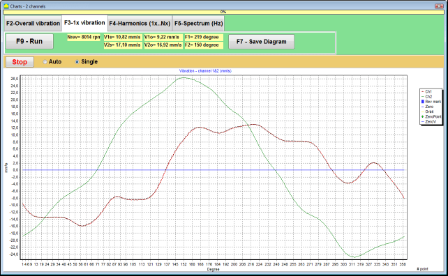
شکل ۷.۴۹. پنجره عملیاتی برای خروجی نمودارهای ارتعاش ۱x.
After completion of the measurement process and mathematical calculation of results (synchronous filtering of the time function of the overall vibration) on display in the main window on a period equal to one revolution of the rotor appear charts of the 1x vibration on two channels.
In this case, a chart for the first channel is depicted in red and for the second channel in green. On these charts angle of the rotor revolution is plotted (from mark to mark) on X-axis and the amplitude of the vibration velocity (mm/sec) is plotted on Y-axis.
علاوه بر این، در قسمت بالای پنجره کار (در سمت راست دکمه ""F9 - اندازهگیری"") مقادیر عددی اندازهگیریهای ارتعاش هر دو کانال، مشابه مقادیری که در ""Vibration meter"حالت "، نمایش داده میشوند.
In particular: RMS value of the overall vibration (V1s, V2s), the magnitude of RMS (V1o, V2o) and phase (Fi, Fj) of the 1x vibration and rotor speed (Nrev).
نمودارهای ارتعاش به همراه نتایج تحلیل هارمونیک
برای رسم نمودار با نتایج تحلیل هارمونیک در پنجره عملیاتی ""Measurement of vibration on two channels. Charts""انتخاب حالت عملیاتی ضروری است""Harmonical analysis"با کلیک روی دکمه مربوطه ".
سپس یک پنجره عملیاتی برای خروجی همزمان نمودارهای تابع موقت و طیف جنبههای هارمونیکی ارتعاش که دوره تناوب آنها برابر یا مضربی از فرکانس چرخش روتور است، ظاهر میشود.
Attention!
When operating in this mode it is necessary to use the phase angle sensor which synchronizes the measurement process with the rotor frequency of the machines to which the sensor is set.
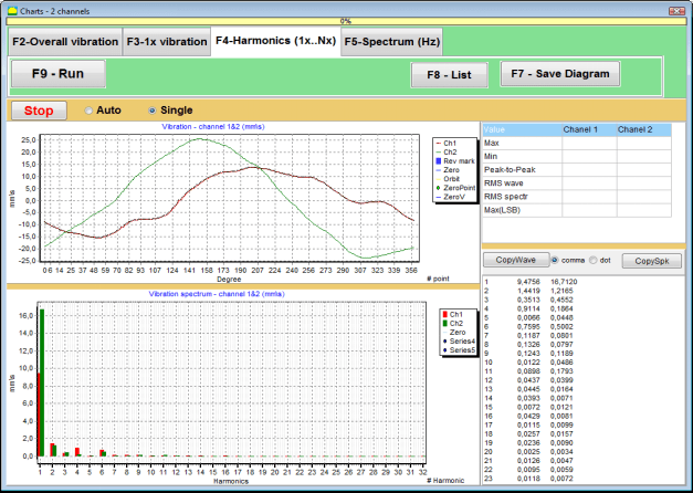
شکل ۷.۵۰. هارمونیکهای پنجره عملیاتی ارتعاش ۱x.
پس از آمادگی، دکمه "" را فشار دهید (کلیک کنید)"F9دکمه "اندازهگیری» را فشار دهید، سپس فرآیند اندازهگیری ارتعاش به طور همزمان در دو کانال آغاز میشود.
پس از اتمام فرآیند اندازهگیری، نمودارهای تابع زمان (نمودار بالاتر) و هارمونیکهای ارتعاش ۱x (نمودار پایینتر) در پنجره عملیاتی ظاهر میشوند.
The number of harmonic components is plotted on X-axis and RMS of the vibration velocity (mm/sec) is plotted on Y-axis.
نمودارهای حوزه زمان و طیف ارتعاش
برای رسم نمودار طیف از "" استفاده کنید."طیف F5"برگه ":
سپس یک پنجره عملیاتی برای خروجی همزمان نمودارهای موج و طیف ارتعاش ظاهر میشود.

شکل ۷.۵۱. پنجره عملیاتی برای خروجی طیف ارتعاش.
پس از آمادگی، دکمه "" را فشار دهید (کلیک کنید)"F9دکمه "اندازهگیری» را فشار دهید، سپس فرآیند اندازهگیری ارتعاش به طور همزمان در دو کانال آغاز میشود.
پس از اتمام فرآیند اندازهگیری، نمودارهای تابع زمان (نمودار بالاتر) و طیف ارتعاش (نمودار پایینتر) در پنجره عملیاتی ظاهر میشوند.
The vibration frequency is plotted on X-axis and RMS of the vibration velocity (mm/sec) is plotted on Y-axis.
In this case, a chart for the first channel is depicted in red and for the second channel in green.
۸. دستورالعملهای کلی در مورد نحوهی کار و نگهداری دستگاه
۸.۱ معیارهای کیفیت متعادل (استاندارد ISO 2372)
کیفیت بالانس را میتوان با استفاده از سطوح ارتعاش تعیینشده توسط استاندارد ISO 2372 ارزیابی کرد. جدول زیر سطوح ارتعاش قابل قبول برای کلاسهای مختلف ماشینآلات را نشان میدهد:
| کلاس ماشین | Good (میلیمتر بر ثانیه RMS) |
قابل قبول (میلیمتر بر ثانیه RMS) |
هنوز قابل قبول است (میلیمتر بر ثانیه RMS) |
غیرقابل قبول (میلیمتر بر ثانیه RMS) |
|---|---|---|---|---|
| کلاس ۱ ماشینهای کوچک روی پایههای سفت و سخت (موتورهای تا ۱۵ کیلووات) |
< 0.7 | 0.7 - 1.8 | 1.8 - 4.5 | > 4.5 |
| کلاس ۲ ماشینهای متوسط بدون پایه (موتورهای ۱۵-۷۵ کیلووات)، مکانیزمهای محرک تا ۳۰۰ کیلووات |
< 1.1 | 1.1 - 2.8 | 2.8 - 7.1 | > 7.1 |
| کلاس ۳ ماشینهای بزرگ روی پایههای سفت و سخت (تجهیزات بالای ۳۰۰ کیلووات) |
< 1.8 | 1.8 - 4.5 | 4.5 - 11 | > 11 |
| کلاس ۴ ماشینهای بزرگ روی پایههای سبک (تجهیزات بالای ۳۰۰ کیلووات) |
< 2.8 | 2.8 - 7.1 | 7.1 - 18 | > 18 |
توجه: این مقادیر راهنمایی برای ارزیابی کیفیت بالانس ارائه میدهند. همیشه به مشخصات خاص سازنده تجهیزات و استانداردهای مربوطه برای کاربرد خود مراجعه کنید.
۸.۲ الزامات نگهداری
🔧 نگهداری منظم
- ✓کالیبراسیون منظم سنسورها طبق مشخصات سازنده
- ✓سنسورها را تمیز و عاری از ذرات مغناطیسی نگه دارید
- ✓تجهیزات را در مواقع عدم استفاده در جعبه محافظ نگهداری کنید
- ✓محافظت از حسگر لیزر در برابر گرد و غبار و رطوبت
- ✓اتصالات کابل را مرتباً از نظر فرسودگی یا آسیب بررسی کنید
- ✓نرمافزار را طبق توصیه سازنده بهروزرسانی کنید
- ✓نسخههای پشتیبان از دادههای مهم مربوط به تعادل را نگه دارید
📋 استانداردهای نگهداری اتحادیه اروپا
نگهداری تجهیزات باید مطابق با موارد زیر باشد:
- استاندارد ایزو ۹۰۰۱: الزامات سیستمهای مدیریت کیفیت
- EN 13306: اصطلاحات و تعاریف تعمیر و نگهداری
- EN 15341: شاخصهای کلیدی عملکرد تعمیر و نگهداری
- بازرسیهای ایمنی منظم طبق دستورالعمل ماشینآلات اتحادیه اروپا
پیوست ۱. بالانس روتور
روتور جسمی است که حول یک محور خاص میچرخد و توسط سطوح یاتاقان خود در تکیهگاهها نگه داشته میشود. سطوح یاتاقان روتور، وزنها را از طریق یاتاقانهای غلتشی یا کشویی به تکیهگاهها منتقل میکنند. هنگام استفاده از اصطلاح "سطح یاتاقان"، ما صرفاً به یاتاقان* یا سطوح جایگزین یاتاقان اشاره میکنیم.
یاتاقان (در آلمانی به معنی "میله"، "سوزن") - بخشی از یک شفت یا محور است که توسط یک نگهدارنده (جعبه یاتاقان) حمل میشود.
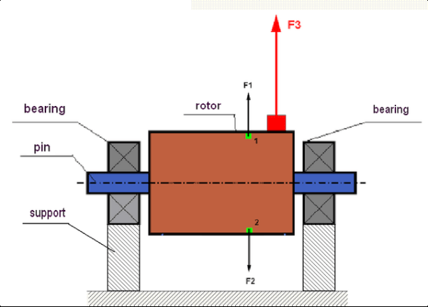
fig.1 Rotor and centrifugal forces.
In a perfectly balanced rotor, its mass is distributed symmetrically regarding the axis of the rotation. This means that any element of the rotor can correspond to another element located symmetrically in a relation to the axis of the rotation. During rotation, each rotor element acts upon by a centrifugal force directed in the radial direction (perpendicular to the axis of the rotor rotation). In a balanced rotor, the centrifugal force influencing any element of the rotor is balanced by the centrifugal force that influences the symmetrical element. For example, elements 1 and 2 (shown in fig.1 and colored in green) are influenced by centrifugal forces F1 and F2: equal in value and absolutely opposite in directions. This is true for all symmetrical elements of the rotor and thus the total centrifugal force influencing the rotor is equal to 0 the rotor is balanced. But if the symmetry of the rotor is broken (in Figure 1, the asymmetric element is marked in red), then the unbalanced centrifugal force F3 begins to act on the rotor.
هنگام چرخش، این نیرو همراه با چرخش روتور، جهت را تغییر میدهد. بار دینامیکی حاصل از این نیرو به یاتاقانها منتقل میشود که منجر به سایش سریع آنها میشود. علاوه بر این، تحت تأثیر این نیروی متغیر، تغییر شکل چرخهای در تکیهگاهها و فونداسیونی که روتور روی آن ثابت شده است، رخ میدهد که باعث ایجاد لرزش میشود. برای از بین بردن عدم تعادل روتور و لرزش همراه آن، لازم است جرمهای متعادلکنندهای تنظیم شود که تقارن روتور را بازیابی کند.
Rotor balancing is an operation to eliminate imbalance by adding balancing masses.
The task of balancing is to find the value and places (angle) of the installation of one or more balancing masses.
انواع روتورها و عدم تعادل
Considering the strength of the rotor material and the magnitude of the centrifugal forces influencing it, the rotors can be divided into two types: rigid and flexible.
روتورهای صلب در شرایط عملیاتی تحت تأثیر نیروی گریز از مرکز ممکن است کمی تغییر شکل دهند، اما بنابراین میتوان از تأثیر این تغییر شکل در محاسبات صرف نظر کرد.
Deformation of flexible rotors on the other hand should never be neglected. The deformation of flexible rotors complicates the solution for the balancing problem and requires the use of some other mathematical models in comparison with the task of balancing rigid rotors. It is important to mention that the same rotor at low speeds of rotation can behave like rigid one and at high speeds it will behave like flexible one. Further on we will consider the balancing of rigid rotors only.
بسته به توزیع جرمهای نامتعادل در طول روتور، دو نوع نامتعادلی قابل تشخیص است - استاتیک و دینامیک. همین امر در مورد بالانس روتور استاتیک و دینامیک نیز صدق میکند.
عدم تعادل استاتیک روتور بدون چرخش آن رخ میدهد. به عبارت دیگر، وقتی روتور تحت تأثیر جاذبه قرار دارد، در حالت سکون است و علاوه بر این، "نقطه سنگین" را به سمت پایین میچرخاند. نمونهای از روتور با عدم تعادل استاتیک در شکل 2 ارائه شده است.

Fig.2
The dynamic imbalance occurs only when the rotor spins.
An example of a rotor with the dynamic imbalance is presented in Fig.3.
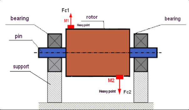
Fig.3. Dynamic imbalance of rotor – couple of the centrifugal forces
در این حالت، جرمهای مساوی و نامتعادل M1 و M2 در سطوح مختلف - در مکانهای مختلف در امتداد طول روتور - قرار دارند. در حالت استاتیک، یعنی زمانی که روتور نمیچرخد، روتور فقط ممکن است تحت تأثیر جاذبه قرار گیرد و بنابراین جرمها یکدیگر را متعادل میکنند. در دینامیک، هنگامی که روتور در حال چرخش است، جرمهای M1 و M2 تحت تأثیر نیروهای گریز از مرکز FЎ1 و FЎ2 قرار میگیرند. این نیروها از نظر مقدار برابر و در جهت مخالف هستند. با این حال، از آنجایی که آنها در مکانهای مختلف در امتداد طول شفت قرار دارند و در یک خط نیستند، نیروها یکدیگر را جبران نمیکنند. نیروهای FЎ1 و FЎ2 گشتاوری ایجاد میکنند که بر روتور عمل میکند. به همین دلیل است که این عدم تعادل نام دیگری "لحظهای" دارد. بر این اساس، نیروهای گریز از مرکز جبران نشده بر روی تکیهگاههای یاتاقان عمل میکنند که میتوانند به طور قابل توجهی از نیروهایی که ما به آنها تکیه کردیم فراتر روند و همچنین عمر مفید یاتاقانها را کاهش دهند.
از آنجایی که این نوع عدم تعادل فقط در حالت دینامیکی و در حین چرخش روتور رخ میدهد، به آن دینامیکی میگویند. نمیتوان آن را در بالانس استاتیک (یا به اصطلاح "روی تیغهها") یا به هر روش مشابه دیگری از بین برد. برای از بین بردن عدم تعادل دینامیکی، لازم است دو وزنه جبرانکننده تنظیم شود که گشتاوری برابر با مقدار و در جهت مخالف گشتاور ناشی از جرمهای M1 و M2 ایجاد کنند. جرمهای جبرانکننده لزوماً نباید در مقابل جرمهای M1 و M2 نصب شوند و از نظر مقدار با آنها برابر باشند. مهمترین چیز این است که آنها گشتاوری ایجاد کنند که درست در لحظه عدم تعادل، گشتاور را به طور کامل جبران کند.
به طور کلی، جرمهای M1 و M2 ممکن است با یکدیگر برابر نباشند، بنابراین ترکیبی از عدم تعادل استاتیکی و دینامیکی وجود خواهد داشت. از نظر تئوری ثابت شده است که برای از بین بردن عدم تعادل یک روتور صلب، نصب دو وزنه با فاصله در امتداد طول روتور ضروری و کافی است. این وزنهها هم گشتاور ناشی از عدم تعادل دینامیکی و هم نیروی گریز از مرکز ناشی از عدم تقارن جرم نسبت به محور روتور (عدم تعادل استاتیکی) را جبران میکنند. طبق معمول، عدم تعادل دینامیکی برای روتورهای بلند، مانند شفتها، و عدم تعادل استاتیکی برای روتورهای باریک معمول است. با این حال، اگر روتور باریک نسبت به محور کج نصب شود یا بدتر از آن، تغییر شکل داده شود (به اصطلاح "لرزش چرخ")، در این حالت از بین بردن عدم تعادل دینامیکی دشوار خواهد بود (شکل 4 را ببینید)، زیرا تنظیم وزنههای اصلاحکننده که گشتاور جبرانکننده مناسب را ایجاد میکنند، دشوار است.
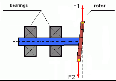
Fig.4 Dynamic balancing of the wobbling wheel
از آنجایی که شانه باریک روتور گشتاور کوتاهی ایجاد میکند، ممکن است نیاز به وزنههای اصلاحکننده با جرم زیاد باشد. اما در عین حال، یک به اصطلاح "عدم تعادل القایی" اضافی نیز وجود دارد که با تغییر شکل روتور باریک تحت تأثیر نیروهای گریز از مرکز از جرمهای اصلاحکننده مرتبط است.
See the example:
"دستورالعملهای روشمند در مورد بالانس روتورهای صلب" ISO 1940-1:2003 Mechanical vibration – Balance quality requirements for rotors in a constant (rigid) state – Part 1: Specification and verification of balance tolerances
This is visible for narrow fan wheels, which, in addition to the power imbalance, also influences an aerodynamic imbalance. And it is important to bear in mind that the aerodynamic imbalance, in fact the aerodynamic force, is directly proportional to the angular velocity of the rotor, and to compensate it, the centrifugal force of the correcting mass is used, which is proportional to the square of the angular velocity. Therefore, the balancing effect may only occur at a specific balancing frequency. At other speeds there would be an additional gap. The same can be said about electromagnetic forces in an electromagnetic motor, which are also proportional to the angular velocity. In other words it is impossible to eliminate all causes of vibration of the mechanism by any means of balancing.
مبانی ارتعاش
ارتعاش واکنشی از طراحی مکانیزم به اثر نیروی تحریک چرخهای است. این نیرو میتواند ماهیت متفاوتی داشته باشد.
- نیروی گریز از مرکز ناشی از عدم تعادل روتور، نیرویی جبران نشده است که بر "نقطه سنگین" تأثیر میگذارد. به ویژه این نیرو و همچنین ارتعاش ناشی از آن با بالانس روتور حذف میشوند.
- نیروهای متقابل، که ماهیت "هندسی" دارند و از اشتباهات در ساخت و نصب قطعات جفت شونده ناشی میشوند. این نیروها میتوانند به عنوان مثال به دلیل گرد نبودن محور شفت، اشتباهات در پروفیل دندانه در چرخ دندهها، موجدار بودن شیارهای یاتاقان، عدم همترازی شفتهای جفت شونده و غیره رخ دهند. در صورت گرد نبودن گردنها، محور شفت بسته به زاویه چرخش شفت تغییر مکان میدهد. اگرچه این ارتعاش در سرعت روتور آشکار میشود، اما حذف آن با بالانس تقریباً غیرممکن است.
- Aerodynamic forces arising from the rotation of the impeller fans and other blade mechanisms. Hydrodynamic forces arising from the rotation of hydraulic pump impellers, turbines, etc.
- نیروهای الکترومغناطیسی ناشی از عملکرد ماشینهای الکتریکی در نتیجه، به عنوان مثال، به دلیل عدم تقارن سیمپیچهای روتور، وجود دورهای اتصال کوتاه و غیره.
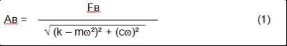
The magnitude of vibration (for example, its amplitude AB) depends not only on the magnitude of the excitation force Fт acting on the mechanism with the circular frequency ω, but also on the stiffness k of the structure of the mechanism, its mass m, and damping coefficient C.
Various types of sensors can be used to measure vibration and balance mechanisms, including:
- absolute vibration sensors designed to measure vibration acceleration (accelerometers) and vibration velocity sensors;
- حسگرهای ارتعاش نسبی جریان گردابی یا خازنی، طراحی شده برای اندازهگیری ارتعاش.
In some cases (when the structure of the mechanism allows it) sensors of force can also be used to examine its vibration weight.
Particularly, they are widely used to measure the vibration weight of the supports of hardbearing balancing machines.
Therefore vibration is the reaction of the mechanism to the influence of external forces. The amount of vibration depends not only on the magnitude of the force acting on the mechanism, but also on the rigidity of the mechanism. Two forces with the same magnitude can lead to different vibrations. In mechanisms with a rigid support structure, even with the small vibration, the bearing units can be significantly influenced by dynamic weights. Therefore, when balancing mechanisms with stiff legs apply the force sensors, and vibration (vibro accelerometers). Vibration sensors are only used on mechanisms with relatively pliable supports, right when the action of unbalanced centrifugal forces leads to a noticeable deformation of the supports and vibration. Force sensors are used in rigid supports even when significant forces arising from imbalance do not lead to significant vibration.
رزونانس سازه
We have previously mentioned that rotors are divided into rigid and flexible. The rigidity or flexibility of the rotor should not be confused with the stiffness or mobility of the supports (foundation) on which the rotor is located. The rotor is considered rigid when its deformation (bending) under the action of centrifugal forces can be neglected. The deformation of the flexible rotor is relatively large: it cannot be neglected.
در این مقاله ما فقط به بررسی تعادل روتورهای صلب میپردازیم. روتور صلب (غیر تغییر شکلپذیر) به نوبه خود میتواند روی تکیهگاههای صلب یا متحرک (انعطافپذیر) قرار گیرد. واضح است که این سختی/تحرک تکیهگاهها بسته به سرعت چرخش روتور و بزرگی نیروهای گریز از مرکز حاصل، نسبی است. مرز مرسوم، فرکانس نوسانات آزاد تکیهگاهها/فونداسیون روتور است. برای سیستمهای مکانیکی، شکل و فرکانس نوسانات آزاد توسط جرم و خاصیت ارتجاعی عناصر سیستم مکانیکی تعیین میشود. یعنی فرکانس نوسانات طبیعی یک ویژگی داخلی سیستم مکانیکی است و به نیروهای خارجی بستگی ندارد. تکیهگاهها با انحراف از حالت تعادل، به دلیل خاصیت ارتجاعی تمایل به بازگشت به موقعیت تعادل خود دارند. اما به دلیل اینرسی روتور عظیم، این فرآیند ماهیت نوسانات میرا دارد. این نوسانات، نوسانات خود سیستم روتور-تکیهگاه هستند. فرکانس آنها به نسبت جرم روتور و خاصیت ارتجاعی تکیهگاهها بستگی دارد.
When the rotor begins to rotate and the frequency of its rotation approaches the frequency of its own oscillations, the vibration amplitude increases sharply, which can even lead to the destruction of the structure.
There is a phenomenon of mechanical resonance. In the resonance region, a change in the speed of rotation by 100 rpm can lead to an increase in a vibration tenfold. In this case (in the resonance region) the vibration phase changes by 180°.
اگر طراحی مکانیزم ضعیف باشد و سرعت عملکرد روتور نزدیک به فرکانس طبیعی نوسانات باشد، عملکرد مکانیزم به دلیل ارتعاش غیرقابل قبول بالا غیرممکن میشود. روشهای استاندارد بالانس نیز غیرممکن هستند، زیرا پارامترها حتی با تغییر جزئی در سرعت چرخش به طور چشمگیری تغییر میکنند. روشهای ویژهای در زمینه بالانس رزونانس استفاده میشود، اما در این مقاله به خوبی شرح داده نشدهاند. میتوانید فرکانس نوسانات طبیعی مکانیزم را در حالت خروج (هنگامی که روتور خاموش است) یا با ضربه با تجزیه و تحلیل طیفی بعدی پاسخ سیستم به شوک تعیین کنید. "Balanset-1" امکان تعیین فرکانسهای طبیعی سازههای مکانیکی را با این روشها فراهم میکند.
For mechanisms whose operating speed is higher than the resonance frequency, that is, operating in the resonant mode, supports are considered as mobile ones and vibration sensors are used to measure, mainly vibration accelerometers that measure the acceleration of structural elements. For mechanisms operating in hard bearing mode, supports are considered as rigid. In this case, force sensors are used.
مدلهای خطی و غیرخطی سیستم مکانیکی
Mathematical models (linear) are used for calculations when balancing rigid rotors. The linearity of the model means that one model is directly proportionally (linearly) dependent on the other. For example, if the uncompensated mass on the rotor is doubled, then the vibration value will be doubled correspondingly. For rigid rotors you can use a linear model because such rotors are not deformed. It is no longer possible to use a linear model for flexible rotors. For a flexible rotor, with an increase of the mass of a heavy point during rotation, an additional deformation will occur, and in addition to the mass, the radius of the heavy point will also increase. Therefore, for a flexible rotor, the vibration will more than double, and the usual calculation methods will not work. Also, a violation of the linearity of the model can lead to a change in the elasticity of the supports at their large deformations, for example, when small deformations of the supports work some structural elements, and when large in the work include other structural elements. Therefore it is impossible to balance the mechanisms that are not fixed at the base, and, for example, are simply established on a floor. With significant vibrations, the unbalance force can detach the mechanism from the floor, thereby significantly changing the stiffness characteristics of the system. The engine legs must be securely fastened, bolted fasteners tightened, the thickness of the washers must provide sufficient rigidity, etc. With broken bearings, a significant displacement of the shaft and its impacts is possible, which will also lead to a violation of linearity and the impossibility of carrying out high-quality balancing.
Methods and devices for balancing
As mentioned above, balancing is the process of combining the main Central axis of inertia with the axis of rotation of the rotor.
The specified process can be executed in two ways.
The first method involves the processing of the rotor axles, which is performed in such a way that the axis passing through the centers of the section of the axles with the main Central axis of inertia of the rotor. This technique is rarely used in practice and will not be discussed in detail in this article.
The second (most common) method involves moving, installing or removing corrective masses on the rotor, which are placed in such a way that the axis of inertia of the rotor is as close as possible to the axis of its rotation.
Moving, adding or removing corrective masses during balancing can be done using a variety of technological operations, including: drilling, milling, surfacing, welding, screwing or unscrewing screws, burning with a laser beam or electron beam, electrolysis, electromagnetic welding, etc.
The balancing process can be performed in two ways:
- مجموعه روتورهای متعادل (در یاتاقانهای مخصوص خود)؛
- بالانس روتورها در ماشینهای بالانس.
To balance the rotors in their own bearings we usually use specialized balancing devices (kits), which allows us to measure the vibration of the balanced rotor at the speed of its rotation in a vector form, i.e. to measure both the amplitude and phase of vibration.
Currently, these devices are manufactured on the basis of microprocessor technology and (in addition to the measurement and analysis of vibration) provide automated calculation of the parameters of corrective weights that must be installed on the rotor to compensate its imbalance.
These devices include:
- واحد اندازهگیری و محاسبه، ساخته شده بر اساس کامپیوتر یا کنترلکننده صنعتی؛
- دو (یا بیشتر) حسگر ارتعاش؛
- حسگر زاویه فاز؛
- تجهیزات نصب سنسورها در تأسیسات؛
- نرمافزار تخصصی طراحی شده برای انجام یک چرخه کامل اندازهگیری پارامترهای عدم تعادل روتور در یک، دو یا چند صفحه اصلاح.
برای متعادل کردن روتورها در ماشینهای متعادلکننده، علاوه بر یک دستگاه متعادلکننده تخصصی (سیستم اندازهگیری ماشین)، لازم است یک "مکانیسم باز کردن" نیز وجود داشته باشد که برای نصب روتور روی تکیهگاهها و اطمینان از چرخش آن با سرعت ثابت طراحی شده باشد.
Currently, the most common balancing machines exist in two types:
- بیش از حد رزونانس (با تکیهگاههای انعطافپذیر)؛
- یاتاقان سخت (با تکیهگاههای صلب).
Over-resonant machines have a relatively pliable supports, made, for example, on the basis of the flat springs.
The natural oscillation frequency of these supports is usually 2-3 times lower than the speed of the balanced rotor, which is mounted on them.
Vibration sensors (accelerometers, vibration velocity sensors, etc.) are usually used to measure the vibration of the supports of a resonant machine.
In the hardbearing balancing machines are used relatively-rigid supports, natural oscillation frequencies of which should be 2-3 times higher than the speed of the balanced rotor.
Force sensors are usually used to measure the vibration weight on the supports of the machine.
The advantage of the hard bearing balancing machines is that they can be balanced at relatively low rotor speeds (up to 400-500 rpm), which greatly simplifies the design of the machine and its foundation, as well as increases the productivity and safety of balancing.
Balancing technique
⚠️ بالانس کردن فقط ارتعاشی را که ناشی از عدم تقارن توزیع جرم روتور نسبت به محور چرخش آن است، از بین میبرد. انواع دیگر ارتعاش را نمیتوان با بالانس کردن از بین برد!
Balancing is the subject to technically serviceable mechanisms, the design of which ensures the absence of resonances at the operating speed, securely fixed on the foundation, installed in serviceable bearings.
🚫 مکانیزم معیوب نیاز به تعمیر دارد و تنها پس از آن - نیاز به تعادل. در غیر این صورت، تعادل کیفی غیرممکن است.
Balancing cannot be a substitute for repair!
The main task of balancing is to find the mass and the place (angle) of installation of compensating weights, which are balanced by centrifugal forces.
As mentioned above, for rigid rotors it is generally necessary and sufficient to install two compensating weights. This will eliminate both the static and dynamic rotor imbalance. A general scheme of the vibration measurement during balancing looks like the following:
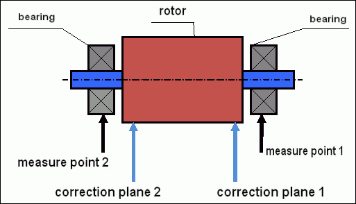
fig.5 Dynamic balancing – correction planes and measure points
Vibration sensors are installed on the bearing supports at points 1 and 2. The speed mark is fixed right on the rotor, a reflective tape is glued usually. The speed mark is used by the laser tachometer to determine the speed of the rotor and the phase of the vibration signal.
شکل 6. نصب سنسورها هنگام تعادل در دو صفحه، با استفاده از Balanset-1
1,2-vibration sensors, 3-phase, 4- USB measuring unit, 5-laptop
In most cases, dynamic balancing is carried out by the method of three starts. This method is based on the fact that test weights of an already-known mass are installed on the rotor in series in 1 and 2 planes; so the masses and the place of installation of balancing weights are calculated based on the results of changing the vibration parameters.
محل نصب وزنه، صفحه اصلاح نامیده میشود. معمولاً صفحات اصلاح در ناحیه تکیهگاههای یاتاقان که روتور روی آنها نصب شده است، انتخاب میشوند.
ارتعاش اولیه در اولین استارت اندازهگیری میشود. سپس، یک وزنه آزمایشی با جرم مشخص روی روتور و نزدیکتر به یکی از تکیهگاهها نصب میشود. سپس استارت دوم انجام میشود و پارامترهای ارتعاش را که باید به دلیل نصب وزنه آزمایشی تغییر کنند، اندازهگیری میکنیم. سپس وزنه آزمایشی در صفحه اول برداشته شده و در صفحه دوم نصب میشود. استارت سوم انجام میشود و پارامترهای ارتعاش اندازهگیری میشوند. هنگامی که وزنه آزمایشی برداشته میشود، برنامه به طور خودکار جرم و محل (زوایای) نصب وزنههای تعادل را محاسبه میکند.
The point in setting up test weights is to determine how the system responds to the imbalance change. When we know the masses and the location of the sample weights, the program can calculate the so-called influence coefficients, showing how the introduction of a known imbalance affects the vibration parameters. The coefficients of influence are the characteristics of the mechanical system itself and depend on the stiffness of the supports and the mass (inertia) of the rotor-support system.
For the same type of mechanisms of the same design, the coefficients of influence will be similar. You can save them in your computer memory and use them afterwards for balancing the same type of mechanisms without carrying out test runs, which greatly improves the performance of the balancing. We should also note that the mass of test weights should be chosen as such so that the vibration parameters vary markedly when installing test weights. Otherwise, the error in calculating the coefficients of the affect increases and the quality of balancing deteriorates.
راهنمای دستگاه Balanset-1 فرمولی ارائه میدهد که با استفاده از آن میتوانید بسته به جرم و سرعت چرخش روتور متعادل، جرم وزنه آزمایشی را تقریباً تعیین کنید. همانطور که از شکل 1 میتوانید بفهمید، نیروی گریز از مرکز در جهت شعاعی، یعنی عمود بر محور روتور، عمل میکند. بنابراین، حسگرهای ارتعاش باید طوری نصب شوند که محور حساسیت آنها نیز در جهت شعاعی باشد. معمولاً صلبیت فونداسیون در جهت افقی کمتر است، بنابراین ارتعاش در جهت افقی بیشتر است. بنابراین، برای افزایش حساسیت حسگرها باید طوری نصب شوند که محور حساسیت آنها نیز بتواند به صورت افقی هدایت شود. اگرچه هیچ تفاوت اساسی وجود ندارد. علاوه بر ارتعاش در جهت شعاعی، لازم است ارتعاش در جهت محوری، در امتداد محور چرخش روتور، کنترل شود. این ارتعاش معمولاً نه به دلیل عدم تعادل، بلکه به دلایل دیگری، عمدتاً به دلیل عدم تراز و ناهمراستایی شفتهای متصل از طریق کوپلینگ، ایجاد میشود. این ارتعاش با متعادلسازی از بین نمیرود، در این حالت ترازبندی لازم است. در عمل، معمولاً در چنین مکانیزمهایی عدم تعادل روتور و ناهمترازی شفتها وجود دارد که کار حذف ارتعاش را بسیار پیچیده میکند. در چنین مواردی، ابتدا باید مکانیزم را تراز و سپس بالانس کنید. (اگرچه با عدم تعادل گشتاور قوی، ارتعاش در جهت محوری نیز به دلیل "پیچش" سازه فونداسیون رخ میدهد).
دقت اندازهگیری و تحلیل خطا
درک دقت اندازهگیری برای عملیات بالانس حرفهای بسیار مهم است. Balanset-1A دقت اندازهگیری زیر را ارائه میدهد:
| پارامتر | فرمول دقت | مثال (برای مقادیر معمول) |
|---|---|---|
| سرعت ارتعاش RMS | ±(0.1 + 0.1×Vاندازهگیری شدهمیلیمتر بر ثانیه | برای ۵ میلیمتر بر ثانیه: ±۰.۶ میلیمتر بر ثانیه برای 10 میلیمتر بر ثانیه: ±1.1 میلیمتر بر ثانیه |
| فرکانس چرخش | ±(1 + 0.005×Nاندازهگیری شده) دور در دقیقه | برای ۱۰۰۰ دور در دقیقه: ±۶ دور در دقیقه برای ۳۰۰۰ دور در دقیقه: ±۱۶ دور در دقیقه |
| اندازهگیری فاز | ±۱ درجه | دقت ثابت در تمام سرعتها |
⚠️ برای تعادل دقیق بسیار مهم است
- !وزن آزمایشی باید باعث تغییر دامنه >20-30% شود و/یا تغییر فاز >20-30 درجه
- !اگر تغییرات کوچکتر باشند، خطاهای اندازهگیری به طور قابل توجهی افزایش مییابند
- !دامنه ارتعاش و پایداری فاز نباید بیش از 10-15% بین اندازهگیریها تغییر کند.
- !اگر تغییرات از ۱۵۱TP3T بیشتر شد، شرایط رزونانس یا مشکلات مکانیکی را بررسی کنید.
معیارهای ارزیابی کیفیت مکانیسمهای تعادل
Quality of rotor (mechanisms) balancing can be estimated in two ways. The first method involves comparing the value of the residual imbalance determined during the balancing with the tolerance for the residual imbalance. The specified tolerances for various classes of rotors installed in the standard ISO 1940-1-2007. «ارتعاش. الزامات مربوط به کیفیت بالانس روتورهای صلب. بخش 1. تعیین عدم تعادل مجاز".
با این حال، اجرای این تلرانسها نمیتواند به طور کامل قابلیت اطمینان عملیاتی مکانیزم مرتبط با دستیابی به حداقل سطح ارتعاش را تضمین کند. این به این دلیل است که ارتعاش مکانیزم نه تنها با مقدار نیروی مرتبط با عدم تعادل باقیمانده روتور آن تعیین میشود، بلکه به تعدادی از پارامترهای دیگر، از جمله: سختی K عناصر ساختاری مکانیزم، جرم M آن، ضریب میرایی و سرعت نیز بستگی دارد. بنابراین، برای ارزیابی ویژگیهای دینامیکی مکانیزم (از جمله کیفیت تعادل آن) در برخی موارد، توصیه میشود سطح ارتعاش باقیمانده مکانیزم که توسط تعدادی از استانداردها تنظیم میشود، ارزیابی شود.
The most common standard regulating permissible vibration levels of mechanisms is پیشنمایش ISO 10816-3:2009 ارتعاش مکانیکی – ارزیابی ارتعاش ماشین با اندازهگیری روی قطعات غیرچرخشی -- قسمت 3: ماشینهای صنعتی با توان اسمی بالای 15 کیلووات و سرعت اسمی بین 120 دور در دقیقه و 15000 دور در دقیقه هنگام اندازهگیری در محل.»
With its help, you can set the tolerance on all types of machines, taking into account the power of their electric drive.
In addition to this universal standard, there are a number of specialized standards developed for specific types of mechanisms. For example,
- ISO 14694:2003 "فنهای صنعتی - مشخصات کیفیت تعادل و سطوح ارتعاش"
- ISO 7919-1-2002 "ارتعاش ماشینآلات بدون حرکت رفت و برگشتی. اندازهگیریها روی شفتهای چرخان و معیارهای ارزیابی. راهنمای کلی.»
🛡️ ملاحظات ایمنی مهم برای انطباق با اتحادیه اروپا
- !ارزیابی ریسک مورد نیاز: قبل از عملیات بالانس، ارزیابی ریسک EN ISO 12100 را انجام دهید.
- !پرسنل واجد شرایط: فقط پرسنل آموزش دیده و دارای گواهینامه باید عملیات بالانس را انجام دهند
- !تجهیزات حفاظت فردی: همیشه از تجهیزات حفاظت فردی (PPE) مناسب طبق استاندارد EN 166 (محافظ چشم) و EN 352 (محافظ شنوایی) استفاده کنید.
- !رویههای اورژانسی: رویههای خاموش کردن اضطراری واضحی را تدوین کنید و اطمینان حاصل کنید که همه اپراتورها با آنها آشنا هستند.
- !مستندات: سوابق دقیق تمام عملیات تعادل را برای ردیابی و انطباق حفظ کنید.
اطلاعات انطباق و ایمنی اتحادیه اروپا
اعلامیه انطباق
بالانسر قابل حمل Balanset-1A با دستورالعملها و استانداردهای اتحادیه اروپا زیر مطابقت دارد:
| دستورالعمل/استاندارد اتحادیه اروپا | جزئیات انطباق | الزامات ایمنی |
|---|---|---|
| دستورالعمل ماشین آلات 2006/42/EC | الزامات ایمنی برای ماشین آلات و قطعات ایمنی | ارزیابی ریسک، دستورالعملهای ایمنی، نشان CE |
| دستورالعمل EMC 2014/30/EU | الزامات سازگاری الکترومغناطیسی | مصونیت در برابر تداخل الکترومغناطیسی |
| دستورالعمل RoHS 2011/65/EU | محدودیت مواد خطرناک | اجزای بدون سرب، بدون جیوه، بدون کادمیوم |
| دستورالعمل WEEE 2012/19/EU | ضایعات تجهیزات الکتریکی و الکترونیکی | روشهای صحیح دفع و بازیافت |
| استاندارد EN ISO 12100:2010 | ایمنی ماشین آلات - اصول کلی طراحی | ارزیابی ریسک و کاهش ریسک |
| EN 60825-1:2014 | ایمنی محصولات لیزری - بخش 1 | الزامات ایمنی لیزر کلاس ۲ |
| استاندارد EN ISO 14120:2015 | نگهبانان - الزامات عمومی | حفاظت در برابر خطرات ماشین آلات دوار |
استانداردهای ایمنی برق
- ✓استاندارد EN 61010-1: الزامات ایمنی برای تجهیزات الکتریکی برای اندازهگیری، کنترل و استفاده آزمایشگاهی
- ✓EN 60950-1: ایمنی تجهیزات فناوری اطلاعات (دستگاههای دارای منبع تغذیه USB)
- ✓سری IEC 61000: استانداردهای سازگاری الکترومغناطیسی
- ✓ولتاژ عملیاتی: ۵ ولت DC از طریق USB (ولتاژ بسیار پایین)
- ✓مصرف برق: کمتر از ۲.۵ وات
- ✓کلاس حفاظتی: IP20 (برای استفاده در محیط داخلی)
ایمنی تجهیزات دوار
⚠️ رویههای ایمنی اجباری (EN ISO 12100)
هشدار: هنگام کار با ماشین آلات دوار، موارد ایمنی زیر را رعایت کنید:
- !استاندارد EN ISO 14118: جلوگیری از روشن شدن غیرمنتظره - قبل از نصب سنسور از رویههای قفل/برچسبگذاری استفاده کنید
- !استاندارد EN ISO 14120: اطمینان حاصل کنید که تمام تجهیزات چرخشی به درستی محافظت میشوند
- !استاندارد EN ISO 13857: حداقل فاصله ایمن را از قطعات چرخان (۵۰۰ میلیمتر برای بدن، ۱۲۰ میلیمتر برای انگشتان) حفظ کنید.
- !تجهیزات حفاظت فردی: از عینک ایمنی مطابق استاندارد EN 166 و محافظ شنوایی مطابق استاندارد EN 352 استفاده کنید و از پوشیدن لباسهای گشاد خودداری کنید.
- !هرگز سنسورها یا وزنههای آزمایشی را روی ماشینآلات دوار در حال حرکت نصب نکنید.
- !قبل از نصب سنسور، مطمئن شوید که دستگاه کاملاً متوقف و ایمن شده است.
- !توقف اضطراری: باید در فاصله ۳ متری از موقعیت اپراتور قابل دسترسی باشد
- !فقط پرسنل واجد شرایط و دارای گواهینامه باید عملیات بالانس را انجام دهند
طبقه بندی ایمنی لیزر
🔴 دستگاه لیزر کلاس 2 (EN 60825-1:2014)
- طول موج: ۶۵۰ نانومتر (نور مرئی قرمز)
- حداکثر توان خروجی: کمتر از ۱ میلیوات
- قطر پرتو: ۳-۵ میلیمتر در فاصله ۱۰۰ میلیمتری
- واگرایی: < 1.5 میلیراد
- طبقه بندی ایمنی: ایمن برای چشم در برابر قرار گرفتن در معرض لحظه ای (<0.25 ثانیه)
- برچسب گذاری مورد نیاز: "تابش لیزر - به پرتو آن خیره نشوید - محصول لیزری کلاس ۲"
- کلاس دسترسی: نامحدود (دسترسی عمومی مجاز است)
دستورالعملهای ایمنی لیزر:
- هرگز عمداً به پرتو لیزر خیره نشوید
- لیزر را به سمت افراد، وسایل نقلیه یا هواپیما نشانه نگیرید
- از مشاهده پرتو لیزر با ابزارهای نوری (تلسکوپ، دوربین دوچشمی) خودداری کنید.
- مراقب بازتابهای آینهای از سطوح براق باشید
- خاموش کردن لیزر در مواقع عدم استفاده
- هرگونه حادثه مربوط به تماس با چشم را فوراً گزارش دهید
- برای قرار گرفتن در معرض طولانی مدت از عینک ایمنی لیزر (OD 2+ در 650 نانومتر) استفاده کنید.
دقت اندازهگیری و کالیبراسیون
| پارامتر | دقت | فرکانس کالیبراسیون |
|---|---|---|
| دامنه ارتعاش | ±5% از خواندن | سالانه یا بعد از ۱۰۰۰ ساعت |
| اندازهگیری فاز | ±۱ درجه | سالانه |
| سرعت چرخش | ±0.1% از خواندن | سالانه |
| حساسیت حسگر | ۱۳ میلیولت بر (میلیمتر بر ثانیه) ±۱۰۱TP3T | هنگام تعویض سنسورها |
انطباق با محیط زیست
- ✓محیط عملیاتی: ۵ تا ۵۰ درجه سانتیگراد، <85% RH غیر چگالشی
- ✓محیط نگهداری: -20 درجه سانتیگراد تا 70 درجه سانتیگراد، <95% RH غیر متراکم
- ✓ارتفاع: تا ارتفاع ۲۰۰۰ متر از سطح دریا
- ✓مقاومت در برابر لرزش: IEC 60068-2-6 (10-500 هرتز، شتاب 2g)
- ✓مقاومت در برابر ضربه: IEC 60068-2-27 (15 گرم، مدت زمان 11 میلیثانیه)
- ✓رتبهبندی آیپی: IP20 (محافظت در برابر اجسام جامد بزرگتر از 12 میلیمتر)
الزامات عملیاتی
- ✓اپراتورها باید طبق استانداردهای اتحادیه اروپا در زمینه ایمنی ماشین آلات آموزش ببینند.
- ✓ارزیابی ریسک طبق استاندارد EN ISO 12100 قبل از استفاده الزامی است.
- ✓تجهیزات را مطابق با مشخصات سازنده نگهداری کنید
- ✓هرگونه حادثه ایمنی یا نقص تجهیزات را فوراً گزارش دهید
- ✓سوابق دقیق تمام عملیات تعادل را برای قابلیت ردیابی حفظ کنید.
الزامات مستندسازی
برای رعایت الزامات اتحادیه اروپا، مدارک زیر را نگهداری کنید:
- ✓مستندسازی ارزیابی ریسک بر اساس استاندارد EN ISO 12100
- ✓سوابق و گواهینامههای آموزشی اپراتورها
- ✓گزارشهای کالیبراسیون و نگهداری تجهیزات
- ✓متعادلسازی سوابق عملیات با تاریخها، عملگرها و نتایج
- ✓گزارشهای حوادث ایمنی و اقدامات اصلاحی
- ✓مستندات اصلاح یا تعمیر تجهیزات
پشتیبانی فنی و خدمات
برای پشتیبانی فنی، خدمات کالیبراسیون و قطعات یدکی:
- ✓سازنده: Vibromera
- ✓مکان: Rua Alcaide de Faria 193، پورتو، پرتغال
- ✓وبسایت: https://vibromera.eu
- ✓زبانهای پشتیبانیشده: همه زبانهای اصلی. ارتباط متنی موجود است.
- ✓پوشش خدمات: ارسال به سراسر جهان موجود است
- ✓گارانتی: ۲۴ ماه از تاریخ خرید
- ✓خدمات کالیبراسیون: از طریق مراکز خدمات مجاز قابل تهیه است
