← Balanset-1A žinių bazė — visi skyriai
Komplekto sudėtis (Full Kit)
- Matavimo blokas (2 vibracijos kanalai + tachometro kanalas), maitinamas USB iš nešiojamojo kompiuterio
- 2 vibracijos jutikliai (akselerometrai) ant magnetų, 5 m kabelis (iki 10 m užsakymu)
- Lazerinis tachometras (optinis jutiklis) su magnetiniu stovu
- Elektroninės svarstyklės (iki 500 g, 0,1 g žingsnis)
- Atspindinti juostelė žymai
- Programinė įranga USB raktelyje
- Plastikinis dėklas
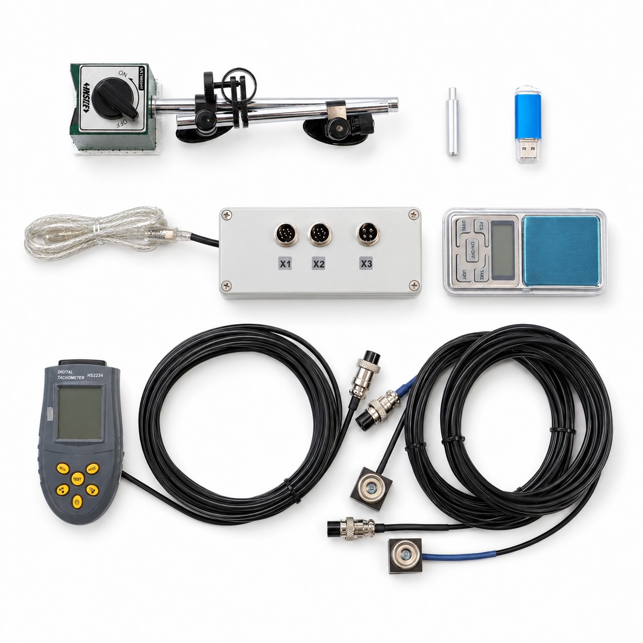
OEM versija tokia pati, bet be dėklo, magnetinio stovo ir svarstyklių. Nešiojamasis kompiuteris / planšetė neįeina į komplektą.
Smulkintuvų (mulčerių) bandomieji ir korekciniai svareliai dažnai sveria 0.5–1 kg, todėl praverčia svarstyklės iki 2 kg.
Pagrindinės specifikacijos
| Parametras | Vertė |
|---|---|
| Vibracijos greitis (RMS) | 0,02–80 mm/s |
| Dažnių diapazonas | 5 – 1000 Hz |
| RPM | 100 – 100 000 aps./min |
| Fazės tikslumas | ±1° |
| Balansavimo plokštumos | 1 arba 2 |
| Rotoriaus masė | metodo neriboja masė (realus rekordas — 24 000 kg rotorius) |
| kompiuteris | Windows 7/8/10/11, USB prievadas. Planšetės — tik su pilna Windows versija (Android/iOS neveiks) |
Praktinės pastabos:
- praktinis balansavimo diapazonas – apie 300–60,000 rpm;
- pagrindiniai guolių defektų dažniai (BPFO/BPFI) matomi spektre;
- labai lengviems rotoriams (dešimtys gramų) iki 0.02 mm/s skiriamoji geba pasiekiama didinant vidurkinimų skaičių.
Vibracijos jutikliai
- Tipas — akselerometrai (ADXL335 pagrindu), duodantys vibracijos greitį. Jiems reikia maitinimo iš prietaiso — todėl trijų laidų ekranuoti kabeliai.
- Matavimo ašis eina išilgai magneto, statmenai tvirtinimo paviršiui. Montuokite jutiklį taip, kad jo ašis būtų nukreipta radialiai, skersai sukimosi ašies, paprastai horizontaliai ant guolio korpuso. Montavimas ant galinio paviršiaus ašine kryptimi yra dažna klaida, dėl kurios balansavimo rezultatas nekonverguoja.
- X1 → 1 plokštuma, X2 → 2 plokštuma. Nesukeiskite kanalų: sukeitus jutiklius pasikeičia apskaičiuotų kampų kryptis.
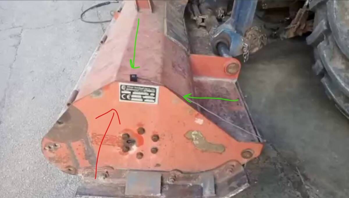
- Kabelis yra silpnoji vieta: jutiklį įtraukus į rotorių, dažniausiai nutrūksta jo kabelis. Nutieskite kabelius taip, kad jie negalėtų įsivelti.
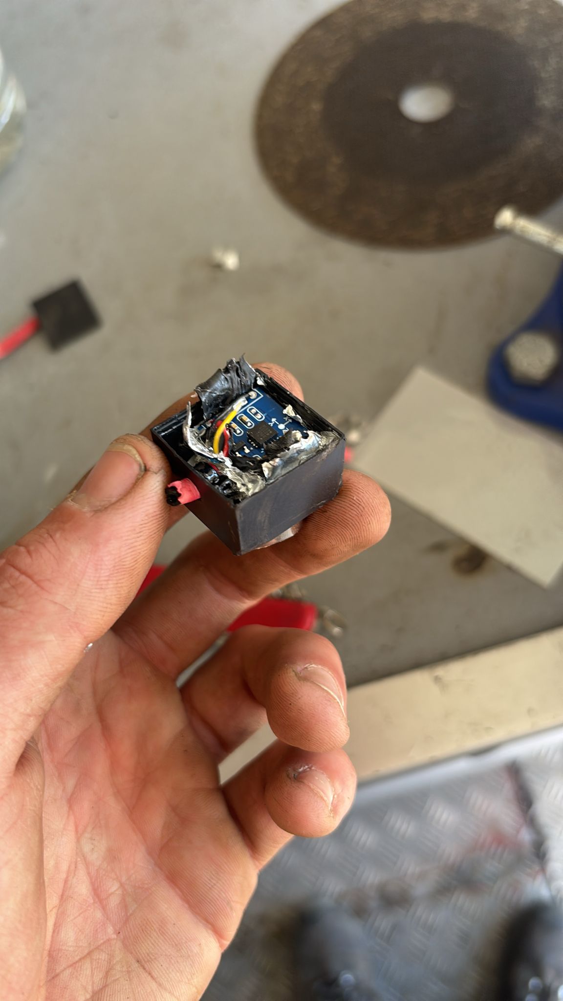
- Jutiklio tarnavimo laikas — 5–7 metai ar daugiau; metinė kalibracija nereikalinga.
Lazerinis tachometras
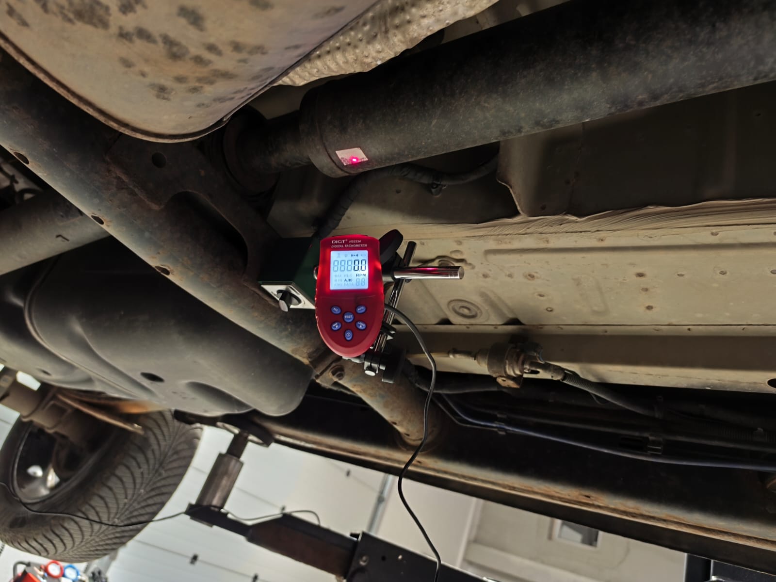
- Tachometras tvirtinamas prie magnetinio stovo, o jo lazerio spindulys nukreipiamas į ant rotoriaus priklijuotą atspindinčią žymą (juostos gabalėlį iš komplekto).
- Duoda prietaisui apsukų dažnį ir atskaitos impulsą fazei. Vienas impulsas per apsisukimą = viena žyma.
- Žymą klijuokite ant stebulės arba veleno, o ne ant mentės: blizgios mentės, skriemulio angos ir suvirinimo siūlės sukelia klaidingus impulsus (plačiau 08 skyriuje).
- Pats trapiausias komplekto elementas — saugokite jį nuo kritimų ir nuo kabelio įtraukimo į rotorių.
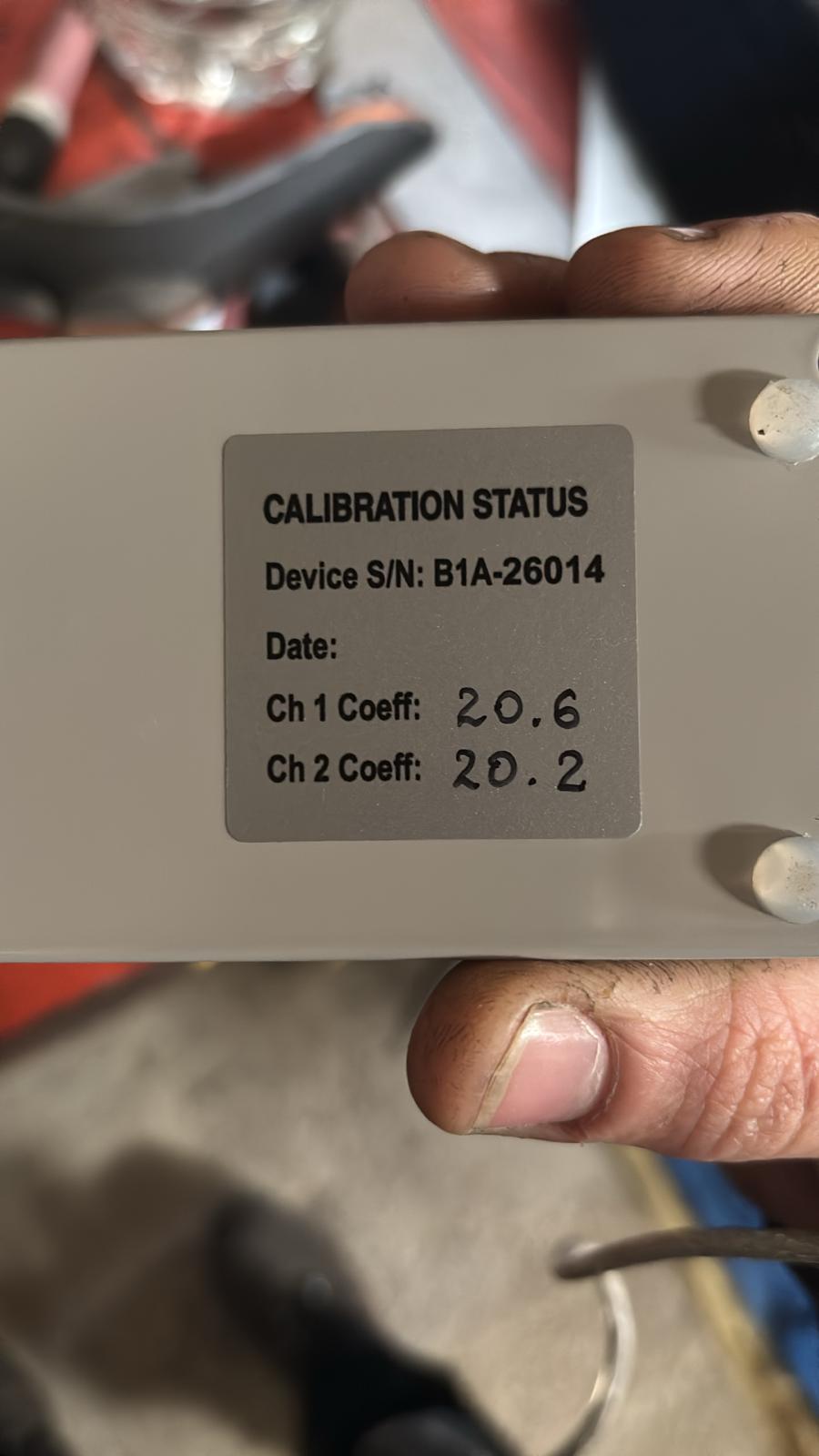
Kalibravimo koeficientai — nepameskite jų!
Kiekvienas komplektas turi savo kanalų jautrumo koeficientus (paprastai 12–25 ribose). Jie užrašomi:
- ant lipduko matavimo bloko apačioje,
- ant dėžutės,
- faile standartiniame USB raktelyje (
econfig/ebalan.cfg).
Jie įvedami programinėje įrangoje: F4 – Settings. Iš naujo įdiegus arba atnaujinus programinę įrangą koeficientai turi būti užsirašyti iš anksto ir įvesti iš naujo — kitaip prietaisas rodys neteisingas vibracijos reikšmes. Neišmeskite dėžutės, kol neperrašėte skaičių.
Prijungimas — greitas kontrolinis sąrašas
- 1 jutiklis (kanalas X1) — ant 1 plokštumos atramos; 2 jutiklis (X2) — ant 2 plokštumos atramos. Jutiklio ašis radialinė.
- Tachometras ant magnetinio stovo, spindulys nukreiptas į žymą, stovas neturi vibruoti.
- Priveržkite jungtis: atsilaisvinusi jungties veržlė sugauna 50 Hz gaudesį; blogas kontaktas priverčia jutiklį “rodyti nulį”.
- Prijunkite matavimo bloką prie nešiojamojo kompiuterio per USB. Paleiskite programinę įrangą, atverkite vibrometro režimą ir patikrinkite, ar teisingai rodomos apsukos, o amplitudė ir fazė yra stabilios.
Greitas jutiklio savitikrinimas
Jei įtariate jutiklį:
- vibrometro režimu švelniai pabaksnokite/pakratykite jutiklį — rodmuo turi reaguoti;
- padėkite abu jutiklius greta ant to paties paviršiaus: jų rodmenys turėtų būti panašūs;
- „nuliniai“ rodmenys (0,01) beveik visada reiškia nutrūkusį laidą ar atsilaisvinusį jungties kontaktą, o ne mirusį jutiklį.
Tachometro jungties X1 kontaktų išdėstymas (savarankiškam prijungimui)
| Kontaktas | Tikslas | Viela |
|---|---|---|
| 1 | GND | juoda |
| 2 | VCC (maitinimas) | raudona |
| 6 | Z-OUT (signalas) | ruda |
| 3, 4, 5, 7 | nenaudojamas | — |
Tikrasis lygis jungtyje yra ~3–5 V. Vietoje tachometro galima paduoti enkoderio indekso impulsą (1 impulsas per apsisukimą).

