← Balanset-1A Videnbase — alle kapitler
Pakkeindhold (Full Kit)
- Måleenhed (2 vibrationskanaler + tachometerkanal), USB-forsynet fra den bærbare
- 2 vibrationssensorer (accelerometre) på magneter, 5 m kabel (op til 10 m kan bestilles)
- Lasertachometer (optisk sensor) med magnetstander
- Elektronisk vægt (op til 500 g, 0,1 g trin)
- Reflekterende tape til mærket
- Software på en USB-stick
- Plastikkasse
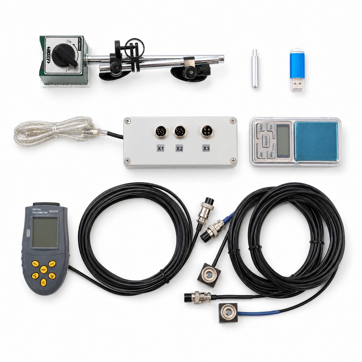
OEM versionen er den samme, men uden kuffert, magnetstander og vægt. En bærbar/tablet følger ikke med.
Til mulchere er prøve- og korrektionsvægte ofte 0.5–1 kg, så vægte op til 2 kg er praktiske.
Hovedspecifikationer
| Parameter | Værdi |
|---|---|
| Vibrationshastighed (RMS) | 0,02 – 80 mm/s |
| Frekvensområde | 5 – 1000 Hz |
| Omdrejninger i minuttet | 100 – 100,000 rpm |
| Fasenøjagtighed | ±1° |
| Afbalanceringsplaner | 1 eller 2 |
| Rotormasse | ikke begrænset af metoden (virkelig rekord — en 24.000 kg rotor) |
| PC | Windows 7/8/10/11, USB-port. Tablets — kun fuld Windows (Android/iOS virker ikke) |
Praktiske bemærkninger:
- praktisk balanceringsområde — omkring 300–60,000 rpm;
- grundlæggende lejefejlfrekvenser (BPFO/BPFI) kan ses i spektret;
- for meget lette rotorer (nogle få snese gram) opnås en opløsning ned til 0.02 mm/s ved at øge antallet af middelværdier.
Vibrationssensorer
- Type — accelerometre (baseret på ADXL335), der udsender vibrationshastighed. De kræver strøm fra enheden — deraf de skærmede kabler med tre ledere.
- Måleaksen forløber langs magneten (vinkelret på monteringsfladen). Montér sensoren, så dens akse peger radialt (på tværs af rotationsaksen), normalt vandret på lejehuset. Montering “på endefladen” (aksial retning) er en klassisk fejl, der forhindrer afbalanceringen i at konvergere.
- X1 → plan 1, X2 → plan 2. Byt ikke kanalerne om: byttede sensorer “vender” vinklerne.
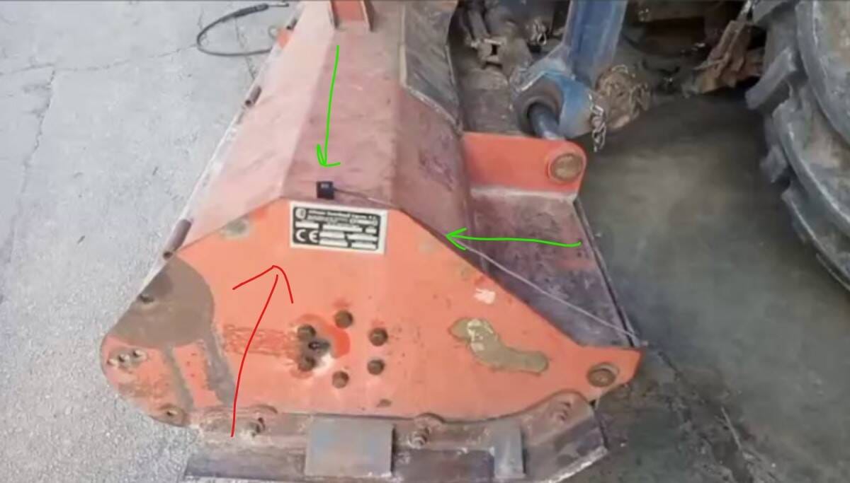
- Kablet er det svage punkt: en sensor, der trækkes ind i rotoren, får som regel kablet revet af. Før kablerne, så de ikke kan blive viklet ind.
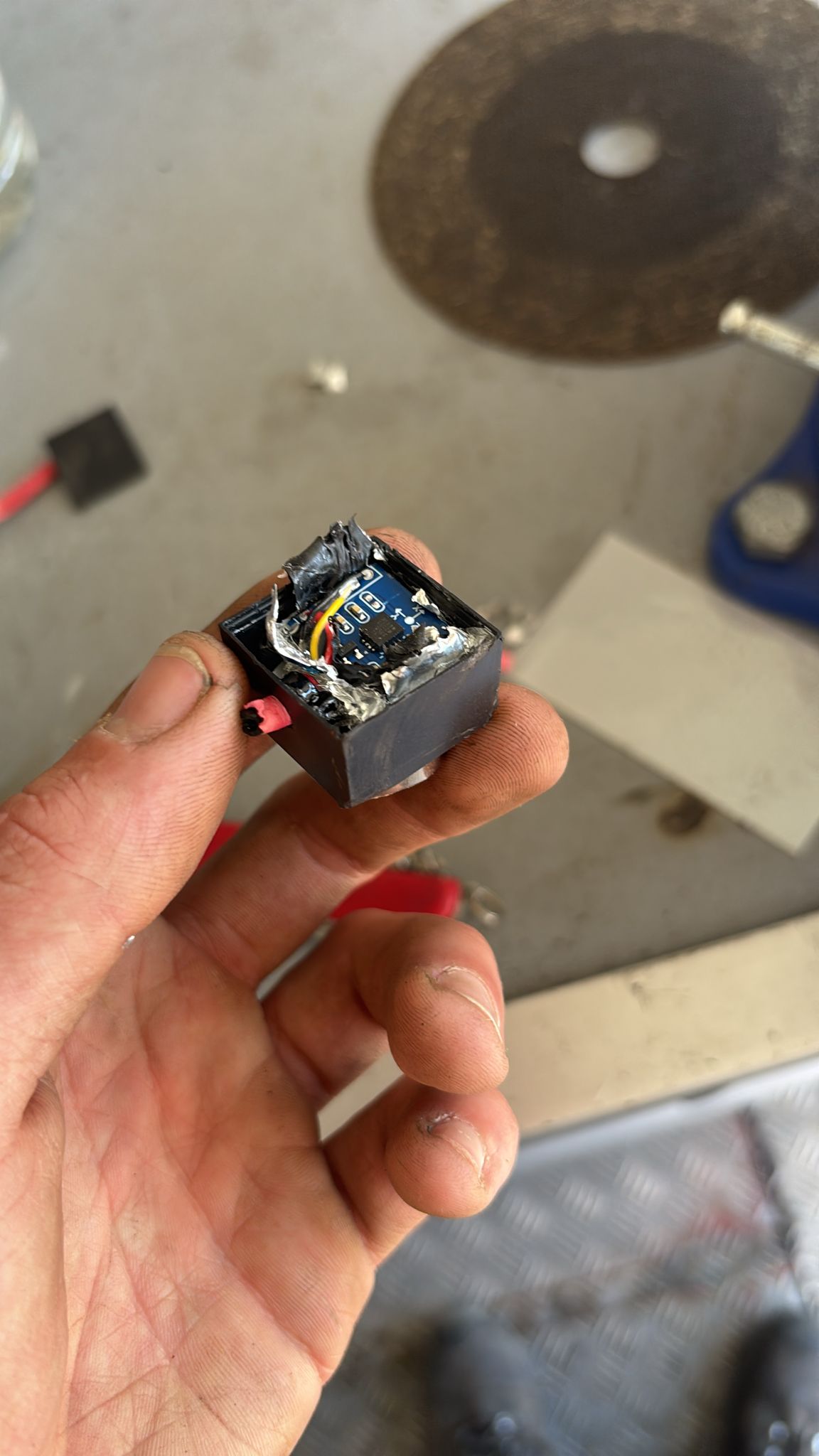
- Sensorernes levetid er 5–7 år eller mere; ingen årlig kalibrering nødvendig.
Laseromdrejningstæller
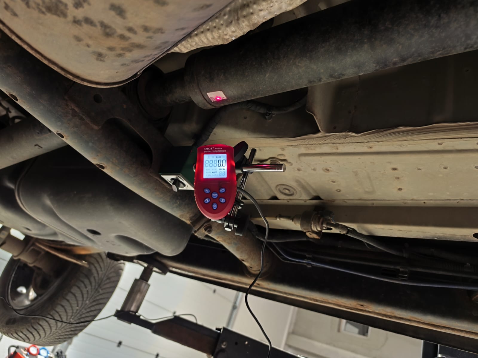
- Monteres på magnetstanderen og lyser på et Reflekterende mærke (et stykke tape fra sættet) sat på rotoren.
- Giver enheden omdrejningstallet og referenceimpulsen til fasen. Én impuls pr. omdrejning = ét mærke.
- Sæt mærket på nav/aksel, ikke på et blad: blanke blade, remskivehuller og svejsesømme forårsager falske udslag (detaljer i kapitel 08).
- Den mest skrøbelige del af sættet — beskyt den mod stød og mod at få kablet trukket ind i rotoren.
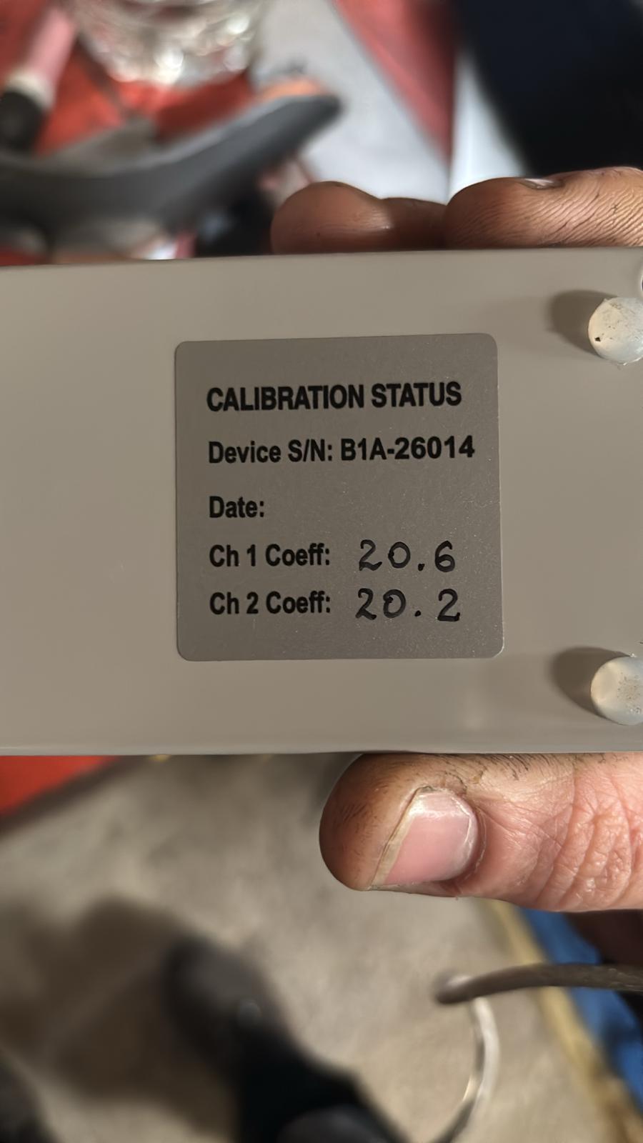
Kalibreringskoefficienter — mist dem ikke!
Hvert sæt har sine egne kanalfølsomhedskoefficienter (typisk værdier i intervallet 12–25). De er noteret:
- på mærkatet på bunden af måleenheden,
- på boksen,
- i en fil på den medfølgende USB-stick (
econfig/ebalan.cfg).
De indtastes i softwaren: F4 – Settings. Efter geninstallation eller opdatering af softwaren skal koefficienterne noteres på forhånd og indtastes igen — ellers vil enheden vise forkerte vibrationsværdier. Smid ikke æsken væk, før du har noteret tallene.
Tilslutning — en hurtig tjekliste
- Sensor 1 (kanal X1) — på plan-1-understøtningen; sensor 2 (X2) — på plan-2-understøtningen. Sensorakse radial.
- Tachometer på magnetstanderen, stråle på mærket, standeren må ikke vibrere.
- Stram stikforbindelserne: en løs stikmøtrik opfanger 50 Hz-brum; en dårlig kontakt får en sensor til at “vise nul”.
- Enhed til bærbar via USB. Start softwaren, åbn tilstanden Vibrometer og bekræft, at omdrejningstallet vises korrekt, og at amplitude og fase er stabile.
Hurtig selvtest af sensor
Hvis du mistænker en sensor:
- i vibrometertilstand skal du banke let på/ryste sensoren — aflæsningen skal reagere;
- sæt begge sensorer side om side på samme overflade — aflæsningerne bør være tæt på hinanden;
- “Nul”-aflæsninger (0,01) betyder næsten altid en brudt ledning eller en løs kontakt i stikket, ikke en defekt sensor.
Pinout for takometerstik X1 (til DIY-tilslutninger)
| Stift | Formål | Tråd |
|---|---|---|
| 1 | GND | sort |
| 2 | VCC (forsyning) | rød |
| 6 | Z-OUT (signal) | brun |
| 3, 4, 5, 7 | bruges ikke | — |
Det faktiske niveau ved stikket er ~3–5 V. I stedet for tachometeret kan du tilføre en encoders indeksimpuls (1 impuls pr. omdrejning).

